39
Impact of Battery Energy Storage Systems (BESS) on Distribution Networks Based on WGC6.30 Report Convener Nikos Hartziargyriou SC C6 30 November 2018

Impact of Battery Energy Storage Systems (BESS) on
Distribution Networks
Based on WGC6.30 Report
Convener Nikos Hartziargyriou
SC C6
30 November 2018

TABLE OF CONTENTS
SECTION 1 Battery energy storage systems – general considerations
SECTION 2 BESS impacts and benefits on the distribution grid
SECTION 3 BESS as a power source – features and operation
SECTION 4 Planning and design considerations
SECTION 5 Grid codes and standards
SECTION 6 International experiences – installations
SECTION 7 Best practices
SECTION 8 Closing remarks
Acknowledgement: this tutorial is based on the CIGRE Technical Brochure TB 721
“The Impact of Battery Energy Storage Systems on Distribution Networks” of Study Committee C6,
convenor Nikos Hatziargyriou, Greece

SECTION 1
TUTORIALBATTERY ENERGY STORAGE SYSTEMS (BESS)
GENERAL CONSIDERATIONS

BESS generic architecture and controls
Source: CIGRE WG C6-30 brochure

Basic model of the storage element
Source: EPRI

Energy storage – power and energy
Source: EPRI, December 2010Power, W
Operation
duration
(Time)
Energy = P * t

SECTION 2
TUTORIALBESS IMPACTS AND BENEFITS
ON ELECTRIC GRIDS

Energy storage systems – features
Source: CIGRE WG C6-30 brochure

GRID STABILISATION ENERGY STORAGE
ms hrs
Load Shifting/Leveling
Stabilization/Frequency
Peak Shaving
Smoothing/Capacity firming
Power qualityStandalone/Island mode
Time (Energy)
Po
wer
Spinning Reserve
Source: ABB
Energy storage – grid benefits

BESS – balancing renewable resources
Time, hr
Power, kW
PV Power
Diesel Power Battery Power
Source: CIGRE WG C6-30 brochure

BESS – frequency regulation
Frequency
Hz
Battery
current
Source: CIGRE WG C6-30 brochure

Load shifting – feeder load reduction
Power
Time, hrSource: CIGRE WG C6-30 brochure

SECTION 3
TUTORIALBESS AS A POWER SOURCE
FEATURES AND OPERATION

BESS integration – role in microgrid
Grid Substation
Transformer
Breaker
Dispatchable Generation
Sensitive and critical loads
CHP
Battery storage
Controllable loads
Load
Microgrid controlsystem
Non-dispatchable generation
Load
Solar Wind
Microgrid
Centralized electrical storage
Storage
Load

BESS impact on congestionLocal Balancing
Source: CIGRE WG C6-30 brochure

DER configuration and grid interface
P
ac-dc
Transformer
(reactor)
MV
Grid
(LV)
Q
Independent
P and Q control
(VSC)
P
PV
system
Wind
turbine
generator
system
Battery/
flywheel
energy
storage
system
P
P
INVERTER
Inverters
▪ Have grid supportive capabilities –Q injection, P injection
▪ Control capability – P and Q outputs can be independently controlled
▪ Can be equipped with supplementary control functions/loops, to help support the grid including
▪ Peak power P limitation/curtailment at the point of connection
▪ Reactive power Q regulation as a function of bus voltage
▪ P regulation as a function of bus voltage
▪ P regulation as a function of system frequency
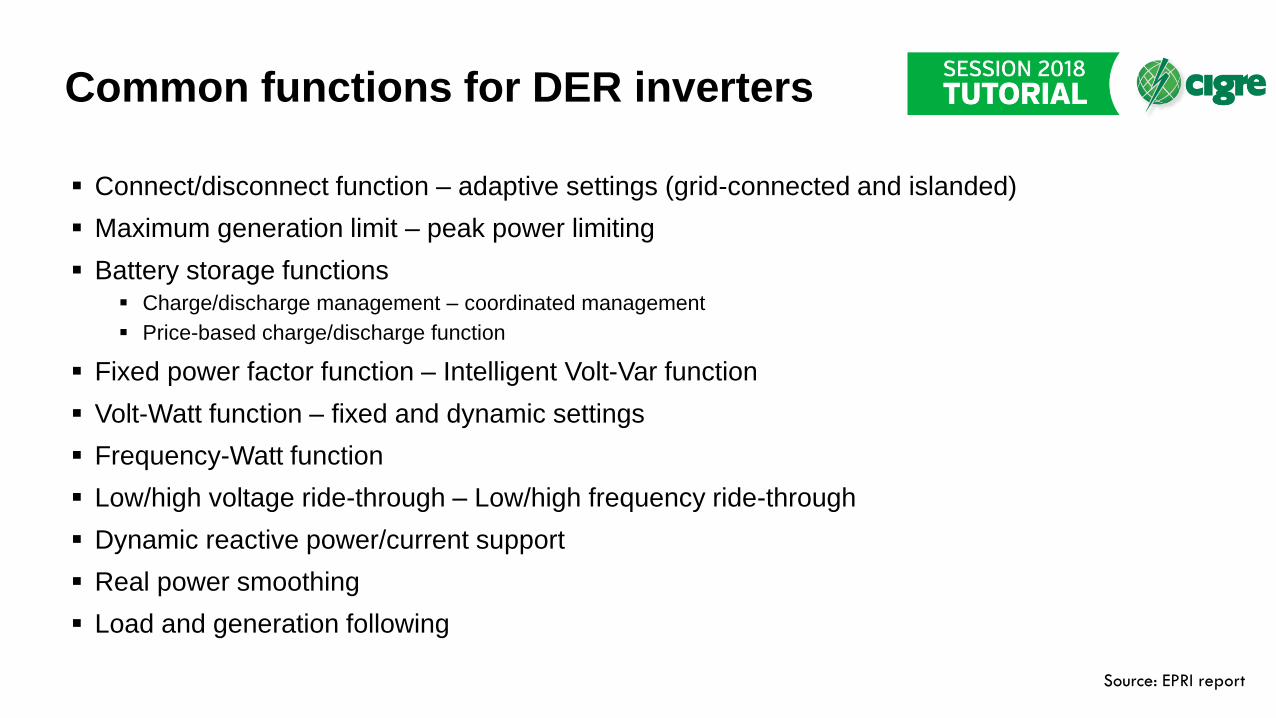
Common functions for DER inverters
▪ Connect/disconnect function – adaptive settings (grid-connected and islanded)
▪ Maximum generation limit – peak power limiting
▪ Battery storage functions▪ Charge/discharge management – coordinated management
▪ Price-based charge/discharge function
▪ Fixed power factor function – Intelligent Volt-Var function
▪ Volt-Watt function – fixed and dynamic settings
▪ Frequency-Watt function
▪ Low/high voltage ride-through – Low/high frequency ride-through
▪ Dynamic reactive power/current support
▪ Real power smoothing
▪ Load and generation following
Source: EPRI report

DER inverter – intelligent function
Volt-Var function – settingsSource: EPRI report

BESS interface and structure – functions
P
ac-dc dc-dc Battery
Transformer
(reactor)
MV
Grid
(LV)
P
Q
Independent
P and Q control
(VSC)
INVERTER▪ The BESS uses the same basic
ac side structure as other power electronic interfaced DER
▪ Supplementary DER control functions can be implemented
▪ Differences with DER generators
▪ The ability to act as both load and generator, depending on the real power P reference and the state of charge
▪ It can act as a reference bus in islanded operation, setting frequency f and bus voltage V
▪ It can be used to smooth out power variations produced by the operation of renewable energy resources based generators and loads

BESS operating regions and modes
IqInductive Var
IqCapacitive Var
IdCharging W
IdDischarging W
Nominal SConstant VA
Short term
operation
Nominal
charging I
Maximum
discharging I
Nominal
inverter
rating
Maximum
inverter
rating
▪ Inverter interfaced BESS operating modes – 4-Q
▪ Real power (P) injection or absorption
▪ Reactive power (Q), leading or lagging
▪ Combination of P and Q
▪ Basic relations
▪ P = V x Id▪ Q = V x Iq▪ S = V x I
▪ Operating constraints – kVA vs KWh
▪ Inverter rated in current (kVA rating)
▪ BESS real power capability = energy stored (kWh)
▪ Limitations: charge/discharge rate

BESS – a virtual synchronous generator
Source: CIGRE WG C6-30 brochure

SECTION 5
TUTORIALGRID CODES AND STANDARDS

BESS grid codes and standards
▪ DER standards and grid codes applicable to BESS
▪ Ability of the DER to regulate the voltage at the bus to which it is connected
▪ Provision for reactive power in support of the grid voltage
▪ Possibility of real power curtailment – non-receptive grid
▪ Low/high voltage ride-through requirement
▪ Low/high frequency ride-through requirement
▪ Power system stabilization functions – damping power system oscillations
▪ Reference grid codes and standards: IEEE Std 1547, CEI 021, ENTSO-E,CENELEC, utility grid codes

Grid codes – V and f requirements
0.1Time, s
10
1.2
1.0
1.4
1
Voltage, pu
0.5
0
Trip
Trip
Ride-through
0.1Time, s
100
1.0
1.1
1
Frequency, pu
0.9 Trip
Trip
Ride-through
Source: Adapted from IEEE Std 1547
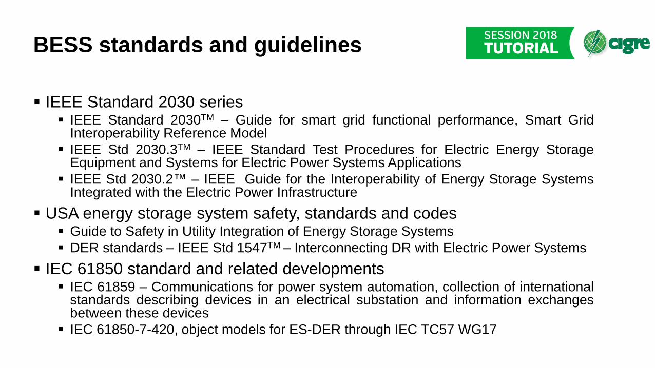
BESS standards and guidelines
▪ IEEE Standard 2030 series▪ IEEE Standard 2030TM – Guide for smart grid functional performance, Smart Grid
Interoperability Reference Model
▪ IEEE Std 2030.3TM – IEEE Standard Test Procedures for Electric Energy StorageEquipment and Systems for Electric Power Systems Applications
▪ IEEE Std 2030.2™ – IEEE Guide for the Interoperability of Energy Storage SystemsIntegrated with the Electric Power Infrastructure
▪ USA energy storage system safety, standards and codes▪ Guide to Safety in Utility Integration of Energy Storage Systems
▪ DER standards – IEEE Std 1547TM – Interconnecting DR with Electric Power Systems
▪ IEC 61850 standard and related developments▪ IEC 61859 – Communications for power system automation, collection of international
standards describing devices in an electrical substation and information exchangesbetween these devices
▪ IEC 61850-7-420, object models for ES-DER through IEC TC57 WG17

BESS integration considerations
▪ Grid integration and interconnection requirements▪ Utility interconnection agreement
▪ Interfacing with the Distribution Management System (DMS) – DSO control
▪ Connection to primary/secondary substations or distribution feeders
▪ Connection to grid nodes and customers (building load management)
▪ Grid integration studies▪ System studies – impact on the grid, harmonics and power quality
▪ Protection studies – short circuit contributions (inverter limited)
▪ Combining different energy storage technologies – alternative designs▪ Purpose: cover a wider range of operating conditions (dynamic and steady state) and
energy requirements, as needed
▪ Example: combining a flywheel energy storage system (ESS), short term power, with abattery ESS, medium term power

SECTION 6
TUTORIALINTERNATIONAL EXPERIENCES
INSTALLATIONS

BESS Installations
Source: CIGRE WG C6-30 brochure
Analysis of DOE Global Energy Storage Databasewith 1,575 storage projects registered (171GW of operational capacity) by July 2016
Battery installations above 6MW, at renewable and
conventional power plants/stations and off-grid
installations excluded.
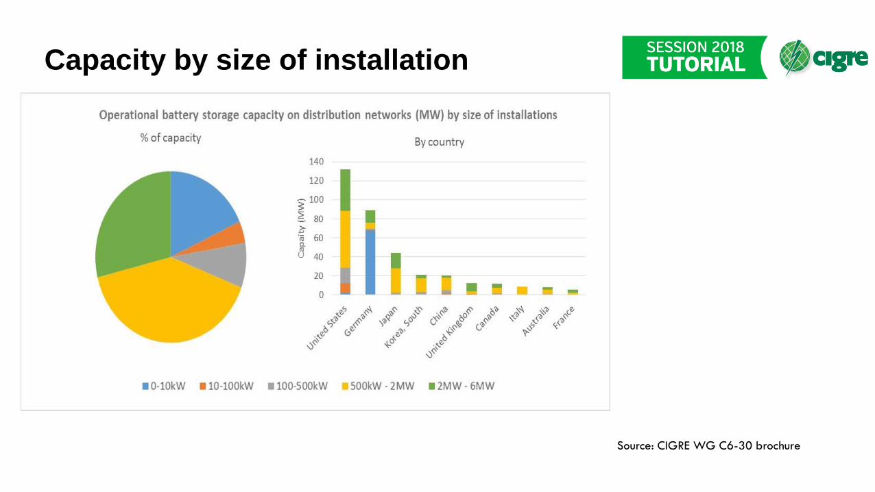
Capacity by size of installation
Source: CIGRE WG C6-30 brochure

BESS Technologies
Source: CIGRE WG C6-30 brochure
Lithium-ion batteries (~70%)

Demonstration projects – use cases
Source: CIGRE WG C6-30 brochure
Analysis of DOE Global Energy Storage Databasewith 1,575 storage projects registered (171GW of operational capacity) by July 2016
Energy arbitrage: ‘Electric Bill Management’,‘Electric Bill Management with Renewables’, ‘ElectricEnergy Time Shift’.Ancillary services: ‘Frequency Regulation’, ‘LoadFollowing (Tertiary Balancing)’, ’Electric SupplyReserve Capacity – Spinning’, ‘Electric SupplyReserve Capacity – Non-spinning’, ‘Voltage Support’,‘Black start’, ’Ramping’, ’Transmission support’Balancing renewable energy: ‘RenewablesCapacity Firming’, ‘Renewables Energy Time Shift’,‘Onsite Renewable Generation Shifting’Load levelling and peak demand: ‘Demandresponse, ‘Distribution upgrade due to solar’,‘Distribution upgrade due to wind’, ‘Transmissionupgrades due to solar’, ‘Transmission upgrades due towind’, ‘Transportable Transmission / DistributionUpgrade Deferral’, ‘Stationary Transmission /Distribution Upgrade Deferral’, ‘TransmissionCongestion Relief’, ‘Electric Supply Capacity’, ‘On-SitePower’Resiliency: ‘Resiliency’, ‘Grid-Connected Commercial(Reliability & Quality)’, ‘Grid-Connected Residential(Reliability)’, ‘Microgrid capability’

Demonstration projects – use cases
Source: CIGRE WG C6-30 brochure
Analysis of DOE Global Energy Storage Databasewith 1,575 storage projects registered (171GW of operational capacity) by July 2016 Primary use-cases depending on size of installation

Demonstration projects – ownership
Source: CIGRE WG C6-30 brochure
35% of project entries have only one high-level use case category, equivalent to 49% of the installed capacity.

Demonstration projects – Japan
▪ Purpose: demonstration of Battery SCADA
▪ Location: Substation and customer side
▪ Battery: Li-Ion (300 kW, 100 kWh), Li-Ion (100 kW,100 kWh), Li-Ion (250kW,250 kWh) at Substation; Li-Ion (45 kWh), Li-Ion (8.4 kWh) x 3 oncustomer side
▪ Applications:▪ Short period change adjustment
▪ Long period adjustment of the day interval
▪ Spinning reserve
▪ Demand response (without load control) – customer side
▪ Commissioning: 2010 - 2014
▪ Learning experiences▪ BESS can replace conventional generators in cases of severe supply and demand
imbalance, provide peak load shiftingSource: CIGRE WG C6-30 brochure

Demonstration projects – UK
▪ Purpose: demonstration and trial of BESS
▪ Location: distribution grid/feeder
▪ Battery: Li-Ion (6 MW, 10 MWh)
▪ Applications:▪ Peak Shaving – maintain demand within security-of-supply limits
▪ Reactive Power (Voltage) Support
▪ Dynamic frequency response and static frequency response
▪ Reserve – short term operating reserve
▪ Long term market optimization – flexible commercial arrangements, business models
▪ Commissioning: December 2014
▪ Learning experiences: quantification of value streams; investment deferral;system loss reduction; support for the integration of renewable resources;increased operational flexibility
Source: CIGRE WG C6-30 brochure

Demonstration projects – Italy
▪ Purpose: demonstration of the benefits of BESS
▪ Location: Industrial district, with generation mix: wind, PV, combined heatand power (CHP), MV grid, in parallel with a large PV plant (1 MW)
▪ Battery: Li-Ion (1 MW, 200 kWh)
▪ Applications:▪ Primary frequency regulation
▪ Allowing PV generation to follow contracted daily profiles, compensating deviations
▪ Buying and selling energy according to market price
▪ Commissioning: 2013
▪ Learning experiences: demonstrating possibility of combining various gridservices in one single storage system, integrating the output of a PVsystem; economical feasibility of storage system projects
Source: CIGRE WG C6-30 brochure

SECTION 8
TUTORIALCLOSING REMARKS

BESS deployment – practical issues
▪ Electric energy storage – justifications
▪ Balancing variable generation from renewable energy resources – if no alternative
▪ Ancillary services provision – if market exists for such products
▪ Participation in electricity markets: leveraging prices, time of use pricing – if option exists
▪ Considerations in justifying the deployment of energy storage
▪ Alternative approaches – demand response/management, curtailing renewable generation
▪ Cost of operation, economics – steady state losses, store/retrieve efficiency, maintenance
▪ Life cycle (considering utility infrastructure), replacement, battery disposal, repurposing
▪ Dynamic performance – limitations
▪ Other issues
▪ Ownership and operation
▪ Reliability, availability, maintainability

Copyright © 2018
This tutorial has been prepared based upon
the work of CIGRE and its Working Groups.
If it is used in total or in part, proper
reference and credit should be given to
CIGRE.
Disclaimer notice
“CIGRE gives no warranty or assurance
about the contents of this publication, nor
does it accept any responsibility, as to the
accuracy or exhaustiveness of the
information. All implied warranties and
conditions are excluded to the maximum
extent permitted by law”.
Copyright &
Disclaimer notice


