15th Australasian Fluid Mechanics Conference The University of Sydney, Sydney, Australia 13-17 December 2004 Impact of Outlet Boundary Conditions on the Flow Properties within a Cyclone St. Schmidt, H. M. Blackburn and M. Rudman CSIRO Manufacturing & Infrastructure Technology PO Box 56, Highett, Victoria, 3190 AUSTRALIA Abstract In this study the influence of the exit tube geometry on the over- all flow properties of cyclones is investigated using detached eddy simulation. The results for different exit pipe shapes and lengths reveal that under certain conditions the outlet has an up- stream effect on the flow behaviour within the cyclone. This can in turn result in poor build-up of swirl in the crucial region of the cyclone and substantially reduce the efficiency of the cy- clone as a particle-separation device. Introduction Cyclones are widely used in the industrial cleaning process, where particles are removed from particle-laden carrier flows without the need for using particle filters. The performance of these maintenance-free devices depends to a large extent on the swirl velocity within the cyclone as this quantity directly deter- mines the centrifugal force imposed on the particles and at the same time limits the ability to separate particles from the flow. In cyclone design it is therefore vital to accurately calculate the flow in order to be able to predict the overall performance of the cyclone. The work here deals only with single-phase flow of carrier fluid, as this must be correctly predicted before the solids phase can be considered. Owing to the technological relevance of cyclones, flow simula- tions have been carried out in the last decades, as appropriate computational techniques have been developed [1, 2]. Since the Reynolds numbers for cyclone flows are usually in the order of Re = 10 6 and the flow itself is inherently very complex due to strong streamline curvature and anisotropic turbulent struc- tures, these flows require sophisticated turbulence modelling in order to obtain reliable and trustworthy results. Of the avail- able models to be applied to the Reynolds-averaged Navier– Stokes (RANS) equations, full Reynolds-stress transport mod- els (RSTM) are best able to cope with turbulence anisotropy and satisfactorily predict these flows [1]. Wall-resolving large eddy simulation (LES), which directly re- solves the main turbulent flow structures down to the wall, while potentially the most accurate approach, remains extremely ex- pensive in terms of computational effort and is therefore not useful in product design. However, combinations of RANS and LES, such as detached eddy simulation (DES, [7]) provide at- tractive alternatives, since this numerical method combines the advantages of LES and RANS. Like LES, DES is capable of re- solving unsteady flow features but utilises wall models similar to RANS in order to reduce the spatial resolution in the crucial near-wall region. Previous results based on LES and DES revealed differences in the flow predictions depending on the inflow conditions, and exhibited deficiency in predicting the swirl level in the cyclonic part of the cyclone [3]. Perhaps more importantly, the results in the present study show that in order to successfully predict flow within the cyclone, care must be paid to the treatment given to the exit tube, downstream of the vortex finder, and external to the cyclone body. It will be demonstrated that the swirl velocity within the cyclone can be influenced dramatically by changing the length and shape of the vortex finder. Highly swirling flows can promote propagation of flow information upstream, against the mean flow direction, by pressure waves, similar to pressure waves in compressible flows [10]. Our results further suggest that the performance of the cyclone in an industrial environment will be greatly influenced by the actual inflow and outflow conditions. Hence, cyclone design should not be restricted to the cyclone itself, but also encompass the surrounding ductwork. Detached Eddy Simulation This numerical technique based on the solution of the three- dimensional unsteady Navier–Stokes equations was first intro- duced by Spalart et al. [7] for the simulation of flows past air- foils at high angles of attack, which feature massive flow separa- tion and the shedding of large vortical structures into the wake. In terms of numerical modelling, this approach combines meth- ods solving the Reynolds-averaged Navier–Stokes (RANS) equations with large-eddy simulation (LES). Owing to the fact that (like LES) DES resolves the turbulence spectrum up to a certain cut-off wavenumber, it is capable of capturing helical vortices which form around the centreline of a cyclone, a fea- ture common to many swirling flows. At the same time, by avoiding the necessity for fine (eddy-resolving) mesh structure near the walls, DES is substantially cheaper than LES. From a turbulence modelling point of view, DES is obtained by a slight modification of the destruction term in the Spalart– Allmaras one-equation RANS model [6], resulting in a lim- itation of the length scale by the grid spacing. This hybrid approach employs the unmodified RANS model in wall areas while turning itself into a one-equation subgrid-scale model in regions located off the wall. The model has been implemented and validated for internal and external high Reynolds number flows [4, 5]. Numerical Method The Navier–Stokes equations are discretised using a cell- centered finite-volume method based on block-structured grids [11]. All diffusive fluxes are approximated with a central- differencing scheme (CDS). For the convective fluxes, the use of blending functions ensures that in the RANS region a third- order upwind-biased QUICK scheme is used, while in the LES region, CDS is recovered [8]. The time integration is of sec- ond order, using a fully implicit three-level scheme, ensuring CFL stability even in coarse regions of the mesh where the CDS would produce unphysical solutions owing to high Peclet numbers. The flow solver is parallelised using a blockwise do- main decomposition technique employing message passing li- brary MPI for inter-block communication. Computations were carried out using 28–34 nodes on the APAC Alpha cluster with the same set of boundary conditions, timestep and total integra-
Transcript
15th Australasian Fluid Mechanics ConferenceThe University of Sydney, Sydney, Australia13-17 December 2004
Impact of Outlet Boundary Conditions on theFlow Properties within a Cyclone
In this study the influence of the exit tube geometry on the over-all flow properties of cyclones is investigated using detachededdy simulation. The results for different exit pipe shapesandlengths reveal that under certain conditions the outlet hasan up-stream effect on the flow behaviour within the cyclone. Thiscan in turn result in poor build-up of swirl in the crucial regionof the cyclone and substantially reduce the efficiency of thecy-clone as a particle-separation device.
Introduction
Cyclones are widely used in the industrial cleaning process,where particles are removed from particle-laden carrier flowswithout the need for using particle filters. The performanceofthese maintenance-free devices depends to a large extent ontheswirl velocity within the cyclone as this quantity directlydeter-mines the centrifugal force imposed on the particles and at thesame time limits the ability to separate particles from the flow.In cyclone design it is therefore vital to accurately calculate theflow in order to be able to predict the overall performance ofthe cyclone. The work here deals only with single-phase flowof carrier fluid, as this must be correctly predicted before thesolids phase can be considered.
Owing to the technological relevance of cyclones, flow simula-tions have been carried out in the last decades, as appropriatecomputational techniques have been developed [1, 2]. SincetheReynolds numbers for cyclone flows are usually in the orderof Re=106 and the flow itself is inherently very complex dueto strong streamline curvature and anisotropic turbulent struc-tures, these flows require sophisticated turbulence modelling inorder to obtain reliable and trustworthy results. Of the avail-able models to be applied to the Reynolds-averaged Navier–Stokes (RANS) equations, full Reynolds-stress transport mod-els (RSTM) are best able to cope with turbulence anisotropy andsatisfactorily predict these flows [1].
Wall-resolving large eddy simulation (LES), which directly re-solves the main turbulent flow structures down to the wall, whilepotentially the most accurate approach, remains extremelyex-pensive in terms of computational effort and is therefore notuseful in product design. However, combinations of RANS andLES, such as detached eddy simulation (DES, [7]) provide at-tractive alternatives, since this numerical method combines theadvantages of LES and RANS. Like LES, DES is capable of re-solving unsteady flow features but utilises wall models similarto RANS in order to reduce the spatial resolution in the crucialnear-wall region.
Previous results based on LES and DES revealed differencesin the flow predictions depending on the inflow conditions, andexhibited deficiency in predicting the swirl level in the cyclonicpart of the cyclone [3]. Perhaps more importantly, the results inthe present study show that in order to successfully predictflowwithin the cyclone, care must be paid to the treatment given tothe exit tube, downstream of the vortex finder, and external to
the cyclone body. It will be demonstrated that the swirl velocitywithin the cyclone can be influenced dramatically by changingthe length and shape of the vortex finder. Highly swirling flowscan promote propagation of flow information upstream, againstthe mean flow direction, by pressure waves, similar to pressurewaves in compressible flows [10].
Our results further suggest that the performance of the cyclonein an industrial environment will be greatly influenced by theactual inflow and outflow conditions. Hence, cyclone designshould not be restricted to the cyclone itself, but also encompassthe surrounding ductwork.
Detached Eddy Simulation
This numerical technique based on the solution of the three-dimensional unsteady Navier–Stokes equations was first intro-duced by Spalart et al. [7] for the simulation of flows past air-foils at high angles of attack, which feature massive flow separa-tion and the shedding of large vortical structures into the wake.
In terms of numerical modelling, this approach combines meth-ods solving the Reynolds-averaged Navier–Stokes (RANS)equations with large-eddy simulation (LES). Owing to the factthat (like LES) DES resolves the turbulence spectrum up to acertain cut-off wavenumber, it is capable of capturing helicalvortices which form around the centreline of a cyclone, a fea-ture common to many swirling flows. At the same time, byavoiding the necessity for fine (eddy-resolving) mesh structurenear the walls, DES is substantially cheaper than LES.
From a turbulence modelling point of view, DES is obtainedby a slight modification of the destruction term in the Spalart–Allmaras one-equation RANS model [6], resulting in a lim-itation of the length scale by the grid spacing. This hybridapproach employs the unmodified RANS model in wall areaswhile turning itself into a one-equation subgrid-scale model inregions located off the wall. The model has been implementedand validated for internal and external high Reynolds numberflows [4, 5].
Numerical Method
The Navier–Stokes equations are discretised using a cell-centered finite-volume method based on block-structuredgrids [11]. All diffusive fluxes are approximated with a central-differencing scheme (CDS). For the convective fluxes, the useof blending functions ensures that in the RANS region a third-order upwind-biased QUICK scheme is used, while in the LESregion, CDS is recovered [8]. The time integration is of sec-ond order, using a fully implicit three-level scheme, ensuringCFL stability even in coarse regions of the mesh where theCDS would produce unphysical solutions owing to high Pecletnumbers. The flow solver is parallelised using a blockwise do-main decomposition technique employing message passing li-brary MPI for inter-block communication. Computations werecarried out using 28–34 nodes on the APAC Alpha cluster withthe same set of boundary conditions, timestep and total integra-
tion time for each configuration, allowing valid comparisons tobe made.
Flow Configuration
The cyclone (figure 1a) features an outer diameterD = 2R anda half-angle ofα=20◦ in the conical region and an underflow-exit pipe at the bottom end for the collection of particles. Inthis study this outflow is closed for all simulations as only thecarrier flow is investigated. Hence only the outflow through thevortex finder with a diameterd at the top of the cyclone is usedand convective outflow boundary conditions are imposed on thisoutlet plane.
All velocities presented here are normalised by the bulk veloc-ity in the inlet duct. The kinematic viscosity of the fluid wasset so that the Reynolds number based on this velocity and thecyclone body diameterD wasRe= 1×10⁶, matching the cor-responding experiments [9]. Dimensions are normalised byR,and the reference axial location,z0, is placed in line with thebottom of the cylindrical cyclone outer body. The vortex finderterminates atz∗/R= (z−z0)/R≈ 0.5.
r / R
z/R
-1 0 1
0
1
2
3
4
5
6
z0/R
Outflow
Inflow
(a) (b)
Figure 1: Cyclone geometry and block-structured grid.
Exit Tube Geometries
The results of previous cyclone LES [3] using a spectral-element method on a domain comparable to the one shown infigure 2a, showed a strong under prediction of the swirl veloc-ity component in the cyclone. DES results confirmed that thechoice of a short exit tube length (cf. figure 2a) has an adverseeffect on the swirl velocity within main part of the cyclone andcontributed to the lack of agreement with the experiments [9].
The main goal of this paper is therefore to examine the effectsof different outflow geometries on the swirl velocity in the cy-clone. The work concentrated on both the extension of theaxisymmetric exit tube as well as different outlet geometries,namely a short, medium and long straight exit (figures 2a-c),anoutlet with centre-body blocking the core of the flow at the exit(figure 2d), a radial outlet ring surrounding the exit area (fig-
SHORT MEDIUM LONG LONG-CENTRE
LONG-RADIAL SHORT-BEND LONG-BEND
(a) (b) (c) (d)
(e) (f) (g)
Figure 2: Cyclone outlet geometries: short (a), medium (b) andlong (c) straight outlet; long with blocked centre part (d);longwith radial outlet (e); short with bend (f) and long outlet withbend similar to the experimental setup (g); arrows indicateout-flow direction.
ure 2e) as well as a short/long straight pipe with an additionalbend and extension tube (figures 2f/g). The original experimen-tal setup included an elongated rectangular inlet duct and aout-let geometry similar to the one depicted in figure 2g.
Results
The figures 3a-c show the distribution of the time-averagedswirl velocities at three locations within the cyclone for all ge-ometries including the previously mentioned simulation basedon theSHORT geometry (cf. fig. 2a). Obviously the simulationsbased on geometries with a longer exit are in much closer agree-ment with the measurements, except the geometry with the longvortex finder and the blocked centre (cf. figure 2d), which givesswirl velocity profiles comparable to those for theSHORT ge-ometry. In part, this setup was chosen because in the previousspectral element LES an axisymmetric centre body was placedin the outlet area in order to prevent any flow re-entering thedomain and de-stabilising the numerical scheme. The DES ofthis configuration suggests that this body slows down the swirlvelocity in the cyclone and contributes to the poor quality ofthe results. Comparing the results of the other geometries,itbecomes clear that beyond a certain exit tube length, the shapeof the geometry does not have a strong impact on the swirl inthe cyclone. Even the inclusion of the bend does not affect thesolution significantly.
The mean axial velocities are shown in figures 4a-c. Belowthe entry plane of the vortex finder (figure 4a) the results aremainly influenced by the length of the exit tube as the solutionstend to approach the results with bend included in the outletgeometry. The shorter the outlet, the more the velocity peakdrops and evens out the steep velocity gradients. In the con-ical part of the cyclone (figure 4b, c) the differences become
larger and two areas can be identified: a near-axis region, whichgives good overall agreement of all solutions, and an internalpart, located between the axis and the surrounding walls. Inthelatter region, the axial velocities of all solutions miss the ex-periments and tend to flow counter to the experimental results.The computations exhibit three radial locations where the veloc-ity changes direction, whereas the experiments do not suggestsuch behaviour. As only the solutions where swirl velocities areunder-predicted exhibit this behaviour, the results indicate thatdepending on the swirl more than one flow pattern may exist inthe cyclone body.
At the lower end (figure 4c), these differences become moreobvious and the geometries with longer exit tubes tend to agreemore with the experimental data than the low-swirl solutions.
Influence of Exit Tube Geometry
The differences in the results of the shorter cyclone geometries(SHORT/MEDIUM) compared to the other cases can be traced tofigure 5, where tangential velocity is represented by grey tonesranging fromW = 0 (black) toW = Wmax (white). The locationof the vortex core can be clearly identified as the dark regionmeandering around the centre line of the cyclone. It can be seenthat especially for the shorter geometries (figures 5a/b) the corebecomes increasingly perturbed and non-axial.
In part, this behaviour can be linked to flow at the entry to thevortex finder where, for the shorter geometries, the vortex coreis inclined to the exit plane, thereby promoting localised reverseaxial flow. As the solution evolves in time these instabilitieseventually wash away for the longer domains (figures 5c/d) butprevail in the shorter domains and prevent the flow from settlinginto a stable flow pattern. This state can be classified in terms offlow criticality as a high swirl-number case, as discussed in[10].According to their findings, swirling flows can have either a lowor a high swirl number called either supercritical or subcriti-cal respectively. Insupercritical flows no information from adownstream point can be transported upstream, whereas insub-critical flows a downstream disturbance can propagate upstreamhence changing the flow patterns there.
Figure 5: Location of the centre vortex for different exit tube ge-ometries visualised by time-averaged swirl velocity: short (a),medium (b) and long (c) straight outlet; long with blocked cen-tre part (d)
Figure 6 displays the axial velocity profiles in the vortex finderstarting just downstream of the entry plane atz∗/R≈ 0.5. Thevelocity evens out the asymmetry linked to the swirl velocityand begins a recovery towards a rotating pipe flow. At the mostdownstream location (figure 6c) massive reverse flow occurs inthe central part, resulting from by the strong vortex and thelowpressure associated with it. As even the geometries with thelongest exit tube have reverse flow at these locations, this re-verse flow in itself cannot be the main reason for the lack ofswirl observed in the short geometries. As only the blockageintheLONG-CENTRE geometry prevents this backflow, it seems tobe entirely driven by low pressure in the vortex core.
U
0 0.025 0.05 0.075 0.1
0
0.5
1
1.5
U
0 0.025 0.05 0.075 0.1
0
0.5
1
U
0 0.025 0.05 0.075 0.1
0
0.5
1
(c)
(b)
(a)
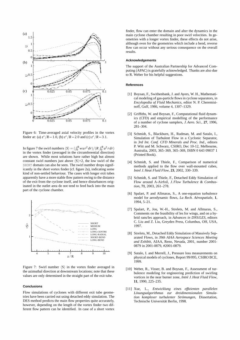
Figure 6: Time-averaged axial velocity profiles in the vortexfinder at: (a)z∗/R=1.0, (b)z∗/R=2.0 and (c)z∗/R=3.1.
In figure 7 the swirl numbers〈S〉= (R R0 wur2 dr)/(R
R R0 u2 rdr)
in the vortex finder (averaged in the circumferential direction)are shown. While most solutions have rather high but almostconstant swirl numbers just above〈S〉=2, the low swirl of theSHORT domain can also be seen. The swirl number drops signif-icantly in the short vortex finder (cf. figure 2a), indicatingsomekind of non-settled behaviour. The cases with longer exit tubesapparently have a more stable flow pattern owing to the distanceof the exit from the cyclone itself, and hence disturbances orig-inated in the outlet area do not tend to feed back into the mainpart of the cyclone chamber.
Figure 7: Swirl number〈S〉 in the vortex finder averaged inthe azimuthal direction at downstream locations; note thatthesevalues are only determined in the straight part of the exit tube.
Conclusions
Flow simulations of cyclones with different exit tube geome-tries have been carried out using detached eddy simulation.TheDES method predicts the main flow properties quite accurately,however, depending on the length of the vortex finder two dif-ferent flow pattern can be identified. In case of a short vortex
finder, flow can enter the domain and alter the dynamics in themain cyclone chamber resulting in poor swirl velocities. Inge-ometries with a longer vortex finder, these effects do not arise,although even for the geometries which include a bend, reverseflow can occur without any serious consequence on the overallresults.
Acknowledgements
The support of the Australian Partnership for Advanced Com-puting (APAC) is gratefully acknowledged. Thanks are also dueto R. Weber for his helpful suggestions.
References
[1] Boysan, F., Swithenbank, J. and Ayers, W. H., Mathemati-cal modeling of gas-particle flows in cyclone separators, inEncylopedia of Fluid Mechanics, editor N. P. Cheremisi-noff, Gulf, 1986, volume 4, 1307–1329.
[2] Griffiths, W. and Boysan, F., Computational fluid dynam-ics (CFD) and empirical modelling of the performanceof a number of cyclone samplers,J. Aero. Sci., 27, 1996,281–304.
[3] Schmidt, S., Blackburn, H., Rudman, M. and Sutalo, I.,Simulation of Turbulent Flow in a Cyclonic Separator,in 3rd Int. Conf. CFD Minerals and Proc. Ind., editorsP. Witt and M. Schwarz, CSIRO, Dec 10-12, Melbourne,Australia, 2003, 365–369, 365–369, ISBN 0 643 09037 1(Printed Book).
[4] Schmidt, S. and Thiele, F., Comparison of numericalmethods applied to the flow over wall-mounted cubes,Intnl J. Heat Fluid Flow, 23, 2002, 330–339.
[5] Schmidt, S. and Thiele, F., Detached Eddy Simulation ofFlow around A-Airfoil, J. Flow Turbulence & Combus-tion, 71, 2003, 261–278.
[6] Spalart, P. and Allmaras, S., A one-equation turbulencemodel for aerodynamic flows,La Rech. Aerospatiale, 1,1994, 5–21.
[7] Spalart, P., Jou, W.-H., Strelets, M. and Allmaras, S.,Comments on the feasibility of les for wings, and on a hy-brid rans/les approach, inAdvances in DNS/LES, editorsC. Liu and Z. Liu, Greyden Press, Columbus, OH, USA,1997.
[8] Strelets, M., Detached Eddy Simulation of Massively Sep-arated Flows, in39th AIAA Aerospace Sciences Meetingand Exhibit, AIAA, Reno, Nevada, 2001, number 2001-0879 in 2001-0879, #2001-0879.
[9] Sutalo, I. and Merrell, J., Pressure loss measurements onphysical models of cyclones, Report 99/095, CSIRO BCE,1999.
[10] Weber, R., Visser, B. and Boysan, F., Assessment of tur-bulence modeling for engineering prediction of swirlingvortices in the near burner zone,Intnl J. Heat Fluid Flow,11, 1990, 225–235.
[11] Xue, L., Entwicklung eines effizienten parallelenLosungsalgorithmus zur dreidimensionalen Simula-tion komplexer turbulenter Stromungen, Dissertation,Technische Universitat Berlin, 1998.