Impact of palm biodiesel blend on injector deposit formation A.M. Liaquat a,⇑ , H.H. Masjuki a , M.A. Kalam a , M.A. Fazal a , Abdul Faheem Khan b , H. Fayaz b , M. Varman a a Centre for Energy Sciences, Faculty of Engineering, University of Malaya, 50603 Kuala Lumpur, Malaysia b UM Power Energy Dedicated Advanced Centre (UMPEDAC), Level 4, Wisma R&D UM, University of Malaya, Jalan Pantai Baharu, 59990 Kuala Lumpur, Malaysia highlights 250 h Endurance test on 2 fuel samples; diesel fuel and PB20. Visual inspection of injectors running on DF and PB20 showed deposit accumulation. SEM and EDS analysis showed less injector deposits for DF compared to PB20 blend. Engine oil analysis showed higher value of wear particles for PB20 compared to DF. article info Article history: Received 28 December 2012 Received in revised form 16 May 2013 Accepted 18 June 2013 Keywords: Injector deposit Palm biodiesel SEM–EDS Lubricating oil Fuel economy Exhaust emission abstract During short term engine operation, renewable fuels derived from vegetable oils, are capable of providing good engine performance. In more extended operations, some of the same fuels can cause degradation of engine performance, excessive carbon and lacquer deposits and actual damage to the engine. Moreover, temperatures in the area of the injector tip due to advanced diesel injection systems may lead to partic- ularly stubborn deposits at and around the injector tip. In this research, an endurance test was carried out for 250 h on 2 fuel samples; DF (diesel fuel) as baseline and PB20 (20% palm biodiesel and 80% DF) in a single cylinder CI engine. The effects of DF and PB20 on injector nozzle deposits, engine lubricating oil, and fuel economy and exhaust emissions were investigated. According to the results of the investigation, visual inspection showed some deposit accumulation on injectors during running on both fuels. Scanning electron microscopy (SEM) and energy dispersive X-ray spectroscopy (EDS) analysis showed greater car- bon deposits on and around the injector tip for PB20 compared to the engine running with DF. Similarly, lubricating oil analysis presented excessive wear metal concentrations, decreased viscosity and increased density values when the engine was fuelled with PB20. Finally, fuel economy and emission results during the endurance test showed higher brake specific fuel consumption (bsfc) and NO x emissions, and lower HC and CO emissions, for the PB20 blend compared to DF. Ó 2013 Elsevier Ltd. All rights reserved. 1. Introduction In recent years, the use of biodiesel in modern CI engines with advanced injection systems has been widely tested [1]. However, diesel fuel injection equipment (FIE) systems are susceptible to the formation of a variety of deposits [2]. The formation of deposits within the holes of the injector nozzle or on the outside of the injector tip may have an adverse effect on overall system perfor- mance [3] because the injection pattern and fuel flow rate are af- fected by the nozzle deposits. It has been reported that deposit formation begins on the injector nose, which is the coldest part of the combustion chamber of a diesel engine, followed by the rings and the throat, the chamber walls, then the cylinder head, etc. [4]. Therefore, it is likely that fuel stored in the injector tip is heated during the combustion process and expands during the expansion stroke. A combination of evaporation of the lighter frac- tions of the fuel and degradation are considered responsible for sticky deposits. The process is affected by elemental fuel contami- nants, reactive combustion products, soot and volatilized lubricat- ing oil [5]. Moreover, recently the trend for smaller holes and high efficiency nozzles in direct injection (DI) and high speed direct injection (HSDI) engines has resulted in many more instances of injector spray-hole deposits causing problems. The reasons for this increase include [2]: (i) Smaller holes which for a given deposit level will result in a proportionately larger reduction in flow area and therefore lar- ger flow rate reduction, resulting in loss of torque and power. (ii) High efficiency nozzles with honed entry to nozzle holes and/or tapered nozzle holes resulting in reduction or elimi- nation of cavitating flow within the nozzle. 0306-2619/$ - see front matter Ó 2013 Elsevier Ltd. All rights reserved. http://dx.doi.org/10.1016/j.apenergy.2013.06.036 ⇑ Corresponding author. Tel./fax: +60 3 79674448. E-mail address: [email protected](A.M. Liaquat). Applied Energy 111 (2013) 882–893 Contents lists available at SciVerse ScienceDirect Applied Energy journal homepage: www.elsevier.com/locate/apenergy
Transcript
Applied Energy 111 (2013) 882–893
Contents lists available at SciVerse ScienceDirect
A.M. Liaquat a,⇑, H.H. Masjuki a, M.A. Kalam a, M.A. Fazal a, Abdul Faheem Khan b, H. Fayaz b, M. Varman a
a Centre for Energy Sciences, Faculty of Engineering, University of Malaya, 50603 Kuala Lumpur, Malaysiab UM Power Energy Dedicated Advanced Centre (UMPEDAC), Level 4, Wisma R&D UM, University of Malaya, Jalan Pantai Baharu, 59990 Kuala Lumpur, Malaysia
h i g h l i g h t s
� 250 h Endurance test on 2 fuel samples; diesel fuel and PB20.� Visual inspection of injectors running on DF and PB20 showed deposit accumulation.� SEM and EDS analysis showed less injector deposits for DF compared to PB20 blend.� Engine oil analysis showed higher value of wear particles for PB20 compared to DF.
a r t i c l e i n f o
Article history:Received 28 December 2012Received in revised form 16 May 2013Accepted 18 June 2013
During short term engine operation, renewable fuels derived from vegetable oils, are capable of providinggood engine performance. In more extended operations, some of the same fuels can cause degradation ofengine performance, excessive carbon and lacquer deposits and actual damage to the engine. Moreover,temperatures in the area of the injector tip due to advanced diesel injection systems may lead to partic-ularly stubborn deposits at and around the injector tip. In this research, an endurance test was carried outfor 250 h on 2 fuel samples; DF (diesel fuel) as baseline and PB20 (20% palm biodiesel and 80% DF) in asingle cylinder CI engine. The effects of DF and PB20 on injector nozzle deposits, engine lubricating oil,and fuel economy and exhaust emissions were investigated. According to the results of the investigation,visual inspection showed some deposit accumulation on injectors during running on both fuels. Scanningelectron microscopy (SEM) and energy dispersive X-ray spectroscopy (EDS) analysis showed greater car-bon deposits on and around the injector tip for PB20 compared to the engine running with DF. Similarly,lubricating oil analysis presented excessive wear metal concentrations, decreased viscosity and increaseddensity values when the engine was fuelled with PB20. Finally, fuel economy and emission results duringthe endurance test showed higher brake specific fuel consumption (bsfc) and NOx emissions, and lowerHC and CO emissions, for the PB20 blend compared to DF.
� 2013 Elsevier Ltd. All rights reserved.
1. Introduction
In recent years, the use of biodiesel in modern CI engines withadvanced injection systems has been widely tested [1]. However,diesel fuel injection equipment (FIE) systems are susceptible tothe formation of a variety of deposits [2]. The formation of depositswithin the holes of the injector nozzle or on the outside of theinjector tip may have an adverse effect on overall system perfor-mance [3] because the injection pattern and fuel flow rate are af-fected by the nozzle deposits. It has been reported that depositformation begins on the injector nose, which is the coldest partof the combustion chamber of a diesel engine, followed by therings and the throat, the chamber walls, then the cylinder head,etc. [4]. Therefore, it is likely that fuel stored in the injector tip is
heated during the combustion process and expands during theexpansion stroke. A combination of evaporation of the lighter frac-tions of the fuel and degradation are considered responsible forsticky deposits. The process is affected by elemental fuel contami-nants, reactive combustion products, soot and volatilized lubricat-ing oil [5]. Moreover, recently the trend for smaller holes and highefficiency nozzles in direct injection (DI) and high speed directinjection (HSDI) engines has resulted in many more instances ofinjector spray-hole deposits causing problems. The reasons for thisincrease include [2]:
(i) Smaller holes which for a given deposit level will result in aproportionately larger reduction in flow area and therefore lar-ger flow rate reduction, resulting in loss of torque and power.
(ii) High efficiency nozzles with honed entry to nozzle holesand/or tapered nozzle holes resulting in reduction or elimi-nation of cavitating flow within the nozzle.
Al aluminumbsfc brake specific fuel consumptionC carbon�C degree centigradeCI compression ignitionCO carbon monoxideCO2 carbon dioxideCr chromiumcSt centi stokesCu copperDF diesel fuelDI direct injectionEDS energy dispersive X-ray spectroscopyFe ironFIE fuel injection equipmentHC hydrocarbonHSDI high speed direct injectionIID internal injector depositsIC internal combustion
Mg magnesiumMo molybdenumMOA multi-element oil analyzerNa sodiumNOx nitrogen oxideO oxygenPAHs polynuclear aromatic hydrocarbonsPb leadPB20 20% palm biodiesel and 80% DFppm parts per millionRME rape methyl esterRSB rubber seed oil biodieselS sulfurSEM scanning electron microscopySHD spray hole depositsSi siliconW tungstenZn zinc
A.M. Liaquat et al. / Applied Energy 111 (2013) 882–893 883
(iii) Combustion and air management trends resulting in highernozzle tip temperatures, which promote nozzle deposits.
According to Caprotti et al. [6], deposits in the injector can bedeveloped in two separate locations:
(i) Inside the body of the injector like on plungers and internalvalves. These types of deposits are called internal injectordeposits (IID).
(ii) At the spray-hole, where the fuel leaves the injector andenters the combustion chamber. These are called spray holedeposits (SHD).
In the literature, different investigation reports can be foundregarding deposit formation on the injector nozzle using biodieselsand their fuel blends. In short-term operations, renewable fuels de-rived from vegetable oils are capable of providing good engine per-formance. With more extended operation, some of the same fuelscan cause degradation of engine performance, excessive carbonand lacquer deposits and actual damage to the engine [7]. It hasbeen reported that some biodiesel properties such as higher viscos-ity, lower volatility [8], and the reactivity of unsaturated hydrocar-bon chains can lead to injector coking and trumpet formation onthe injectors, more carbon deposits, etc., after the engine has oper-ated for a longer time period [9]. A comparative study of the effectsof biodiesel and diesel fuel in two single-cylinder engines with thesame injector specifications and fuel injection pump pistons wasexperimentally analyzed [10]. After the engines were run for200 h at 2000 rpm, the injectors were examined and comparedby performing scanning electron microscopy (SEM) and energy-dispersive X-ray (EDS) analysis. According to the results, SEMimages showed greater shrinkage in the diameter of the injectornozzle of the engine using biodiesel. Metal cutting traces in the ori-ginal, unused machined injector were covered with a layer andcompletely disappeared as a result of biodiesel use. Moreover, afterthe 200 h runs, the quantity of carbon (C) element on the fuel injec-tor surface was greater when biodiesel was used compared topetroleum diesel. According to Richards et al. [3], biodiesel hasbeen observed to lead to higher deposit formation in the injectornozzle. Injector deposits using rape methyl ester (RME) have beeninvestigated in swirl chamber injection systems for: indirect fuelinjection, current common rail, and future common rail systems[11]. The results showed moderate deposit formation and about
3% power loss when the engine was run on B10 RME for 16 h. A fur-ther test was also carried out for an extended period of 48 h. Theresult showed that deposit formation continued at approximatelythe same rate and probably beyond, causing a maximum drop intorque of 24%. On the contrary, according to Sinha and Agarwal[12], carbon deposits on the cylinder head, injector tip, and pistoncrown using a biodiesel blend (20% rice bran oil methyl ester blendwith mineral diesel) in a 100 h endurance test were significantlylower compared to mineral diesel fuel. In order to investigate thecoking of DI diesel engine injector nozzles, the effect of using neatrubber seed oil biodiesel (RSB) and blends with diesel fuel wasstudied [13]. It was found that deposit accumulation was greateston the liners of injectors with B5 and B100 fuel. The surfaces of theinjectors were dirtier after B5 and B100 use than with diesel fuel.However, more carbon deposits were observed around the injectortip of the diesel nozzle. Moreover, no significant difference wasfound in the degree of coking around the injector tips using B5or B100.
In a lubrication system, wear particles remain in suspension inthe lube oil. Sufficient information about wear rate, source of ele-ment and engine condition can be predicted after a certain runningduration by analyzing and examining variations in the concentra-tions of the metallic particles available in the lubricant oil [14].Particularly in diesel engines, the components that are normallysubjected to wear are the cylinder liner, bearing, cam, tappet,crankshaft journals, pistons and piston pins, valve guides, valvesystems, etc. [15]. Therefore, by analyzing the lubrication oil, directindications of engine wear and health can be found [16].
The main objective of this work is to carry out the comparativestudy on the injector deposits, lubricating oil analysis and, enginefuel economy and emission results during 250 h endurance teston DF as baseline and PB20 blend respectively.
2. Materials and methods
For this study, a single-cylinder, four-stroke diesel engine wasselected. Its major specifications including the fuel injector andpump can be found in Table 1. The engine was coupled to an eddycurrent dynamometer. The endurance test was carried out for250 h at 2000 rpm and 10 N m load on 2 fuel samples: DF andPB20 respectively. The palm biodiesel used in this study was sup-plied by local company. The analysis report provided by the sup-plier is summarized in Table 2. The essential measured fuel
Table 1Test engine specifications.
Engine type 4-Stroke DI diesel engine
Number of cylinders OneAspiration Natural aspirationCylinder bore x stroke (mm) 92 � 96Displacement (L) 0.638Compression ratio 17.7:1Max. engine speed (rpm) 2400Maximum power (kW) 7.7Injection timing (deg.) bTDC 17.0Injection pressure (kg/cm2) 200–210Power take – off position Flywheel sideCooling system Radiator coolingFuel injection pump Bosch PFR typePlunger diameter (/) 8.0Injection hole diameter (mm) 0.26Number of holes 4Injection angle (deg.) 150
Table 2Analysis report of palm biodiesel.
Test Method Units Results
Density at 15 �C EN ISO 12185 kg/m3 876Viscosity at 40 �C EN ISO 3104 mm2/s 4.63Flash point EN ISO 3679 �C 170Cetane number EN ISO 5165 – 64.7Total ester content EN 14103 % (m/m) 97.01Moisture EN ISO 12397 mg/kg 500Acid value EN 14104 mg KOH/g 0.57Methanol content EN 14110 % (m/m) <0.01Monoglyceride EN 14105 % (m/m) 0.49Diglyceride EN 14105 % (m/m) 0.05Triglyceride EN 14105 % (m/m) <0.01Total glycerol EN 14105 % (m/m) 0.10
Table 4Physiochemical properties of biodiesel from different feedstocks [17].
Properties Biodiesel Type
Palm Soybean Rapeseed Sunflower
Kinematic viscosity (cst, at40 �C)
4.42 4.08 4.3–5.83 4.9
Density (kg/m3) 860–900
885 880–888 880
Heating value (MJ/kg) 34 40 45 45.3Cetane number 62 52 49–50 49Iodine value 60.07 138.7 – 142.7Acid value (mg KOH/g) 0.08 0.15 0.25–
0.450.24
Saponification number 207 201 200
884 A.M. Liaquat et al. / Applied Energy 111 (2013) 882–893
properties are given in Table 3. Moreover, some Physiochemicalproperties of commonly used biodiesel obtained form from differ-ent feedstocks along with palm biodiesel can be found in Table 4[17]. During the endurance test, the engine was started each dayand allowed to warm up, and then run for 8 h. To investigate theimpact of using DF or PB20 after a 250 h endurance test, depositformations at and around the injector tip at various locations were
examined with the help of scanning electron microscopy (SEM)and energy dispersive X-ray spectroscopy (EDS). SEM permits theobservation of materials in the macro and submicron ranges. Whenused in conjunction with EDS, it can perform an elemental analysison microscopic sections of the material. Visual inspection of theinjector nozzle was carried out by taking photographs at 0 h(new), 60 h, 125 h, 180 h, and 250 h, respectively. To investigatethe effect of DF and the PB20 blend on the engine oil, oil sampleswere collected after every 20 h during the engine endurance teston each fuel. The engine oil was changed after 160 h for each fuelsample to avoid further degradation of the lubricating oil. The vis-cosities of engine oil samples were determined using an Anton Paar(SVM 3000) viscometer, whereas a multi-element oil analyzer(MOA) was used for quantitative and qualitative analysis of any in-crease in wear metal concentrations during the engine endurancetest. In order to examine the emission characteristics, a portableBOSCH exhaust gas analyzer (model ETT 0.08.36) and Bacharach(Model CA300NSX) were used to measure the concentrations of ex-haust gases from the test engine such as hydrocarbons (HC) andnitrogen oxide (NOx) in parts per million (ppm), while carbon mon-oxide (CO) was measured in percentage volume (%vol). Engine fuelconsumption and exhaust emission measurements were taken at0 h (during the first hour), 60 h, 125 h, 180 h and 250 h. Time takenfor fuel consumption was determined by using a digital stopwatch.
3. Results and discussions
3.1. Injector visual inspection
As shown in Fig. 1, injector nozzles were photographed during a250 h endurance test on DF and the PB20 blend. Visual inspectionafter different hours of operation revealed some deposit accumula-tion on the liners of the injectors and their tip surfaces for both fuelsamples, as indicated in Fig. 1. However, the injector running onPB20 was dirtier than the injector running on DF. Similar resultshave been reported by Reksowardojo et al. [13]. Moreover, depositson injectors run with DF were observed to be oily/greasy, whereasdry deposits were observed on nozzles run with the PB20 blend.
3.2. Scanning electron microscopy (SEM) and energy dispersive X-rayspectroscopy (EDS) analysis
Upon completion of the long-term 250 h endurance test on DFand the PB20 blend, the engine was partly dissembled and depositformation on each injector tip was studied. Fig. 2 shows SEMmicrographs at 17� magnification of deposits on injector tipsfuelled with DF and PB20, respectively. It has been reported thatadvanced diesel injection systems are characterized by higher tem-peratures in the area of the injector tip that can lead to particularlystubborn deposits at and around the injector tip [18,19]. It can beclearly seen that deposits with DF are substantially reduced com-pared to with the PB20 blend.
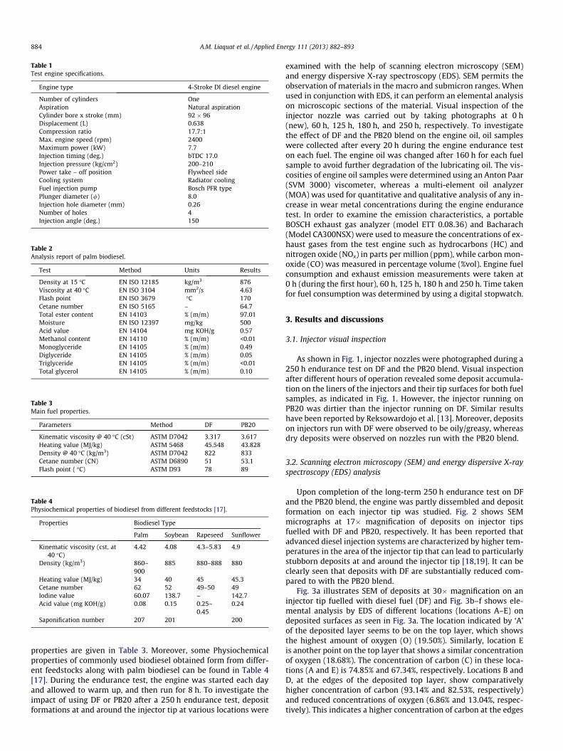
Fig. 3a illustrates SEM of deposits at 30� magnification on aninjector tip fuelled with diesel fuel (DF) and Fig. 3b–f shows ele-mental analysis by EDS of different locations (locations A–E) ondeposited surfaces as seen in Fig. 3a. The location indicated by ‘A’of the deposited layer seems to be on the top layer, which showsthe highest amount of oxygen (O) (19.50%). Similarly, location Eis another point on the top layer that shows a similar concentrationof oxygen (18.68%). The concentration of carbon (C) in these loca-tions (A and E) is 74.85% and 67.34%, respectively. Locations B andD, at the edges of the deposited top layer, show comparativelyhigher concentration of carbon (93.14% and 82.53%, respectively)and reduced concentrations of oxygen (6.86% and 13.04%, respec-tively). This indicates a higher concentration of carbon at the edges
Fig. 1. Photographic view of injector nozzles during the endurance test.
Fig. 2. SEM micrographs of deposited injector tips fuelled with (a) DF (diesel as baseline fuel) and (b) PB20 (20% palm biodiesel in diesel).
A.M. Liaquat et al. / Applied Energy 111 (2013) 882–893 885
of the deposited layer. On the other hand, location C shows thepresence of base metal (67.42% Fe) rather than a higher amountof deposition (carbon: 12.82% and oxygen: 8.43%). This indicatesthat in case of DF, the formation of deposition does not present auniformly thick layer of carbon. Generally, in baseline tests withDF, deposit accumulation at and around the injector tip did not sig-nificantly interfere with the nozzle holes. The elemental composi-tion of the deposits predominantly consisted of carbon (C) andoxygen (O) and some trace amounts of different elements. At high-er temperatures, carbon deposits are usually formed via two differ-ent routes: decomposition of hydrocarbons to elemental carbonand hydrogen; or polymerization/condensation of hydrocarbonspecies into larger polynuclear aromatic hydrocarbons (PAHs) thatthen nucleate and grow to become carbonaceous deposit. In thespectra, different metal elements were detected from the formeddeposition. In fact, many engine parts such as: (i) static compo-nents: fuel tank, filter, fuel pump injector housing, fuel line, ex-haust system, cylinder liner, etc. and (ii) dynamic components:piston, piston rings, inlet and exhaust valve, fuel pumps and filtersplunger, connecting rod, etc. may directly come in contact withfuel and engine oil. The most common metallic elements foundin deposit including aluminum (Al), chromium (Cr), copper (Cu),iron (Fe), zinc (Zn), lead (Pb), etc. could be due to wear, corrosionand tribo-corrsoion of the engine components. These metal parti-
cles are washed away lubricating oil as well as fuel. As the high-pressure pump is lubricated by engine oil, a possible source ofthe lubricant was transport of trace amounts into the fuel. In thisregard, the presence of zinc (Zn) and sulfur (S) at all locations ex-cept location B indicate that the deposit may be linked to potentialcontamination from the metal contaminated lubricant. Theappearance of iron (Fe) and chromium (Cr) at location C is due tonozzle material, whereas at location E the appearance of iron (Fe)is an artifact of beam penetration to the metal surface. However,the origin of tungsten (W) at locations C and E, and nitrogen (N)at location C could not be clarified.
Fig. 4a shows a magnified SEM image of deposits on an injectortip fuelled with PB20 at 30�magnification and Fig. 4b–f shows ele-mental analysis by EDS at different locations (locations A–E) on thedeposited surfaces shown in Fig. 4a. It can be seen in Fig. 4a thatrelatively thick and overlapping deposits are formed at tip andaround the injection hole exit along with shrinkage in the diameterof the injector nozzle hole. Moreover some nozzle holes are com-pletely closed by apparently the same deposits. All locations ofthe deposited layer indicated by locations A–E show higher con-centration of carbon. In this regard, concentration of carbon atthese locations is found as: 77.51% at location A, 69.73% at locationB, 85.17% at C, 79.86% at location D and 74.32% at location E respec-tively. However, concentration of oxygen at these locations is
Fig. 3. Magnified SEM micrographs of the deposited injector tips fuelled by DF and related elemental analysis of the different locations (locations A–E).
886 A.M. Liaquat et al. / Applied Energy 111 (2013) 882–893
found as: 18.22% at location A, 17.47% at location B, 14.83% at C,16.14% at location D and 21.39% at location E respectively. More-over, appearance of some other elements given below could notbe clarified such as: sodium (Na) and silicon (Si) at location A, so-dium (Na) and silicon (Si) at location B, sodium (Na) and silicon (Si)
at locations D and E respectively. It is noted that few metal ele-ments were found in diesel fuelled engine deposition while notin BP20. This demonstrates that BP20 seems to provide betterlubricity as compared to DF. It has been reported that higher vis-cosity and low volatility of biodiesel fuel result in poor fuel atom-
Fig. 4. Magnified SEM micrographs of the deposited injector tips fuelled by PB20 and related elemental analysis of the different locations (locations A–E).
A.M. Liaquat et al. / Applied Energy 111 (2013) 882–893 887
ization and air/fuel mixing due to the formation of the larger size offuel droplets during fuel atomization in engines [20,21]. Ignitiondelay is one of the parameters that is effected due to bigger size
of fuel droplets during the combustion process. The ignition delayincreases for higher viscosity fuel compared to the lower viscosityfuel due to its droplets requiring more time to be vaporized. Thus
888 A.M. Liaquat et al. / Applied Energy 111 (2013) 882–893
the tendency of deposit formation rate may increase [20]. Decom-position of biodiesel occurs at higher temperatures, therefore thepossibility exists for the biodiesel to be decomposed during theignition delay period, resulting in injector tip deposits. It was re-ported that deposit of biodiesel was basically composed of volatilesubstances, high boiling point substances, oxidizing substances,carbonization substances, and residual ashes in different propor-tions [22]. These could be related to unstability of biodiesel athigher temperature. Further study should be done in order tounderstand the effect of temperature on thermal stability of palmbiodiesel.
3.3. Lubricating oil analysis
Engine lubricating oil plays a very important role in IC engines.It consists of a complex mixture of hydrocarbons and is a combina-tion of base oils and additives. Lubricants are used primarily to re-duce friction and lessen the wear of various sliding and rotatingcomponents in the engine and to keep the different elements clean,acting as detergents, dispersant agents, anti-oxidants, viscositymodifiers, etc. [16,23]. In order to investigate its effect on the en-gine oil during the endurance tests carried out on DF and thePB20 blend, lubricating oil samples were collected after every20 h of operation. However engine oil was changed after 160 hoperation for each fuel sample to avoid further degradation oflubricating oil as per applicable range limits described by Kalamet al. [24]. The results of the investigations are presented in the fol-lowing sections.
3.3.1. ViscosityViscosity is one of the most important properties of engine
lubricating oils. Higher viscosity indicates that the lubricant isdeteriorating from either oxidation or contamination, while a de-crease usually indicates dilution of the lubrication oil [25]. Viscos-ity was determined at 40 �C and 100 �C. Viscosity determined at100 �C was thought to be close to the average oil temperature dur-ing engine operation [13]. It can be seen in Fig. 5a and b that therewas a decrease in oil viscosity at both 40 �C and 100 �C whether theengine was fuelled with DF or PB20 during the endurance test. Thisdecrease in lubricating oil viscosity can most likely be attributed tofuel dilution of the crankcase oil. However, the engine endurancetest carried out with PB20 showed a more pronounced reductionin engine lubricating oil viscosity compared to DF. The reductionin viscosity of the engine oil samples during the endurance testmight increase wear between the engine’s moving parts and re-duce engine life [26]. It has been reported that un-burnt biodiesel
Fig. 5. Kinematic viscosity of the engine oil at (a) 4
blend passing into the crankcase may dilute lubricating oil viscos-ity over time, reducing lubricant film thickness and ultimatelyincreasing component wear in the oil [13]. In addition, it has beenalso reported that higher viscosity of the fuel, decreases the coneangle of fuel spray and increases the diameter of fuel dropletsand their penetration in the combustion chamber. Finally, the li-quid of fuel spray can touch the combustion chamber wall andthe piston surface, causing the engine oil dilution along with car-bon deposits [27]. Moreover, excessive engine oil dilution has thepotential to create several problems, such as reduced oil perfor-mance and durability and catalyst poisoning [28]. While keepingthe above facts in mind, it can be seen in Fig. 5a and b that a greaterdecrease in lubricating oil viscosity was observed when engine wasfuelled with PB20 than with DF.
3.3.2. DensityMeasurements of engine oil density during long term endur-
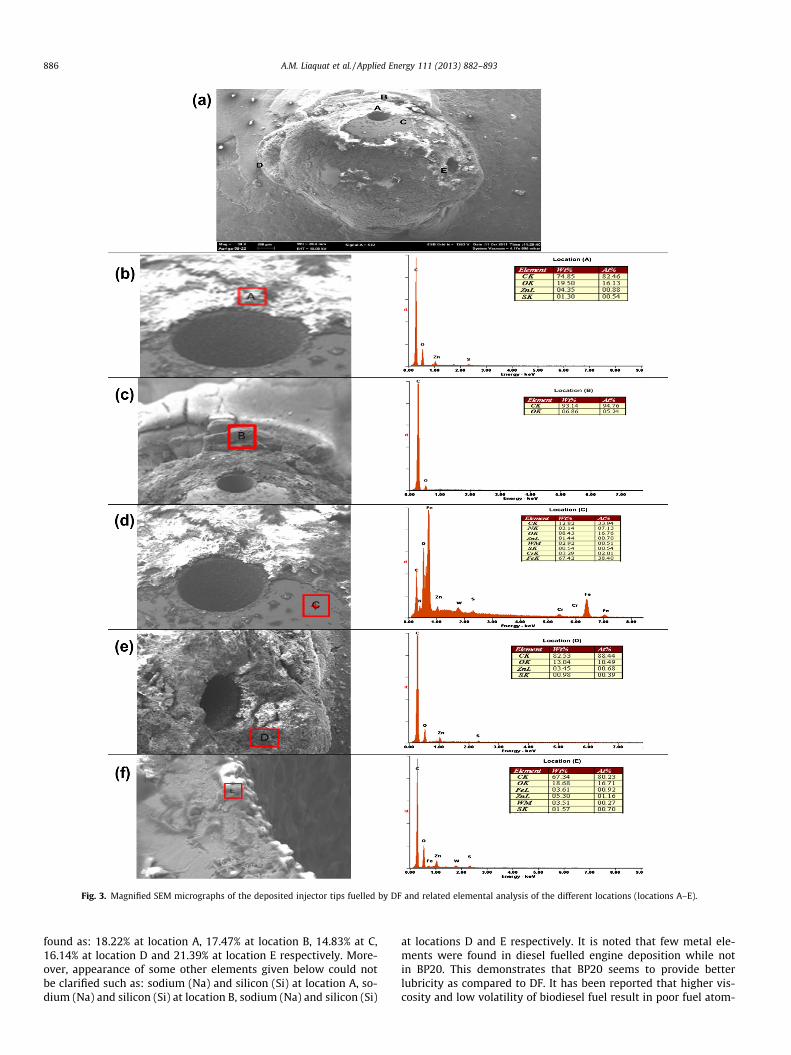
ance test provide necessary information regarding contaminationwith wear metals and dilution of the engine oil with fuel. The den-sity of the used engine oil increases mainly owing to the additionof wear debris, fuel dilution, and increased moisture content[29]. As shown in Fig. 6, the density of the engine oil samples pre-sents an increasing trend with usage. First, the wear of engine partsis faster and dilution with fuel also starts. Thus, the combined ef-fect of these factors influences the rate of increase in the densityin the engine oil more in the case of the engine running with thePB20 blend than the run with DF.
3.3.3. Analysis of lubricating oil contaminationEngine oil is basically contaminated due to wear of different en-
gine components. In diesel engines, the most critical wear compo-nents are cylinder liner, piston rings, piston and piston pins,bearing, cam, tappet, crankshaft journals, valve guides, valve sys-tems, etc [15]. In an engine lubrication system, wear particles al-ways remain in suspension in the engine oil. Therefore, weardebris originate from different components in engine and arewashed away by lubricants and finally get accumulated in the oilsump. Moreover regarding the biodiesel fuels, it has been reportedthat oxygen available in fuels may decrease exhaust emissions butmay also lead to more wear than fuels with high sulfur content.Biodiesel consisting of oxygen and unsaturated fatty acids entersinto a chemical reaction with the metal surfaces they come in con-tact with; thus, oxidation and wear may occur on the metal sur-faces [10]. Therefore, during engine endurance tests, theconcentration of metallic particles available in the engine oil pro-vides important information about wear rate and the source of ele-
0 �C and (b) 100 �C during the endurance test.
Fig. 6. Density of the engine oil during the endurance test.
A.M. Liaquat et al. / Applied Energy 111 (2013) 882–893 889
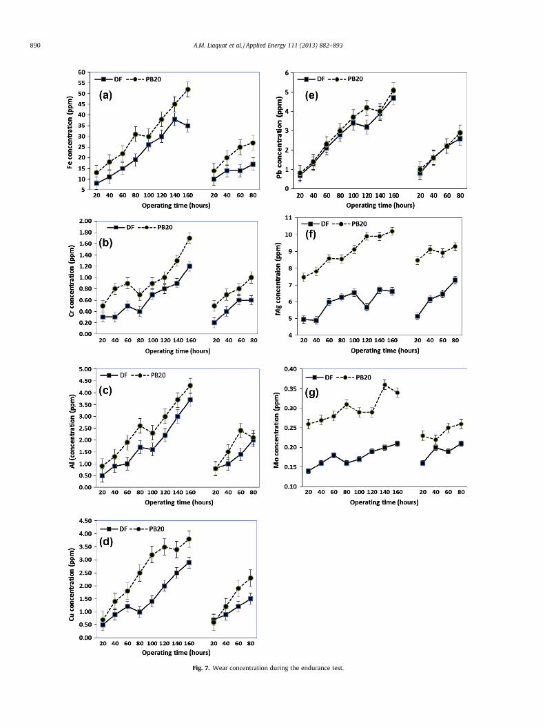
ments. Hence metal analysis of lubricating oil gives a fair idea ofthe wear on vital components in the engine. Thus, the engine con-dition at that stage can be predicted [30,31]. Fig. 7 shows variouswear particles available in the engine lubrication oil during theendurance tests, when the engine was fuelled with either DF orPB20. However, it was determined that no engine oil sample ex-ceeded the warning level suggested in [7].
3.3.3.1. Iron (Fe). In wear, iron debris originates from various en-gine components such as the piston ring, cylinder head, piston,rings, valves, gears, shafts, rust and crankshaft [15]. In fact asshown in Fig. 7a, the iron concentration in engine oil sampleswas higher when the engine was fuelled with PB20 compared toDF. The highest level of iron concentration was obtained withPB20 (52 ppm) followed by DF (38 ppm).
3.3.3.2. Chromium (Cr). In IC engines, the chromium in wear debriscould be because of wear to the cylinder liner, compression rings,gears, crankshaft and bearing [29]. Inside the cylinder, chromiumis found in very small amounts but its strength is high; therefore,as can be seen in Fig. 7b, a very small amount was present in theengine oil. The maximum chromium concentration in the engineoil was 1.7 ppm with PB20 followed by 1.2 with DF.
3.3.3.3. Aluminum (Al). The aluminum concentration in the engineoil indicates piston wear or ingested dust [26]. In Fig. 7c, the die-sel-fuelled engine showed less aluminum wear in comparison withPB20 run. The highest level of aluminum concentration was4.3 ppm with PB20 followed by 3.7 ppm when the engine wasrun on DF.
3.3.3.4. Copper (Cu). Copper wear in engine oil samples is one of themost significant issues for biodiesel-run engines. Copper may bepresent because of wear on the bearings, bronze, and bushing[15]. Fig. 7d shows the copper concentrations in engine oil sam-ples. The engine running on the PB20 blend showed higher concen-trations of copper in the engine oil when compared to the enginerun on DF. The maximum copper concentration in engine oil was3.8 ppm when the engine was fuelled with PB20 but 2.9 with DF.
3.3.3.5. Lead (Pb). The most probable sources of lead in wear debrisis due to wear on bearings and contributions from paints andgrease [29]. Fig. 7e shows lead concentrations in the engine oilwhen the engine was running on either DF or PB20. During theendurance test carried out with the PB20 blend, it showed slightlyhigher wear debris than with DF. The highest level of lead was
5.1 ppm in the case of PB20 and 4.7 ppm when engine was runon DF.
3.3.3.6. Magnesium (Mg). The magnesium in wear debris may bedue to wear on the bearing, gearbox housing and additive deple-tion [29]. Fig. 7f shows that the engine fuelled with the PB20 blendpresented higher concentrations of magnesium in the engine oilcompared to DF. The highest level of magnesium observed was10.2 ppm when the engine was fuelled with PB20, followed by6.71 ppm when it was fuelled with DF.
3.3.3.7. Molybdenum (Mo). Fig. 7g shows molybdenum concentra-tions in the engine oil. The concentrations of this element werefound to be very low, indicating a very small influence of this ele-ment on engine materials and wear. However, it can clearly be seenfrom Fig. 7g that the molybdenum concentration in the engine oilwas higher when the engine was run on PB20.
3.4. Engine fuel economy and exhaust gas emissions
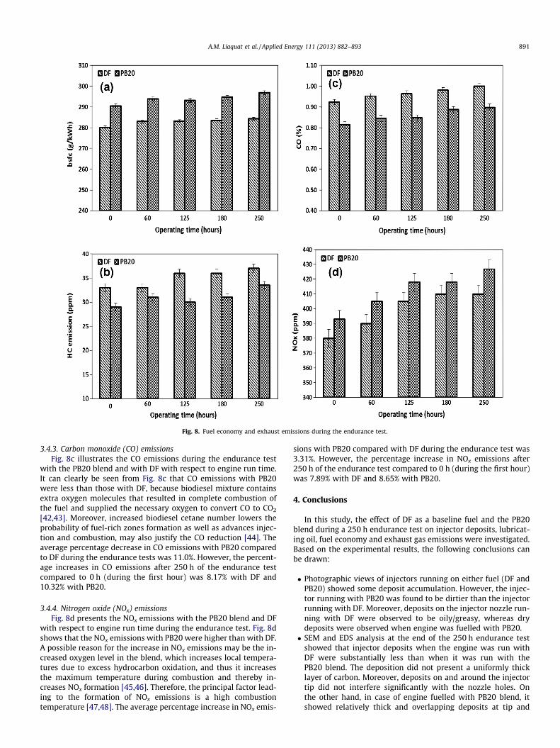
During the 250 h endurance test, engine brake specific fuel con-sumption (bsfc) and exhaust gas emissions such as HC, CO and NOx
shown in Fig. 8 were measured to investigate the effect of DF andPB20 blend due to deposit build up on injector nozzle. It has beenreported that the formation of deposits within the holes of theinjector nozzle or on the outside of the injector tip may have an ad-verse effect on overall system performance [3]. Deposits availablepresent inside spray holes of diesel injector are known to reducethe flow of the fuel whereas deposits on the nozzle tip can leadto a distortion of the optimum spray pattern [10]. Thus the injectorcarbon deposits cause many operational problems, includingexcessive smoke emissions, loss of power, poor fuel economy, de-graded emissions, excessive engine noise, rough engine operation,and poor drivability [32].
3.4.1. Brake-specific fuel consumption (bsfc)Engine bsfc with respect to engine run time during the endur-
ance tests is shown in Fig. 8a. It can clearly be seen from Fig. 8athat bsfc with the PB20 blend was higher compared to DF. This in-creased fuel consumption for the PB20 blend is due to the oxygencontent of the fuel, resulting in a lower heating value [33–35].Therefore, in order to provide the same engine output, more fuelmass flow rate is required due to lower energy content of biodieselwhich results in higher specific fuel consumption [36]. The averagepercentage increase in bsfc for PB20 compared to DF during theendurance tests was 3.88%. However, the percentage increase inbsfc after 250 h compared to 0 h (during the first hour) was1.49% with DF and 2.22% with PB20.
3.4.2. Hydrocarbon (HC) emissionsFig. 8b shows HC emissions with respect to engine run time
during the endurance tests. The values of unburned hydrocarbonemissions in the case of the PB20 blend were less than those withDF. The decreased trend in HC emissions from the CI engine com-pared to DF may be due to better combustion of biodiesel blenddue to presence of oxygen [34,37,38]. Moreover, it has been re-ported that the higher cetane number of biodiesel reduces thecombustion ignition delay, and such a reduction has also been re-lated to decreases in HC emissions [39–41]. During the endurancetests, the average percentage decrease in HC emissions with PB20compared to DF was 11.71%. However, the percentage increase inHC emissions after 250 h of the endurance test compared to 0 h(during the first hour) were 12.12% with DF and 15.52% withPB20. The increases in HC emissions after 250 h of the endurancetest may be due to insufficient combustion caused by depositbuildup and injector clogging [11] .
Fig. 7. Wear concentration during the endurance test.
890 A.M. Liaquat et al. / Applied Energy 111 (2013) 882–893
Fig. 8. Fuel economy and exhaust emissions during the endurance test.
A.M. Liaquat et al. / Applied Energy 111 (2013) 882–893 891
3.4.3. Carbon monoxide (CO) emissionsFig. 8c illustrates the CO emissions during the endurance test
with the PB20 blend and with DF with respect to engine run time.It can clearly be seen from Fig. 8c that CO emissions with PB20were less than those with DF, because biodiesel mixture containsextra oxygen molecules that resulted in complete combustion ofthe fuel and supplied the necessary oxygen to convert CO to CO2
[42,43]. Moreover, increased biodiesel cetane number lowers theprobability of fuel-rich zones formation as well as advances injec-tion and combustion, may also justify the CO reduction [44]. Theaverage percentage decrease in CO emissions with PB20 comparedto DF during the endurance tests was 11.0%. However, the percent-age increases in CO emissions after 250 h of the endurance testcompared to 0 h (during the first hour) was 8.17% with DF and10.32% with PB20.
3.4.4. Nitrogen oxide (NOx) emissionsFig. 8d presents the NOx emissions with the PB20 blend and DF
with respect to engine run time during the endurance test. Fig. 8dshows that the NOx emissions with PB20 were higher than with DF.A possible reason for the increase in NOx emissions may be the in-creased oxygen level in the blend, which increases local tempera-tures due to excess hydrocarbon oxidation, and thus it increasesthe maximum temperature during combustion and thereby in-creases NOx formation [45,46]. Therefore, the principal factor lead-ing to the formation of NOx emissions is a high combustiontemperature [47,48]. The average percentage increase in NOx emis-
sions with PB20 compared with DF during the endurance test was3.31%. However, the percentage increase in NOx emissions after250 h of the endurance test compared to 0 h (during the first hour)was 7.89% with DF and 8.65% with PB20.
4. Conclusions
In this study, the effect of DF as a baseline fuel and the PB20blend during a 250 h endurance test on injector deposits, lubricat-ing oil, fuel economy and exhaust gas emissions were investigated.Based on the experimental results, the following conclusions canbe drawn:
� Photographic views of injectors running on either fuel (DF andPB20) showed some deposit accumulation. However, the injec-tor running with PB20 was found to be dirtier than the injectorrunning with DF. Moreover, deposits on the injector nozzle run-ning with DF were observed to be oily/greasy, whereas drydeposits were observed when engine was fuelled with PB20.� SEM and EDS analysis at the end of the 250 h endurance test
showed that injector deposits when the engine was run withDF were substantially less than when it was run with thePB20 blend. The deposition did not present a uniformly thicklayer of carbon. Moreover, deposits on and around the injectortip did not interfere significantly with the nozzle holes. Onthe other hand, in case of engine fuelled with PB20 blend, itshowed relatively thick and overlapping deposits at tip and
892 A.M. Liaquat et al. / Applied Energy 111 (2013) 882–893
around the injection hole exit along with shrinkage in the diam-eter of the injector nozzle hole. Moreover some nozzle holes arecompletely closed by apparently the same deposits. All loca-tions of the deposited layer showed higher concentration ofcarbon.� During the endurance test, the viscosity of the lubricating oil
with respect to engine operating time at 40 �C and 100 �C wasdecreased when the engine was fuelled with DF and PB20. How-ever, when PB20 was used, it presented a greater reductioncompared with DF.� The density of the engine oil during the endurance tests showed
increased with both fuels. However, the increase in the engineoil density was greater when the engine was fuelled withPB20blend.� Similarly, the concentrations of metallic particles available in
the engine oil during the endurance test were higher whenthe engine was fuelled with PB20 compared to DF.� Engine bsfc was higher with PB20 compared to DF. However,
during the endurance tests, the percentage increase in bsfc after250 h compared to 0 h (during the first hour) was 1.49% for DFand 2.22% for PB20.� The average emissions of HC and CO were decreased with PB20
compared to DF. However, the percentage increases in HC emis-sions after 250 h compared to 0 h (during the first hour) were12.12% for DF and 15.52% for PB20. Similarly, in the case ofCO emissions, the percentage increase was 8.17% with DF and10.32% with PB20.� Average NOx emission increased with PB20 compared to DF.
However, the percentage increase in NOx emissions after250 h compared to 0 h (during the first hour) was 7.89% withDF and 8.65% with PB20.
Acknowledgement
The authors would like to acknowledge University of Malaya forthe financial support through Project No. UM.C/HIR/MOHE/ENG/O7and PPP, No. PS114/ 2010A
References
[1] Macor A, Avella F, Faedo D. Effects of 30% v/v biodiesel/diesel fuel blend onregulated and unregulated pollutant emissions from diesel engines. ApplEnergy 2011;88:4989–5001.
[2] Caprotti R, Bhatti N, Balfour G. Deposit control in modern diesel fuel injectionsystems. SAE International paper No. 2010-01-2250; 2010.
[3] Richards P, Birgel A, Aleiferis P, Ladommatos N, Orlovic A, Lafon V, et al.Deposit formation in the holes of diesel injector nozzles: a critical review. SAEPaper Number: 2008-01-2383; 2008.
[4] Sidibé SS, Blin J, Vaitilingom G, Azoumah Y. Use of crude filtered vegetable oilas a fuel in diesel engines state of the art: literature review. Renew Sust EnergyRev 2010;14:2748–59.
[9] Pehan S, Jerman MS, Kegl M, Kegl B. Biodiesel influence on tribologycharacteristics of a diesel engine. Fuel 2009;88:970–9.
[10] Celik I, Aydin O. Effects of B100 biodiesel on injector and pump piston. Tribol T2011;54:424–31.
[11] Caprotti R, Breakspear A, Klaua T, Weiland P, Graupner O, Bittner M. RMEbehavior in current and future diesel fuel FIE’s. SAE Ppaer No. 2007-01 3982;2007.
[12] Sinha S, Agarwal AK. Experimental investigation of the effect of biodieselutilization on lubricating oil degradation and wear of a transportation CIDIengine. J Eng Gas Turb Power 2010;132:42801–11.
[13] Reksowardojo IK, Bui HN, Sok R, Kilgour AJ, Brodjonegoro TP, Soerawidjaja TH,et al. The effect of biodiesel fuel rubber (hevea brasiliensis) seed oil on a directinjection (DI) diesel engine. Asean Eng J 2011;1:65–81.
[14] Agarwal AK. Biofuels (alcohols and biodiesel) applications as fuels for internalcombustion engines. Prog Energy Combust 2007;33:233–71.
[15] Haseeb ASMA, Fazal MA, Jahirul MI, Masjuki HH. Compatibility of automotivematerials in biodiesel: a review. Fuel 2011;90:922–31.
[16] Basinger M, Reding T, Rodriguez-Sanchez FS, Lackner KS, Modi V. Durabilitytesting modified compression ignition engines fueled with straight plant oil.Energy 2010;35:3204–20.
[17] Leung DYC, Wu X, Leung MKH. A review on biodiesel production usingcatalyzed transesterification. Appl Energy 2010;87:1083–95.
[18] Shu G, Dong L, Liang X. A review of experimental studies on deposits in thecombustion chambers of internal combus. Int J Eng Res 2012.
[19] Leedham A, Caprotti R, Graupner O, Klaua T. Impact of fuel additives on dieselinjector deposits. SAE Paper No. 2004-01-2935; 2004.
[20] Yusmady MA. Diesel and bio-diesel fuel deposits on a hot wall surface:department of mechanical system engineering. Japan: GUNMA University;2009.
[21] Zhang W, Yuan W, Zhang X, Coronado M. Predicting the dynamic andkinematic viscosities of biodiesel–diesel blends using mid- and near-infraredspectroscopy. Appl Energy 2012;98:122–7.
[22] Mohamed Arifin Y, Furuhata T, Saito M, Arai M. Diesel and bio-diesel fueldeposits on a hot surface. JSAE Trans 2008;39(3):207–13.
[26] Wander PR, Altafini CR, Colombo AL, Perera SC. Durability studies of mono-cylinder compression ignition engines operating with diesel, soy and castor oilmethyl esters. Energy 2011;36:3917–23.
[27] Pandey RK, Rehman A, Sarviya RM. Impact of alternative fuel properties on fuelspray behavior and atomization. Renew Sust Energy Rev 2012;16:1762–78.
[28] Thornton MJ, Alleman TL, Luecke J, McCormick RL. Impacts of biodiesel fuelblends oil dilution on light-duty diesel engine operation. SAE paper no. 2009-01-1790; 2009.
[29] Agarwal AK, Dhar A. Karanja oil utilization in a direct-injection engine bypreheating. Part 2: Experimental investigations of engine durability andlubricating oil properties. Proc Inst Mech Eng, Part D: J Automob Eng2010;224:85–97.
[30] Pandey AK, Nandgaonkar MR. Experimental investigation of the effect ofesterified karanja oil biodiesel on performance, emission and engine wear of amilitary heavy duty, 118 kW, turbocharged CIDI engine. JSAE 20119011, SAE2011-01-1945; 2011.
[31] Kalam MA, Majsuki HH. Use of an additive in biofuel to evaluate emissions,engine component wear and lubrication characteristics. Proc Inst Mech Eng,Part D: J Automob Eng 2002;216:751–7.
[32] Sapienza RS, Butcher T, Krushna CR, Gaffney J. In chemistry of enginecombustion deposits. New York: Plenum Press; 1985.
[33] Huang J, Wang Y, Qin J-B, Roskilly AP. Comparative study of performance andemissions of a diesel engine using Chinese pistache and jatropha biodiesel.Fuel Process Technol 2010;91:1761–7.
[34] Dhar A, Kevin R, Agarwal AK. Production of biodiesel from high-FFA neem oiland its performance, emission and combustion characterization in a singlecylinder DICI engine. Fuel Process Technol 2012;97:118–29.
[35] An H, Yang WM, Chou SK, Chua KJ. Combustion and emissions characteristicsof diesel engine fueled by biodiesel at partial load conditions. Appl Energy2012;99:363–71.
[36] Çelikten _I, Mutlu E, Solmaz H. Variation of performance and emissioncharacteristics of a diesel engine fueled with diesel, rapeseed oil andhazelnut oil methyl ester blends. Renew Energy 2012;48:122–6.
[37] Shivakumar, Srinivasa Pai P, Shrinivasa Rao BR. Artificial neural network basedprediction of performance and emission characteristics of a variablecompression ratio CI engine using WCO as a biodiesel at different injectiontimings. Appl Energy 2011;88:2344–54.
[38] Gumus, Sayin C, Canakci M. The impact of fuel injection pressure on theexhaust emissions of a direct injection diesel engine fueled with biodiesel–diesel fuel blends. Fuel 2012;95:486–94.
[39] Monyem A, Van Gerpen JH, Canakci M. The effect of timing and oxidation onemissions from biodiesel-fueled engines. Trans ASAE 2001;44:35–42.
[40] Abd-Alla GH, Soliman HA, Badr OA, Abd-Rabbo MF. Effects of diluentadmissions and intake air temperature in exhaust gas recirculation on theemissions of an indirect injection dual fuel engine. Energy Convers Manage2001;42:1033–45.
[41] Rao PV. Experimental investigations on the influence of properties of jatrophabiodiesel on performance, combustion, and emission characteristics of a DI–CIengine. World Acad Sci, Eng Technol 2011;75:855–68.
[42] Gumus M, Kasifoglu S. Performance and emission evaluation of a compressionignition engine using a biodiesel (apricot seed kernel oil methyl ester) and itsblends with diesel fuel. Biomass Bioenergy 2010;34:134–9.
A.M. Liaquat et al. / Applied Energy 111 (2013) 882–893 893
[43] Ganapathy T, Gakkhar RP, Murugesan K. Influence of injection timing onperformance, combustion and emission characteristics of Jatropha biodieselengine. Appl Energy 2011;88:4376–86.
[44] Rizwanul Fattah IM, Masjuki HH, Liaquat AM, Ramli R, Kalam MA, RiazuddinVN. Impact of various biodiesel fuels obtained from edible and non-edible oilson engine exhaust gas and noise emissions. Renew Sust Energy Rev2013;18:552–67.
[45] Özener O, Yüksek L, Ergenç AT, Özkan M. Effects of soybean biodiesel on a DIdiesel engine performance, emission and combustion characteristics. Fuel2013 (in press).
[46] Liaquat AM, Masjuki HH, Kalam MA, Varman M, Hazrat MA, Shahabuddin M,et al. Application of blend fuels in a diesel engine. Energy Proc2012;14:1124–33.
[47] Ndayishimiye P, Tazerout M. Use of palm oil-based biofuel in the internalcombustion engines: performance and emissions characteristics. Energy2011;36:1790–6.
[48] Hirkude JB, Padalkar AS. Performance and emission analysis of a compressionignition: engine operated on waste fried oil methyl esters. Appl Energy2012;90:68–72.


![EFFECT OF DIESEL-BIODIESEL-ETHANOL BLEND ON … · In previous investigations [22] it was found that diesel-ethanol fuel blend up to 30% of etha-nol fuel (EF) is possible to stabile](https://static.documents.pub/doc/80x56/5f1040b17e708231d448318c/effect-of-diesel-biodiesel-ethanol-blend-on-in-previous-investigations-22-it-was.jpg)