╣JANA KNOWLEDGE ● VALUES ● SUCCESS Jana Laboratories Inc. 280B Industrial Pkwy S. Aurora, Ontario L4G 3T9 Ph: 905-726-8550 Fax: 905-726-8609 www.janalab.com June 30, 2010 TECHNICAL REPORT Impact of Potable Water Disinfectants on PE Pipe
Transcript
╣JANA
KNOWLEDGE ● VALUES ● SUCCESS
Jana Laboratories Inc. 280B Industrial Pkwy S. Aurora, Ontario L4G 3T9 Ph: 905-726-8550 Fax: 905-726-8609 www.janalab.com
June 30, 2010
TECHNICAL REPORT
Impact of Potable Water Disinfectants on PE Pipe
Technical Report – Impact of Potable Water Disinfectants on PE Pipe Page 1 of 34
╣JANA
KNOWLEDGE ● VALUES ● SUCCESS
Jana Laboratories Inc. 280B Industrial Pkwy S. Aurora, Ontario L4G 3T9 Ph: 905-726-8550 Fax: 905-726-8609 www.janalab.com
Executive Summary
Polyethylene (PE) piping materials have been used in potable water applications for more than 50 years with considerable success and have enjoyed a consistently high satisfaction rating from Water Utilities. Since the introduction of these first materials, there has been a significant evolution in material performance. To demonstrate and validate the long-term performance of the newer generation PE piping systems in potable water applications, the industry has been proactively working to develop accelerated test and analysis methodologies through the last decade that will enable projecting long-term performance based on accelerated testing and an understanding of the specific end-use environment. This report provides a summary of the current state of those efforts, detailing the mechanisms of long-term aging of PE materials in potable water applications, examining the primary end-use and product factors impacting the long-term aging mechanisms, and reporting on a methodology to project long-term performance of PE piping materials in potable water applications. The methodology and the resulting performance projections are validated based on the currently available data. The use and limitations of the commonly applied analytical methodologies of Oxidation Induction Time and Fourier Transform Infra-Red spectroscopy are also examined. It is seen that extensive research has been conducted on the long-term aging mechanisms of PE pipe materials and that, from this research, a relatively complete picture of the mechanisms of long-term aging has been developed along with methodologies for characterizing this performance. The primary methodology developed for forecasting long-term aging shows that specific performance is a function of the water quality, water temperature and operating stress, all of which can vary by specific utility. For the Case Study utilities examined, the current models project that high performance PE piping materials can conservatively provide greater than 100 years resistance to chlorine and chloramines treated potable water through the vast majority of potable water systems when properly designed and installed. The models also explain the performance observed in the limited instances where performance issues in small diameter service line tubing have been observed in terms of the specific aggressiveness of those applications.
Technical Report – Impact of Potable Water Disinfectants on PE Pipe Page 2 of 34
╣JANA
KNOWLEDGE ● VALUES ● SUCCESS
Jana Laboratories Inc. 280B Industrial Pkwy S. Aurora, Ontario L4G 3T9 Ph: 905-726-8550 Fax: 905-726-8609 www.janalab.com
Report No.: Impact of Potable Water Disinfectants of PE Pipe P.O. No.: C. Rubeiz Client: Plastics Pipe Institute, Inc.
105 Decker Court, Suite 825 Irving, TX 75062 U.S.A.
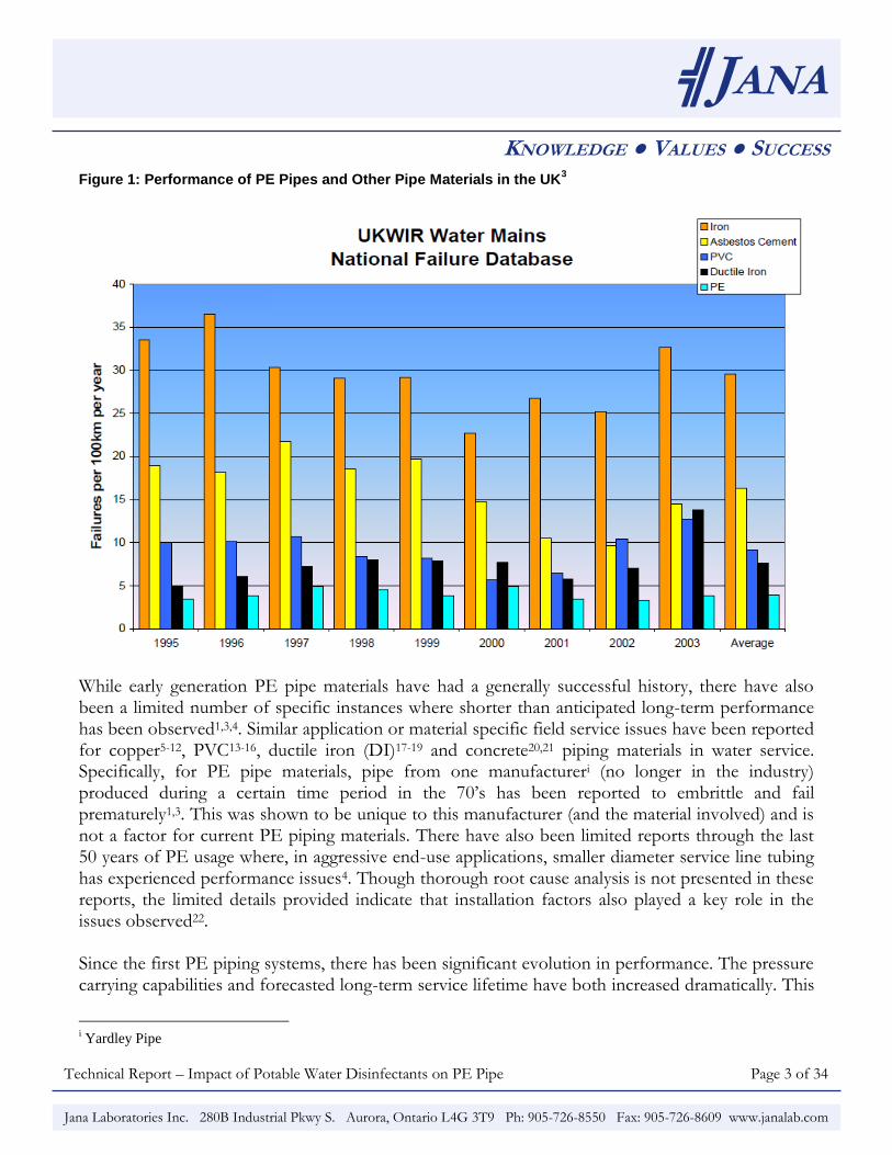
Date of Issue: June 30, 2010 1.0 Introduction Polyethylene (PE) piping materials have enjoyed a long and successful history in gas and water piping applications. In the North American gas distribution industry, PE pipe is the material of choice, having grown to a 95% market share in new distribution piping networks. In the European water industry, PE pipe dominates the market at 65% share. Specifically, in the UK, PE pipe holds almost the entire market with an 85% share. In the North American water industry, PE pipe holds a much smaller, though growing, share of the market. The first PE water piping systems in the US were installed over 50 years ago. Since then, PE piping systems have enjoyed a consistently high satisfaction rating from Water Utilities in North America and Europe. Chambers1 first reported on the performance of these early PE piping materials in water service applications in 1984. The report was based on data from an American Water Works Association (AWWA) survey combined with telephone interviews, site visits and laboratory analysis. At the time of the survey, the utilities had been using PE pipe for as long as 20 years. Overall satisfaction with PE pipe was 95% (with the exclusion of pipe from one manufacturer). Thompson and Jenkins conducted an AWWA Research Foundation sponsored survey entitled „Review of Water Industry Plastic Pipe Practices‟2, published in 1987. The findings were similar to those reported by Chambers, with median satisfaction ratings of 85 to 90% for both PE and polyvinyl chloride (PVC). More recent data has been reported for the UK water industry (where PE pipe usage rates are currently at 85%) showing that PE pipe has the lowest failure rate of all water distribution piping materials, as shown in Figure 1. Similar experience was recently reported by the Arhus Water Company in Denmark at the Plastics Pipes XIII conference in Washington, DC, in October of 2006, again showing PE water pipe to have the lowest failure rates of all materials in their system3.
Technical Report – Impact of Potable Water Disinfectants on PE Pipe Page 3 of 34
╣JANA
KNOWLEDGE ● VALUES ● SUCCESS
Jana Laboratories Inc. 280B Industrial Pkwy S. Aurora, Ontario L4G 3T9 Ph: 905-726-8550 Fax: 905-726-8609 www.janalab.com
Figure 1: Performance of PE Pipes and Other Pipe Materials in the UK3
While early generation PE pipe materials have had a generally successful history, there have also been a limited number of specific instances where shorter than anticipated long-term performance has been observed1,3,4. Similar application or material specific field service issues have been reported for copper5-12, PVC13-16, ductile iron (DI)17-19 and concrete20,21 piping materials in water service. Specifically, for PE pipe materials, pipe from one manufactureri (no longer in the industry) produced during a certain time period in the 70‟s has been reported to embrittle and fail prematurely1,3. This was shown to be unique to this manufacturer (and the material involved) and is not a factor for current PE piping materials. There have also been limited reports through the last 50 years of PE usage where, in aggressive end-use applications, smaller diameter service line tubing has experienced performance issues4. Though thorough root cause analysis is not presented in these reports, the limited details provided indicate that installation factors also played a key role in the issues observed22. Since the first PE piping systems, there has been significant evolution in performance. The pressure carrying capabilities and forecasted long-term service lifetime have both increased dramatically. This
i Yardley Pipe
Technical Report – Impact of Potable Water Disinfectants on PE Pipe Page 4 of 34
╣JANA
KNOWLEDGE ● VALUES ● SUCCESS
Jana Laboratories Inc. 280B Industrial Pkwy S. Aurora, Ontario L4G 3T9 Ph: 905-726-8550 Fax: 905-726-8609 www.janalab.com
has been driven by a proactive approach by the industry to characterize and increase system performance. It has also been seen that long-term performance in potable water applications increases with increasing pipe diameter23.
Given a successful 50 year history, the evolution in material performance and the impact of pipe diameter, coupled with a limited number of reports of performance issues in aggressive applications, the question arises: What is the true performance of today‟s PE pipe in potable water applications and how can that performance be validated and predicted for given applications? The successful history of PE water piping in Europe3 and North America1,3 provides some substantiation of PE‟s performance in potable water applications. However, looking to the performance of existing PE systems to predict the performance of the newer improved materials would provide only a conservative estimate of minimum performance. With the enhancements made to materials, formulations and manufacturing methods, the performance of current generation systems is projected to be much higher than the original PE installations. Further, examination of the overall successful performance history does not provide complete insight into those limited instances where lower than expected performance has been observed. To better answer this question, then, and to also demonstrate and validate the long-term performance of PE piping systems in potable water applications, the PE piping industry has been proactively working to develop accelerated test and analysis methodologies through the last decade that will enable projecting long-term performance based on accelerated testing and an understanding of the end-use environment. There have been several worldwide studies examining the impact of potable water on piping systems. Numerous publications charting the progress in this area in detailing the mechanisms involved24-37, the development of aggressive accelerated testing approaches26,32,38,39 and validation of the developed methodologies3,26,32,40,41 have been issued. This paper provides a summary of the current state of those efforts, detailing the mechanisms of long-term aging of PE materials in potable water applications. It examines the primary end-use and product factors impacting the long-term aging mechanisms and reports on a methodology to project long-term performance of PE piping materials in potable water applications. The methodology and the resulting performance projections are validated based on the currently available data. It is seen that extensive research has been conducted on the long-term aging mechanisms of PE pipe materials and that, from this research, a relatively complete picture of the mechanisms of long-term aging has been developed along with methodologies for characterizing this performance1,3. The primary methodology developed for forecasting long-term aging shows that performance is a function of the water quality, water temperature and operating stress and varies by utility. For the Case Study utilities examined, the current models project that high performance PE piping materials can very conservatively provide greater than 100 years resistance to chlorine and chloramine treated potable water through the majority of potable water systems when properly
Technical Report – Impact of Potable Water Disinfectants on PE Pipe Page 5 of 34
╣JANA
KNOWLEDGE ● VALUES ● SUCCESS
Jana Laboratories Inc. 280B Industrial Pkwy S. Aurora, Ontario L4G 3T9 Ph: 905-726-8550 Fax: 905-726-8609 www.janalab.com
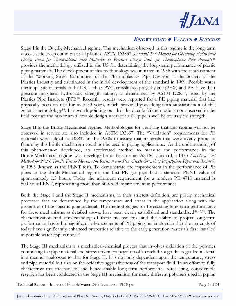
designed and installed. The models also explain the performance observed in the limited instances where performance issues in small diameter service line tubing have been observed in terms of the unique aggressiveness of those applications. 2.0 Long-Term Aging Mechanisms of PE in Potable Water Applications Clearly understanding the mechanisms of aging for any material, and hence the key factors impacting performance in end-use, is critical to understanding both how the material is best applied and in the development of methodologies for projecting long-term performance in service. To that end, research has been conducted on the long-term aging mechanisms of plastic piping materials in general42 and PE pipe materials specifically43-45. From this research a relatively complete picture of the mechanisms of long-term aging of PE piping materials has been developed along with methodologies for characterizing this performance44,46-48. The performance envelope for plastic piping materials is typically represented in terms of the log(stress) versus log(time) plot as shown in Figure 2. Three „stages‟ in the aging process are typically identified based on the three different aging mechanism typically observed. These are denoted as Stage I, Stage II and Stage III. Figure 2: Defining the Performance Envelope of Plastic Piping Materials
Log (time)
Lo
g (
str
ess)
Stage II
Stage III
Stage I
PERFORMANCE ENVELOPE
WITH APPLIED DESIGN FACTOR
Technical Report – Impact of Potable Water Disinfectants on PE Pipe Page 6 of 34
╣JANA
KNOWLEDGE ● VALUES ● SUCCESS
Jana Laboratories Inc. 280B Industrial Pkwy S. Aurora, Ontario L4G 3T9 Ph: 905-726-8550 Fax: 905-726-8609 www.janalab.com
Stage I is the Ductile-Mechanical regime. The mechanism observed in this regime is the long-term visco-elastic creep common to all plastics. ASTM D2837 Standard Test Method for Obtaining Hydrostatic Design Basis for Thermoplastic Pipe Materials or Pressure Design Basis for Thermoplastic Pipe Products46 provides the methodology utilized in the US for determining the long-term performance of plastic piping materials. The development of this methodology was initiated in 1958 with the establishment of the „Working Stress Committee‟ of the Thermoplastics Pipe Division of the Society of the Plastics Industry and culminated in the initial development of the standard in 1969. Potable water thermoplastic materials in the US, such as PVC, crosslinked polyethylene (PEX) and PE, have their pressure long-term hydrostatic strength ratings, as determined by ASTM D2837, listed by the Plastics Pipe Institute (PPI)49. Recently, results were reported for a PE piping material that had physically been on test for over 50 years, which provided good long-term substantiation of this general methodology50. It is worth pointing out that the ductile failure mode is not observed in the field because the maximum allowable design stress for a PE pipe is well below its yield strength. Stage II is the Brittle-Mechanical regime. Methodologies for verifying that this regime will not be observed in service are also included in ASTM D2837. The “Validation” requirements for PE materials were added to D2837 in the 1980s to assure that materials that were overly prone to failure by this brittle mechanism could not be used in piping applications. As the understanding of this phenomenon developed, an accelerated method to measure the performance in the Brittle-Mechanical regime was developed and became an ASTM standard, F1473 Standard Test Method for Notch Tensile Test to Measure the Resistance to Slow Crack Growth of Polyethylene Pipes and Resins47, in 1995 (known as the PENT test). To demonstrate the improvement in the performance of PE pipes in the Brittle-Mechanical regime, the first PE gas pipe had a standard PENT value of approximately 1.5 hours. Today the minimum requirement for a modern PE 4710 material is 500 hour PENT, representing more than 300-fold improvement in performance. Both the Stage I and the Stage II mechanisms, in their strictest definition, are purely mechanical processes that are determined by the temperature and stress in the application along with the properties of the specific pipe material. The methodologies for forecasting long-term performance for these mechanisms, as detailed above, have been clearly established and standardized46,47,51. The characterization and understanding of these mechanisms, and the ability to project long-term performance, has led to significant advancements of PE piping materials such that the materials of today have significantly enhanced properties relative to the early generation materials first installed in potable water applications52. The Stage III mechanism is a mechanical-chemical process that involves oxidation of the polymer comprising the pipe material and stress driven propagation of a crack through the degraded material in a manner analogous to that for Stage II. It is not only dependent upon the temperature, stress and pipe material but also on the oxidative aggressiveness of the transport fluid. In an effort to fully characterize this mechanism, and hence enable long-term performance forecasting, considerable research has been conducted in the Stage III mechanism for many different polymers used in piping
Technical Report – Impact of Potable Water Disinfectants on PE Pipe Page 7 of 34
╣JANA
KNOWLEDGE ● VALUES ● SUCCESS
Jana Laboratories Inc. 280B Industrial Pkwy S. Aurora, Ontario L4G 3T9 Ph: 905-726-8550 Fax: 905-726-8609 www.janalab.com
applications (crosslinked polyethylene26,39,53-56, polybutylene55,57-61, polysulphone62, polyacetal63,64, polyamides65, elastomers66), including PE piping materials24-37. With today‟s PE piping materials and the evolution in Stage I and, particularly, Stage II performance, the characterization of the Stage III aging mechanism is considered a key area for continuing enhancement of the long-term performance of PE piping materials in potable water applications. Consequently, the current „state-of-the-art‟ in understanding of this mechanism and the means to characterize long-term performance are the primary focus of this paper. 2.1 The Mode 3 Long-Term Aging Mechanism in PE Pipe Materials
Chung et al.24 presented a further differentiation of the „brittle‟ Stage II and Stage III mechanisms in terms of Mode 1, 2, 3 and 4 based on the potential for mechanical or mechanical-oxidative mechanisms in crack initiation and crack propagation. The different postulated mechanisms are:
Mode 4: Chemical-Mechanical Crack Initiation – Chemical-Mechanical Crack Propagation Modes 1, 3 and 4 are considered pertinent to long-term performance projections. Mode 2 is considered a theoretical curiosity that has not been observed in accelerated testing or the field. Mode 1 and Mode 4 are analogous, as the terms are generally applied, to Stage II and Stage III, respectively. The Mode 3 mechanism is observed in field aging and accelerated testing of PE piping materials in potable water applications and is, therefore, the mechanism of primary interest in long-term performance projections. Overall, the Mode 3 mechanism24 involves depletion of the stabilizers (added to PE pipe specifically to enhance long-term aging performance due to this mechanism) at the inner pipe surface, oxidation of the polymer at the inner pipe surface, initiation of a micro-crack in the degraded material and then propagation of the crack through the pipe wall via the same mechanical crack propagation mechanism observed in Stage II Slow Crack Growth (SCG). The total time to rupture for Mode 3 (tf) can, therefore, be considered in terms of the time for stabilizer depletion (tsd), the time for crack initiation (ti) and the time for crack propagation (tp) per Equation 1:
tf = tsd + ti + tp (1)
Technical Report – Impact of Potable Water Disinfectants on PE Pipe Page 8 of 34
╣JANA
KNOWLEDGE ● VALUES ● SUCCESS
Jana Laboratories Inc. 280B Industrial Pkwy S. Aurora, Ontario L4G 3T9 Ph: 905-726-8550 Fax: 905-726-8609 www.janalab.com
2.1.1 Stabilizer Consumption in Mode 3 Aging Mechanism
The time for stabilizer depletion (tsd) is considered to be a generally stress independent thermally activated process that is dependent on the stabilization of the PE and the oxidative environment. For a given compound at a given temperature this time can be considered generally constant and independent of, or at least weakly dependent on67, stress.
Several researchers have examined the depletion of stabilizers in PE pipe materials exposed to potable water environments27,29,30,53,68-72 in an effort to better understand and characterize this process. Viebke and Gedde have proposed that plastic pipe lifetimes are comprised of A, B, and C regimes corresponding to a precipitation period, a period of Fickian diffusion with chemical consumption or extraction of antioxidant, and a polymer degradation period69. Here Regimes A and B correspond to the time for stabilizer depletion (tsd) and Regime C to the degradation phase after stabilizer has been depleted. A common tool applied to examination of stabilizer depletion over time is the Oxidative Induction Time (OIT) test30,55,68,73. This test indirectly measures the level of stabilization in the pipe material through measurement of the time for oxidation to occur at highly elevated temperatures (typically 190°C or 200°C) in a pure oxygen environment. While the methodology has its limitations73, when these are considered the method can provide insight into the overall process of stabilizer depletion. It is introduced here for the discussions that follow. Regime A is a special initial period of adjustment to the service temperature (or test temperature). If the initial concentration of a stabilizer is greater than its solubility at the test or service temperature, some stabilizer will precipitate as thermal equilibrium is established. Though the precipitate remains within the polymer, it is no longer functional in the Oxidative Induction Time (OIT) test, causing an initial sharp drop in the OIT value that is not related to oxidation or consumption of the stabilizer. Regime B involves the stabilizer being consumed at the inner pipe surface. As the stabilizer concentration is reduced at the surface, a concentration gradient is established between the inner surface and the bulk polymer wall. This provides the driving force for diffusion from the bulk wall to the inner pipe surface, resulting in a constant replenishment of stabilizer at the inner pipe surface. Hoang and Lowe74 found that a 95% reduction in the antioxidant levels occurred at exposed surfaces (as determined by OIT) within the first 8% of the measured lifetime of PE pipe. In other words, pipe with only 5% of the remaining antioxidants as measured by OIT still had almost all
Technical Report – Impact of Potable Water Disinfectants on PE Pipe Page 9 of 34
╣JANA
KNOWLEDGE ● VALUES ● SUCCESS
Jana Laboratories Inc. 280B Industrial Pkwy S. Aurora, Ontario L4G 3T9 Ph: 905-726-8550 Fax: 905-726-8609 www.janalab.com
(92%) of its expected service life remaining. Regime B, with its low inner surface OIT levels, therefore, can be seen to initiate early in the overall aging process. Though stabilizer is generally depleted at the inner surface at the end of Regime B, the stabilizer level in the bulk of the pipe wall is typically still relatively high. 2.1.2 Oxidation and Crack Initiation in the Mode 3 Long-Term Aging Mechanism At the end of Regime B, the stabilizer is depleted to a level at which oxidation of the polymer can initiate, resulting in changes to the physical properties of the polymer (termed Regime C by Viebke and Gedde69). At a certain level of oxidation, which is dependent upon the applied stress on the pipe, crack initiation occurs in the oxidized material at the inner pipe bore. The overall time for degradation and crack initiation in the degraded layer is captured by ti. The level of degradation required to initiate a crack at a given stress will be a function of the physical properties of the degraded material and the applied stress. As oxidation progresses, the fracture toughness of the inner surface layer decreases and, at a certain point, for a given stress, crack initiation occurs. This crack initiation typically occurs in a thin (on the order of 50 to 150 µm) degraded layer75.
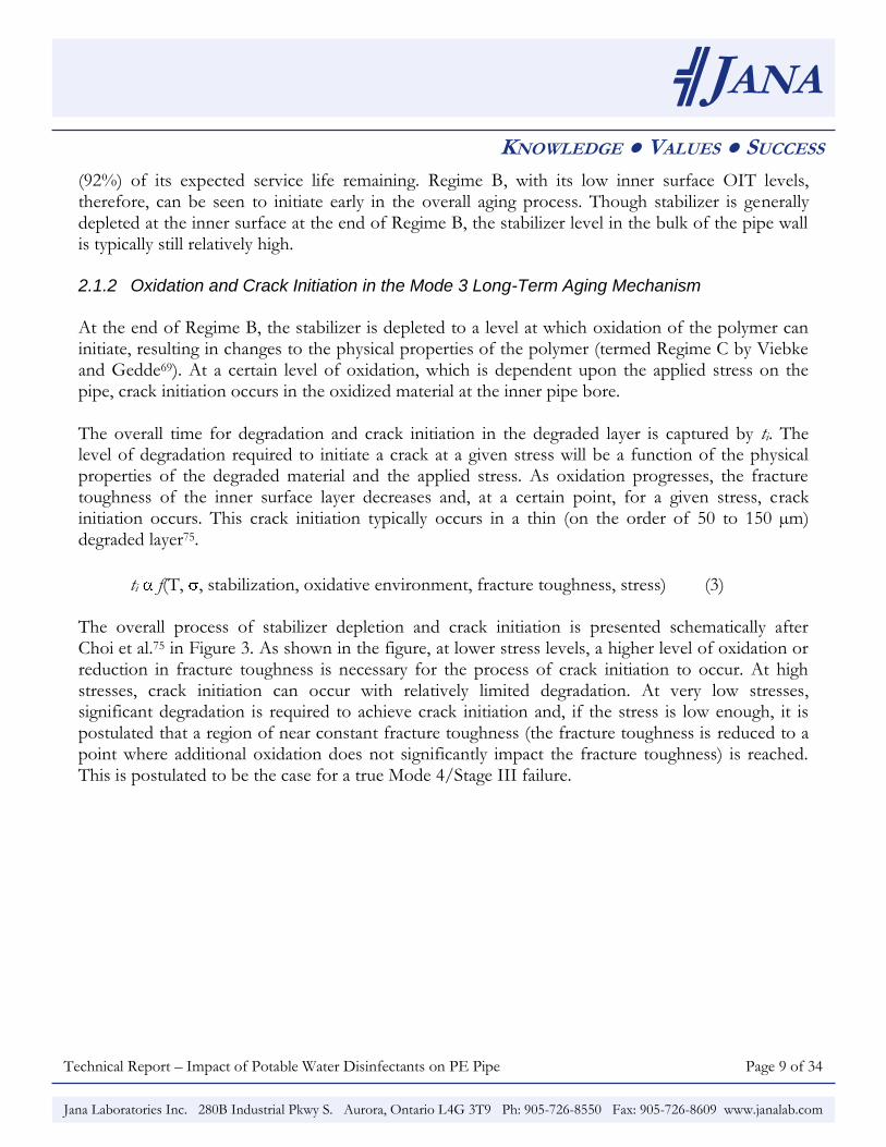
ti f(T, , stabilization, oxidative environment, fracture toughness, stress) (3) The overall process of stabilizer depletion and crack initiation is presented schematically after Choi et al.75 in Figure 3. As shown in the figure, at lower stress levels, a higher level of oxidation or reduction in fracture toughness is necessary for the process of crack initiation to occur. At high stresses, crack initiation can occur with relatively limited degradation. At very low stresses, significant degradation is required to achieve crack initiation and, if the stress is low enough, it is postulated that a region of near constant fracture toughness (the fracture toughness is reduced to a point where additional oxidation does not significantly impact the fracture toughness) is reached. This is postulated to be the case for a true Mode 4/Stage III failure.
Technical Report – Impact of Potable Water Disinfectants on PE Pipe Page 10 of 34
╣JANA
KNOWLEDGE ● VALUES ● SUCCESS
Jana Laboratories Inc. 280B Industrial Pkwy S. Aurora, Ontario L4G 3T9 Ph: 905-726-8550 Fax: 905-726-8609 www.janalab.com
Figure 3: Depiction of Crack Initiation Process in Mode 3 Aging Mechanism
2.1.3 Crack Propagation in the Mode 3 Long-Term Aging Mechanism
Once the crack is initiated, the crack propagates via a step-wise SCG mechanism. The time for crack propagation (tp) for a pure Mode 3 failure should be independent of the oxidative environment (as it is purely a mechanical process) and depends solely upon the temperature and stress as for a Stage II failure. It is postulated, though, that there is a continuum of shifting mechanisms between a pure Mode 3 and a pure Mode 4 failure through which the role of oxidation is shifting. That is, there is the potential for some level of degradation during crack propagation dependent upon the time scales of the competing mechanisms. As stress is lowered, the time scale for mechanical crack propagation increases and, at a certain point, the time scale for stabilizer depletion and oxidation of the micro-fibrils in the process zone becomes shorter than that for mechanical crack propagation and oxidation begins to play a role in crack propagation. Ultimately this leads to a shift from „Mode 3‟ to the Mode 4/Stage III aging mechanism.
tp f(T, , fracture toughness) (4)
Technical Report – Impact of Potable Water Disinfectants on PE Pipe Page 11 of 34
╣JANA
KNOWLEDGE ● VALUES ● SUCCESS
Jana Laboratories Inc. 280B Industrial Pkwy S. Aurora, Ontario L4G 3T9 Ph: 905-726-8550 Fax: 905-726-8609 www.janalab.com
2.1.4 Overall Mode 3 Long-Term Aging Mechanism
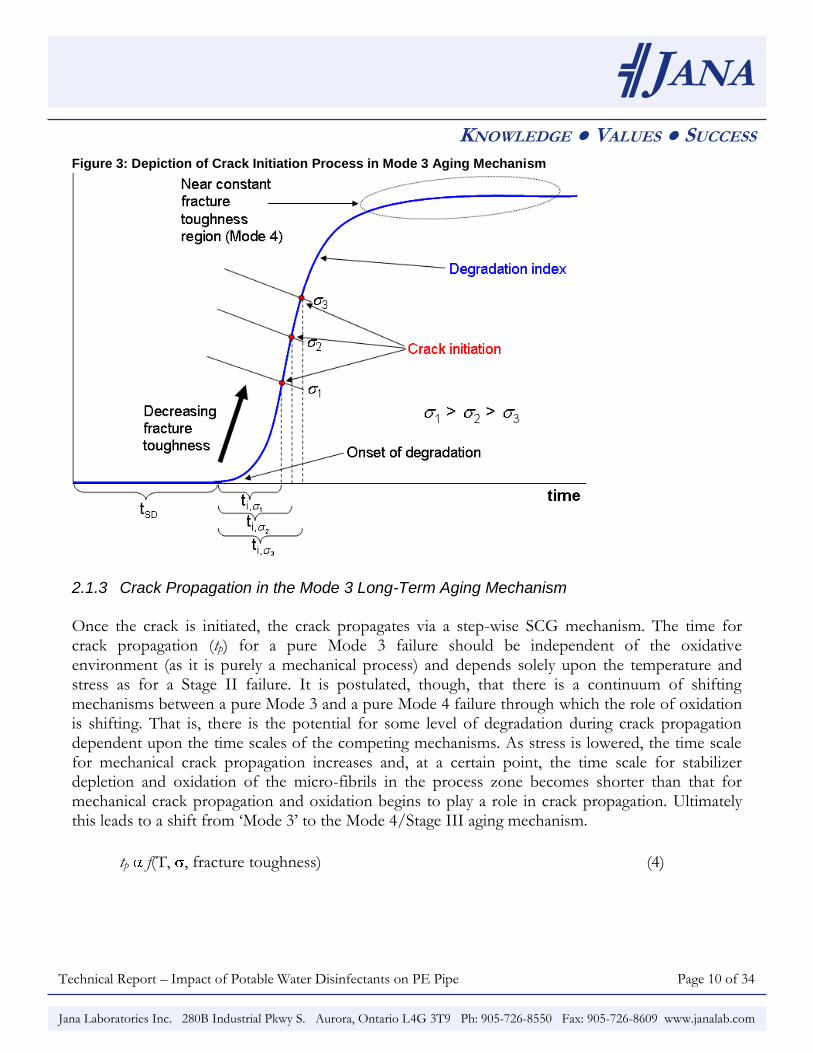
The overall process of Mode 3 aging is presented in Figure 4 based on data generated by the authors for a PE pipe material exposed to chlorinated potable water at elevated temperatures. Samples were removed throughout the exposure period and analyzed for stabilizer depletion (OIT analysis of inner exposed surface), evidence of oxidation (elevated carbonyl ratio), resistance of the inner surface to micro-cracking (bend-back), and micro-crack formation on the inner surface (Scanning Electron Microscopy (SEM)). The data are shown in dimensionless units for time and OIT (time over ultimate time to rupture (t/tf), OIT at time t over initial OIT). Similar data representations have been shown by Rozental et al.28. The Carbonyl Ratio introduced above is a relative measure of the level of oxidation of PE materials. The Carbonyl Ratio is defined by the ratio of integrated area of the carbonyl band defined by approximately 1800 cm-1 and 1660 cm-1 over the area defined by approximately 1480 cm-1 and 1440 cm-1. The values should be examined on a qualitative basis rather than comparing actual values because of interferences from contaminants and additives in the polymer. Higher Carbonyl Ratios generally indicate higher levels of oxidation. The Carbonyl Ratio is typically measured by performing micro Fourier Transform Infra-Red (FTIR) spectroscopy on surfaces or thin microtomed sections, and thus can be used to compare different small areas within a material or on a surface. The Carbonyl Ratio has been successfully used to characterize the aging process of PE piping materials3,24,38,40. In general, the Carbonyl Ratio increases in the early phase of the aging process, reaches a plateau and then levels off28,76. The onset of the initial increase in the Carbonyl Ratio and the plateau regions is dependent on the pipe formulation and the end-use environment. These onsets represent the onset of Regime C and the progression of the Regime C mechanism, respectively. The Regime C process is typically seen to overlap with the Regime B process and can extend for up to 80% of the overall pipe lifetime33.
Technical Report – Impact of Potable Water Disinfectants on PE Pipe Page 12 of 34
╣JANA
KNOWLEDGE ● VALUES ● SUCCESS
Jana Laboratories Inc. 280B Industrial Pkwy S. Aurora, Ontario L4G 3T9 Ph: 905-726-8550 Fax: 905-726-8609 www.janalab.com
As seen in Figure 4, for this material at the tested conditions, a rapid initial decrease in OIT at the inner surface is observed (Regime A) followed by Regime B where stabilizer is depleted at the inner surface. Initial degradation is observed at approximately 6% of the overall lifetime (based on carbonyl ratio and bend-back tests), and micro-cracking at the inner pipe surface under the action of the test stress is observed at approximately 13% of the overall test lifetime. Continued degradation is observed at the inner surface through to ultimate rupture of the pipe. The time for stabilizer depletion at the inner surface as measured by OIT relative to the overall lifetime is on the order of 5%, similar to the findings of Hoang and Lowe52. In testing of a range of materials at different conditions this value was observed to vary from roughly 5% to greater than 50% and is considered to be a function of the material, temperature, stress and oxidative environment. Given this wide spread, measurement of inner surface OIT is, therefore, not considered an effective means of assessing the remaining material lifetime. The reverse bend test, in which a strip of pipe is cut and bent back upon itself to expose the inner surface to high strain (much higher than would ever be observed in service) and examined for micro-cracking, was seen to show cracking on the inner surface prior to micro-cracks being observed on the undisturbed inner pipe surface. The relative time to observe cracking in reverse bend testing again varied significantly based on the material, temperature, stress and oxidative environment with no general correlation observed between cracking in the bend-back test and remaining test lifetime. While indicative of the onset of the first low levels of inner surface ductility
Technical Report – Impact of Potable Water Disinfectants on PE Pipe Page 13 of 34
╣JANA
KNOWLEDGE ● VALUES ● SUCCESS
Jana Laboratories Inc. 280B Industrial Pkwy S. Aurora, Ontario L4G 3T9 Ph: 905-726-8550 Fax: 905-726-8609 www.janalab.com
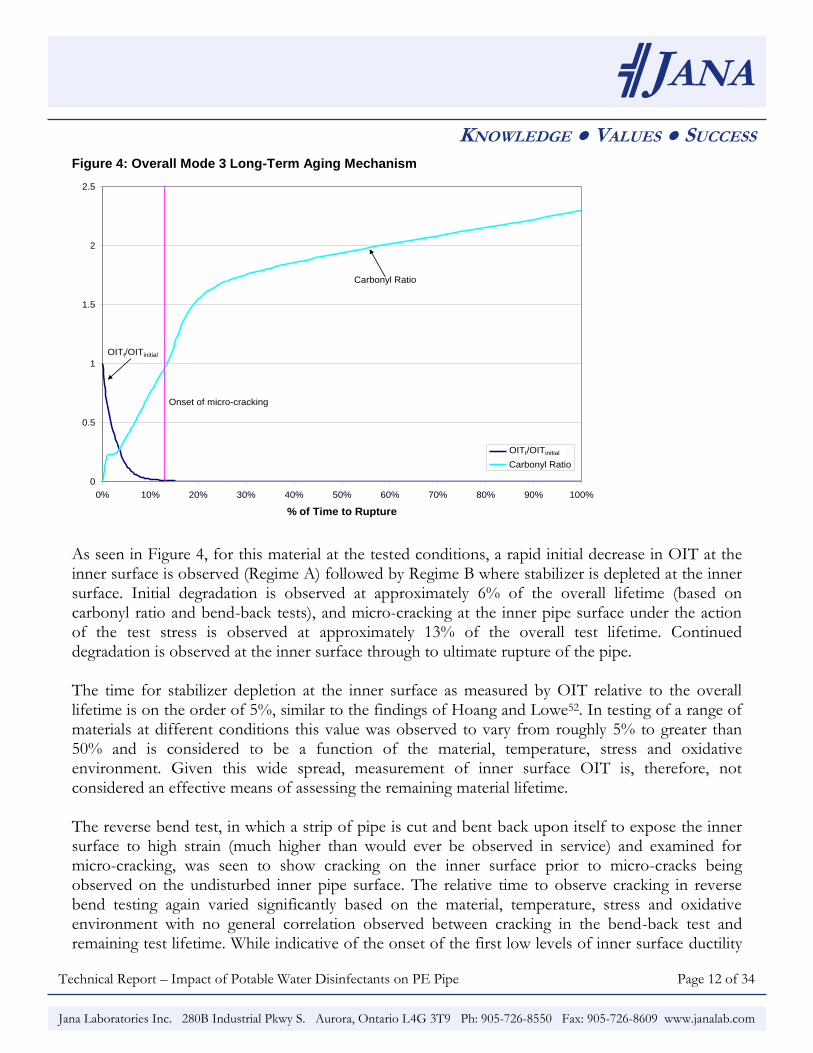
loss, the bend-back test does not provide a tool for projecting what portion of the overall performance lifetime the material is at. Figure 5 shows the micro-cracking observed for specimens at 13% and 26% of the overall time to rupture. Figure 5: Inner Surface After Bend-Back of Specimen at 13% and 26% of Overall Lifetime
(a) 13% of Overall Lifetime (b) 26% of Overall Lifetime
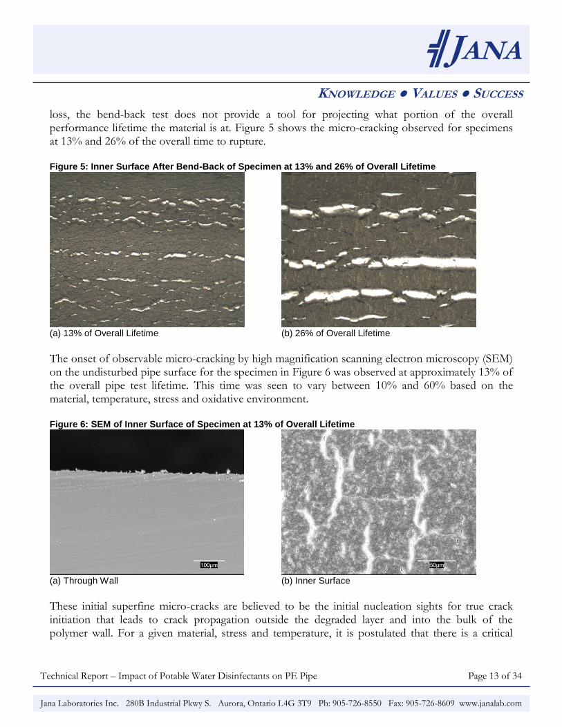
The onset of observable micro-cracking by high magnification scanning electron microscopy (SEM) on the undisturbed pipe surface for the specimen in Figure 6 was observed at approximately 13% of the overall pipe test lifetime. This time was seen to vary between 10% and 60% based on the material, temperature, stress and oxidative environment. Figure 6: SEM of Inner Surface of Specimen at 13% of Overall Lifetime
(a) Through Wall (b) Inner Surface
These initial superfine micro-cracks are believed to be the initial nucleation sights for true crack initiation that leads to crack propagation outside the degraded layer and into the bulk of the polymer wall. For a given material, stress and temperature, it is postulated that there is a critical
Technical Report – Impact of Potable Water Disinfectants on PE Pipe Page 14 of 34
╣JANA
KNOWLEDGE ● VALUES ● SUCCESS
Jana Laboratories Inc. 280B Industrial Pkwy S. Aurora, Ontario L4G 3T9 Ph: 905-726-8550 Fax: 905-726-8609 www.janalab.com
micro-crack size that must develop to initiate the mechanical SCG mechanism of a true Mode 3 failure. From the above, it is apparent that characterization of the inner pipe surface of exhumed from service piping by OIT, FTIR analysis (carbonyl ratio) or micro-cracking in bend-back testing does not and cannot provide an indication of the residual lifetime of a pipe sample. The inner surface depletion of OIT, the onset of an increase in the carbonyl ratio and micro-cracking in the bend back test, can all occur very early in the overall Mode 3 long-term aging mechanism and at different times for different materials and end-use conditions. As seen from the example above, these can all be observed with as much as 90% of the overall pipe lifetime remaining. Crack propagation in Stage II rupture is typically reported to comprise 10% to 50% of the overall time to rupture. Crack propagation (tp) in Mode 4 (Stage III) is seen to comprise as much as 90% of the overall time to rupture (tf). As crack initiation in Mode 3 is initiated through oxidation and crack propagation is occurring through largely mechanical means, the crack propagation time in Mode 3 is projected to lie between that observed for Mode I (Stage II) and Mode 4 (Stage III) with the value dependent upon the material, temperature, stress and oxidative environment. For the sample presented above, the transition from the crack initiation phase to the crack propagation phase is projected to occur at approximately 70% to 90% of the overall time to rupture. As discussed in a following section (Primary Product Factors Impact Long-Term Aging), the relative time for crack propagation to overall time to rupture is also projected to increase with increasing pipe wall thickness. Overall, therefore, the Mode 3 long-term aging mechanism is seen to be comprised of three primary regions, tsd, ti and tp, whose relative time scales are projected to vary with material and the operating conditions. The primary factors impacting the Mode 3 long-term aging mechanism are discussed in the two following sections. 3.0 Primary End-Use Factors Understanding the end-use environment and its impact on the Mode 3 long-term aging mechanism is critical to understanding how a material will perform in service. The three main parameters that impact the oxidative resistance of PE pipe in water distribution systems (aside from the product factors discussed in the next section) are:
Water Quality (oxidative aggressiveness)
Temperature
Pressure/Stress
Technical Report – Impact of Potable Water Disinfectants on PE Pipe Page 15 of 34
╣JANA
KNOWLEDGE ● VALUES ● SUCCESS
Jana Laboratories Inc. 280B Industrial Pkwy S. Aurora, Ontario L4G 3T9 Ph: 905-726-8550 Fax: 905-726-8609 www.janalab.com
As these operating parameters vary by utility, the performance of PE materials in the Mode 3 long-term aging mechanism is, therefore, very dependent on the end-use application (as is analogous performance of any pipe material). 3.1 Water Quality
The disinfectants added to potable water to maintain a residual through the distribution system are oxidants and, consequently, increase the oxidative aggressiveness of the water. A number of authors have examined the impact of disinfectant residuals on distribution system materials including crosslinked polyethylene (PEX), polybutylene (PB), polysulphone, copper, gasket materials and PE26,39,53-66. While wide variation in performance and susceptibility to oxidation is observed, in general, oxidation rates are seen to increase with an increase in the oxidative capabilities of the water. Characterization of the Mode 3 long-term aging mechanism (in which oxidation plays a role) must, therefore, take into account the end-use water qualities. It is important when considering the impact of these disinfectants to consider the disinfectants used for secondary treatment that provide a disinfectant residual in the distribution system and not those used for primary disinfection (which is typically consumed in the disinfection process and not active in the distribution system). The disinfectant residual used most often in North America is chlorine38. The other primary disinfectants commonly used include chloramines and, to a much lower extent (less than 1%)77, chlorine dioxide. Chlorinated water, even at low levels, results in a significantly increased oxidative potential of the water. As chlorine is the most common disinfectant and is seen to be more aggressive than chloramines, and because chlorine dioxide does not appear to be used as a secondary disinfectant for maintaining a residual in the distribution system in any significant way in the US25, validation testing for materials in potable water applications is typically focused on chlorine38,48,78. The characteristics of potable water in North American distribution systems vary greatly. The EPA guidelines for water entering the distribution system are for a pH range of 6.5 to 8.5 and a maximum chlorine concentration of 4 mg/L38 (ppm). The average values for water entering the distribution system are a pH of 7.7 and a chlorine concentration of 1.1 mg/L38. The pH of the water is reported to range from 6.1 to 10 and the chlorine concentration is reported as high as 4 mg/L. The combination of the pH and the chlorine concentration, along with other components in potable water (which interact to reduce the oxidative aggressiveness at a given pH and chlorine level)78, determine the overall oxidative strength of the water. Chlorine in water exists in equilibrium between hypochlorous acid (HOCl) and hypochlorite ions (OCl-):
Technical Report – Impact of Potable Water Disinfectants on PE Pipe Page 16 of 34
╣JANA
KNOWLEDGE ● VALUES ● SUCCESS
Jana Laboratories Inc. 280B Industrial Pkwy S. Aurora, Ontario L4G 3T9 Ph: 905-726-8550 Fax: 905-726-8609 www.janalab.com
The equilibrium is very sensitive to pH within the typical range found in potable water. At pH 6.5, the equilibrium is approximately 90% hypochlorous acid and at pH 8.5, only 10% hypochlorous acid. As hypochlorous acid is the much stronger oxidant, the equilibrium is expected to significantly affect the overall oxidative strength of the water. A measure of the overall oxidative strength of water is the oxidation-reduction potential (ORP) measured in millivolts (mV). The ORP is a relative measure of a solution's ability to oxidize and captures all oxidizers present in the water (i.e., it is not specific to chlorine). A higher ORP reading is generally indicative of water that will be more aggressive oxidatively. For reference, deionized water has an ORP in the range of 200 to 300 mV, while the recommended minimum level for maintaining swimming pool sanitation is 750 mV39. Deionized water with 0.5 mg/L chlorine has an ORP of approximately 550 mV at a pH of 8.5 and 800 mV at a pH of 6.548. The ORP of water generally decreases with increasing pH and increases with increasing chlorine concentration. ORP has been shown previously to correlate with long-term aging of piping materials in potable water applications38 with a linear relationship observed between log lifetime and ORP over a broad range of water qualities (from non-chlorinated water to water treated with 5 mg/L chlorine over a broad range of pH values). It is significant that the relationship between ORP and test lifetime holds over a wide range of chlorine concentrations and a range of pH values38. It is also significant that the relationship extends to non-chlorinated water38. Both of these observations, combined with similarities of the degradation and aging mechanisms over the range of water qualities examined, provide substantial support for the conclusion that the degradation of materials in chlorinated water is attributable not specifically to the chlorine content or chemistry but rather to the overall oxidative strength of the water. The ORP, therefore, appears to provide a means of comparing the impact of water quality on the Mode 3 aging mechanism across the full range of end-use operating conditions. An analysis of the chlorine and pH values reported by water utilities38 for water entering the distribution system predicts average ORP values of approximately 750 mV with values extending upwards to the low 800s. When the data are adjusted for chloramines and non-treated systems, it is projected that 50% of the US population receives water with an ORP below 650 mV and 80% with an ORP below 750 mV. To provide a sense of the impact of water quality on pipe performance, at a given end-use temperature and stress, the relative long-term aging with an ORP of 650 mV is projected to be occurring at rates of approximately 3 to 5 times slower than for an ORP of 750 mV. Given the broad range in end-use ORP values, therefore, long-term aging will vary significantly by utility. As detailed later in this paper, for high performing current generation PE materials, even at 750 mV this mechanism is projected to occur over many hundreds of years at average operating temperatures and generally only becomes of practical interest for design purposes at higher ORPs or temperatures.
Technical Report – Impact of Potable Water Disinfectants on PE Pipe Page 17 of 34
╣JANA
KNOWLEDGE ● VALUES ● SUCCESS
Jana Laboratories Inc. 280B Industrial Pkwy S. Aurora, Ontario L4G 3T9 Ph: 905-726-8550 Fax: 905-726-8609 www.janalab.com
3.2 Temperature
Oxidation is a thermally activated process as is crack initiation and propagation. It is no surprise, therefore, that the overall Mode 3 aging mechanism, comprised of oxidation, crack initiation and crack propagation, is seen to be a thermally activated process with the rate of “aging” increasing with increasing temperature. Temperature acceleration of the Mode 3 long-term aging mechanism (through acceleration of each of tsd, ti and tp) has been utilized in accelerated aging studies to examine the long term projected performance for this mechanism3,24,38,39,48 through accelerated testing and application of the Rate Process Method (RPM). The RPM projects a stress dependent effective activation energy with Arrhenius type temperature dependence according to Equations 7 and 879,
T
CB
A
f
et
log10ln
101
(7)
E = -R ln 10(B log – C) (8) where tf = time to failure (h), = hoop stress (MPa), T = temperature (K), R = gas constant, and A, B, and C = adjustable parameters. The effective activation energy represents the minimum energy required for a process to occur and reflects the observed temperature dependence. Higher effective activation energy reflects a greater increase in reaction rate with increasing temperature. In accelerated aging studies of PE in chlorinated potable water (Mode 3), the authors have observed activation energies for RPM modeling typically in the range of 65 to 90 kJ/mol. By comparison, activation energies for PE are typically in the range of 100 kJ/mol for oxidation, 85 to 120 kJ/mol for the Stage II SCG mechanism80,81, and 100 to 120 kJ/mol for Mode 4 failures. Viebke et al.79 report activation energies for the oxidative aging mechanism of PE in non-treated (non-chlorinated) water of 75 to 105 kJ/mol. The activation energies for Mode 3 are, therefore, in the same range, though generally lower than those for Stage II or Mode 4/Stage III. This is believed to be a consequence of the mechanisms of the Mode 3 long-term aging process as detailed in Figure 3 and the associated discussions presented previously. The crack initiation process, during which mechanical and oxidative processes are thought to be occurring at similar time scales, is thought to result in a catalytic effect that reduces the observed combined activation energy below those typically observed for oxidation and SCG independently.
Technical Report – Impact of Potable Water Disinfectants on PE Pipe Page 18 of 34
╣JANA
KNOWLEDGE ● VALUES ● SUCCESS
Jana Laboratories Inc. 280B Industrial Pkwy S. Aurora, Ontario L4G 3T9 Ph: 905-726-8550 Fax: 905-726-8609 www.janalab.com
Based on the AWWA Drinking Water Survey77, annual ground and surface water temperatures range from 3°C to 29°C, with an average around 15°C. The majority (80%) of water systems have average annual water temperatures below 20°C. To provide a sense of the impact of water temperature on pipe performance, at a given end-use water quality and stress, the relative aging rate at an average water temperature of 4°C is approximately 5 to 20 times slower than that at 20°C. Under typical water temperatures (20°C and lower), the Mode 3 long-term aging mechanism is occurring at relatively slow rates and good long-term performance would be expected. For those systems operating at the higher range of water temperatures, particularly when coupled with more aggressive water qualities, the system operating temperature could play a significant role in the accelerating Mode 3 aging mechanism. 3.3 Pressure/Stress
In general, the long-term aging mechanism of plastic piping materials is dependent on the applied stress as
tf -n (9) For the Stage I ductile mechanical process, n values in the range of 20 to 2782 are reported for PE materials and 25 for a PVC piping material83. Brown et al report n values in the range of 2.5 to 4.5 for Stage II mechanical SCG82. The authors have observed n values in the range of 0.4 to 1.1 for the Mode 4/Stage III aging mechanism. It is seen, therefore, that stress dependence decreases in moving from the Stage I to the Stage III aging mechanisms. This is also evident in Figure 2. For the Mode 3 long-term aging mechanism, n values between those of Stage II and Stage III are typically observed, showing a much lower stress dependence for Mode 3 than for the ductile-mechanical Stage I mechanism upon which pressure strength ratings are derived. According to the Handbook of Public Water Systems84, minimum acceptable water system pressures are typically between 35 to 40 psig and maximum pressures are 100 to 120 psig with average values around 70 psig. To provide a sense of the impact of stress on the Mode 3 aging mechanism, at a given water quality and ground water temperature, the relative Mode 3 aging rate at 35 psig is approximately 5 to 10 times slower than that at 80 psig internal pressure. 3.4 Overall Impact of Primary Variables
Combined, the three primary variables of water quality, temperature and operating pressure/stress determine the overall aging rate in Mode 3. The majority of end-use applications would be expected
Technical Report – Impact of Potable Water Disinfectants on PE Pipe Page 19 of 34
╣JANA
KNOWLEDGE ● VALUES ● SUCCESS
Jana Laboratories Inc. 280B Industrial Pkwy S. Aurora, Ontario L4G 3T9 Ph: 905-726-8550 Fax: 905-726-8609 www.janalab.com
to center around the average operating conditions for the three variables. There is the potential, however, for specific applications to create environments that are considerably more aggressive than those for typical applications. As with other piping materials, such as copper7, ductile iron and concrete, regional or utility differences in performance could be observed based on the operating conditions. Considering the methodologies detailed in a following section, the PE industry is actively working to develop application specific guidance for those limited instances where the primary variables combine to produce extremely aggressive environments. These are areas where high water temperatures combine with the most aggressive water qualities at the highest stresses in smaller diameter tubing. 4.0 Primary Product Factors There are three primary product factors that impact the performance of a PE pipe relative to the Mode 3 long-term aging mechanism:
Stabilizer System
Base Resin
Pipe Size These three factors, combined with the three primary end-use factors, determine the overall rate of the Mode 3 long-term aging mechanism. 4.1 Stabilizer System As discussed previously, the time for stabilizer depletion, tsd, is one of three key factors in the overall Mode 3 long-term aging mechanism. This time is, in addition to the water quality and temperature, controlled by the stabilizer/resin system. As such, the stabilizer system utilized for a piping material will impact the overall Mode 3 mechanism. For PE piping materials, considerable research has been conducted towards the development of stabilizer systems for long-term performance35,36,69-72,85-90. This has led to the use of sophisticated stabilization systems to protect the pipe material during manufacturing and in the end-use application. Proper selection of the stabilization system has been demonstrated to provide significant advances in the overall Mode 3 long-term aging mechanism.
4.2 Base Resin Properties The base resin in a PE pipe formulation is highly engineered to provide the balance of properties required by the end-use application and, overall, there has been considerable evolution in the
Technical Report – Impact of Potable Water Disinfectants on PE Pipe Page 20 of 34
╣JANA
KNOWLEDGE ● VALUES ● SUCCESS
Jana Laboratories Inc. 280B Industrial Pkwy S. Aurora, Ontario L4G 3T9 Ph: 905-726-8550 Fax: 905-726-8609 www.janalab.com
performance properties of these materials since the earliest PE resin introduced to the potable water market52. Considerable research has been conducted to connect the molecular structure of PE materials with both Stage I80,91,92 and Stage II80,81,91-97 performance, as well as other mechanical properties like Rapid Crack Propagation (RCP)96-99. Polyethylene is now specifically tailored in terms of the molecular architecture to improve long-term performance in piping applications. The impact of the molecular level structure on the Mode 3 long-term aging mechanism has not been as well characterized and is an area of current research. In general, factors that increase ti and/or tp are expected to improve overall performance. Given the high base level performance of current PE resins, initial research indicates that the improvement of the stabilizer system has a larger impact on further improvement to the overall Mode 3 aging mechanism. 4.3 Pipe Size (Scale Effects)
Based on an analysis of the available experimental data and an examination of the Mode 3 long-term aging mechanism, long-term performance is projected to increase with increasing pipe size; that is, the Mode 3 aging mechanism will take longer to occur in, say, a 4" pipe than a ¾" pipe and longer still in a 12" pipe when operated at the same internal pressure (i.e., consistent wall stress). As discussed previously, the overall time to rupture (tf) for the Mode 3 aging mechanism is represented by:
tf = tsd + ti + tp (1) where tsd is the time for stabilizer depletion, ti the time for crack initiation and tp the time for crack propagation. Both tsd and ti are projected to be relatively independent of pipe diameter within a given dimension ratio (DR) series, as they are occurring in a thin region at the inner pipe surface (50 to 150 µm)33 where, in a given application, the water quality, temperature and stress will be constant. For tp, however, which proceeds through a stepwise slow crack growth mechanism through the pipe wall, the time for crack propagation at the same temperature and stress conditions will depend on the distance the crack has to traverse and, consequently, on the wall thickness of pipe diameter for a given DR series. Consequently, the overall Mode 3 long-term aging mechanism will take longer in a larger diameter pipe. Much of the early PE pipe installations were for smaller diameter service lines. The performance of larger diameter PE mains, the installation of which has gained in popularity in the US through the last decade, would be expected to exceed the performance observed for these smaller diameter service line materials. The current ASTM F2263 test methodology (discussed in a following section) for assessing the Mode 3 long-term aging mechanism is based on testing of ½″ diameter tubing with a 0.090″ wall
Technical Report – Impact of Potable Water Disinfectants on PE Pipe Page 21 of 34
╣JANA
KNOWLEDGE ● VALUES ● SUCCESS
Jana Laboratories Inc. 280B Industrial Pkwy S. Aurora, Ontario L4G 3T9 Ph: 905-726-8550 Fax: 905-726-8609 www.janalab.com
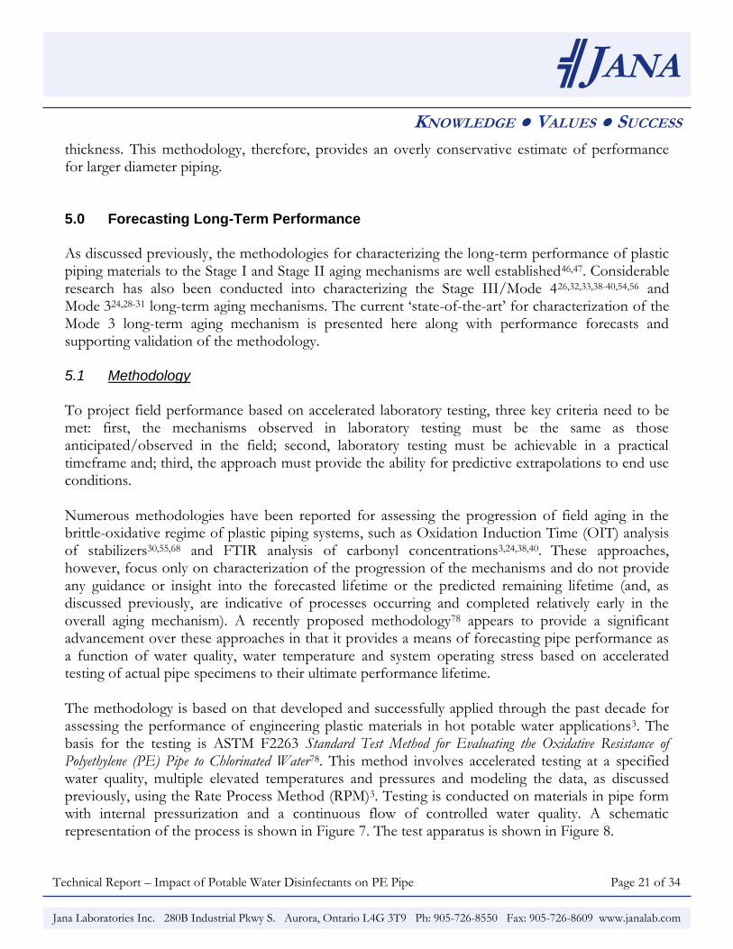
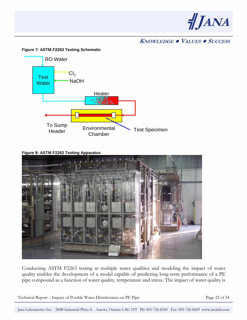
thickness. This methodology, therefore, provides an overly conservative estimate of performance for larger diameter piping. 5.0 Forecasting Long-Term Performance As discussed previously, the methodologies for characterizing the long-term performance of plastic piping materials to the Stage I and Stage II aging mechanisms are well established46,47. Considerable research has also been conducted into characterizing the Stage III/Mode 426,32,33,38-40,54,56 and Mode 324,28-31 long-term aging mechanisms. The current „state-of-the-art‟ for characterization of the Mode 3 long-term aging mechanism is presented here along with performance forecasts and supporting validation of the methodology. 5.1 Methodology To project field performance based on accelerated laboratory testing, three key criteria need to be met: first, the mechanisms observed in laboratory testing must be the same as those anticipated/observed in the field; second, laboratory testing must be achievable in a practical timeframe and; third, the approach must provide the ability for predictive extrapolations to end use conditions. Numerous methodologies have been reported for assessing the progression of field aging in the brittle-oxidative regime of plastic piping systems, such as Oxidation Induction Time (OIT) analysis of stabilizers30,55,68 and FTIR analysis of carbonyl concentrations3,24,38,40. These approaches, however, focus only on characterization of the progression of the mechanisms and do not provide any guidance or insight into the forecasted lifetime or the predicted remaining lifetime (and, as discussed previously, are indicative of processes occurring and completed relatively early in the overall aging mechanism). A recently proposed methodology78 appears to provide a significant advancement over these approaches in that it provides a means of forecasting pipe performance as a function of water quality, water temperature and system operating stress based on accelerated testing of actual pipe specimens to their ultimate performance lifetime. The methodology is based on that developed and successfully applied through the past decade for assessing the performance of engineering plastic materials in hot potable water applications3. The basis for the testing is ASTM F2263 Standard Test Method for Evaluating the Oxidative Resistance of Polyethylene (PE) Pipe to Chlorinated Water78. This method involves accelerated testing at a specified water quality, multiple elevated temperatures and pressures and modeling the data, as discussed previously, using the Rate Process Method (RPM)3. Testing is conducted on materials in pipe form with internal pressurization and a continuous flow of controlled water quality. A schematic representation of the process is shown in Figure 7. The test apparatus is shown in Figure 8.
Technical Report – Impact of Potable Water Disinfectants on PE Pipe Page 22 of 34
╣JANA
KNOWLEDGE ● VALUES ● SUCCESS
Jana Laboratories Inc. 280B Industrial Pkwy S. Aurora, Ontario L4G 3T9 Ph: 905-726-8550 Fax: 905-726-8609 www.janalab.com
Figure 7: ASTM F2263 Testing Schematic
Test
Water
RO Water
CI2
NaOH
Heater
To Sump
HeaderEnvironmental
ChamberTest Specimen
Test
Water
RO Water
CI2
NaOH
Heater
To Sump
HeaderEnvironmental
ChamberTest Specimen
Figure 8: ASTM F2263 Testing Apparatus
Conducting ASTM F2263 testing at multiple water qualities and modeling the impact of water quality enables the development of a model capable of predicting long-term performance of a PE pipe compound as a function of water quality, temperature and stress. The impact of water quality is
Technical Report – Impact of Potable Water Disinfectants on PE Pipe Page 23 of 34
╣JANA
KNOWLEDGE ● VALUES ● SUCCESS
Jana Laboratories Inc. 280B Industrial Pkwy S. Aurora, Ontario L4G 3T9 Ph: 905-726-8550 Fax: 905-726-8609 www.janalab.com
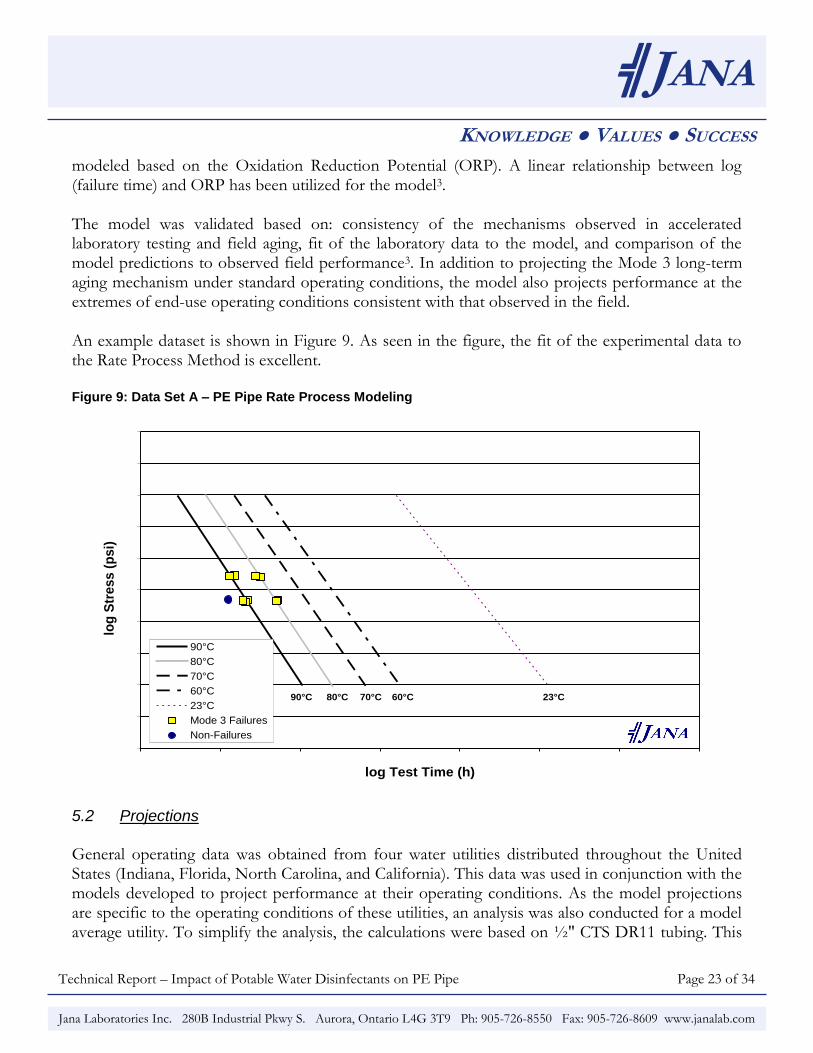
modeled based on the Oxidation Reduction Potential (ORP). A linear relationship between log (failure time) and ORP has been utilized for the model3. The model was validated based on: consistency of the mechanisms observed in accelerated laboratory testing and field aging, fit of the laboratory data to the model, and comparison of the model predictions to observed field performance3. In addition to projecting the Mode 3 long-term aging mechanism under standard operating conditions, the model also projects performance at the extremes of end-use operating conditions consistent with that observed in the field. An example dataset is shown in Figure 9. As seen in the figure, the fit of the experimental data to the Rate Process Method is excellent. Figure 9: Data Set A – PE Pipe Rate Process Modeling
2.00
2.10
2.20
2.30
2.40
2.50
2.60
2.70
2.80
2.90
3.00
2.00 3.00 4.00 5.00 6.00 7.00 8.00 9.00log Test Time (h)
log
Str
es
s (
ps
i)
90°C
80°C
70°C
60°C
23°C
Mode 3 Failures
Non-Failures JANA
23°C60°C70°C80°C90°C
5.2 Projections General operating data was obtained from four water utilities distributed throughout the United States (Indiana, Florida, North Carolina, and California). This data was used in conjunction with the models developed to project performance at their operating conditions. As the model projections are specific to the operating conditions of these utilities, an analysis was also conducted for a model average utility. To simplify the analysis, the calculations were based on ½" CTS DR11 tubing. This
Technical Report – Impact of Potable Water Disinfectants on PE Pipe Page 24 of 34
╣JANA
KNOWLEDGE ● VALUES ● SUCCESS
Jana Laboratories Inc. 280B Industrial Pkwy S. Aurora, Ontario L4G 3T9 Ph: 905-726-8550 Fax: 905-726-8609 www.janalab.com
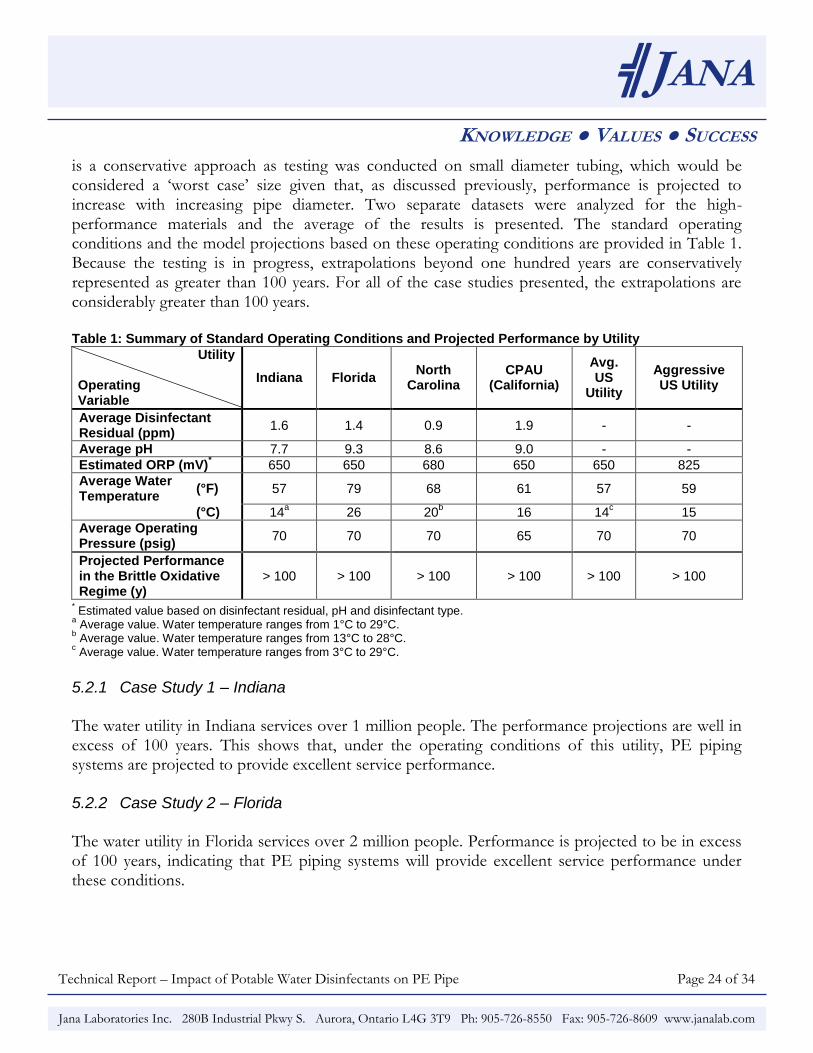
is a conservative approach as testing was conducted on small diameter tubing, which would be considered a „worst case‟ size given that, as discussed previously, performance is projected to increase with increasing pipe diameter. Two separate datasets were analyzed for the high-performance materials and the average of the results is presented. The standard operating conditions and the model projections based on these operating conditions are provided in Table 1. Because the testing is in progress, extrapolations beyond one hundred years are conservatively represented as greater than 100 years. For all of the case studies presented, the extrapolations are considerably greater than 100 years. Table 1: Summary of Standard Operating Conditions and Projected Performance by Utility
Utility Operating Variable
Indiana Florida North
Carolina CPAU
(California)
Avg. US
Utility
Aggressive US Utility
Average Disinfectant Residual (ppm)
1.6 1.4 0.9 1.9 - -
Average pH 7.7 9.3 8.6 9.0 - -
Estimated ORP (mV)* 650 650 680 650 650 825
Average Water Temperature
(°F) 57 79 68 61 57 59
(°C) 14a 26 20
b 16 14
c 15
Average Operating Pressure (psig)
70 70 70 65 70 70
Projected Performance in the Brittle Oxidative Regime (y)
> 100 > 100 > 100 > 100 > 100 > 100
* Estimated value based on disinfectant residual, pH and disinfectant type.
a Average value. Water temperature ranges from 1°C to 29°C.
b Average value. Water temperature ranges from 13°C to 28°C.
c Average value. Water temperature ranges from 3°C to 29°C.
5.2.1 Case Study 1 – Indiana
The water utility in Indiana services over 1 million people. The performance projections are well in excess of 100 years. This shows that, under the operating conditions of this utility, PE piping systems are projected to provide excellent service performance. 5.2.2 Case Study 2 – Florida The water utility in Florida services over 2 million people. Performance is projected to be in excess of 100 years, indicating that PE piping systems will provide excellent service performance under these conditions.
Technical Report – Impact of Potable Water Disinfectants on PE Pipe Page 25 of 34
╣JANA
KNOWLEDGE ● VALUES ● SUCCESS
Jana Laboratories Inc. 280B Industrial Pkwy S. Aurora, Ontario L4G 3T9 Ph: 905-726-8550 Fax: 905-726-8609 www.janalab.com
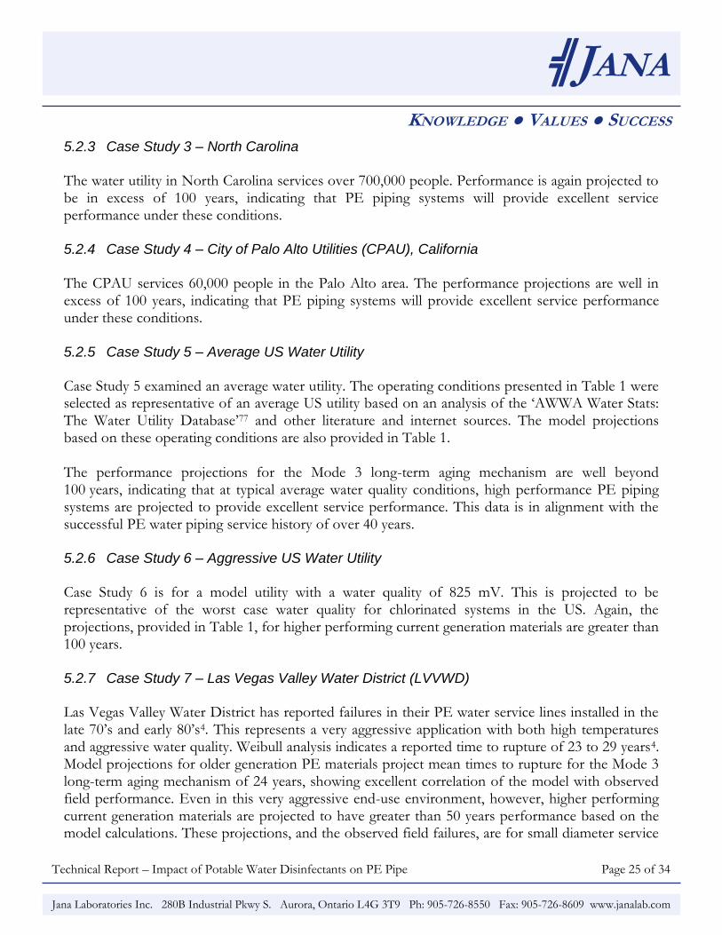
5.2.3 Case Study 3 – North Carolina
The water utility in North Carolina services over 700,000 people. Performance is again projected to be in excess of 100 years, indicating that PE piping systems will provide excellent service performance under these conditions. 5.2.4 Case Study 4 – City of Palo Alto Utilities (CPAU), California
The CPAU services 60,000 people in the Palo Alto area. The performance projections are well in excess of 100 years, indicating that PE piping systems will provide excellent service performance under these conditions. 5.2.5 Case Study 5 – Average US Water Utility
Case Study 5 examined an average water utility. The operating conditions presented in Table 1 were selected as representative of an average US utility based on an analysis of the „AWWA Water Stats: The Water Utility Database‟77 and other literature and internet sources. The model projections based on these operating conditions are also provided in Table 1. The performance projections for the Mode 3 long-term aging mechanism are well beyond 100 years, indicating that at typical average water quality conditions, high performance PE piping systems are projected to provide excellent service performance. This data is in alignment with the successful PE water piping service history of over 40 years. 5.2.6 Case Study 6 – Aggressive US Water Utility
Case Study 6 is for a model utility with a water quality of 825 mV. This is projected to be representative of the worst case water quality for chlorinated systems in the US. Again, the projections, provided in Table 1, for higher performing current generation materials are greater than 100 years. 5.2.7 Case Study 7 – Las Vegas Valley Water District (LVVWD) Las Vegas Valley Water District has reported failures in their PE water service lines installed in the late 70‟s and early 80‟s4. This represents a very aggressive application with both high temperatures and aggressive water quality. Weibull analysis indicates a reported time to rupture of 23 to 29 years4. Model projections for older generation PE materials project mean times to rupture for the Mode 3 long-term aging mechanism of 24 years, showing excellent correlation of the model with observed field performance. Even in this very aggressive end-use environment, however, higher performing current generation materials are projected to have greater than 50 years performance based on the model calculations. These projections, and the observed field failures, are for small diameter service
Technical Report – Impact of Potable Water Disinfectants on PE Pipe Page 26 of 34
╣JANA
KNOWLEDGE ● VALUES ● SUCCESS
Jana Laboratories Inc. 280B Industrial Pkwy S. Aurora, Ontario L4G 3T9 Ph: 905-726-8550 Fax: 905-726-8609 www.janalab.com
tubing. As discussed previously, larger diameter piping would be projected to have even better performance. In general, therefore, higher performing current generation PE piping materials are projected to have excellent longevity in the majority of potable water applications. At the extremes of the end-use operating window, however, where aggressive water qualities are combined with high water temperatures, more careful consideration should be directed to system design to ensure that PE materials are properly applied. 6.0 Summary Polyethylene piping materials have been used in potable water applications for over 50 years with considerable success. Through this time the material characteristics have evolved significantly along with the understanding of the long-term aging mechanisms for these materials. Currently the long-term aging mechanisms are well characterized and standard performance characterization and design approaches have been developed and standardized for the Stage I and Stage II aging mechanisms. More recently a methodology has been developed for characterization of the Mode 3 long-term aging mechanism. This methodology for forecasting long-term aging for this mechanism shows that performance is a function of the water quality, water temperature and operating stress and varies by utility. The model provides projections in line with observed field performance of older generation service tubing, both for the majority of applications where PE pipe have successfully been used and for the limited instances of very aggressive end-use applications where performance has not been as expected. Overall, the methodology developed to project PE pipe performance shows that higher performing current generation materials are expected to have excellent longevity across the majority of end-use applications and good performance even in very aggressive end-use environments. The model is also able to characterize performance for older installed PE piping materials and provide projections in line with observed field performance providing a tool for understanding and characterizing those limited instances where performance has not been as expected. Currently, the model is being refined and finalized, and methodologies for its utilization in providing design guidance are being developed.
Technical Report – Impact of Potable Water Disinfectants on PE Pipe Page 27 of 34
╣JANA
KNOWLEDGE ● VALUES ● SUCCESS
Jana Laboratories Inc. 280B Industrial Pkwy S. Aurora, Ontario L4G 3T9 Ph: 905-726-8550 Fax: 905-726-8609 www.janalab.com
7.0 References 1. R. E. Chambers, Performance of Polyolefin Plastic Pipe and Tubing in the Water Service Application.
1984, Simpson Gumpertz & Heger Inc.: Arlington, MA. p. 154.
2. C. Thompson and D. Jenkins, Review of Water Industry Plastic Pipe Practices. 1987, University of California: Berkeley, CA. p. 85.
3. P. Vibien et al., Long-Term Performance of Polyethylene Piping Materials in Potable Water Applications. 2009, Jana Laboratories, Inc.: Aurora, ON. p. 10.
4. C. W. Scott, Forecasting Pipe Replacements Using Weibull Analysis, in Society for Maintenance & Reliability Engineers Annual Conference. p. 8.
5. D. M. Bastidas et al., Copper Deterioration: Causes, Diagnosis and Risk Minimisation. International Materials Reviews, 2010. 55(2): p. 99-127.
6. O. E. Farooqi et al., Copper Pinhole Failures: Plumbing Susceptibility and Management. Journal of Water Resources Planning and Management-ASCE, 2009. 135(4): p. 227-236.
7. E. J. Kleczyk and D. J. Bosch, Incidence and Costs of Home Plumbing Corrosion. Journal of the American Water Works Association, 2008. 100(12): p. 122-133.
8. A. E. Cantor et al., Copper Pipe Failure by Microbiologically Influenced Corrosion. Materials Performance, 2006. 45(6): p. 38-41.
9. G. V. Loganathan and J. Lee, Decision Tool for Optimal Replacement of Plumbing Systems. Civil Engineering and Environmental Systems, 2005. 22(4): p. 189-204.
10. C. W. Keevil, The Physico-Chemistry of Biofilm-Mediated Pitting Corrosion of Copper Pipe Supplying Potable Water. Water Science and Technology, 2004. 49(2): p. 91-98.
11. K. Nielsen, Metallic Materials in Danish Supply Water Systems, in Pipe Material Selection in Drinking Water Systems, B. Berghult, A.E. Broo, and T. Hedberg, Editors. 2001, IWA Publishing: London. p. 83-90.
12. P. J. Bremer, B. J. Webster, and D. B. Wells, Biocorrosion of Copper in Potable Water. Journal of the American Water Works Association, 2001. 93(8): p. 82-91.
13. I. Hussain, S. H. Hamid, and J. H. Khan, Polyvinyl-Chloride Pipe Degradation Studies in Natural Environments. Journal of Vinyl & Additive Technology, 1995. 1(3): p. 137-141.
Technical Report – Impact of Potable Water Disinfectants on PE Pipe Page 28 of 34
╣JANA
KNOWLEDGE ● VALUES ● SUCCESS
Jana Laboratories Inc. 280B Industrial Pkwy S. Aurora, Ontario L4G 3T9 Ph: 905-726-8550 Fax: 905-726-8609 www.janalab.com
14. P. Davis et al., A Physical Probabilistic Model to Predict Failure Rates in Buried PVC Pipelines. Reliability Engineering & System Safety, 2007. 92(9): p. 1258-1266.
15. G. P. Marshall, S. Brogden, and M. A. Shepherd, Evaluation of Surge and Fatigue Resistance of Poly(vinyl chloride) and Polyethylene Pipeline Materials for Use in the UK Water Industry. Plastics Rubber and Composites Processing and Applications, 1998. 27(10): p. 483-488.
16. Peel Regional Council, Material Specifications for Large Diameter Water Mains. 2005: Region of Peel. p. 22.
17. J. Schramuk and V. Rash, Cathodic Protection for a New Ductile Iron Water Transmission Main. Materials Performance, 2005. 44(10): p. 20-24.
18. M. V. Seica et al., Evaluation of Properties of Toronto Iron Water Mains and Surrounding Soil. Canadian Journal of Civil Engineering, 2002. 29(2): p. 222-237.
19. J. H. Lei and S. Saegrov, Statistical Approach for Describing Failures and Lifetimes of Water Mains. Water Science and Technology, 1998. 38(6): p. 209-217.
20. A. Valiente, Stress Corrosion Failure of Large Diameter Pressure Pipelines of Prestressed Concrete. Engineering Failure Analysis, 2001. 8(3): p. 245-261.
21. D. H. Marshall and W. Worthington, Increasing the Reliability of Concrete Pressure Pipe. Trenchless Pipeline Projects - Practical Applications, ed. L.E. Osborn. 1997, New York: American Society of Civil Engineers. 273-282.
22. D. E. Duvall and D. B. Edwards, Oxidative Degradation of High Density Polyethylene Pipes from Exposure to Drinking Water Disinfectants. 2009, Engineering Systems Inc.: Aurora, IL. p. 75.
23. T. Kosari and S. Chung, Preliminary Examination of the Impact of Pipe Wall Thickness on Chlorine Resistance of PE Tubing. 2010, Jana Laboratories, Inc.: Aurora, ON. p. 19.
24. S. Chung et al., Modelling Mechanisms of Brittle Oxidative Degradation to Ensure Plastic Pipe Material Performance, in ANTEC. 2004. p. 5.
25. S. Lee and S. Chung, Chlorine Dioxide Usage in North America. 2010, Jana Laboratories, Inc.: Aurora, ON. p. 30.
26. P. Vibien et al., Assessing Material Performance in Chlorinated Potable Water Applications, in Plastics Pipes XI. 2001. p. 8.
27. J. P. Dear and N. S. Mason, The Effects of Chlorine Depletion of Antioxidants in Polyethylene. Polymers & Polymer Composites, 2001. 9(1): p. 1-13.
Technical Report – Impact of Potable Water Disinfectants on PE Pipe Page 29 of 34
╣JANA
KNOWLEDGE ● VALUES ● SUCCESS
Jana Laboratories Inc. 280B Industrial Pkwy S. Aurora, Ontario L4G 3T9 Ph: 905-726-8550 Fax: 905-726-8609 www.janalab.com
28. M. Rozental-Evesque et al., The Polyethylene Life Cycle, in ASTEE. 2009. p. 13.
29. B. Rabaud and M. Rozental-Evesque, Interactions Between Polyethylene Water Pipes and Disinfectants Used in Water Treatments by Means of a Field Study and a Bench Scale Testing Program. p. 9.
30. X. Colin et al., Kinetic Modeling of the Aging of Polyethylene Pipes for the Transport of Water Containing Disinfectants, in Plastics Pipes XIII. 2006: Washington, DC.
31. X. Colin, L. Audouin, and J. Verdu, Towards a Non Empirical Kinetic Model for the Lifetime Prediction of Polyethylene Pipes Transporting Drinking Water. Macromolecular Symposia, 2009. 286: p. 81-88.
32. M. Ifwarson and K. Aoyama, Results and Experiences from Tests on Polyolefin Pipes Exposed to Chlorinated Water. p. 12.
33. U. W. Gedde et al., Long-Term Properties of Hot-Water Polyolefin Pipes - A Review. Polymer Engineering and Science, 1994. 34(24): p. 1773-1787.
34. M. Ifwarson, Life-Time of Polyethylene Pipes Under Pressure and Exposure to High Temperatures. Kunstoffe German Plastics, 1989. 79(6): p. 525-529.
35. G. Dorner and R. W. Lang, Influence of Various Stabilizer Systems on the Ageing Behavior of PE-MD - I. Hot-Water Ageing of Compression Molded Plaques. Polymer Degradation and Stability, 1998. 62(3): p. 421-430.
36. G. Dorner and R. W. Lang, Influence of Various Stabilizer Systems on the Ageing Behavior of PE-MD - II. Ageing of Pipe Specimens in Air and Water at Elevated Temperatures. Polymer Degradation and Stability, 1998. 62(3): p. 431-440.
37. Y. Ohtake et al., Oxidative Degradation and Molecular Weight Change of LDPE Buried Under Bioactive Soil for 32-37 Years. Journal of Applied Polymer Science, 1998. 70(9): p. 1643-1648.
38. S. Chung et al., Environmental Factors in Performance Forecasting of Plastic Piping Materials, in ANTEC. 2003. p. 5.
39. P. Vibien et al., Chlorine Resistance Testing of Cross-Linked Polyethylene Piping Materials, in ANTEC. 2001. p. 5.
40. S. Chung et al., Characterizing Long-Term Performance of Plastic Piping Materials in Potable Water Applications, in Plastics Pipes XIV. 2008. p. 10.
Technical Report – Impact of Potable Water Disinfectants on PE Pipe Page 30 of 34
╣JANA
KNOWLEDGE ● VALUES ● SUCCESS
Jana Laboratories Inc. 280B Industrial Pkwy S. Aurora, Ontario L4G 3T9 Ph: 905-726-8550 Fax: 905-726-8609 www.janalab.com
41. S. Chung et al., An Examination of Field Failures of Plastic Piping System Components in Potable Water Applications, in ANTEC. 2007. p. 5.
42. S. A. Mruk, Thermoplastics Piping: A Review, in Managing Corrosion with Plastics. 1979, National Association of Corrosion Engineers: Houston, TX.
43. Plastics Pipe Institute, The Plastic Pipe Institute Handbook of Polyethylene Pipe. 1st ed. 2006, Washington, DC. 542.
44. TN-16 Rate Process Method for Projecting Performance of Polyethylene Piping Components, Plastics Pipe Institute, 2008.
45. TN-7 Nature of Hydrostatic Stress Rupture Curves, Plastics Pipe Institute, 2005.
46. D2837 Standard Test Method for Obtaining Hydrostatic Design Basis for Thermoplastic Materials or Pressure Design Basis for Thermoplastic Pipe Products, ASTM International, West Conshohocken, PA, 2008.
47. F1473 Standard Test Method for Notch Tensile Test to Measure the Resistance to Slow Crack Growth of Polyethylene Pipes and Resins, ASTM International, West Conshohocken, PA, 2007.
48. F2023 Standard Test Method for Evaluating the Oxidative Resistance of Crosslinked Polyethylene (PEX) Tubing and Systems to Hot Chlorinated Water, ASTM International, West Conshohocken, PA, 2009.
49. TR-4 PPI Listing of Hydrostatic Design Basis (HDB), Hydrostatic Design Stress (HDS), Strength Design Basis (SDB), Pressure Design Basis (PDB) and Minimum Required Strength (MRS) Ratings for Thermoplastic Piping Materials or Pipe, Plastics Pipe Institute, Irving, TX, 2009.
50. U. Schulte, A Vision Becomes True - 50 Years of Pipes Made From High Density Polyethylene, in Plastics Pipes XIII. 2006: Washington, DC. p. 10.
51. TR-3 Policies and Procedures for Developing Hydrostatic Design Basis (HDB), Hydrostatic Design Stress (HDS), Pressure Design Basis (PDB), Strength Design Basis (SDB), and Minimum Required Strength (MRS) Ratings for Thermoplastic Materials or Pipe, Plastics Pipe Institute, Irving, TX, 2008.
52. TN-41 High Performance PE Materials for Water Piping Applications, Plastics Pipe Institute, Irving, TX, 2007.
53. S. Chung et al., An Examination of the Relative Impact of Common Potable Water Disinfectants (Chlorine, Chloramines and Chlorine Dioxide) on Plastic Piping System Components, in Plastics Pipes XIII. 2006. p. 5.
Technical Report – Impact of Potable Water Disinfectants on PE Pipe Page 31 of 34
╣JANA
KNOWLEDGE ● VALUES ● SUCCESS
Jana Laboratories Inc. 280B Industrial Pkwy S. Aurora, Ontario L4G 3T9 Ph: 905-726-8550 Fax: 905-726-8609 www.janalab.com
54. T. S. Gill et al., Long Term Durability of Crosslinked Polyethylene Tubing Used in Chlorinated Hot Water Systems. Plastics, Rubber and Composites, 1999. 23(6): p. 309-313.
55. A. Tanaka, S. Akiyama, and S. Komukai, Influence of Residual Chlorine on Durability Cross-linked Polyethylene and Polybutene Pipes used in Hot-Water Supply Systems. p. 567-572.
56. U. W. Gedde and M. Ifwarson, Molecular-Structure and Morphology of Crosslinked Polyethylene in an Aged Hot-Water Pipe. Polymer Engineering and Science, 1990. 30(4): p. 202-210.
57. Z. W. Zhou et al., Failure of Polybutylene Pipes in Potable Water Application, Case Study, in ANTEC. 1996. p. 3265-3266.
58. X. Niu et al., Observation and Characterization of Slow Crack Growth in Water Pipe Grade Polybutylene, in ANTEC. 1999. p. 3374-3378.
59. X. Niu et al., The Effect of Chemical Degradation on Physical Properties and Fracture Behavioe of Poly(Ethylene-co-Carbon Monoxide) and Poly(1-Butene), University of Illinois at Chicago: Chicago. p. 5.
60. Z. Zhou et al., Failure Analysis of Polybutylene Water Distribution Piping: A Case Study. Risk, Economy and Safety, Failure Minimisation and Analysis, Penny (ed.), 1998: p. 111-120.
61. K. Karlsson et al., Molecular-Structure, Morphology, and Antioxidant Consumption in Polybutene-1 Pipes in Hot-Water Applications. Polymer Engineering and Science, 1993. 33(5): p. 303-310.
62. S. Chung et al., Oxidative Resistance of Sulfone Polymers to Chlorinated Potable Water, in ANTEC. 2003. p. 5.
63. M. Oner and D. H. White, Investigation of the Degradation of Commercial Polyoxymethylene Copolymer in Water Service Applications. Polymer Degradation and Stability, 1993. 40(3): p. 297-303.
64. L. J. Broutman and G. W. Kamykowski, Surface Embrittlement of Polyacetals in Chlorinated Water. 1994, L.J. Broutman & Associates, Inc.: Chicago, IL. p. 1737-1740.
65. S. Avlonitis, W. T. Hanbury, and T. Hodgkiess, Chlorine Degradation of Aromatic Polyamides. Desalination, 1992. 85: p. 321-334.
66. S. Reiber, Chloramine Effects on Elastomer Degradation. Rubber World, 1994. 210(3): p. 38-45.
67. B. H. Choi, A. Chudnovsky, and K. Sehanobish, Stress Corrosion Cracking in Plastic Pipes: Observation and Modeling. International Journal of Fracture, 2007. 145(1): p. 81-88.
Technical Report – Impact of Potable Water Disinfectants on PE Pipe Page 32 of 34
╣JANA
KNOWLEDGE ● VALUES ● SUCCESS
Jana Laboratories Inc. 280B Industrial Pkwy S. Aurora, Ontario L4G 3T9 Ph: 905-726-8550 Fax: 905-726-8609 www.janalab.com
68. J. Hassinen et al., Deterioration of Polyethylene Pipes Exposed to Chlorinated Water. Polymer Degradation and Stability, 2004. 84(2): p. 261-267.
69. J. Viebke and U. W. Gedde, Antioxidant Diffusion in Polyethylene Hot-Water Pipes. Polymer Engineering and Science, 1997. 37(5): p. 896-911.
70. M. Lundback, Long-Term Performance of Polyolefins in Different Environments Including Chlorinated Water: Antioxidant Consumption, Migration, and Polymer Degradation, Department of Fibre and Polymer Technology. 2005, The Royal Institute of Technology (KTH): Stockholm. p. 45.
71. M. Lundback et al., Loss of Stability by Migration and Chemical Reaction of Santonox (R) R in Branched Polyethylene Under Anaerobic and Aerobic Conditions. Polymer Degradation and Stability, 2006. 91(5): p. 1071-1078.
72. J. Viebke, M. Hedenqvist, and U. W. Gedde, Antioxidant Efficiency Loss by Precipitation and Diffusion to Surrounding Media in Polyethylene Hot-Water Pipes. Polymer Engineering and Science, 1996. 36(24): p. 2896-2904.
73. D. W. Woods and K. Oliphant, Service Life Evaluation of Polyethylene (PE) Water Pipes. 2009, Jana Laboratories, Inc.: Aurora, ON. p. 7.
74. E. M. Hoang and D. Lowe, Lifetime Prediction of a Blue PE100 Water Pipe. Polymer Degradation and Stability, 2008. 93(8): p. 1496-1503.
75. B.-H. Choi et al., Fracture Initiation Assocatied with Chemical Degradation: Observation and Modeling. International Journal of Solids and Structures, 2005. 42: p. 681-695.
76. M. Rozental-Evesque et al., The NOL Ring Test: An Improved Tool for Characterising the Mechanical Degradation of Non-Failed Polyethylene Pipe House Connections. p. 10.
77. American Water Works Association, Water:\STATS Survey. 1996.
78. F2263 Standard Test Method for Evaluating the Oxidative Resistance of Polyethylene (PE) Pipe to Chlorinated Water, ASTM International, West Conshohocken, PA, 2007.
79. J. Viebke et al., Degradation of Unstabilized Medium-Density Polyethylene Pipes in Hot-Water Applications. Polymer Engineering and Science, 1994. 34(17): p. 1354-1361.
80. X. Lu and N. Brown, The Ductile-Brittle Transition in a Polyethylene Copolymer. Journal of Materials Science, 1990. 25: p. 29-34.
81. X. Lu and N. Brown, The Relationship of the Initiation Stage to the Rate of Slow Crack Growth in Linear Polyethylene. Journal of Materials Science, 1986. 21: p. 2423-2429.
Technical Report – Impact of Potable Water Disinfectants on PE Pipe Page 33 of 34
╣JANA
KNOWLEDGE ● VALUES ● SUCCESS
Jana Laboratories Inc. 280B Industrial Pkwy S. Aurora, Ontario L4G 3T9 Ph: 905-726-8550 Fax: 905-726-8609 www.janalab.com
82. X. Lu and N. Brown, Abnormal Slow Crack Growth in Polyethylene. Polymer, 1997. 38(23): p. 5749-5753.
83. ISO/FDIS 1452-1(E) Plastics Piping Systems for Water Supply and for Buried and Above-Ground Drainage and Sewerage Under Pressure - Unplasticized Poly(vinyl chloride) (PVC-U) - General, International Organization of Standardization, Geneva, Switzerland, 2009.
84. HDR Engineering Inc., Handbook of Public Water Systems. 2nd ed. 2001, Omaha, NE: John Wiley & Sons.
85. K. Nagy et al., Hydrolytic Stability of Phenolic Antioxidants and its Effect on Their Performance in High-Density Polyethylene. Polymer Degradation and Stability, 2003. 82(2): p. 211-219.
86. I. Kriston et al., Dominating Reactions in the Degradation of HDPE During Long Term Ageing in Water. Polymer Degradation and Stability, 2008. 93(9): p. 1715-1722.
87. T. Schmutz et al., Advanced Extraction Resistant Long-Term Thermal Stabilizers for Polyolefin Pipes. Journal of Elastomers and Plastics, 1998. 30(1): p. 55-67.
88. G. D. Smith, K. Karlsson, and U. W. Gedde, Modeling of Antioxidant Loss from Polyolefins in Hot-Water Applications .1. Model and Application to Medium Density Polyethylene Pipes. Polymer Engineering and Science, 1992. 32(10): p. 658-667.
89. K. Karlsson, G. D. Smith, and U. W. Gedde, Molecular-Structure, Morphology, and Antioxidant Consumption in Meduim Density Polyethylene Pipes in Hot-Water Applications. Polymer Engineering and Science, 1992. 32(10): p. 649-657.
90. G. Pinter and R. W. Lang, Effect of Stabilization on Creep Crack Growth in High-Density Polyethylene. Journal of Applied Polymer Science, 2003. 90(12): p. 3191-3207.
91. M. Ifwarson and H. Leijstrom, What Controls the Lifetime of Plastic Pipes and How Can the Lifetime Be Extrapolated, Studsvik Material AB, Polymer Materials: Nykoping, Sweden. p. 16.
92. N. Brown and I. M. Ward, The Influence of Morphology and Molecular-Weight on Ductile Brittle Transitions in Linear Polyethylene. Journal of Materials Science, 1983. 18(5): p. 1405-1420.
93. Y. F. Men et al., The Mobility of the Amorphous Phase in Polyethylene as a Determining Factor for Slow Crack Growth. European Physical Journal E, 2004. 15(4): p. 421-425.
94. E. Nezbedova, A. Zahradnickova, and Z. Salajka, Brittle Failure Versus Structure of HDPE Pipe Resins. Journal of Macromolecular Science-Physics, 2001. B40(3-4): p. 507-515.
Technical Report – Impact of Potable Water Disinfectants on PE Pipe Page 34 of 34
╣JANA
KNOWLEDGE ● VALUES ● SUCCESS
Jana Laboratories Inc. 280B Industrial Pkwy S. Aurora, Ontario L4G 3T9 Ph: 905-726-8550 Fax: 905-726-8609 www.janalab.com
95. E. Nezbedova, J. Kucera, and A. Zahradnickova, Relation of Slow Crack Growth Failure Time to Structure of HDPE. Mechanics of Time-Dependent Materials, 2001. 5(1): p. 67-78.
96. P. Sindelar et al., Effect of Structural Parameters on Rapid Crack Propagation and Slow Crack Growth in High Density Polyethylene Pipeline Materials. Plastics Rubber and Composites, 2005. 34(7): p. 329-333.
97. V. Stephenne et al., Influence of the Molecular Structure on Slow Crack Growth Resistance and Impact Fracture Toughness in Cr-Catalyzed Ethylene-Hexene Copolymers for Pipe Applications. Journal of Applied Polymer Science, 2001. 82(4): p. 916-928.
98. R. K. Krishnaswamy et al., Rapid Crack Propagation Failures in HDPE Pipes: Structure-Property Investigations. Polymer Engineering and Science, 2006. 46(10): p. 1358-1362.
99. S. J. K. Ritchie, P. Davis, and P. S. Leevers, Brittle-Tough Transition of Rapid Crack Propagation in Polyethylene. Polymer, 1998. 39(25): p. 6657-6663.