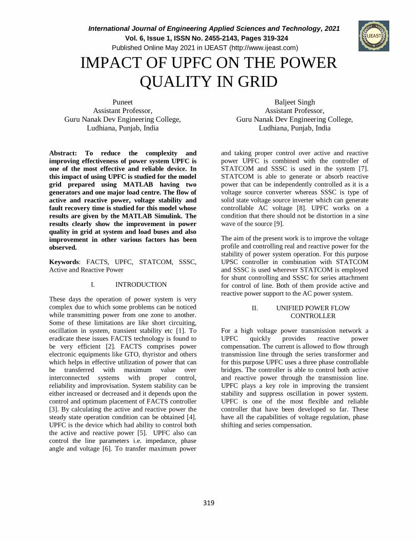
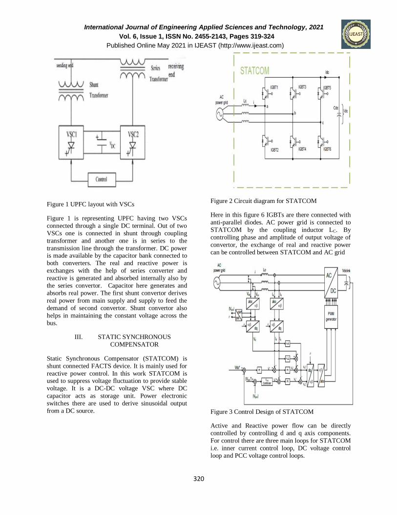
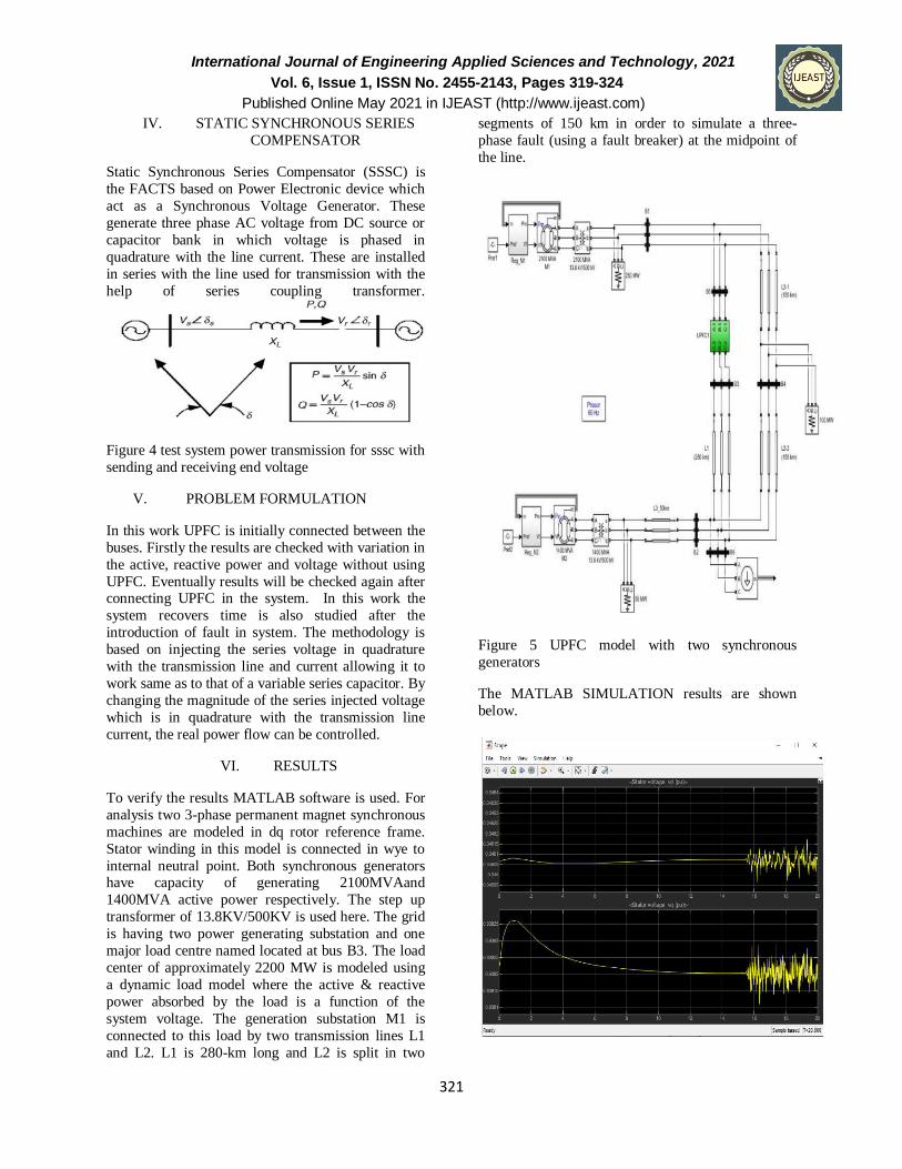
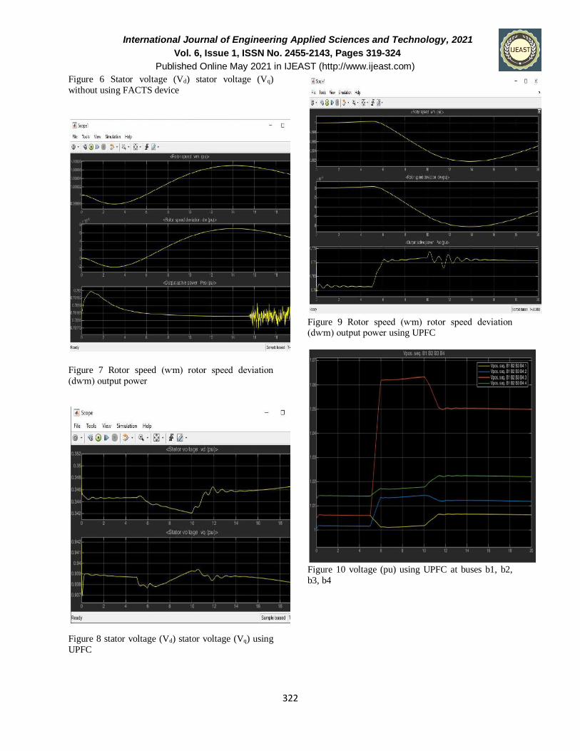
International Journal of Engineering Applied Sciences and Technology, 2021 Vol. 6, Issue 1, ISSN No. 2455-2143, Pages 319-324 Published Online May 2021 in IJEAST (http://www.ijeast.com) 319 IMPACT OF UPFC ON THE POWER QUALITY IN GRID Puneet Assistant Professor, Guru Nanak Dev Engineering College, Ludhiana, Punjab, India Baljeet Singh Assistant Professor, Guru Nanak Dev Engineering College, Ludhiana, Punjab, India Abstract: To reduce the complexity and improving effectiveness of power system UPFC is one of the most effective and reliable device. In this impact of using UPFC is studied for the model grid prepared using MATLAB having two generators and one major load centre. The flow of active and reactive power, voltage stability and fault recovery time is studied for this model whose results are given by the MATLAB Simulink. The results clearly show the improvement in power quality in grid at system and load buses and also improvement in other various factors has been observed. Keywords: FACTS, UPFC, STATCOM, SSSC, Active and Reactive Power I. INTRODUCTION These days the operation of power system is very complex due to which some problems can be noticed while transmitting power from one zone to another. Some of these limitations are like short circuiting, oscillation in system, transient stability etc [1]. To eradicate these issues FACTS technology is found to be very efficient [2]. FACTS comprises power electronic equipments like GTO, thyristor and others which helps in effective utilization of power that can be transferred with maximum value over interconnected systems with proper control, reliability and improvisation. System stability can be either increased or decreased and it depends upon the control and optimum placement of FACTS controller [3]. By calculating the active and reactive power the steady state operation condition can be obtained [4]. UPFC is the device which had ability to control both the active and reactive power [5]. UPFC also can control the line parameters i.e. impedance, phase angle and voltage [6]. To transfer maximum power and taking proper control over active and reactive power UPFC is combined with the controller of STATCOM and SSSC is used in the system [7]. STATCOM is able to generate or absorb reactive power that can be independently controlled as it is a voltage source converter whereas SSSC is type of solid state voltage source inverter which can generate controllable AC voltage [8]. UPFC works on a condition that there should not be distortion in a sine wave of the source [9]. The aim of the present work is to improve the voltage profile and controlling real and reactive power for the stability of power system operation. For this purpose UPSC controller in combination with STATCOM and SSSC is used wherever STATCOM is employed for shunt controlling and SSSC for series attachment for control of line. Both of them provide active and reactive power support to the AC power system. II. UNIFIED POWER FLOW CONTROLLER For a high voltage power transmission network a UPFC quickly provides reactive power compensation. The current is allowed to flow through transmission line through the series transformer and for this purpose UPFC uses a three phase controllable bridges. The controller is able to control both active and reactive power through the transmission line. UPFC plays a key role in improving the transient stability and suppress oscillation in power system. UPFC is one of the most flexible and reliable controller that have been developed so far. These have all the capabilities of voltage regulation, phase shifting and series compensation.
Transcript
International Journal of Engineering Applied Sciences and Technology, 2021