Page 1
1
Peter Heskes January 2011
The EOS LT project KTI is funded in part by SenterNovem
Minimizing the Impact of Resonances in
Low Voltage Grids
The KTI project
Grid impedance, interaction and resonances
Impedance measurement
Minimizing the impact of resonances
Contents
Page 2
2
The KTI project
Part 1: Research on new boundary conditions, social importance, consequences and
responsibilities.
(TU/e – EES group, Laborelec)
Part 2: Research on characteristics and
interactions between the grid and
connected appliances and generators
(ECN)
Part 3: Research on and development
of new power electronics to control the
quality of the voltage
(TU/e – EPE group)
Structure of the KTI project
Page 3
3
Publications
Journal articles
[1] P.J.M. Heskes, J.M.A. Myrzik, W.L. Kling, “Impact of Distribution System’s Non-Linear
Loads with Constant Power on Grid Voltage”, John Wiley ETEP Journal, in-Press.
[2] P.J.M. Heskes, J.M.A. Myrzik, W.L. Kling, “A Harmonic Impedance Measurement System
for Reduction of Harmonics in the Electricity Grid”, International Journal of Distributed
Energy Resources, vol. 5, no. 4, pp. 315-331, Oct./Dec. 2009.
Conference papers
[1] P.J.M. Heskes, J.M.A. Myrzik, W.L. Kling, “Ancillary Services for Minimizing the Impact of
Resonances in Low Voltage Grids by Power Electronics based Distributed Generators”, IEEE
Power Energy Systems General Meeting, Detroit, Michigan, USA, July 24-29, 2011, under review.
[2] P.J.M. Heskes, J.M.A. Myrzik, W.L. Kling, “Harmonic Distortion and Oscillatory Voltages and the
Role of Negative Impedance”, IEEE Power Energy Systems General Meeting, Minneapolis, USA,
July 25-29, 2010.
[3] P.J.M. Heskes, J.M.A. Myrzik, W.L. Kling, “Power Electronic Loads with Negative Differential
Impedance in a Low Voltage Distribution System”, 20th International Conference on Electricity
Distribution, Cired, Prague, 8-11 June 2009.
[5] P.J.M. Heskes, J.M.A. Myrzik, W.L. Kling, “Survey of Harmonic Reduction Techniques
Applicable as Ancillary Service of Dispersed Generators (DG)”, IEEE Young Researchers
Symposium, Technical University of Eindhoven, The Netherlands, February 7-8, 2008.
Grid impedance, interaction and resonances
Page 4
4
7 31-1-2011
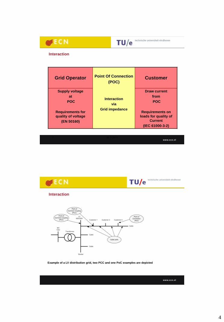
Grid Operator
Point Of Connection
(POC)
Interaction
via
Grid impedance
Customer
Supply voltage
at
POC
Requirements for
quality of voltage
(EN 50160)
Draw current
from
POC
Requirements on
loads for quality of
Current
(IEC 61000-3-2)
Interaction
Example of a LV distribution grid, two PCC and one PoC examples are depicted
Interaction
Page 5
5
Simplified grid model with a lumped large number of
resistive loads and parallel capacitances
Interaction
The grid loaded with a non-linear load
Interaction
Page 6
6
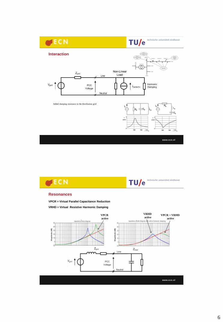
Added damping resistance in the distribution grid
Interaction
VPCR = Virtual Parallel Capacitance Reduction
Resonances
VRHD = Virtual Resistive Harmonic Damping
VPCR
active
VPCR + VRHD
active
VRHD
active
Page 7
7
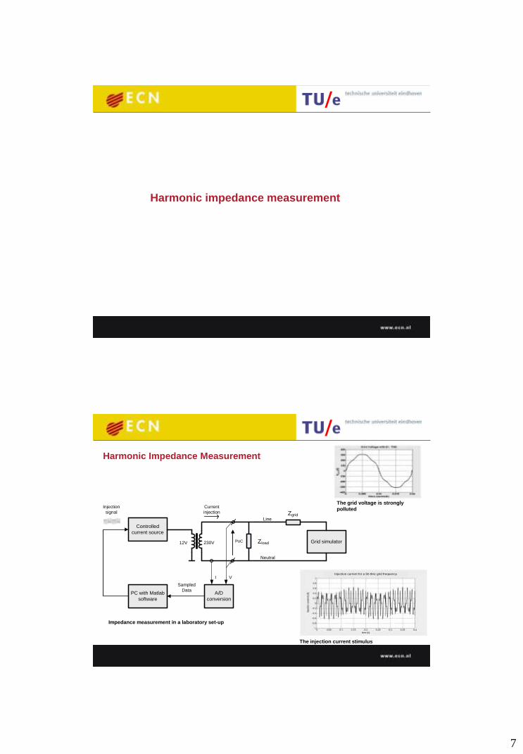
Harmonic impedance measurement
ZgridLine
Neutral
PoC Zload
Controlled
current source
Grid simulator
PC with Matlab
software
A/D
conversion
Sampled
Data
Injection
signal
VI
Current
injection
12V 230V
Injection current for a 50.0Hz grid frequency
The injection current stimulus
The grid voltage is strongly
polluted
Impedance measurement in a laboratory set-up
Harmonic Impedance Measurement
Page 8
8
Harmonic Impedance Measurement
The system:
• estimates free spots in freq. domain
• inject current on free spots
• collect voltage / current time series
• does domain transformation
• calculates the impedance spectrum
Shift
Measurement
frequencies
Start
Measure Voltage
Magnitude
Spectrum without
Stimulus
Voltage
Magnitude
Spectrum
below limit?
Inject a Current
signal to the grid
No
Calculate
Impedance
Spectrum
Measure Voltage
(and Current)
time series
Transformation to
frequency domain
Ancillary services for harmonic reduction
Page 9
9
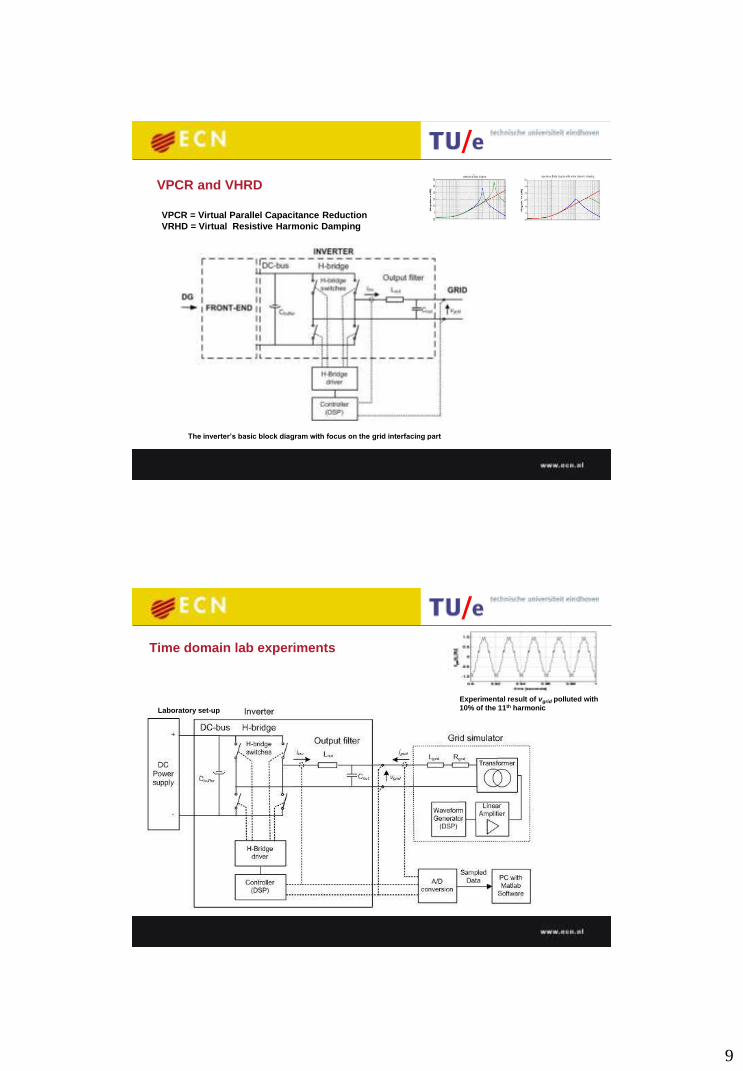
VPCR and VHRD
VPCR = Virtual Parallel Capacitance Reduction
VRHD = Virtual Resistive Harmonic Damping
The inverter’s basic block diagram with focus on the grid interfacing part
Time domain lab experiments
Laboratory set-up
Experimental result of vgrid polluted with
10% of the 11th harmonic
Page 10
10
inverter currents
VPCR = off
VRHD = off
Time domain lab experiments
1 1.02 1.04 1.06 1.08 1.1 -2
-1
0
1
2
i in
v (t)
1 1.02 1.04 1.06 1.08 1.1 -2
-1
0
1
2
I gri
d (
t)
time (seconds)
Experimental result of iinv and igrid without activated ancillary services
DC
Power
supply
model
Inverter model
iinv
vgrid
Output filter
model
H-Bridge
driver model
Controller
model
Lout
Cout
+
-
Lgrid Rgrid
Grid model
voltage
source
fundamental with 10%
of 11th harmonic
H-bridge
model
igrid
inverter currents
VPCR = on
VRHD = off
DC
Power
supply
model
Inverter model
iinv
vgrid
Output filter
model
H-Bridge
driver model
Controller
model
Lout
Cout
+
-
Lgrid Rgrid
Grid model
voltage
source
fundamental with 10%
of 11th harmonic
H-bridge
model
igrid
1 1.02 1.04 1.06 1.08 1.1 -2
-1
0
1
2
1 1.02 1.04 1.06 1.08 1.1 -2
-1
0
1
2
time (seconds)
i in
v (t)
I g
rid (
t)
Experimental result of iinv and igrid with activated VPCR
Time domain lab experiments
Page 11
11
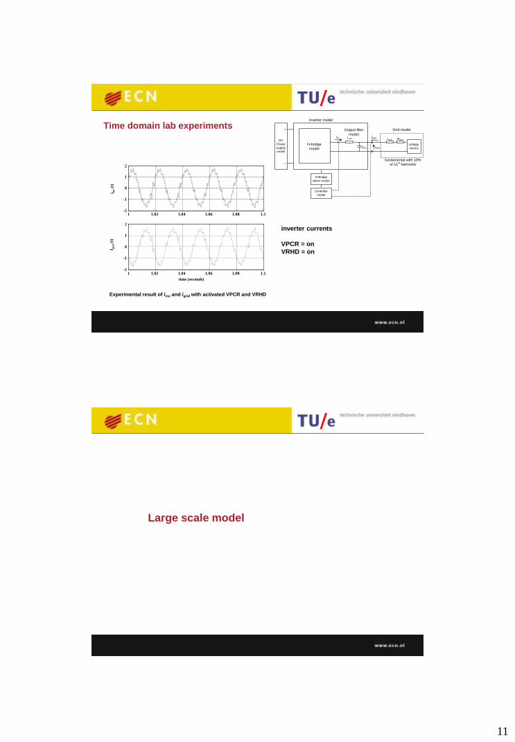
inverter currents
VPCR = on
VRHD = on
DC
Power
supply
model
Inverter model
iinv
vgrid
Output filter
model
H-Bridge
driver model
Controller
model
Lout
Cout
+
-
Lgrid Rgrid
Grid model
voltage
source
fundamental with 10%
of 11th harmonic
H-bridge
model
igrid
1 1.02 1.04 1.06 1.08 1.1 -2
-1
0
1
2
1 1.02 1.04 1.06 1.08 1.1 -2
-1
0
1
2
time (seconds)
I gri
d (
t)
i in
v (t)
Experimental result of iinv and igrid with activated VPCR and VRHD
Time domain lab experiments
Large scale model
Page 12
12
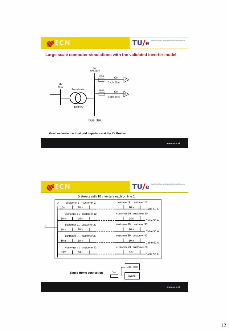
Large scale computer simulations with the validated inverter model
Goal: estimate the total grid impedance at the LV Busbar
Cable 50 Al
customer 11 customer 12 customer 19 customer 20
10m 10m 10m
customer 21 customer 22 customer 29 customer 30
10m 10m
customer 31 customer 32 customer 39 customer 40
10m 10m
customer 41 customer 42 customer 49 customer 50
10m 10m
Cable 50 Al
customer 1 customer 2 customer 9 customer 10
10m 10m10m
10m
10m
10m
Cable 50 Al
Cable 50 Al
Cable 50 Al
5 streets with 10 inverters each on line 1
A
A
Single Home connection Inverter
Cap. load
Zhome
Page 13
13
Inverter’s controller block with resonators on the fundamental
(50Hz) and the 3th, 5th, 7th, 9th and 11th harmonic.
The ancillary service inverter controls the (50Hz) and the 3th, 5th,
7th, 9th and 11th harmonic.
3 5 7 9 11
100 inverters + 100 capacitive
loads connected
Harmonic impedance measured at the substation busbar with
100 inverters as well as 100 capacitive loads connected.
5 7
3
9
11
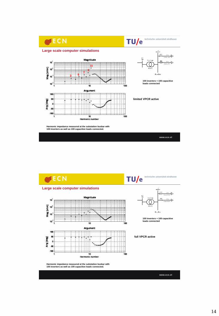
Large scale computer simulations
no ancillary services active
Page 14
14
100 inverters + 100 capacitive
loads connected
5 7
3
9
11
Large scale computer simulations
limited VPCR active
Harmonic impedance measured at the substation busbar with
100 inverters as well as 100 capacitive loads connected.
100 inverters + 100 capacitive
loads connected
full VPCR active
Large scale computer simulations
Harmonic impedance measured at the substation busbar with
100 inverters as well as 100 capacitive loads connected.
Page 15
15
100 inverters + 100 capacitive
loads connected
both VPCR and VRHD active
Large scale computer simulations
Harmonic impedance measured at the substation busbar with
100 inverters as well as 100 capacitive loads connected.
Author Name-Country-SessionX-
BlockY-Paper ID
30 P.J.M. Heskes Netherlands Session 2 Paper ID 0549
Conclusions
Based on study, simulations and laboratory measurements:
• VPCR virtually reduces capacitances that can bring resonances,
• VPCR + VRHD virtually reduces capacitances and damp resonances.
These two ancillary services can be implemented in power electronics
based inverters for DG. The actual working range depends on the
performance of the control system.
Page 16
16
Thank you for your kind
attention