61
1 Impala SS and Caprice T56 Six Speed install guide Created by: Mike Fetcko
1
Impala SS and Caprice T56 Six Speed install guide
Created by: Mike Fetcko
2
Intro
First let me tell you a little about myself. My name is Mike Fetcko and I live currently in Kalamazoo, Michigan. I am an Avionics Systems Engineer and work for a company that modifies business class jets. I got bitten by the B-Body bug a couple of years back when helping out my best friend with his 1996 Impala SS. Started digging into the car and before you knew it I was pretty fluent on the inner working, from suspension, engine, tranny, etc. I purchased my first 9C1 in 2007 for a whole 750 bucks. It is a 1994 model, which was pretty basic. Well it has undergone quite a few transformations since then. Paint, bodywork, T56 installation, engine mods (typical bolt on’s), suspension upgrade and all that jazz. I purchased another 1994 9C1 for a whole 250 bucks from Ebay, had about 182,000 miles on it now and ran like a champ. This was the quintessential winter beater, but it actually had a better body on it than my other 9C1 had on it, before bodywork. But it got totaled. I then purchased a 1995 Buick RMS, 123K original owner, no rust, winter ride. Didn’t run, but got that one for 450 bucks.
Well on with the guide. I want to document all that I have learned while doing
this installation on my car and all that I have learned from Impalassforum.com members along the way. I am not saying this is going to be the perfect guide but it will get you on track with what you need to do this installation yourself.
Torque specifications will be listed on page 38 for reference and also pictures
of some of the parts that you are going to need so that you have a visual reference.
3
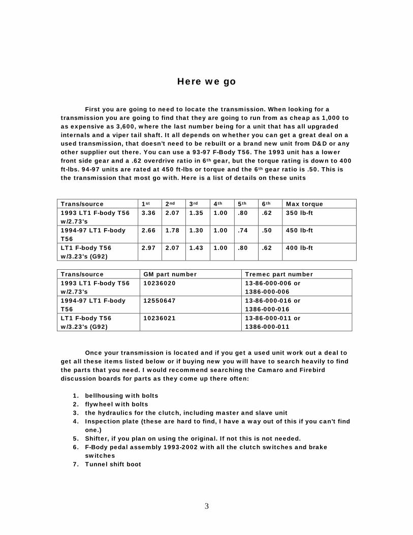
Here we go First you are going to need to locate the transmission. When looking for a transmission you are going to find that they are going to run from as cheap as 1,000 to as expensive as 3,600, where the last number being for a unit that has all upgraded internals and a viper tail shaft. It all depends on whether you can get a great deal on a used transmission, that doesn’t need to be rebuilt or a brand new unit from D&D or any other supplier out there. You can use a 93-97 F-Body T56. The 1993 unit has a lower front side gear and a .62 overdrive ratio in 6th gear, but the torque rating is down to 400 ft-lbs. 94-97 units are rated at 450 ft-lbs or torque and the 6th gear ratio is .50. This is the transmission that most go with. Here is a list of details on these units Trans/source 1st 2nd 3rd 4th 5th 6th Max torque 1993 LT1 F-body T56 w/2.73's
3.36 2.07 1.35 1.00 .80 .62 350 lb-ft
1994-97 LT1 F-body T56
2.66 1.78 1.30 1.00 .74 .50 450 lb-ft
LT1 F-body T56 w/3.23's (G92)
2.97 2.07 1.43 1.00 .80 .62 400 lb-ft
Trans/source GM part number Tremec part number 1993 LT1 F-body T56 w/2.73's
10236020 13-86-000-006 or 1386-000-006
1994-97 LT1 F-body T56
12550647 13-86-000-016 or 1386-000-016
LT1 F-body T56 w/3.23's (G92)
10236021 13-86-000-011 or 1386-000-011
Once your transmission is located and if you get a used unit work out a deal to get all these items listed below or if buying new you will have to search heavily to find the parts that you need. I would recommend searching the Camaro and Firebird discussion boards for parts as they come up there often:
1. bellhousing with bolts 2. flywheel with bolts 3. the hydraulics for the clutch, including master and slave unit 4. Inspection plate (these are hard to find, I have a way out of this if you can’t find
one.) 5. Shifter, if you plan on using the original. If not this is not needed. 6. F-Body pedal assembly 1993-2002 with all the clutch switches and brake
switches 7. Tunnel shift boot
4
8. And all the switches and connectors from the transmission including: reverse lockout, VSS connector (if you have a 94 or 95 car, if you have a 96 the original connector will plug right in.) and Reverse lights.
This should be all that you need from an F-body donor car to start your B-bodies transformation.
Now listed below are the items that you are going to have to purchase to install the T56 into your B-Body.
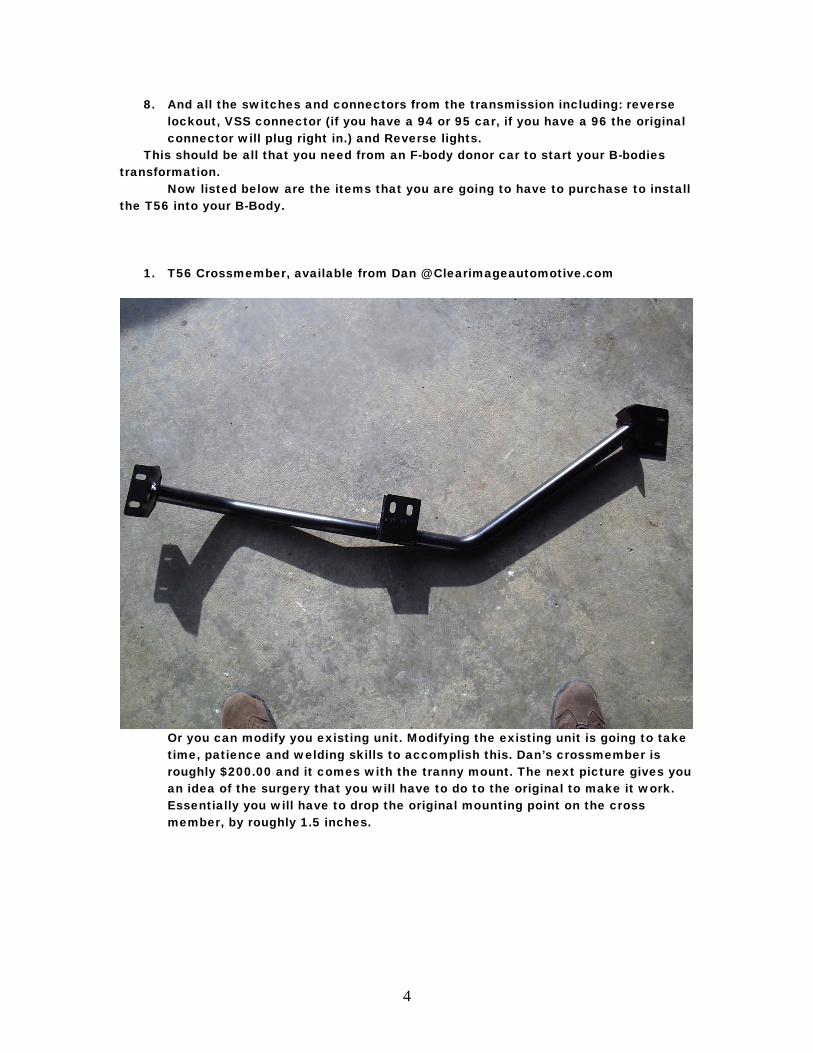
1. T56 Crossmember, available from Dan @ Clearimageautomotive.com
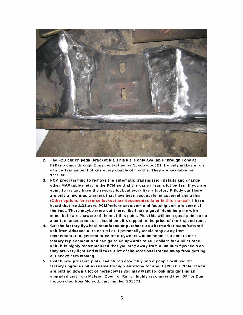
Or you can modify you existing unit. Modifying the existing unit is going to take time, patience and welding skills to accomplish this. Dan’s crossmember is roughly $200.00 and it comes with the tranny mount. The next picture gives you an idea of the surgery that you will have to do to the original to make it work. Essentially you will have to drop the original mounting point on the cross member, by roughly 1.5 inches.
5
2. The F2B clutch pedal bracket kit. This kit is only available through Tony at
F2Bkit.comor through Ebay contact seller Scoobydoo321. He only makes a run of a certain amount of kits every couple of months. They are available for $415.00.
3. PCM programming to remove the automatic transmission details and change other MAF tables, etc. in the PCM so that the car will run a lot better. If you are going to try and have the reverse lockout work like a factory F-Body car there are only a few programmers that have been successful in accomplishing this. (Other options for reverse lockout are documented later in this manual) I have heard that madz28.com, PCMPerformance.com and fastchip.com are some of the best. There maybe more out there, like I had a good friend help me with mine, but I am unaware of them at this point. Plus this will be a good point to do a performance tune as it should be all wrapped in the price of the 6 speed tune.
4. Get the factory flywheel resurfaced or purchase an aftermarket manufactured unit from Advance auto or similar, I personally would stay away from remanufactured, general price for a flywheel will be about 100 dollars for a factory replacement and can go to an upwards of 600 dollars for a billet steel unit, it is highly recommended that you stay away from aluminum flywheels as they are very light and will take a lot of the rotational torque away from getting our heavy cars moving.
5. Install new pressure plate and clutch assembly, most people will use the factory upgrade unit available through Autozone for about $200.00. Note: If you are putting down a lot of horsepower you may want to look into getting an upgraded unit from Mcleod, Zoom or Ram. I highly recommend the “DF” or Dual friction disc from Mcleod, part number 261571.
6
6. Install new gears, I would recommend at least 4.10’s. Other guys have run 3.73’s and 4.56’s with great luck. I like the 4.10’s personally, because it gives you great off the line characteristics and great cruising RPM. Yes you can run the 3.08’s, but be warned doing this can cause damage to your engine by bogging it too much and also damaging the clutch from having to rev so high to get it going.
7. If doing the gears, which are RECOMMENDED, you need a new driveshaft. Denny’s driveshaft in New York makes about the best ones and he is one of two in the country that can spin the shaft to its critical speed and balance it. He should have the measurements from my car, but stock length will work fine and also if you have extended control arms, make sure that you add this length. Most likely Denny will require you to measure it anyway. He can be contacted at dennysdrishaft.com
Listed below are Gm factory part numbers and quantities that gm originally used, that you can use if you are missing something that was described above, prices listed are pretty generic and there is no guarantee that the manufacturer still carries these items:
• 1- 10267518 Transmission Boot Underbody $24.18 (seals around shifter coming through car) Note: this item has been discontinued, used will be the only option for this or you will have to get creative with making a boot.
• 1- 12101899 Vss Pigtail • 1- 12101857 Reverse Lockout Pigtail $10.76 • 1- 12085485 Reverse Light Pigtail $10.40 • 4 - 12337828 Screws for flywheel cover $0.37 • 1 - 10241153 cover for flywheel (dust shield AKA flywheel access panel)
Discontinued, only used available see below for alternate method or contact Tony at F2Bkit.com as he manufactures replacements of this unit.
• 6 - 12337973 bolt for flywheel $1.34 • 6 - 10079898 bolt for pressure plate to flywheel $1.78
Note: I have been informed that these are no longer available and have been discontinued; ARP may make replacements for these
• 6 - 10198997 bolt for bell housing to engine $0.43 • 1 - 12559912 master/slave clutch cylinder $98.24 • 2 - 11506117 nut for slave cylinder M8x1.25/with washer • 1 - 10121502 retainer for clutch reservoir $0.17 • 2 - 22570841 bolt for transmission mount M10x1.5x30 • 1 - 10255857 nut for transmission mount $1.28
7
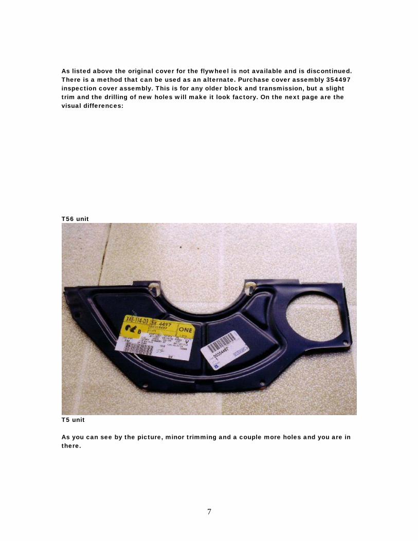
As listed above the original cover for the flywheel is not available and is discontinued. There is a method that can be used as an alternate. Purchase cover assembly 354497 inspection cover assembly. This is for any older block and transmission, but a slight trim and the drilling of new holes will make it look factory. On the next page are the visual differences:
T56 unit
T5 unit As you can see by the picture, minor trimming and a couple more holes and you are in there.
8
Installation
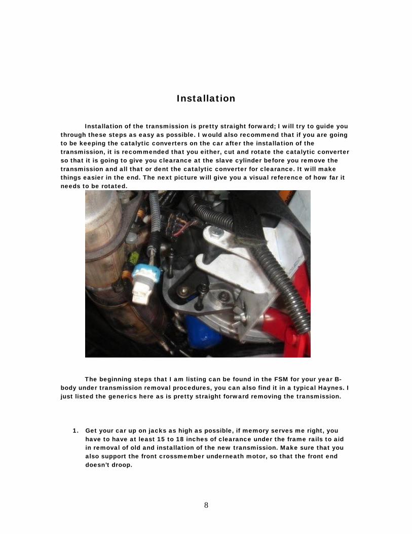
Installation of the transmission is pretty straight forward; I will try to guide you through these steps as easy as possible. I would also recommend that if you are going to be keeping the catalytic converters on the car after the installation of the transmission, it is recommended that you either, cut and rotate the catalytic converter so that it is going to give you clearance at the slave cylinder before you remove the transmission and all that or dent the catalytic converter for clearance. It will make things easier in the end. The next picture will give you a visual reference of how far it needs to be rotated.
The beginning steps that I am listing can be found in the FSM for your year B-
body under transmission removal procedures, you can also find it in a typical Haynes. I just listed the generics here as is pretty straight forward removing the transmission.
1. Get your car up on jacks as high as possible, if memory serves me right, you
have to have at least 15 to 18 inches of clearance under the frame rails to aid in removal of old and installation of the new transmission. Make sure that you also support the front crossmember underneath motor, so that the front end doesn’t droop.
9
2. Take measurement from yoke, at the transmission connected to the driveshaft, to the floor; make sure this is exact, as this is the measurement you are going to need to go by when installing the new transmission to height, so that you don’t have to mess with the pinion angle. You can also use an angle finder to get the angle off of the harmonic balancer and make a note of this angle.
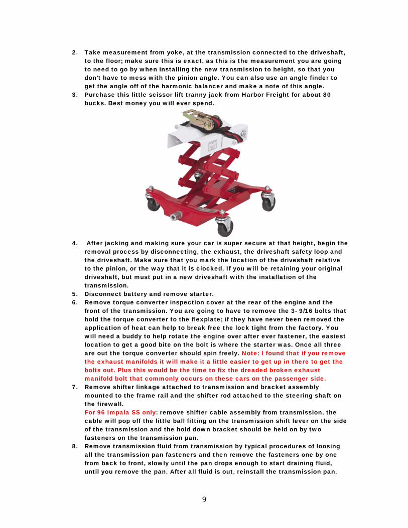
3. Purchase this little scissor lift tranny jack from Harbor Freight for about 80 bucks. Best money you will ever spend.
4. After jacking and making sure your car is super secure at that height, begin the
removal process by disconnecting, the exhaust, the driveshaft safety loop and the driveshaft. Make sure that you mark the location of the driveshaft relative to the pinion, or the way that it is clocked. If you will be retaining your original driveshaft, but must put in a new driveshaft with the installation of the transmission.
5. Disconnect battery and remove starter. 6. Remove torque converter inspection cover at the rear of the engine and the
front of the transmission. You are going to have to remove the 3- 9/16 bolts that hold the torque converter to the flexplate; if they have never been removed the application of heat can help to break free the lock tight from the factory. You will need a buddy to help rotate the engine over after ever fastener, the easiest location to get a good bite on the bolt is where the starter was. Once all three are out the torque converter should spin freely. Note: I found that if you remove the exhaust manifolds it will make it a little easier to get up in there to get the bolts out. Plus this would be the time to fix the dreaded broken exhaust manifold bolt that commonly occurs on these cars on the passenger side.
7. Remove shifter linkage attached to transmission and bracket assembly mounted to the frame rail and the shifter rod attached to the steering shaft on the firewall. For 96 Impala SS only: remove shifter cable assembly from transmission, the cable will pop off the little ball fitting on the transmission shift lever on the side of the transmission and the hold down bracket should be held on by two fasteners on the transmission pan.
8. Remove transmission fluid from transmission by typical procedures of loosing all the transmission pan fasteners and then remove the fasteners one by one from back to front, slowly until the pan drops enough to start draining fluid, until you remove the pan. After all fluid is out, reinstall the transmission pan.
10
9. Place jack under transmission, remove transmission mount nut, 5/8 on crossmember mount and relieve pressure off crossmember by jacking up transmission as high as it will go to give you room to get crossmember out.
10. Remove four 15mm bolts total in the frame rails themselves, two on each side, holding the crossmember in place. Now pray to the Gods that you will not have to cuss too much getting the original crossmember. What I have found works is you push forward and into the frame rail on the drivers side and pull back on the passenger side and it should fall out. Just cross your fingers. Note: that if you are doing this installation on a Caprice with heavy duty tow package and a mechanical fan, remove the fan shroud before dropping the transmission down, the fan will hit the shroud if you don’t do this.
11. Now that crossmember is removed, drop transmission down as low as it will go and remove transmission cooler lines, this is where I would recommend removing the exhaust manifolds or the catalytic converters , so that you can get in there to break them free. If you can’t break them loose you can cut them, as you will not need these anymore. Note: Have a drop pan handy as transmission fluid will run out of the lines. This is the time you can remove the transmission cooler lines and cooler itself, or just remove the lines and reuse the cooler for a power steering cooler. I will document this in the end of the manual. Note that if you are doing this installation on a Caprice with heavy duty tow package and a mechanical fan, remove the fan shroud before dropping the transmission down, the fan will hit the shroud if you don’t do this.
12. Disconnect all connectors on transmission, the big round one on the passenger side is removed by squeezing the sides and pulling up. VSS is at the tail shaft and also the temp sender attached to fluid lines. Disconnect the connectors and essentially have the harness completely loose up to the back of the engine block. Note: On 96 models with four O2 sensors, the rear sensors are part of this harness and will have to be disconnected, make sure these are marked where they go.
13. Begin removing, with a really long extension, the six 9/16 bellhousing bolts holding the transmission to the back of the block and the bolt that holds the transmission dipstick tube to the passenger side head and push up the tube as far as it will go. Go from top to bottom, once the top bolts are loose and free, jack transmission back up to about level and remove the remaining lower bolts.
14. Once all the bolts are out there are two dowel pins that hold the transmission in place, you may have to wiggle the transmission back and forth to get it out but it will come out, lower and wheel out from underneath the car. Note: I recommend placing a woodblock on a jackstand and place this under the oil pan so when the transmission is pulled from the dowels the engine won’t be resting fully on the engine mounts alone.
11
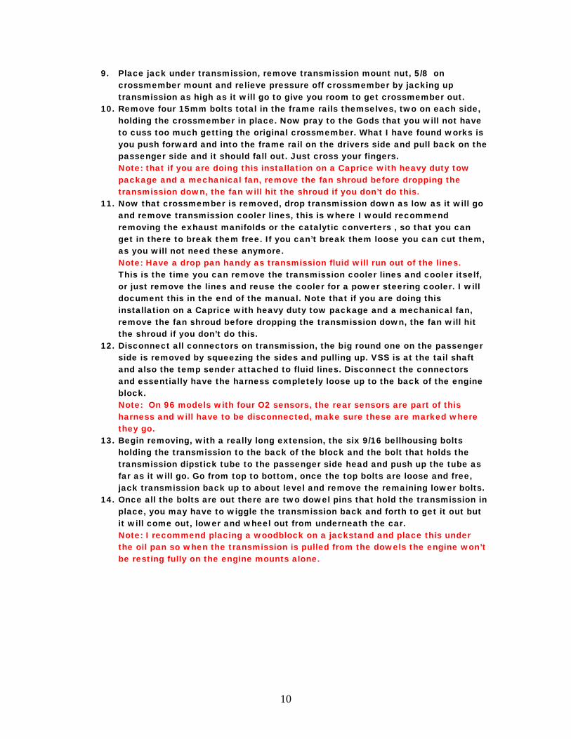
15. Take the old transmission dipstick out as viewed in next picture, you are going
to have to cut the wire harness hold down portion off to re use to save your wiring from falling down on exhaust manifold.
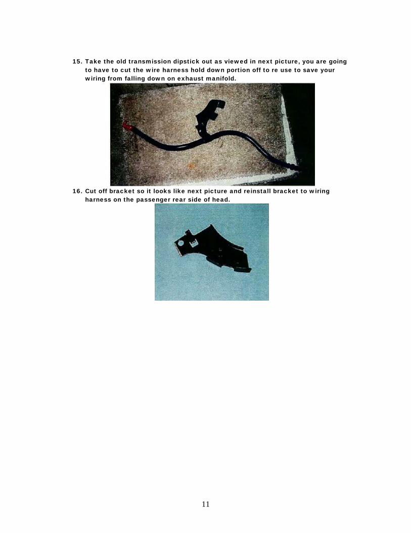
16. Cut off bracket so it looks like next picture and reinstall bracket to wiring
harness on the passenger rear side of head.
12
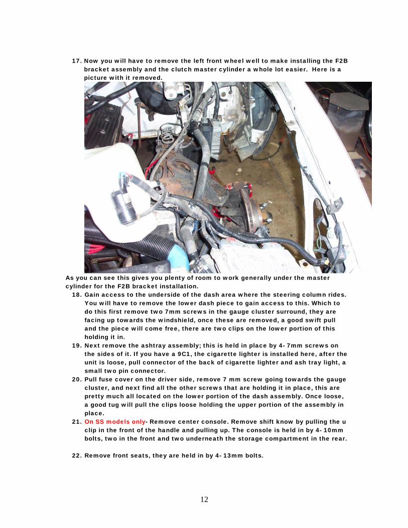
17. Now you will have to remove the left front wheel well to make installing the F2B
bracket assembly and the clutch master cylinder a whole lot easier. Here is a picture with it removed.
As you can see this gives you plenty of room to work generally under the master cylinder for the F2B bracket installation.
18. Gain access to the underside of the dash area where the steering column rides. You will have to remove the lower dash piece to gain access to this. Which to do this first remove two 7mm screws in the gauge cluster surround, they are facing up towards the windshield, once these are removed, a good swift pull and the piece will come free, there are two clips on the lower portion of this holding it in.
19. Next remove the ashtray assembly; this is held in place by 4- 7mm screws on the sides of it. If you have a 9C1, the cigarette lighter is installed here, after the unit is loose, pull connector of the back of cigarette lighter and ash tray light, a small two pin connector.
20. Pull fuse cover on the driver side, remove 7 mm screw going towards the gauge cluster, and next find all the other screws that are holding it in place, this are pretty much all located on the lower portion of the dash assembly. Once loose, a good tug will pull the clips loose holding the upper portion of the assembly in place.
21. On SS models only- Remove center console. Remove shift know by pulling the u clip in the front of the handle and pulling up. The console is held in by 4- 10mm bolts, two in the front and two underneath the storage compartment in the rear.
22. Remove front seats, they are held in by 4- 13mm bolts.
13
23. Remove door sill plates that are holding down the carpet, pull carpet back to give you ample room to access center tunnel, where the shifter is going to lie.
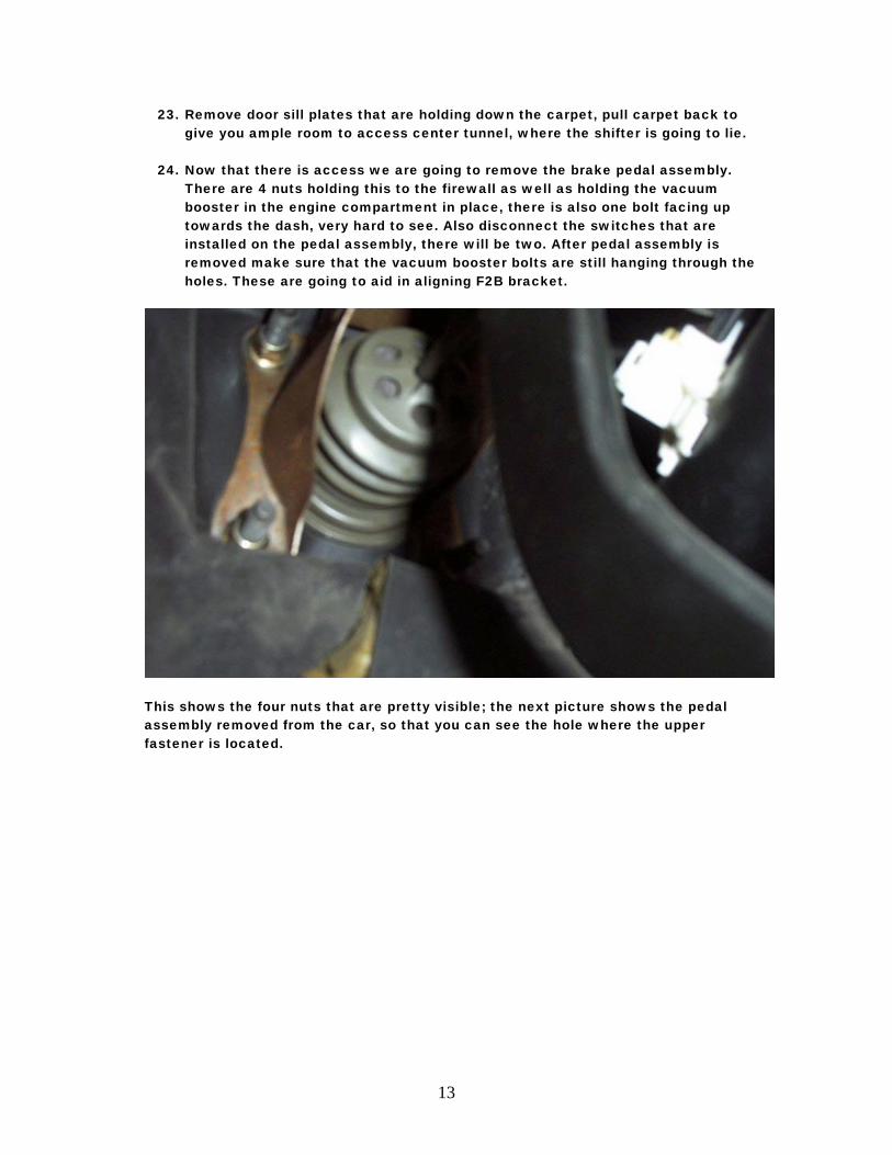
24. Now that there is access we are going to remove the brake pedal assembly.
There are 4 nuts holding this to the firewall as well as holding the vacuum booster in the engine compartment in place, there is also one bolt facing up towards the dash, very hard to see. Also disconnect the switches that are installed on the pedal assembly, there will be two. After pedal assembly is removed make sure that the vacuum booster bolts are still hanging through the holes. These are going to aid in aligning F2B bracket.
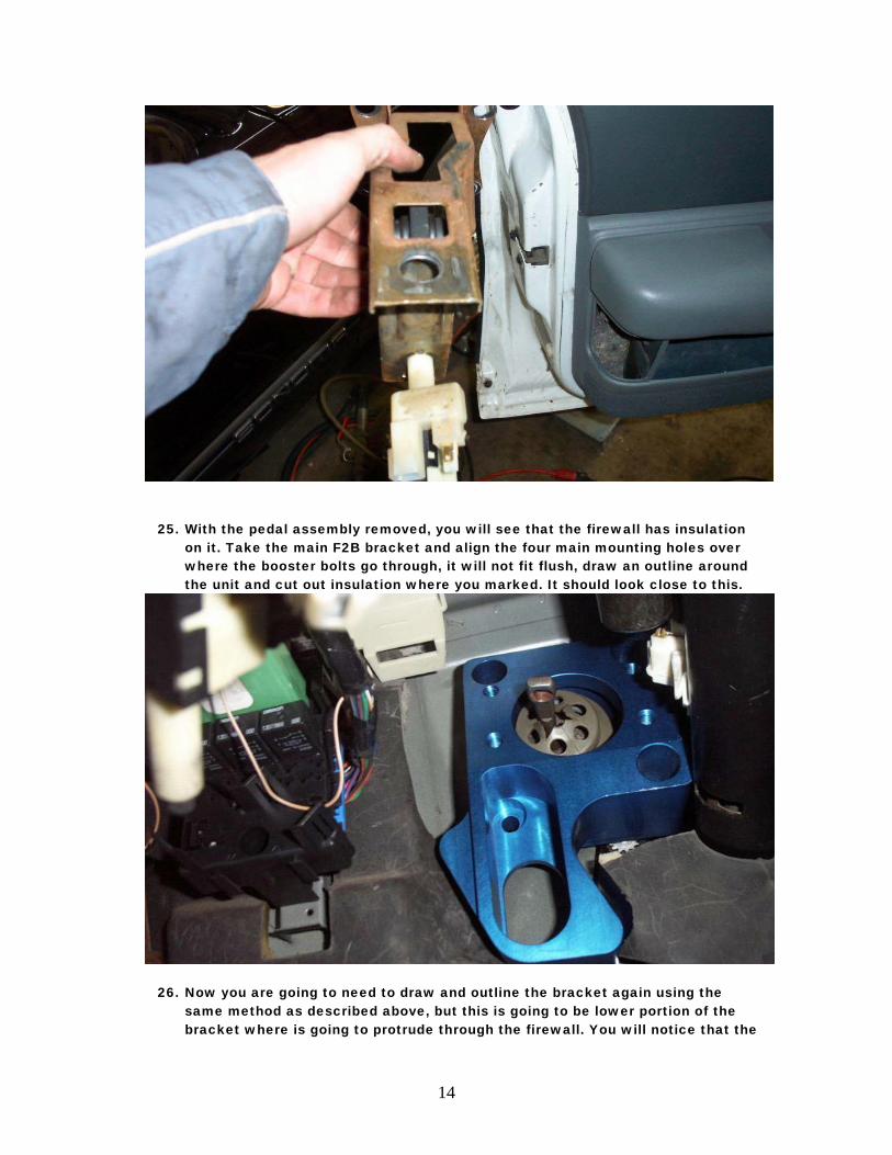
This shows the four nuts that are pretty visible; the next picture shows the pedal assembly removed from the car, so that you can see the hole where the upper fastener is located.
14
25. With the pedal assembly removed, you will see that the firewall has insulation on it. Take the main F2B bracket and align the four main mounting holes over where the booster bolts go through, it will not fit flush, draw an outline around the unit and cut out insulation where you marked. It should look close to this.
26. Now you are going to need to draw and outline the bracket again using the same method as described above, but this is going to be lower portion of the bracket where is going to protrude through the firewall. You will notice that the
15
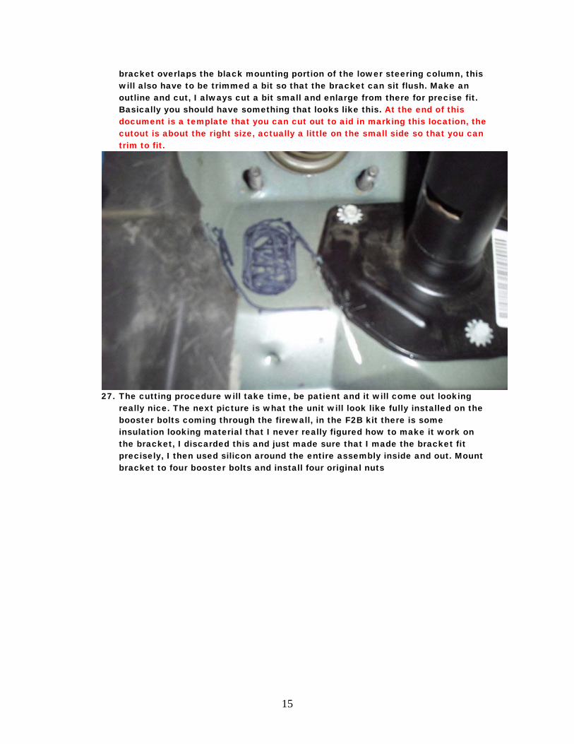
bracket overlaps the black mounting portion of the lower steering column, this will also have to be trimmed a bit so that the bracket can sit flush. Make an outline and cut, I always cut a bit small and enlarge from there for precise fit. Basically you should have something that looks like this. At the end of this document is a template that you can cut out to aid in marking this location, the cutout is about the right size, actually a little on the small side so that you can trim to fit.
27. The cutting procedure will take time, be patient and it will come out looking
really nice. The next picture is what the unit will look like fully installed on the booster bolts coming through the firewall, in the F2B kit there is some insulation looking material that I never really figured how to make it work on the bracket, I discarded this and just made sure that I made the bracket fit precisely, I then used silicon around the entire assembly inside and out. Mount bracket to four booster bolts and install four original nuts
16
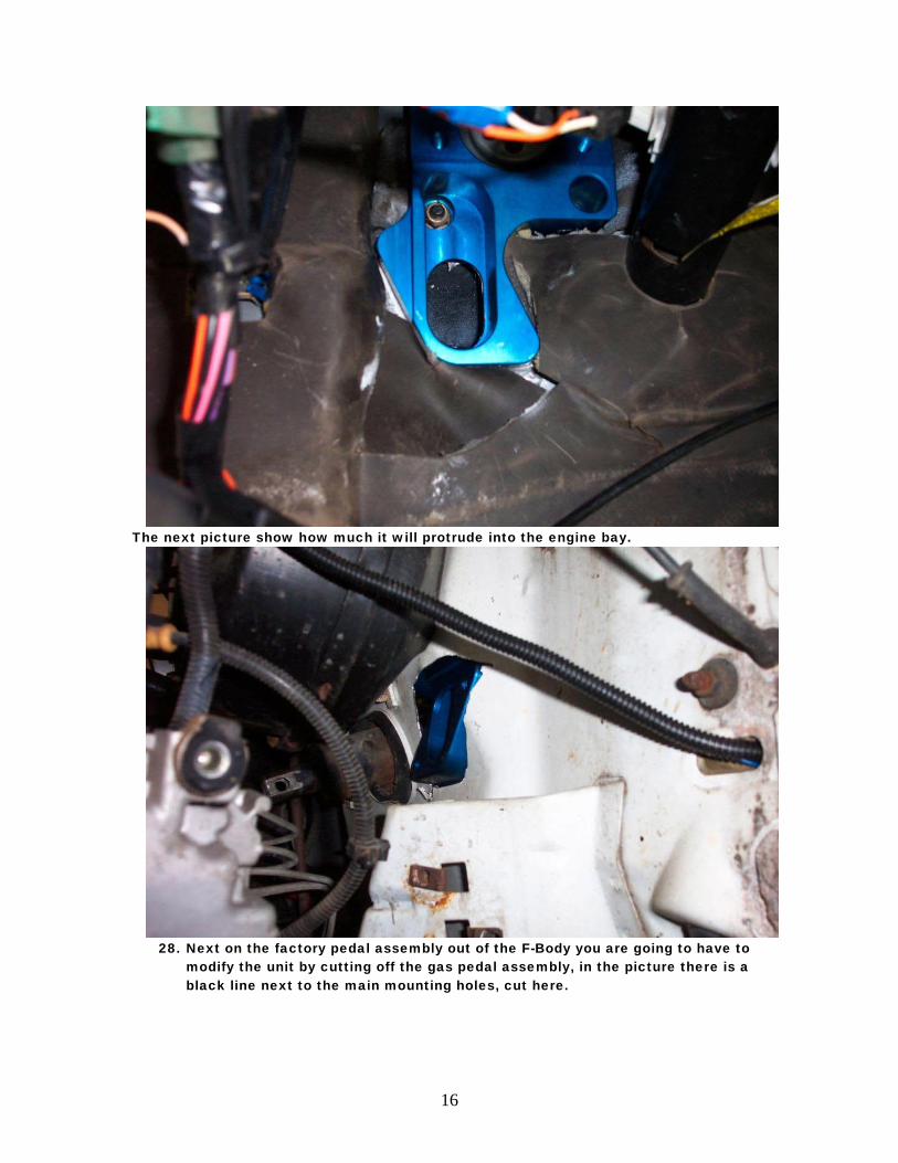
The next picture show how much it will protrude into the engine bay.
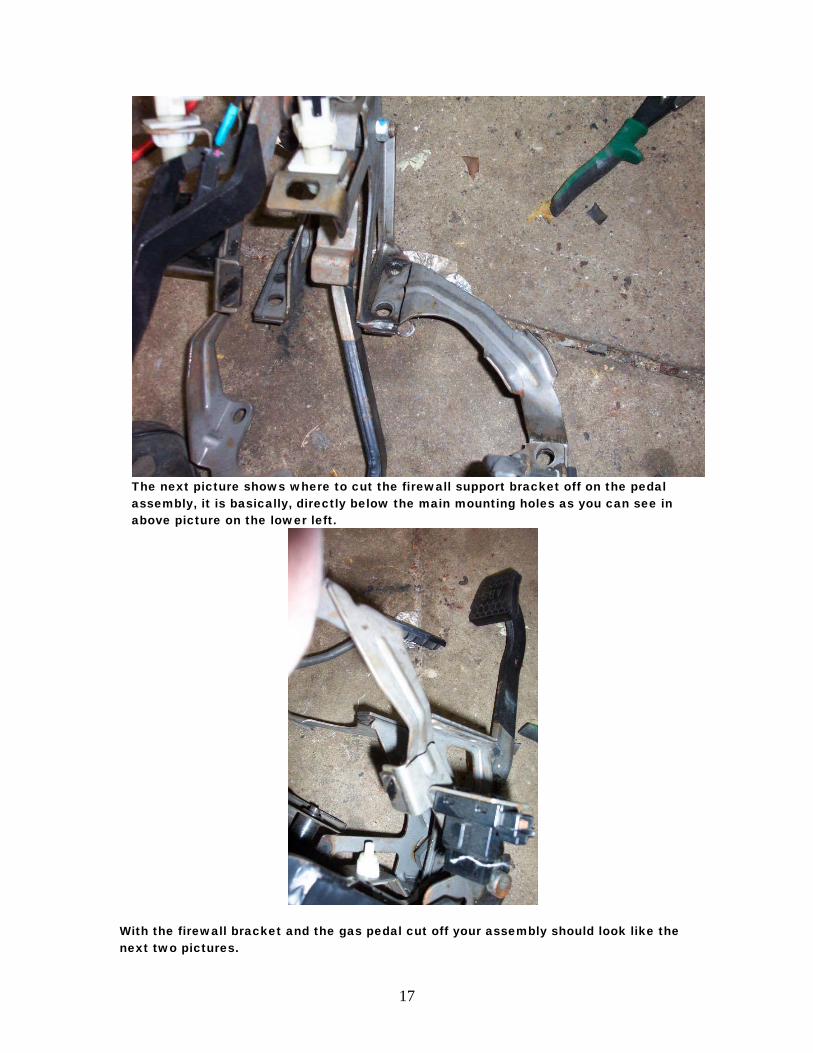
28. Next on the factory pedal assembly out of the F-Body you are going to have to
modify the unit by cutting off the gas pedal assembly, in the picture there is a black line next to the main mounting holes, cut here.
17
The next picture shows where to cut the firewall support bracket off on the pedal assembly, it is basically, directly below the main mounting holes as you can see in above picture on the lower left.
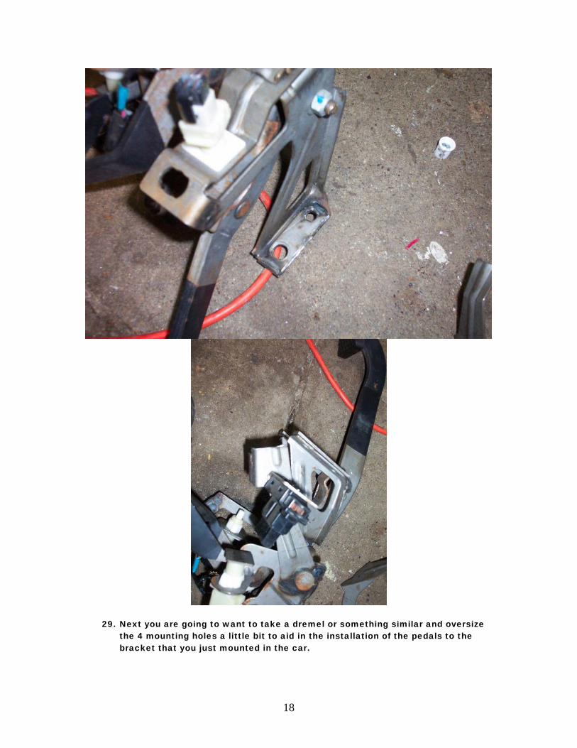
With the firewall bracket and the gas pedal cut off your assembly should look like the next two pictures.
18
29. Next you are going to want to take a dremel or something similar and oversize the 4 mounting holes a little bit to aid in the installation of the pedals to the bracket that you just mounted in the car.
19
30. Next remove the two existing brake pedal switches from the original pedal assembly along with the clips that mount them to it and install on the F-Body assembly.
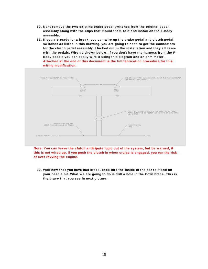
31. If you are ready for a break, you can wire up the brake pedal and clutch pedal switches as listed in this drawing, you are going to need to get the connectors for the clutch pedal assembly. I lucked out in the installation and they all came with the pedals. Wire as shown below. If you don’t have the harness from the F-Body pedals you can easily wire it using this diagram and an ohm meter. Attached at the end of this document is the full fabrication procedure for this wiring modification.
Note: You can leave the clutch anticipate logic out of the system, but be warned, if this is not wired up, if you push the clutch in when cruise is engaged, you run the risk of over revving the engine.
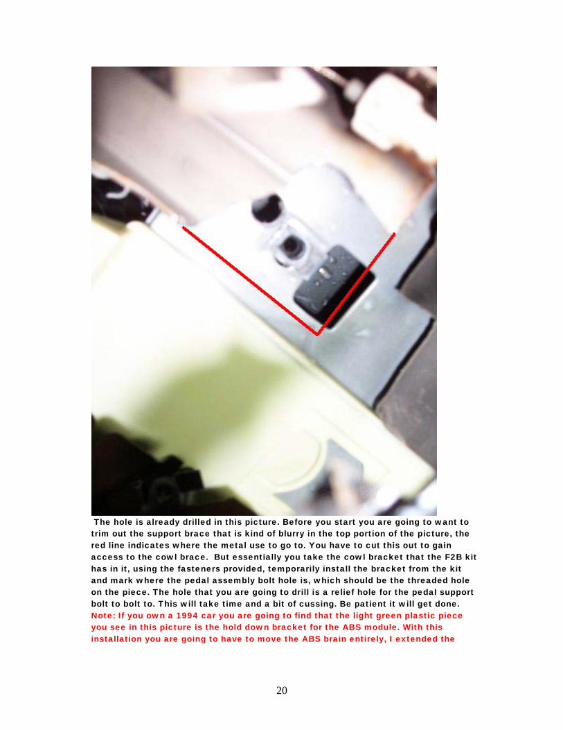
32. Well now that you have had break, back into the inside of the car to stand on your head a bit. What we are going to do is drill a hole in the Cowl brace. This is the brace that you see in next picture.
20
The hole is already drilled in this picture. Before you start you are going to want to trim out the support brace that is kind of blurry in the top portion of the picture, the red line indicates where the metal use to go to. You have to cut this out to gain access to the cowl brace. But essentially you take the cowl bracket that the F2B kit has in it, using the fasteners provided, temporarily install the bracket from the kit and mark where the pedal assembly bolt hole is, which should be the threaded hole on the piece. The hole that you are going to drill is a relief hole for the pedal support bolt to bolt to. This will take time and a bit of cussing. Be patient it will get done. Note: If you own a 1994 car you are going to find that the light green plastic piece you see in this picture is the hold down bracket for the ABS module. With this installation you are going to have to move the ABS brain entirely, I extended the
21
wiring to mine and put it behind where the ashtray used to go in my car. You may have to come up with something creative on this one.
33. After you got the hole drilled and all the process listed before complete install the cowl bracket into where you were just at, using provided fasteners in the kit.
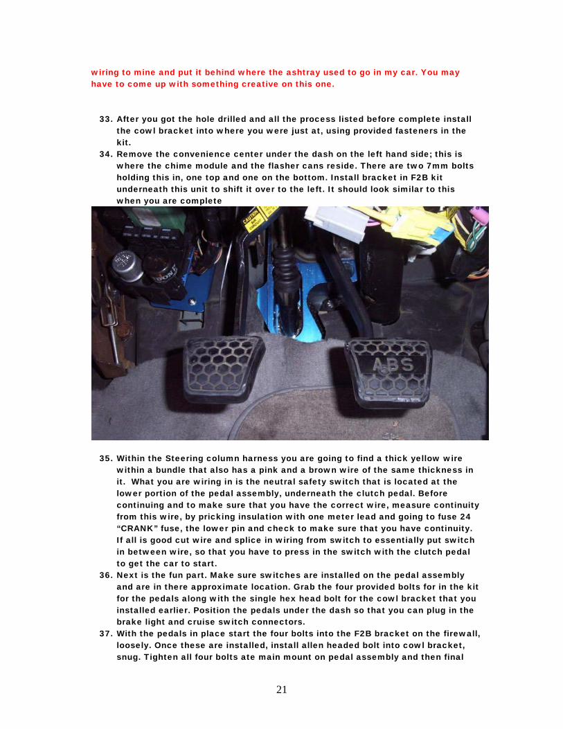
34. Remove the convenience center under the dash on the left hand side; this is where the chime module and the flasher cans reside. There are two 7mm bolts holding this in, one top and one on the bottom. Install bracket in F2B kit underneath this unit to shift it over to the left. It should look similar to this when you are complete
35. Within the Steering column harness you are going to find a thick yellow wire within a bundle that also has a pink and a brown wire of the same thickness in it. What you are wiring in is the neutral safety switch that is located at the lower portion of the pedal assembly, underneath the clutch pedal. Before continuing and to make sure that you have the correct wire, measure continuity from this wire, by pricking insulation with one meter lead and going to fuse 24 “CRANK” fuse, the lower pin and check to make sure that you have continuity. If all is good cut wire and splice in wiring from switch to essentially put switch in between wire, so that you have to press in the switch with the clutch pedal to get the car to start.
36. Next is the fun part. Make sure switches are installed on the pedal assembly and are in there approximate location. Grab the four provided bolts for in the kit for the pedals along with the single hex head bolt for the cowl bracket that you installed earlier. Position the pedals under the dash so that you can plug in the brake light and cruise switch connectors.
37. With the pedals in place start the four bolts into the F2B bracket on the firewall, loosely. Once these are installed, install allen headed bolt into cowl bracket, snug. Tighten all four bolts ate main mount on pedal assembly and then final
22
tighten the cowl bracket bolt. There you have it bracket and pedals are all installed.
38. For 1996 Impalas only you are going to have to splice some wiring at the center console. Splice together the PNP switch wiring, which should be yellow and purple. Also splice the orange/black wire to the black/white wire for the trunk release. ON 94 and 95 models, leaving the shifter bowl on the column in the park position will accomplish the same thing. The only thing that you have to do is pop out the pin, from the bottom, holding the column shifter in place. If you choose to splice the wiring in a 94 or 95 car, you can do this also. The color coding will match the 96 Impala it is just on the column switch instead of in the center console area.
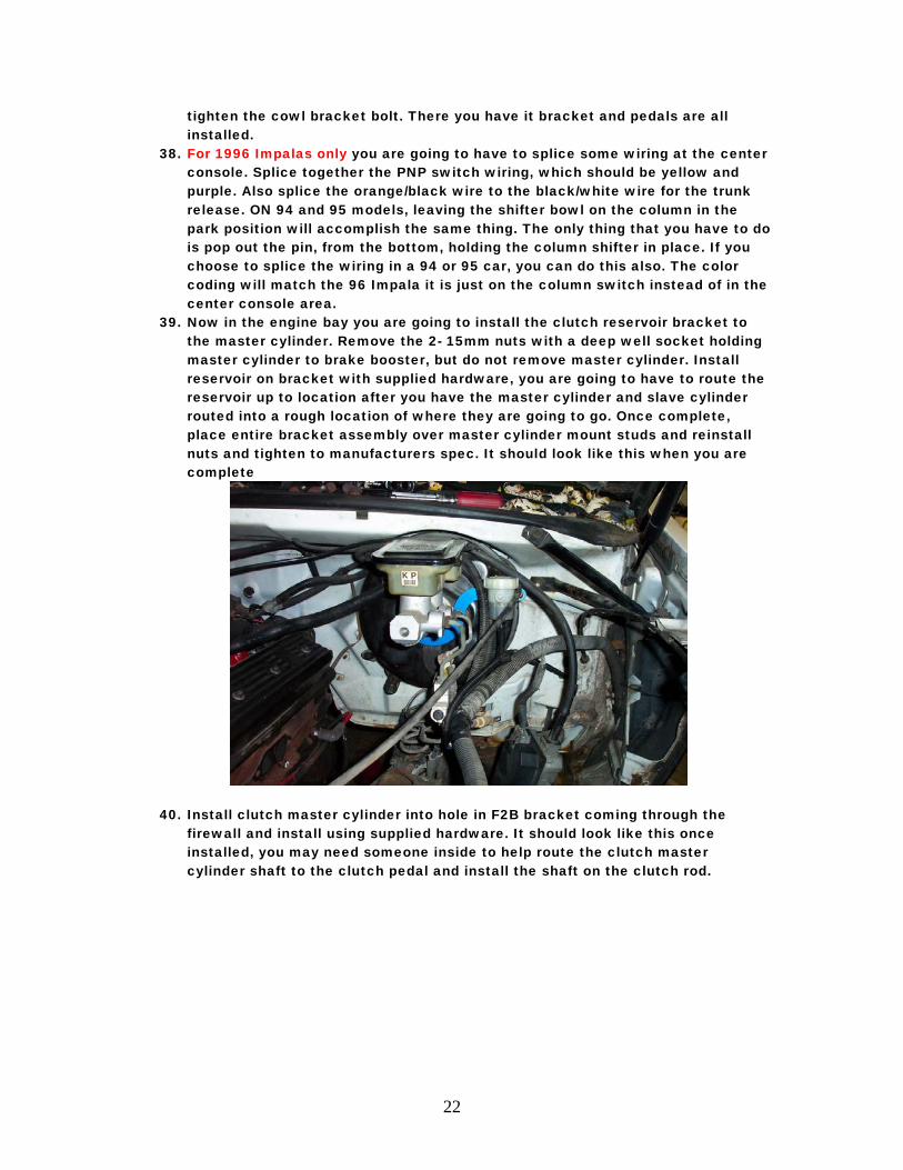
39. Now in the engine bay you are going to install the clutch reservoir bracket to the master cylinder. Remove the 2- 15mm nuts with a deep well socket holding master cylinder to brake booster, but do not remove master cylinder. Install reservoir on bracket with supplied hardware, you are going to have to route the reservoir up to location after you have the master cylinder and slave cylinder routed into a rough location of where they are going to go. Once complete, place entire bracket assembly over master cylinder mount studs and reinstall nuts and tighten to manufacturers spec. It should look like this when you are complete
40. Install clutch master cylinder into hole in F2B bracket coming through the firewall and install using supplied hardware. It should look like this once installed, you may need someone inside to help route the clutch master cylinder shaft to the clutch pedal and install the shaft on the clutch rod.
23
41. Install retaining clip on rod on clutch pedal to hold master cylinder shaft in place.
42. Route slave cylinder down towards transmission and let it hang out of the way. 43. Ok now up to getting everything cut for the transmission installation. What you
are going to need to do is get the transmission on either the jack that I indicated previously, or something to jack it in place. Temporarily put the bellhousing on the transmission by putting enough bolts in the transmission to bellhousing to support weight of the transmission and take a measurement from the face of the bellhousing to the back of the shifter box on the transmission, you are going to want to make several measurements of this and draw it out on the underside of the car and cut the hole in the floor, another method that many have used is install transmission temporarily on the motor, with out the clutch installed, align bellhousing to dowel pins on the back of the engine block and slide on transmission, it should install fairly easily on the dowel pins and install at least four of the 9/16 bolts on the sides of the bellhousing to hold the unit in place.
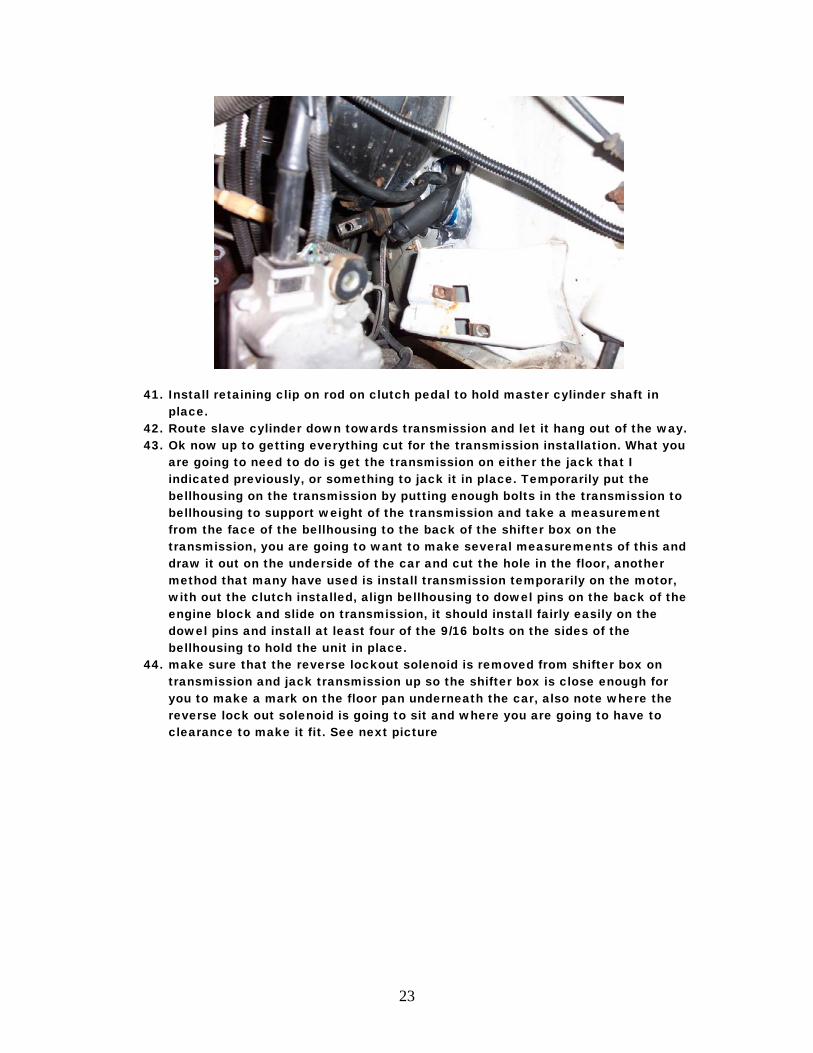
44. make sure that the reverse lockout solenoid is removed from shifter box on transmission and jack transmission up so the shifter box is close enough for you to make a mark on the floor pan underneath the car, also note where the reverse lock out solenoid is going to sit and where you are going to have to clearance to make it fit. See next picture
24
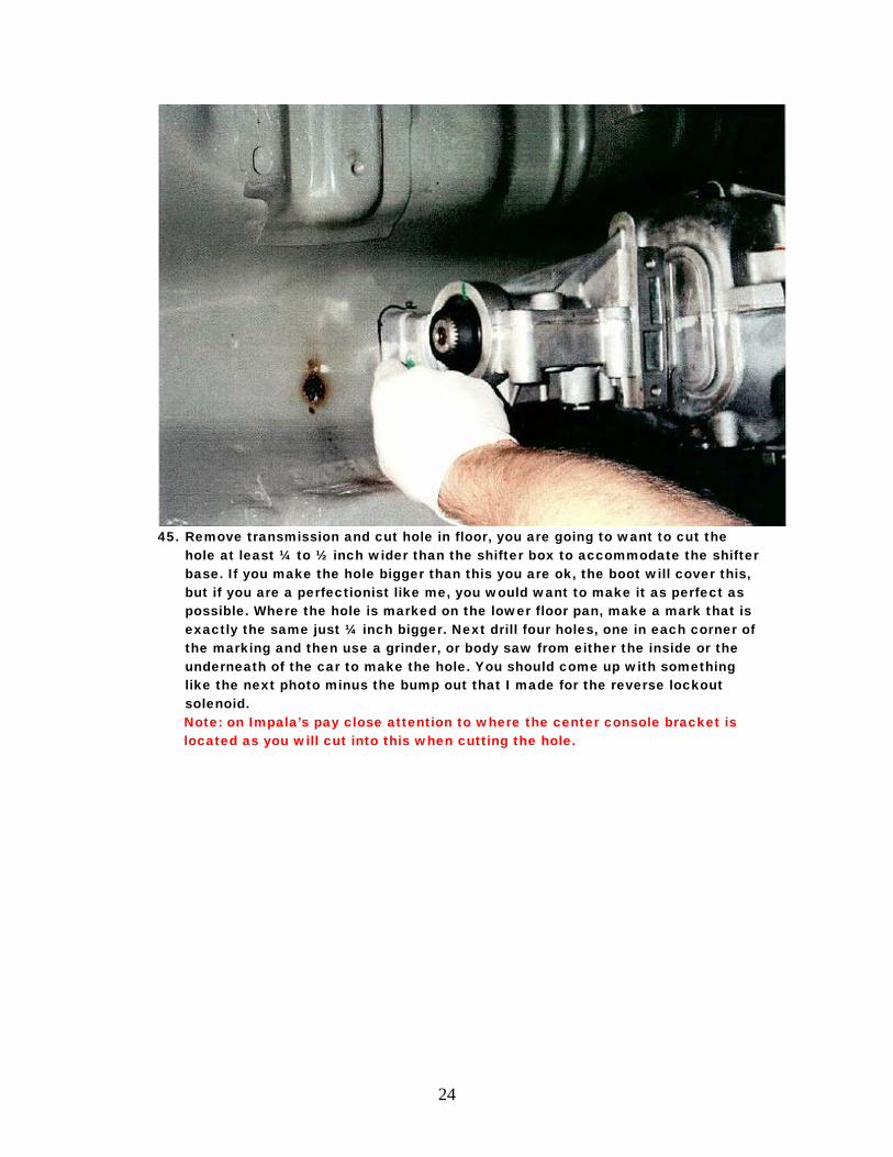
45. Remove transmission and cut hole in floor, you are going to want to cut the
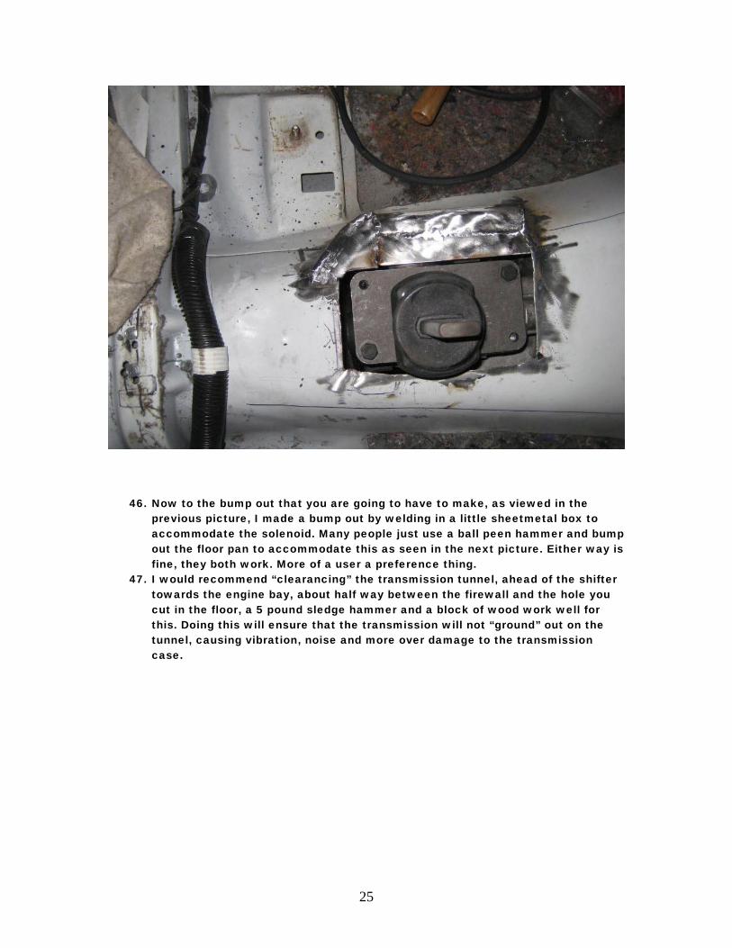
hole at least ¼ to ½ inch wider than the shifter box to accommodate the shifter base. If you make the hole bigger than this you are ok, the boot will cover this, but if you are a perfectionist like me, you would want to make it as perfect as possible. Where the hole is marked on the lower floor pan, make a mark that is exactly the same just ¼ inch bigger. Next drill four holes, one in each corner of the marking and then use a grinder, or body saw from either the inside or the underneath of the car to make the hole. You should come up with something like the next photo minus the bump out that I made for the reverse lockout solenoid. Note: on Impala’s pay close attention to where the center console bracket is located as you will cut into this when cutting the hole.
25
46. Now to the bump out that you are going to have to make, as viewed in the
previous picture, I made a bump out by welding in a little sheetmetal box to accommodate the solenoid. Many people just use a ball peen hammer and bump out the floor pan to accommodate this as seen in the next picture. Either way is fine, they both work. More of a user a preference thing.
47. I would recommend “clearancing” the transmission tunnel, ahead of the shifter towards the engine bay, about half way between the firewall and the hole you cut in the floor, a 5 pound sledge hammer and a block of wood work well for this. Doing this will ensure that the transmission will not “ground” out on the tunnel, causing vibration, noise and more over damage to the transmission case.
26
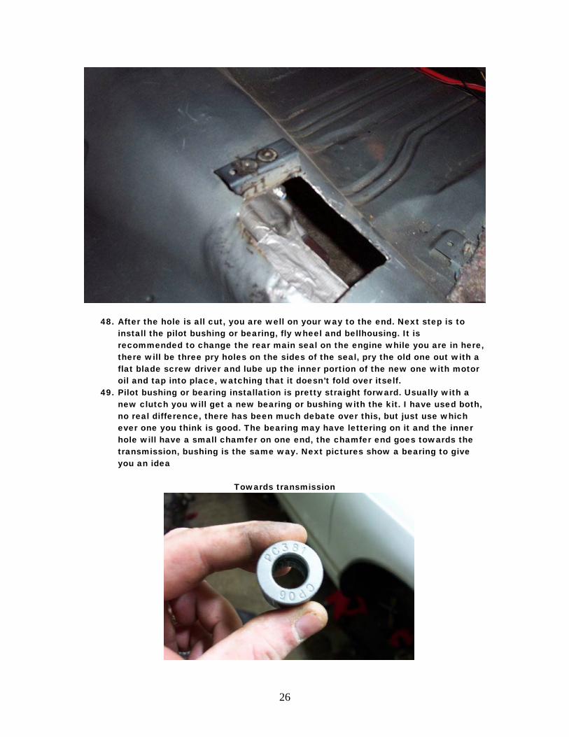
48. After the hole is all cut, you are well on your way to the end. Next step is to install the pilot bushing or bearing, fly wheel and bellhousing. It is recommended to change the rear main seal on the engine while you are in here, there will be three pry holes on the sides of the seal, pry the old one out with a flat blade screw driver and lube up the inner portion of the new one with motor oil and tap into place, watching that it doesn’t fold over itself.
49. Pilot bushing or bearing installation is pretty straight forward. Usually with a new clutch you will get a new bearing or bushing with the kit. I have used both, no real difference, there has been much debate over this, but just use which ever one you think is good. The bearing may have lettering on it and the inner hole will have a small chamfer on one end, the chamfer end goes towards the transmission, bushing is the same way. Next pictures show a bearing to give you an idea
Towards transmission
27
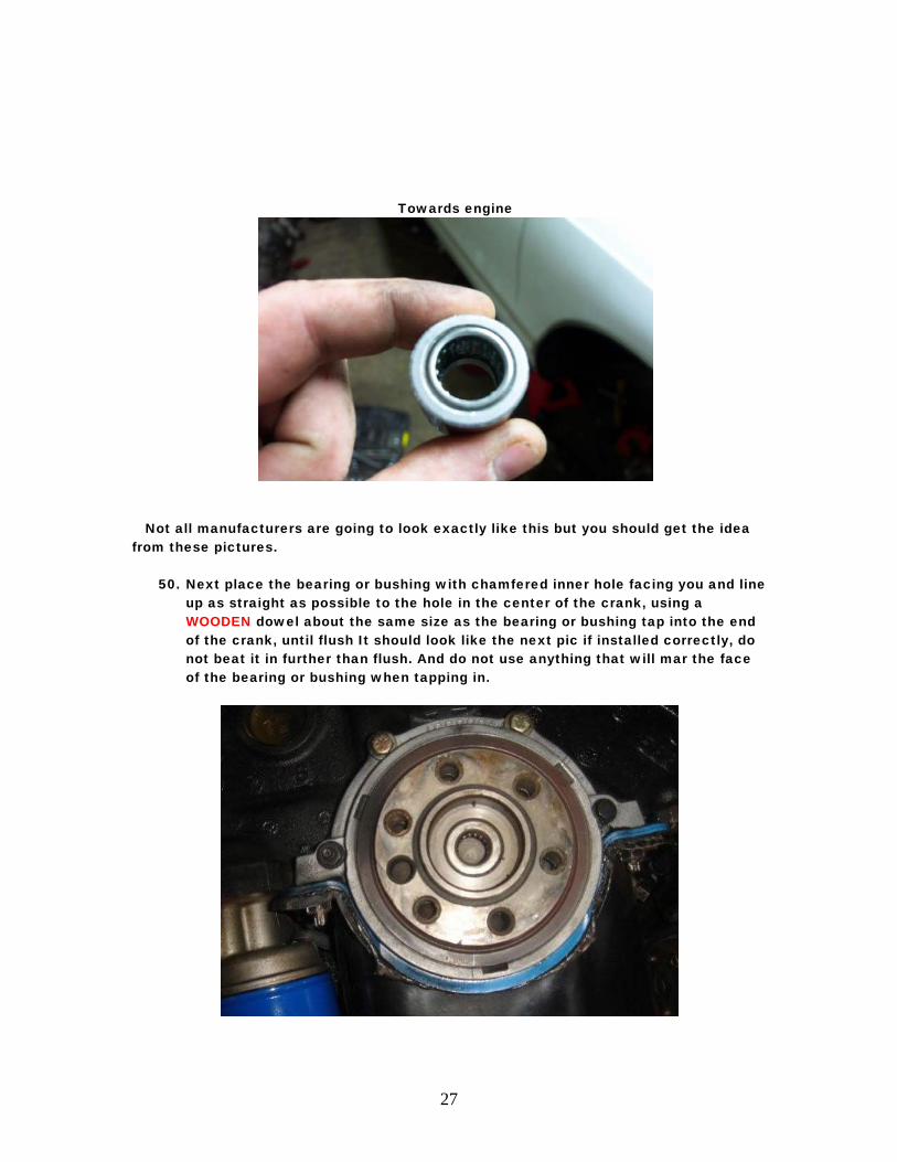
Towards engine
Not all manufacturers are going to look exactly like this but you should get the idea from these pictures.
50. Next place the bearing or bushing with chamfered inner hole facing you and line
up as straight as possible to the hole in the center of the crank, using a WOODEN dowel about the same size as the bearing or bushing tap into the end of the crank, until flush It should look like the next pic if installed correctly, do not beat it in further than flush. And do not use anything that will mar the face of the bearing or bushing when tapping in.
28
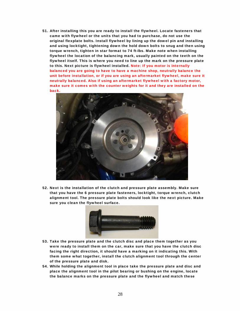
51. After installing this you are ready to install the flywheel. Locate fasteners that came with flywheel or the units that you had to purchase, do not use the original flexplate bolts. Install flywheel by lining up the dowel pin and installing and using locktight, tightening down the hold down bolts to snug and then using torque wrench, tighten in star format to 74 ft-lbs. Make note when installing flywheel the location of the balancing mark, usually painted on the teeth on the flywheel itself. This is where you need to line up the mark on the pressure plate to this. Next picture is flywheel installed. Note: If you motor is internally balanced you are going to have to have a machine shop, neutrally balance the unit before installation, or if you are using an aftermarket flywheel, make sure it neutrally balanced. Also if using an aftermarket flywheel with a factory motor, make sure it comes with the counter weights for it and they are installed on the back.
52. Next is the installation of the clutch and pressure plate assembly. Make sure that you have the 6 pressure plate fasteners, locktight, torque wrench, clutch alignment tool. The pressure plate bolts should look like the next picture. Make sure you clean the flywheel surface.
53. Take the pressure plate and the clutch disc and place them together as you
were ready to install them on the car, make sure that you have the clutch disc facing the right direction, it should have a marking on it indicating this. With them some what together, install the clutch alignment tool through the center of the pressure plate and disk.
54. While holding the alignment tool in place take the pressure plate and disc and place the alignment tool in the pilot bearing or bushing on the engine, locate the balance marks on the pressure plate and the flywheel and match these
29
marks up. (Note: most times balance marks are evident on the flywheel or pressure plate, this isn’t a big deal, you shouldn’t have any issues with installing it whichever way it comes out.
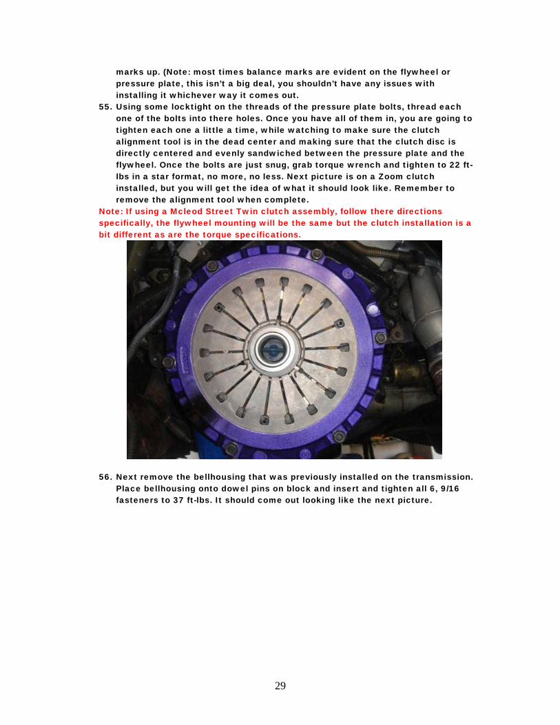
55. Using some locktight on the threads of the pressure plate bolts, thread each one of the bolts into there holes. Once you have all of them in, you are going to tighten each one a little a time, while watching to make sure the clutch alignment tool is in the dead center and making sure that the clutch disc is directly centered and evenly sandwiched between the pressure plate and the flywheel. Once the bolts are just snug, grab torque wrench and tighten to 22 ft-lbs in a star format, no more, no less. Next picture is on a Zoom clutch installed, but you will get the idea of what it should look like. Remember to remove the alignment tool when complete.
Note: If using a Mcleod Street Twin clutch assembly, follow there directions specifically, the flywheel mounting will be the same but the clutch installation is a bit different as are the torque specifications.
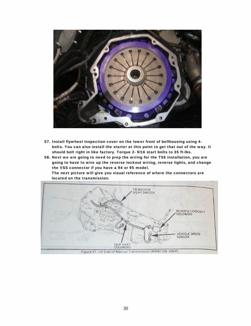
56. Next remove the bellhousing that was previously installed on the transmission. Place bellhousing onto dowel pins on block and insert and tighten all 6, 9/16 fasteners to 37 ft-lbs. It should come out looking like the next picture.
30
57. Install flywheel inspection cover on the lower front of bellhousing using 4- bolts. You can also install the starter at this point to get that out of the way. It should bolt right in like factory. Torque 2- 9/16 start bolts to 35 ft-lbs.
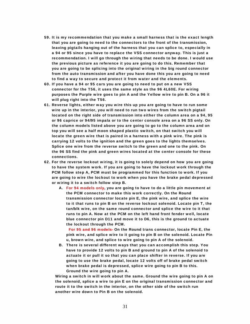
58. Next we are going to need to prep the wiring for the T56 installation, you are going to have to wire up the reverse lockout wiring, reverse lights, and change the VSS connector if you have a 94 or 95 model. The next picture will give you visual reference of where the connectors are located on the transmission.
31
59. It is my recommendation that you make a small harness that is the exact length
that you are going to need to the connectors to the front of the transmission, leaving pigtails hanging out of the harness that you can splice to, especially in a 94 or 95 since you have to replace the VSS connector anyway. This is just a recommendation. I will go through the wiring that needs to be done. I would use the previous picture as reference it you are going to do this. Remember that you are going to be splicing into the original wiring in the big round connector from the auto transmission and after you have done this you are going to need to find a way to secure and protect it from water and the elements.
60. If you have a 94 or 95 cars you are going to need to put on a new VSS connector for the T56, it uses the same style as the 96 4L60E. For wiring purposes the Purple wire goes to pin A and the Yellow wire to pin B. On a 96 it will plug right into the T56.
61. Reverse lights, either way you wire this up you are going to have to run some wire up in the interior, you will need to run two wires from the switch pigtail located on the right side of transmission into either the column area on a 94, 95 or 96 caprice or 94/95 impala or to the center console area on a 96 SS only. On the column models listed above you are going to go to the column area and on top you will see a half moon shaped plastic switch, on that switch you will locate the green wire that is paired in a harness with a pink wire. The pink is carrying 12 volts to the ignition and the green goes to the lights themselves. Splice one wire from the reverse switch to the green and one to the pink. On the 96 SS find the pink and green wires located at the center console for these connections.
62. For the reverse lockout wiring, it is going to solely depend on how you are going to have the system work. If you are going to have the lockout work through the PCM follow step A, PCM must be programmed for this function to work. If you are going to wire the lockout to work when you have the brake pedal depressed or wiring it to a switch follow step B.
A. For 94 models only, you are going to have to do a little pin movement at the PCM connector to make this work correctly. On the Round transmission connector locate pin E, the pink wire, and splice the wire to it that runs to pin B on the reverse lockout solenoid. Locate pin T, the tan/blk wire, on the same round connector and splice the wire to it that runs to pin A. Now at the PCM on the left hand front fender well, locate blue connector pin D11 and move it to D6, this is the ground to actuate the lockout through the PCM.
For 95 and 96 models- On the Round trans connector, locate Pin E, the pink wire, and splice wire to it going to pin B on the solenoid. Locate Pin u, brown wire, and splice to wire going to pin A of the solenoid.
B. There is several different ways that you can accomplish this step. You have to provide 12 volts to pin B and ground to pin A of the solenoid to actuate it or pull it so that you can place shifter in reverse. If you are going to use the brake pedal, locate 12 volts off of brake pedal switch when brake pedal is depressed, splice wire going to pin B to this. Ground the wire going to pin A.
Wiring a switch in will work about the same. Ground the wire going to pin A on the solenoid, splice a wire to pin E on the original transmission connector and route it to the switch in the interior, on the other side of the switch run another wire down to Pin B on the solenoid.
32
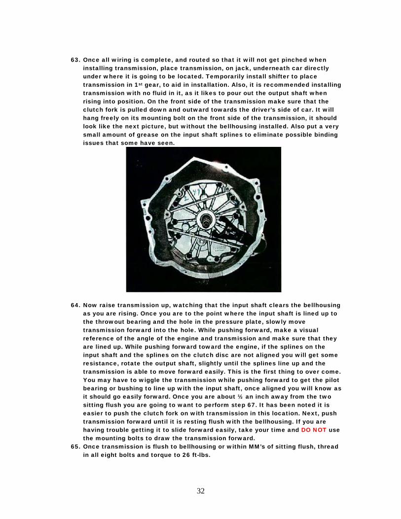
63. Once all wiring is complete, and routed so that it will not get pinched when
installing transmission, place transmission, on jack, underneath car directly under where it is going to be located. Temporarily install shifter to place transmission in 1st gear, to aid in installation. Also, it is recommended installing transmission with no fluid in it, as it likes to pour out the output shaft when rising into position. On the front side of the transmission make sure that the clutch fork is pulled down and outward towards the driver’s side of car. It will hang freely on its mounting bolt on the front side of the transmission, it should look like the next picture, but without the bellhousing installed. Also put a very small amount of grease on the input shaft splines to eliminate possible binding issues that some have seen.
64. Now raise transmission up, watching that the input shaft clears the bellhousing as you are rising. Once you are to the point where the input shaft is lined up to the throwout bearing and the hole in the pressure plate, slowly move transmission forward into the hole. While pushing forward, make a visual reference of the angle of the engine and transmission and make sure that they are lined up. While pushing forward toward the engine, if the splines on the input shaft and the splines on the clutch disc are not aligned you will get some resistance, rotate the output shaft, slightly until the splines line up and the transmission is able to move forward easily. This is the first thing to over come. You may have to wiggle the transmission while pushing forward to get the pilot bearing or bushing to line up with the input shaft, once aligned you will know as it should go easily forward. Once you are about ½ an inch away from the two sitting flush you are going to want to perform step 67. It has been noted it is easier to push the clutch fork on with transmission in this location. Next, push transmission forward until it is resting flush with the bellhousing. If you are having trouble getting it to slide forward easily, take your time and DO NOT use the mounting bolts to draw the transmission forward.
65. Once transmission is flush to bellhousing or within MM’s of sitting flush, thread in all eight bolts and torque to 26 ft-lbs.
33
66. Now route in the wiring that you have completed in previous steps and plug in connectors. Bag the original transmission connector and secure in a place to keep it as dry as possible.
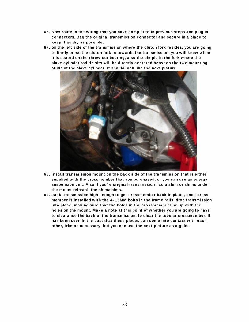
67. on the left side of the transmission where the clutch fork resides, you are going to firmly press the clutch fork in towards the transmission, you will know when it is seated on the throw out bearing, also the dimple in the fork where the slave cylinder rod tip sits will be directly centered between the two mounting studs of the slave cylinder. It should look like the next picture
68. Install transmission mount on the back side of the transmission that is either
supplied with the crossmember that you purchased, or you can use an energy suspension unit. Also if you’re original transmission had a shim or shims under the mount reinstall the shim/shims.
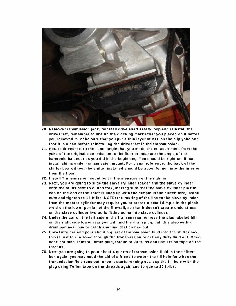
69. Jack transmission high enough to get crossmember back in place, once cross member is installed with the 4- 15MM bolts in the frame rails, drop transmission into place, making sure that the holes in the crossmember line up with the holes on the mount. Make a note at this point of whether you are going to have to clearance the back of the transmission, to clear the tubular crossmember. It has been seen in the past that these pieces can come into contact with each other, trim as necessary, but you can use the next picture as a guide
34
70. Remove transmission jack, reinstall drive shaft safety loop and reinstall the
driveshaft, remember to line up the clocking marks that you placed on it before you removed it. Make sure that you put a thin layer of ATF on the slip yoke and that it is clean before reinstalling the driveshaft in the transmission.
71. Rotate driveshaft to the same angle that you made the measurement from the yoke of the original transmission to the floor or measure the angle of the harmonic balancer as you did in the beginning. You should be right on, if not, install shims under transmission mount. For visual reference, the back of the shifter box without the shifter installed should be about ½ inch into the interior from the floor.
72. Install Transmission mount bolt if the measurement is right on. 73. Next, you are going to slide the slave cylinder spacer and the slave cylinder
onto the studs next to clutch fork, making sure that the slave cylinder plastic cap on the end of the shaft is lined up with the dimple in the clutch fork, install nuts and tighten to 15 ft-lbs. NOTE: the routing of the line to the slave cylinder from the master cylinder may require you to create a small dimple in the pinch weld on the lower portion of the firewall, so that it doesn’t create undo stress on the slave cylinder hydraulic fitting going into slave cylinder.
74. Under the car on the left side of the transmission remove the plug labeled fill, on the right side lower rear you will find the drain plug, pull this also with a drain pan near buy to catch any fluid that comes out.
75. Crawl into car and pour about a quart of transmission fluid into the shifter box, this is just to run some through the transmission to get any dirty fluid out. Once done draining, reinstall drain plug, torque to 20 ft-lbs and use Teflon tape on the threads.
76. Next you are going to pour about 4 quarts of transmission fluid in the shifter box again, you may need the aid of a friend to watch the fill hole for when the transmission fluid runs out, once it starts running out, cap the fill hole with the plug using Teflon tape on the threads again and torque to 20 ft-lbs.

35
77. Next install shifter onto shifter box using silicone around the rim of the box, making sure to line up the ball of the shift lever to the socket on the shift linkage. Tighten 4- bolts.
78. Reinstall exhaust to the ball and socket flanges on either side of the transmission.
79. Now you are going to have to check clutch disengagement. Place transmission in 2nd gear and push in clutch, have a friend rotate the rear wheels, they should turn freely. Releasing of the clutch will cause the wheels not to turn. If they do as described above, you have success and the car is ready to start.
80. Here comes the fun part. Reconnect the battery. Start car with transmission in neutral. The rear wheels should not be turning. Push in clutch and shift through the gears making sure that it shifts smoothly. Place in first gear and release clutch you should have wheel movement. Push clutch and wheels should stop.
81. Check for leaks and listen for any noises. Note: When in neutral the T56 is known for sounding like a can of marbles, this is normal.
82. Now on the inside you are going to put on the shift boot, to do this, with shift ball removed, slide boot over shift handle and slide down to floor. The shift boot has a moldable metal ring in the base. Start in one corner fastening down with short screws and mold it as you go. From underneath you are going to want to check after every screw to make sure that they aren’t going to make contact. After boot is installed, install shifter relocation bracket onto shifter stub coming out of boot and install shifter lever. Next pictures will give you reference of what it should look like. The first is of the boot installed and without the relocation bracket installed, the next is of the bracket installed
Note: Shifter handle can be orientated on either the driver’s or passengers side of shifter stub coming through boot. It has been seen, especially on SS models with the center console that it needs to be located on the passenger side.
36
83. Double check all connections under vehicle. After this is complete lower car. 84. Now you need to reinstall the carpet over the shifter, you are going to have to
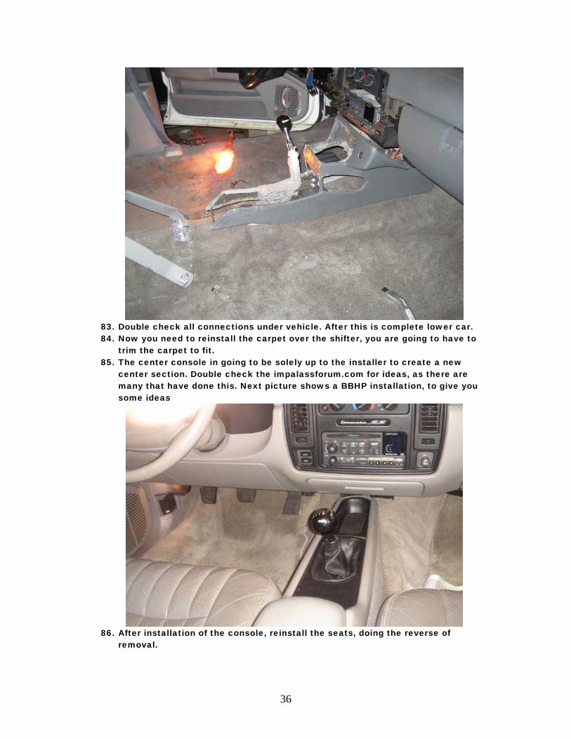
trim the carpet to fit. 85. The center console in going to be solely up to the installer to create a new
center section. Double check the impalassforum.com for ideas, as there are many that have done this. Next picture shows a BBHP installation, to give you some ideas
86. After installation of the console, reinstall the seats, doing the reverse of
removal.
37
87. The last step is to have you PCM programmed for the T56 installation. The only thing that I can recommend is using someone that has experience making changes to the PCM for this installation. PCMPerformance.com is one that I would recommend for this. Also if you wired the reverse lockout to work through the PCM it is going to have to have and F-Body base code “tweaked” to work in a B-Body car. I hope this guide has helped you through this. I have tried to document everything that I have learned along the way as well as others. Good luck with the install. Oh one final note, you may need to replace your rear tires more often.
38
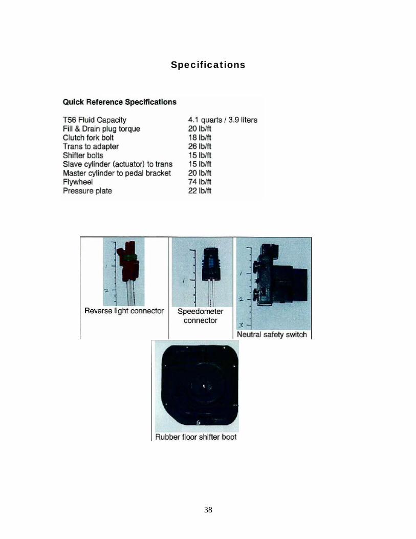
Specifications
39
Special Thanks
A special thanks needs to go out to the forum members @ imapalassforum.com. These guys are a great bunch of individuals and are willing to help in any situation. Thanks to Roger ( Ball ss) Noel (Got “CUPCAKE” Bearings) Todd (GreenHornet) Gerry (95Wagon) Sean (Ark SS) Sslumpin Imp Sharkx And others, that I am sure that I forgot to mention.
40
USING ORIGINAL TRANSMISSION COOLER AS A POWER STEERING COOLER
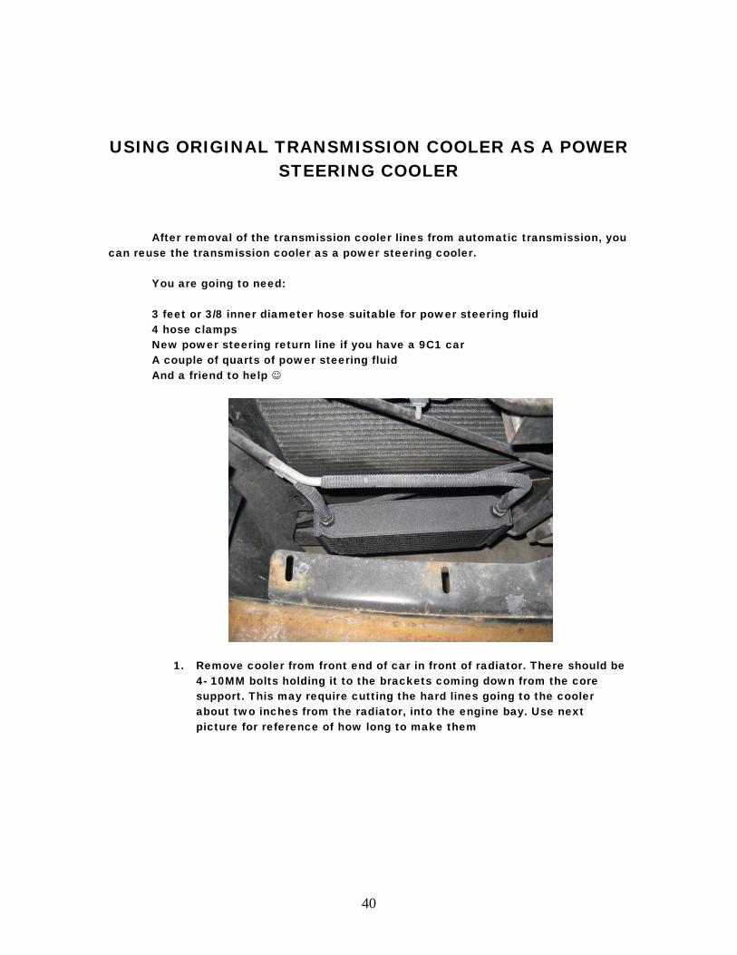
After removal of the transmission cooler lines from automatic transmission, you can reuse the transmission cooler as a power steering cooler.
You are going to need: 3 feet or 3/8 inner diameter hose suitable for power steering fluid 4 hose clamps New power steering return line if you have a 9C1 car A couple of quarts of power steering fluid And a friend to help
1. Remove cooler from front end of car in front of radiator. There should be 4- 10MM bolts holding it to the brackets coming down from the core support. This may require cutting the hard lines going to the cooler about two inches from the radiator, into the engine bay. Use next picture for reference of how long to make them
41
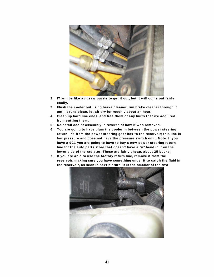
2. IT will be like a jigsaw puzzle to get it out, but it will come out fairly
easily. 3. Flush the cooler out using brake cleaner, run brake cleaner through it
until it runs clean, let air dry for roughly about an hour. 4. Clean up hard line ends, and free them of any burrs that we acquired
from cutting them. 5. Reinstall cooler assembly in reverse of how it was removed. 6. You are going to have plum the cooler in between the power steering
return line from the power steering gear box to the reservoir; this line is low pressure and does not have the pressure switch on it. Note: If you have a 9C1 you are going to have to buy a new power steering return line for the auto parts store that doesn’t have a “u” bend in it on the lower side of the radiator. These are fairly cheap, about 25 bucks.
7. If you are able to use the factory return line, remove it from the reservoir, making sure you have something under it to catch the fluid in the reservoir, as seen in next picture, it is the smaller of the two
42
8. If you are using a new line, remove line from steering gear box and let drain, after fluid is gone, remove old line and install new line that will be routed next to forward crossmember.
9. Route the rubber line that used to go to the reservoir to the lower hard line on the cooler assembly, push line onto hard line enough so that you can install two hose clamps on it to secure it to the tube, as seen in the second picture.
10. This is where you are going to need some 3/8 inner diameter hose from the parts store, measure and cut a piece that will be long enough to go from cooler to power steering reservoir.
11. Attach line using same hose clamp method described above at the cooler side and reuse the original clamp at the reservoir.
12. Fill power steering reservoir until it indicates full cold. Note: it is going to take more fluid as you are filling the reservoir also.
13. Now jack the front end of your car and support on jack stands. 14. You are going to need a friend to help you with this next procedure. 15. with one of you inside the car and the steering wheel unlocked, with the
car off turn the steering wheel lock to lock at least 40 or 50 times and have your friend watch the reservoir to make sure that it stays at the same level, add fluid as needed. When there is no presence of air bubbles coming back into reservoir, you should be good.
16. Start car and make sure you have no leaks. 17. And that is it; you now have a cooler running power steering system.
43
Impala SS and Caprice T56 Six Speed install guide Supplement A
This is an alternate method for the hole in the transmission tunnel and some different steps to take if the catalytic converter hits.
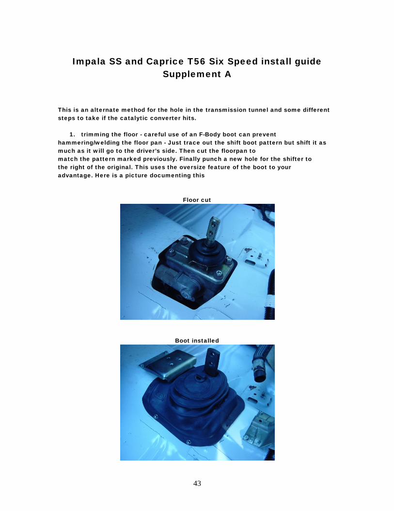
1. trimming the floor - careful use of an F-Body boot can prevent hammering/welding the floor pan - Just trace out the shift boot pattern but shift it as much as it will go to the driver’s side. Then cut the floorpan to match the pattern marked previously. Finally punch a new hole for the shifter to the right of the original. This uses the oversize feature of the boot to your advantage. Here is a picture documenting this
Floor cut
Boot installed
44
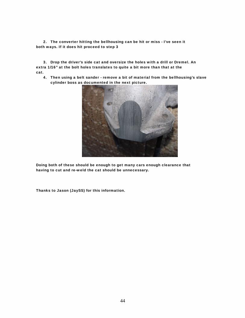
2. The converter hitting the bellhousing can be hit or miss - I’ve seen it both ways. If it does hit proceed to step 3
3. Drop the driver’s side cat and oversize the holes with a drill or Dremel. An extra 1/16” at the bolt holes translates to quite a bit more than that at the cat.
4. Then using a belt sander - remove a bit of material from the bellhousing’s slave cylinder boss as documented in the next picture.
Doing both of these should be enough to get many cars enough clearance that having to cut and re-weld the cat should be unnecessary. Thanks to Jason (JaySS) for this information.
45
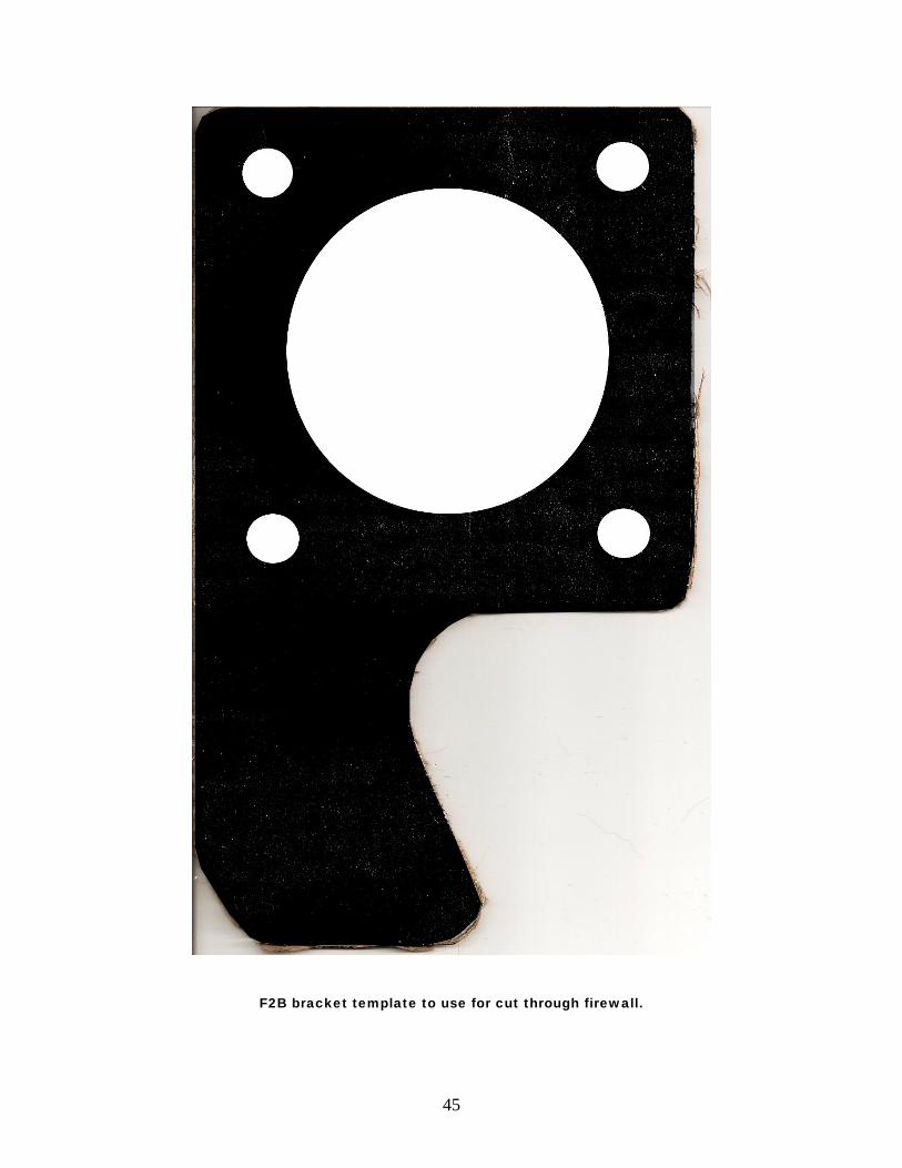
F2B bracket template to use for cut through firewall.
46
Impala SS and Caprice Cruise Clutch and Brake Release Information
By: Mike Fetcko
Below you will find information for the above topic with diagrams to aid in a factory style installation of the cruise anticipate logic, so that it works as designed in the Fbody cars.
47
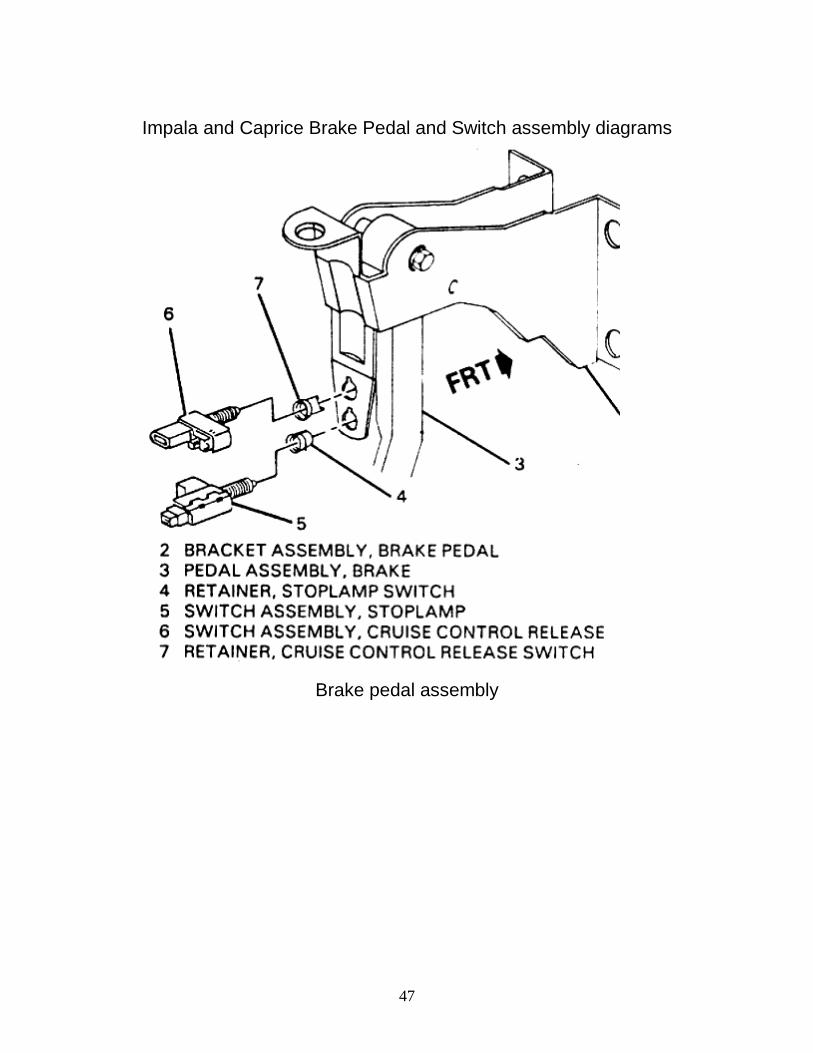
Impala and Caprice Brake Pedal and Switch assembly diagrams
Brake pedal assembly
48
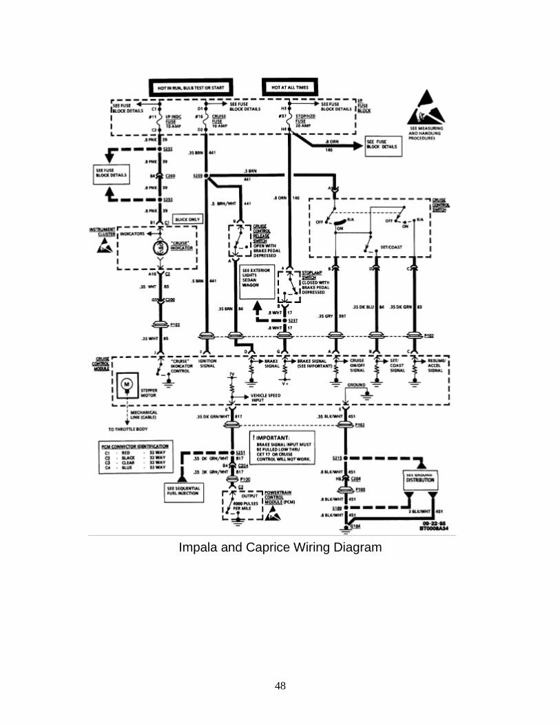
Impala and Caprice Wiring Diagram
49
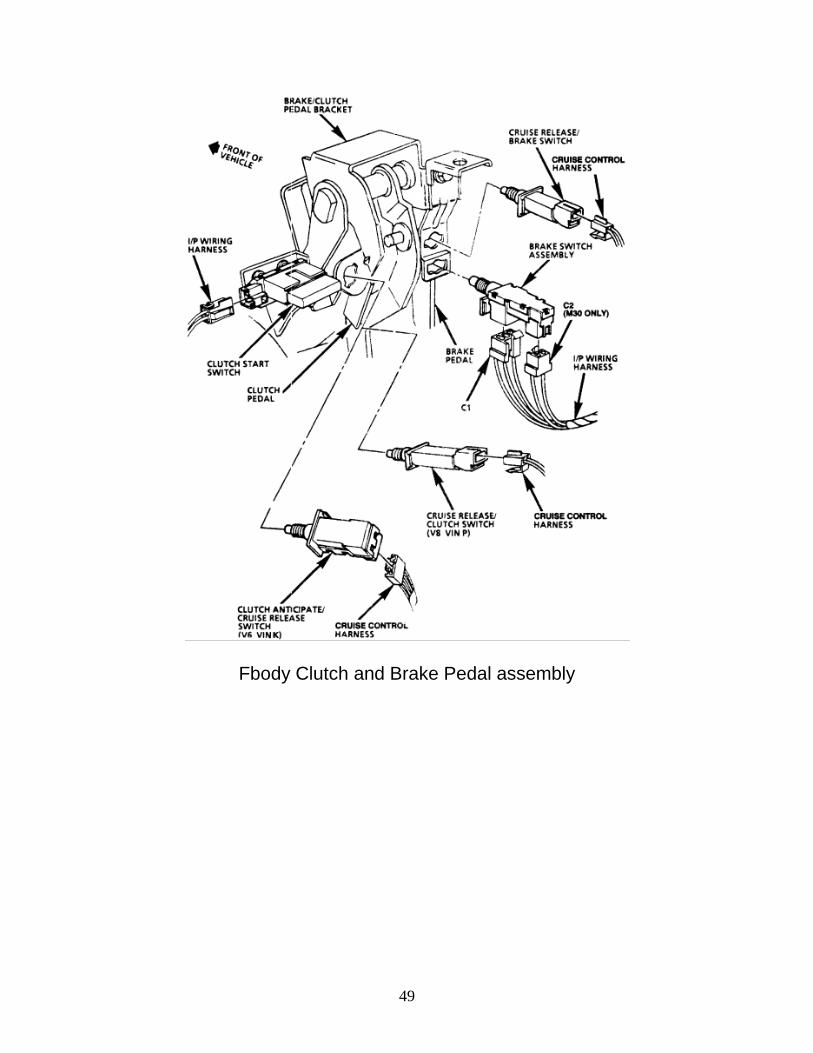
Fbody Clutch and Brake Pedal assembly
50
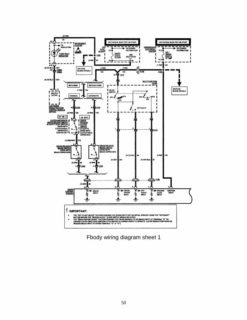
Fbody wiring diagram sheet 1
51
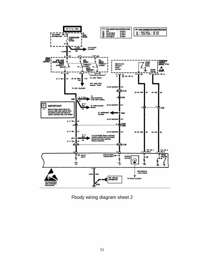
Fbody wiring diagram sheet 2
52
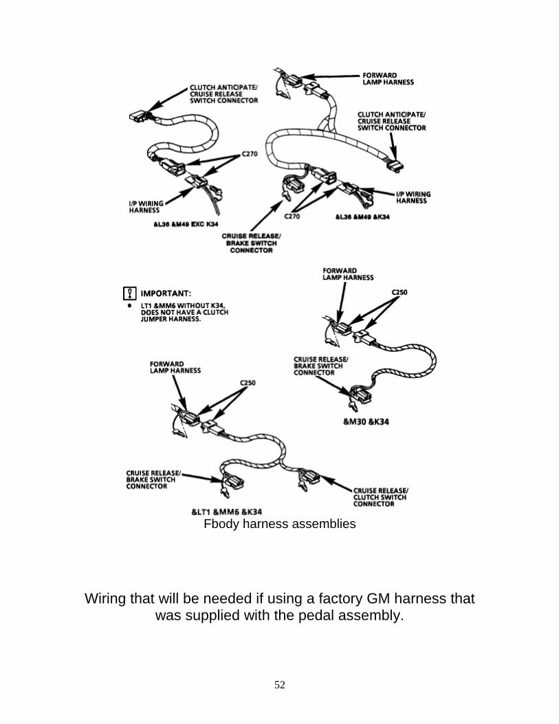
Fbody harness assemblies
Wiring that will be needed if using a factory GM harness that was supplied with the pedal assembly.
53
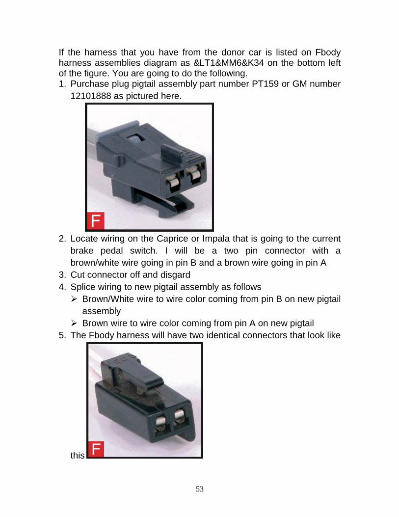
If the harness that you have from the donor car is listed on Fbody harness assemblies diagram as <1&MM6&K34 on the bottom left of the figure. You are going to do the following. 1. Purchase plug pigtail assembly part number PT159 or GM number
12101888 as pictured here.
2. Locate wiring on the Caprice or Impala that is going to the current
brake pedal switch. I will be a two pin connector with a brown/white wire going in pin B and a brown wire going in pin A
3. Cut connector off and disgard 4. Splice wiring to new pigtail assembly as follows Brown/White wire to wire color coming from pin B on new pigtail
assembly Brown wire to wire color coming from pin A on new pigtail
5. The Fbody harness will have two identical connectors that look like
this
54
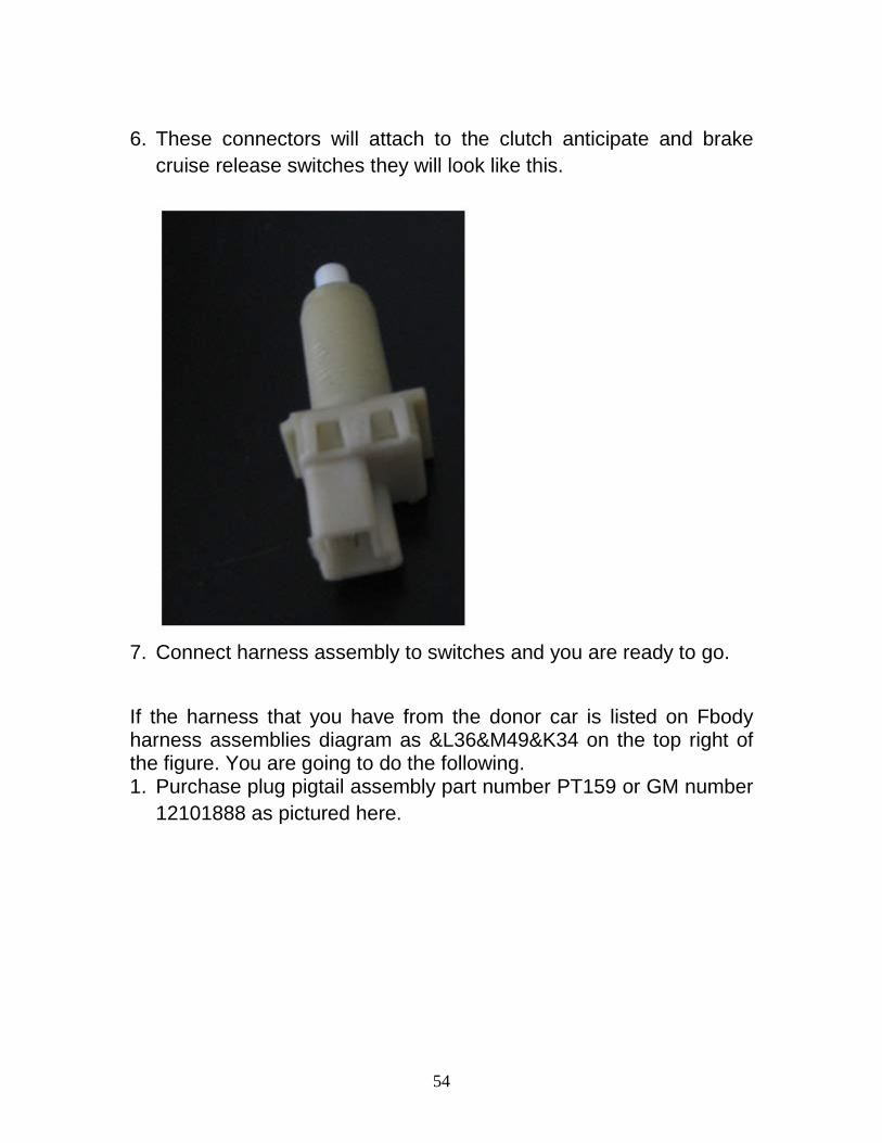
6. These connectors will attach to the clutch anticipate and brake
cruise release switches they will look like this.
7. Connect harness assembly to switches and you are ready to go.
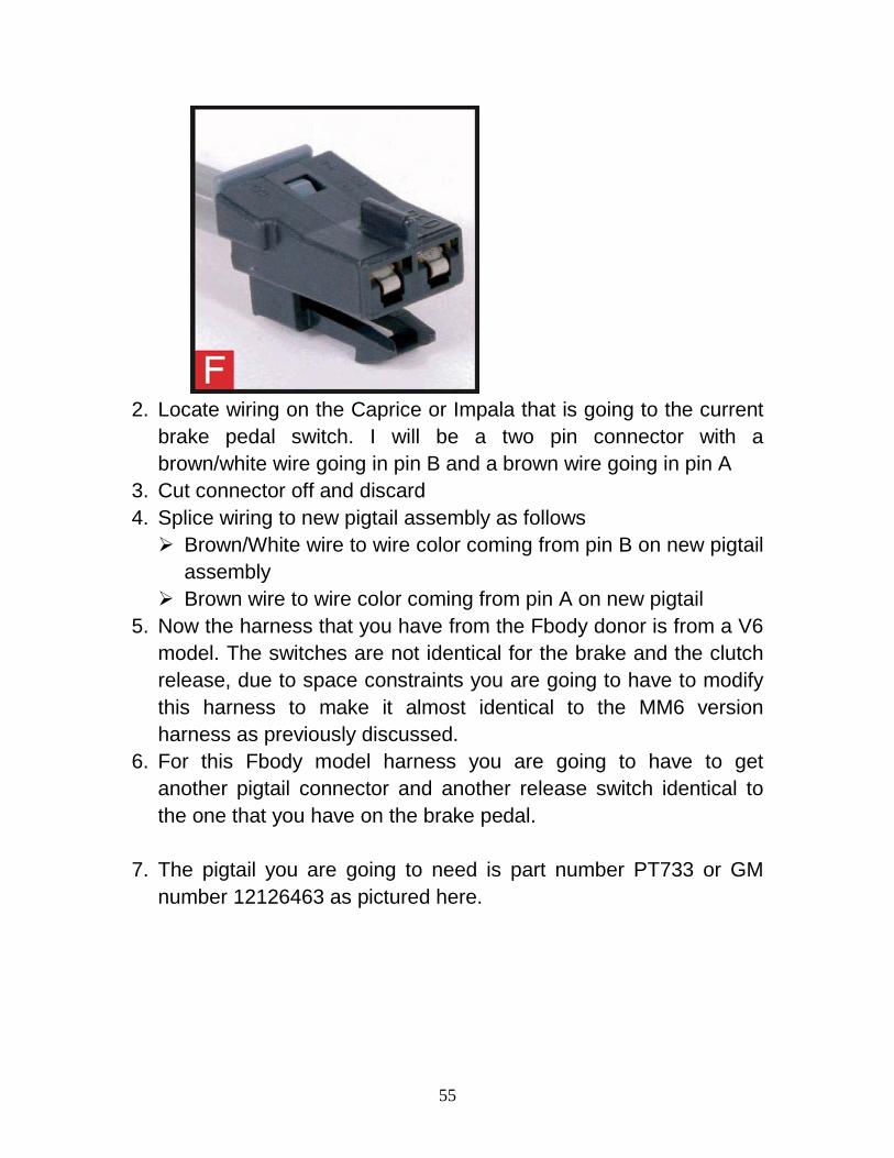
If the harness that you have from the donor car is listed on Fbody harness assemblies diagram as &L36&M49&K34 on the top right of the figure. You are going to do the following. 1. Purchase plug pigtail assembly part number PT159 or GM number
12101888 as pictured here.
55
2. Locate wiring on the Caprice or Impala that is going to the current
brake pedal switch. I will be a two pin connector with a brown/white wire going in pin B and a brown wire going in pin A
3. Cut connector off and discard 4. Splice wiring to new pigtail assembly as follows Brown/White wire to wire color coming from pin B on new pigtail
assembly Brown wire to wire color coming from pin A on new pigtail
5. Now the harness that you have from the Fbody donor is from a V6 model. The switches are not identical for the brake and the clutch release, due to space constraints you are going to have to modify this harness to make it almost identical to the MM6 version harness as previously discussed.
6. For this Fbody model harness you are going to have to get another pigtail connector and another release switch identical to the one that you have on the brake pedal.
7. The pigtail you are going to need is part number PT733 or GM number 12126463 as pictured here.
56
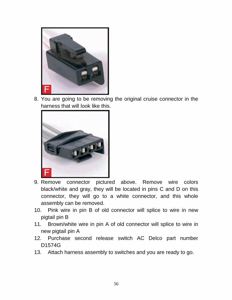
8. You are going to be removing the original cruise connector in the
harness that will look like this.
9. Remove connector pictured above. Remove wire colors
black/white and gray, they will be located in pins C and D on this connector, they will go to a white connector, and this whole assembly can be removed.
10. Pink wire in pin B of old connector will splice to wire in new pigtail pin B
11. Brown/white wire in pin A of old connector will splice to wire in new pigtail pin A
12. Purchase second release switch AC Delco part number D1574G
13. Attach harness assembly to switches and you are ready to go.
57
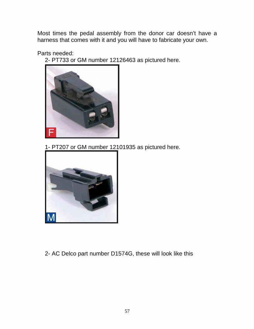
Most times the pedal assembly from the donor car doesn’t have a harness that comes with it and you will have to fabricate your own. Parts needed:
2- PT733 or GM number 12126463 as pictured here.
1- PT207 or GM number 12101935 as pictured here.
2- AC Delco part number D1574G, these will look like this
58
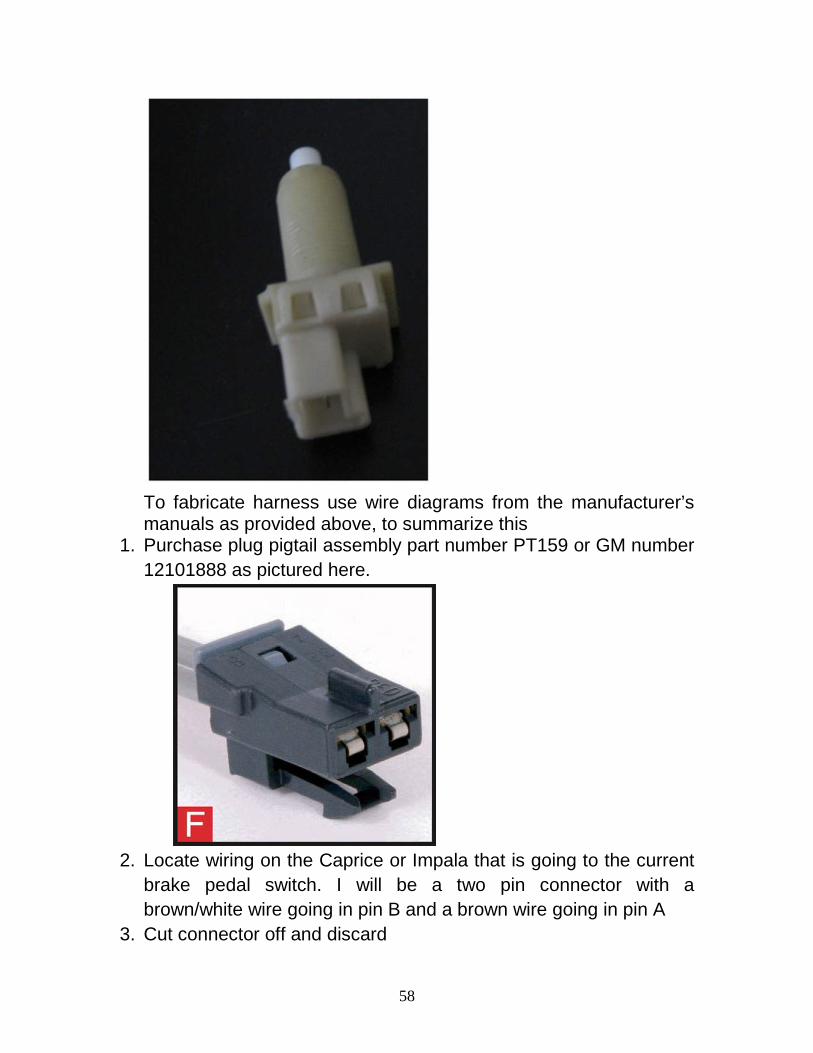
To fabricate harness use wire diagrams from the manufacturer’s manuals as provided above, to summarize this
1. Purchase plug pigtail assembly part number PT159 or GM number 12101888 as pictured here.
2. Locate wiring on the Caprice or Impala that is going to the current
brake pedal switch. I will be a two pin connector with a brown/white wire going in pin B and a brown wire going in pin A
3. Cut connector off and discard
59
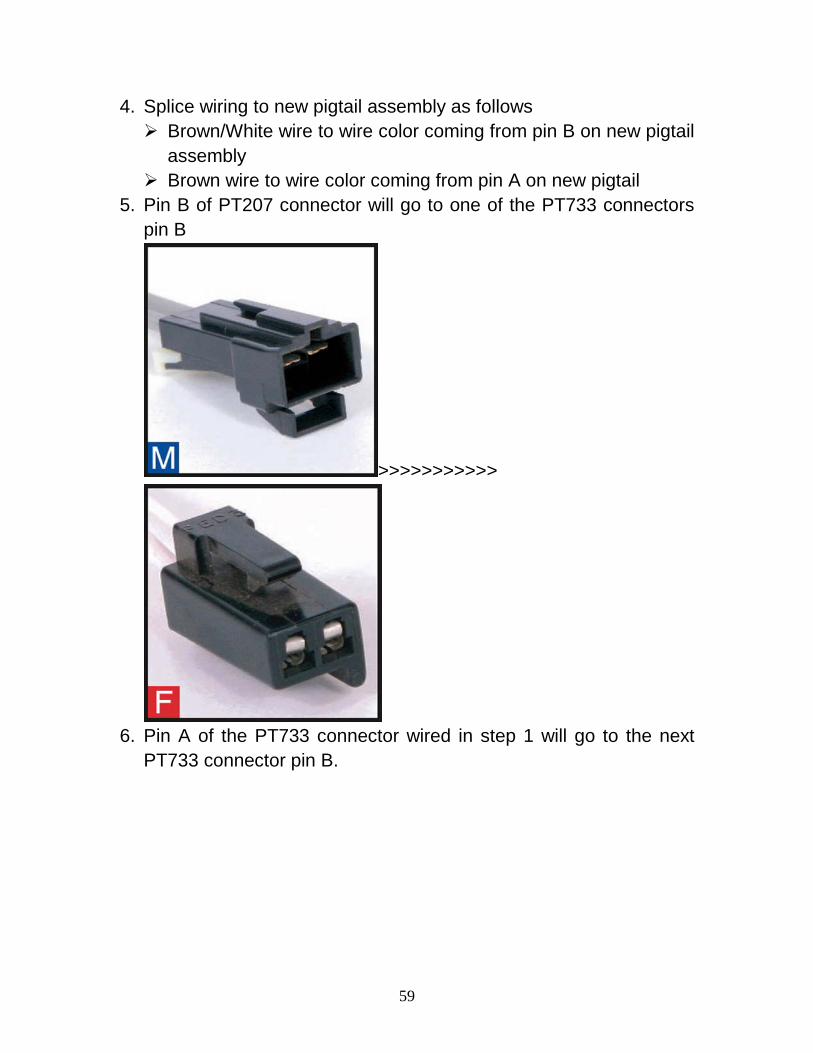
4. Splice wiring to new pigtail assembly as follows Brown/White wire to wire color coming from pin B on new pigtail
assembly Brown wire to wire color coming from pin A on new pigtail
5. Pin B of PT207 connector will go to one of the PT733 connectors pin B
>>>>>>>>>>>
6. Pin A of the PT733 connector wired in step 1 will go to the next
PT733 connector pin B.
60
>>>>>>>>>>>
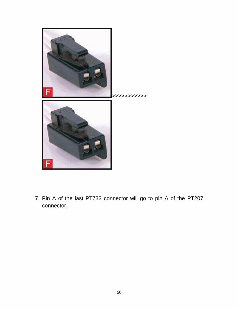
7. Pin A of the last PT733 connector will go to pin A of the PT207
connector.
61
>>>>>>>>>>>
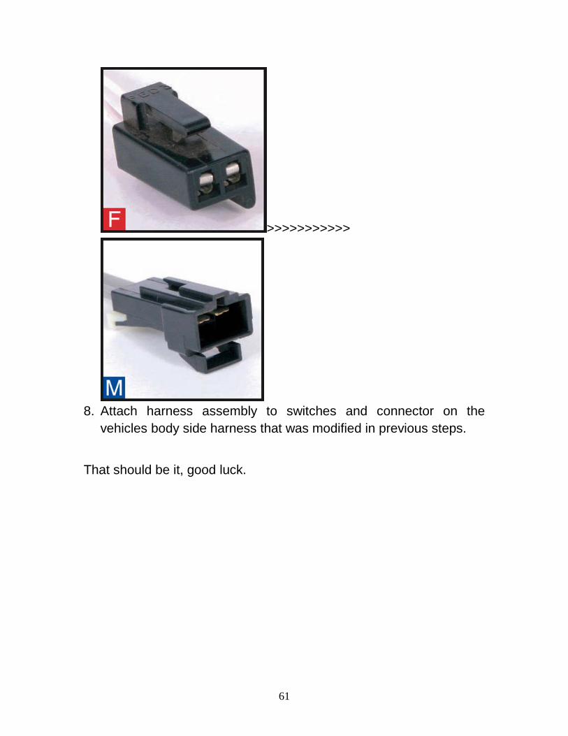
8. Attach harness assembly to switches and connector on the
vehicles body side harness that was modified in previous steps.
That should be it, good luck.


