3 Operating Instructions 42 3.1 Precautions when first using the device............................................42 3.2 Checking the Battery Level ....................................................................43 3.3 Powering up the Impedo Duo ...............................................................44 3.4 Impedo Duo Unlock Screen ...................................................................45 3.5 Shutting down ...........................................................................................46 3.6 Power Cycling with the Reset Switch ..................................................47
Impedo DUO User Guide 4
4 OLED Information Display 48 4.1 Meter points ..............................................................................................48 4.2 Serial Number ...........................................................................................49 4.3 IP Address ..................................................................................................49 4.4 Firmware Version ....................................................................................49 4.5 Temperature .............................................................................................49 4.6 Battery Status............................................................................................49 4.7 On-Board Storage Usage ........................................................................50 4.8 Time source ...............................................................................................50 4.9 Connection to server ...............................................................................51 4.10 Ethernet connectivity .............................................................................51 4.11 Time of Day and Date ..............................................................................51 4.12 Device in error state ...............................................................................51
5 Embedded Operating Software (EOS) 52 5.1 EOS Subsystems ........................................................................................52 5.1.1 Meter Gateway................................................................................................ 52 5.1.2 Storer ................................................................................................................. 53 5.2 Communicating with the Impedo Duo ...............................................53 5.3 Data Recording .........................................................................................54 5.3.1 Meter points .................................................................................................... 54 5.3.2 Time ................................................................................................................... 55 5.4 How to navigate within EOS ..................................................................57 5.5 Application Selection Screen ................................................................58 5.6 Registration ...............................................................................................59 5.6.1 Account ............................................................................................................. 59 5.6.2 Standalone ....................................................................................................... 59 5.6.3 Osprey Pro (Enterprise) .............................................................................. 59
Impedo DUO User Guide 5
5.7 Preferences ................................................................................................60 5.7.1 Ethernet ............................................................................................................ 61 5.7.2 Manage Instrument ....................................................................................... 63 5.7.3 Miscellaneous ................................................................................................. 64 5.7.4 Time Zone ........................................................................................................ 67 5.8 Meter Config ..............................................................................................68 5.8.1 Creating a New Meter Point ....................................................................... 68 5.8.2 Detaching a Meter Point .............................................................................. 73 5.8.3 Editing a Meter Point.................................................................................... 73 5.8.4 Attaching a Previously Created and Configured Meter Point ......... 74 5.8.5 Configuring a Meter Point........................................................................... 74 5.9 Realtime View ...........................................................................................78 5.9.1 Fundamentals ................................................................................................. 78 5.9.2 Power................................................................................................................. 79 5.9.3 Harmonics ........................................................................................................ 80 5.10 PQ Events....................................................................................................81 5.11 Log Viewer .................................................................................................82 5.12 Timed Recording ......................................................................................83 5.13 Export ..........................................................................................................84 5.14 Manage Data .............................................................................................86
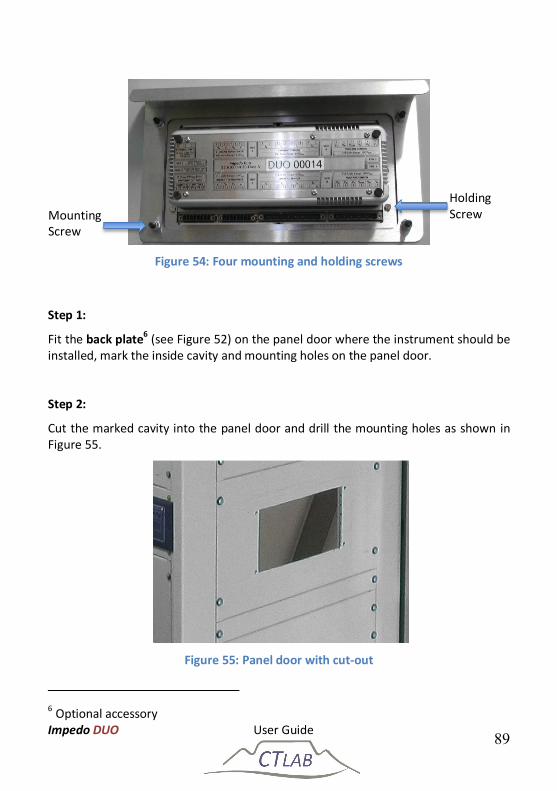
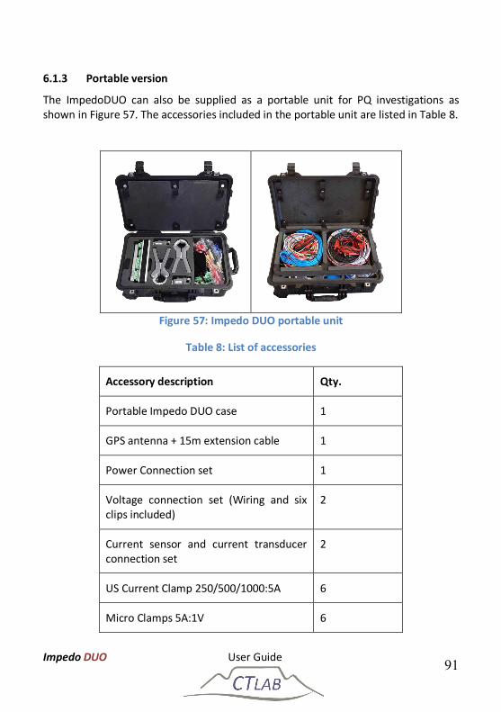
6 Impedo Duo Installation 88 6.1 Mounting the Impedo Duo .....................................................................88 6.1.1 Panel Mounting Installation ....................................................................... 88 6.1.2 19” Rack Mounting Installation ................................................................ 90 6.1.3 Portable version ............................................................................................. 91 6.2 Connections ...............................................................................................92 6.2.1 AC Power .......................................................................................................... 92
Impedo DUO User Guide 6
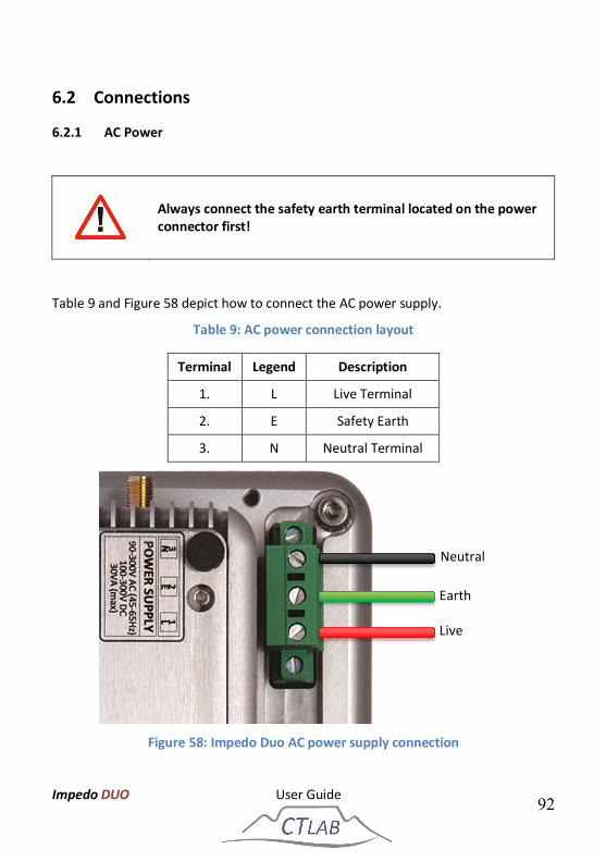
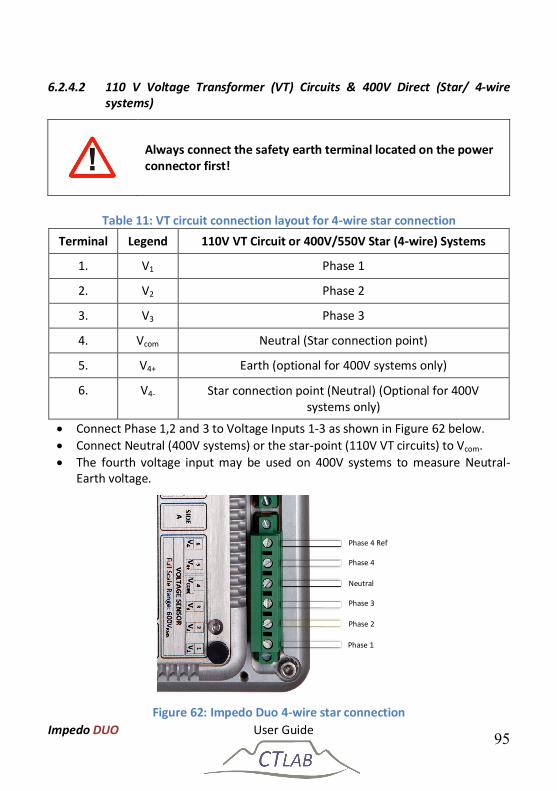
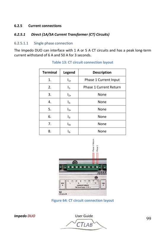
6.2.2 Power Over Ethernet (PoE) ....................................................................... 93 6.2.3 Instrument Activation .................................................................................. 93 6.2.4 Voltage connections ...................................................................................... 94 6.2.5 Current connections ..................................................................................... 99 6.2.6 Ethernet Based Communication ............................................................ 103 6.2.7 GPS ................................................................................................................... 103 6.2.8 3G / GPRS Modem ...................................................................................... 103
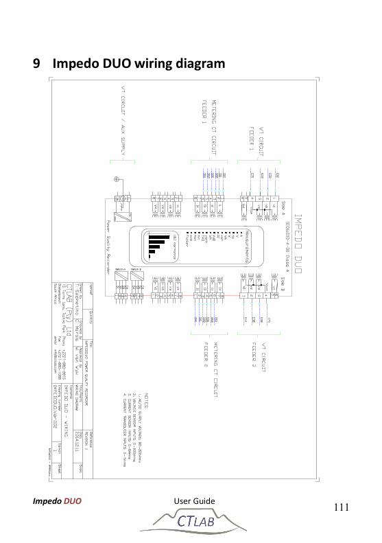
1 Safety Instructions This section provides information on safe handling, installation and commissioning of the Impedo DUO. Before carrying out any work on the equipment the user should be familiar with the contents of this document.
Reference should be made to the instrument’s wiring diagram and the ratings before any installation can commence.
1.1 Symbols
1. Notice Used to call attention to important information.
Caution
Used to indicate operating or maintenance procedures to be respected in order to prevent damage or destruction of equipment.
2. Warning
Used to call attention to potential dangerous situations or danger in general, that requires specific procedures to be respected in order to prevent personal injury.
1.2 Safety Standards Compliance The instrument complies with the IEC61010-1 safety standard:
Pollution: Degree 2
Over-voltage category: CAT III
Measurement category: CAT III
Impedo DUO User Guide 8
The instrument complies with the IEC60529 protection standard:
Penetration of dust & water: Class I
IP Rating: IP52
Inadvertent contact
1.3 General Safety Information Installation and maintenance of the instrument should only be performed by a qualified and certified electrician/technician with appropriate training and experience with high voltage and current devices.
The instrument must be installed in accordance with the approved national electrical codes.
If the instrument is used in a manner not specified by the manufacturer, protection from electric shock, fire, etc. provided by this equipment may be compromised.
When the instrument is in operation, dangerous voltages will be present in certain parts of the equipment. Failure to observe warning notices, incorrect use, or improper use may endanger personnel and the instrument and also cause personal injury or physical damage. The standard safety precautions must be followed while performing both the installation and service work.
The terminals exposed during installation, commissioning and maintenance may present a hazardous voltage unless the equipment is electrically isolated. Failure to properly isolate the instrument can create a risk of electric shock, injury or death.
Failure to earth the instrument will compromise the correct functioning of the internal protection circuitry of the instrument.
The user must inspect the instrument and all accessories before use; attention must be placed on inspecting:
Damage to instrument and accessories – do not use any damaged equipment.
The rating of the input terminals – Do not apply input voltages above the rating of the Instrument.
Do not expose the instrument to extreme moisture and or rain. Avoid use should the instrument be exposed to moisture/rain.
The digital output of the instrument must not be used for primary protection
Impedo DUO User Guide 9
functions. The digital outputs can however be used for secondary protection functions.
Impedo DUO is intended for indoor installation and use only. If it is required for use in an outdoor environment then it must be mounted in a specific cabinet or housing which will enable it to meet the requirements of IEC 60529 with the classification of degree of protection IP54 (dust and splashing water protected).
Do not use the instrument in situations where failure of the instrument can cause injury or death, or cause sufficient energy to be released that can start a fire.
1.4 Statements and Notices
1.4.1 Statement of reliability
The information in this manual has been reviewed and is believed to be entirely reliable, however, no responsibility is assumed for any inaccuracies. All material is for informational purposes only and is subject to change without prior notice. Please see www.ctlab.com for the latest copy of this document.
1.4.2 Proprietary rights
This publication contains information proprietary to CT Lab (Pty.) Ltd. By accepting and using this manual, you agree that the information contained herein will be used solely for the purpose of operating equipment of CT Lab (Pty.) Ltd.
1.4.3 Copyright
No part of this publication may be reproduced, transmitted, transcribed, stored in a retrieval system, or translated into any language or computer language, in any form, by any means, electronic, mechanical, magnetic, optical, chemical, manual, or otherwise, without the prior written consent of CT Lab (Pty.) Ltd., 15 Termo Lane, Techno Park, Stellenbosch
1.4.4 Trademarks
Impedo DUO, Vecto II, Osprey Lite, Osprey Pro, Xross-Trigger, Snapshot and 6th-sense are registered trademarks of CT Lab (Pty.) Ltd.
1.4.5 Validity and applicability of this document
This document is applicable to Impedo DUO V1.7.8. It will only be partially applicable to other firmware versions.
Impedo DUO User Guide 10
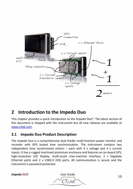
2 Introduction to the Impedo Duo This chapter provides a quick introduction to the Impedo Duo®. The latest version of this document is shipped with the instrument but all new releases are available at www.ctlab.com.
2.1 Impedo Duo Product Description The Impedo Duo is a comprehensive dual feeder multi-function power monitor and recorder with GPS locked time synchronisation. The instrument contains two independent time synchronised meters – each with 4 x voltage and 4 x current inputs. It has a rugged machined aluminium enclosure and features an on-board GPS, high-resolution LED Display, multi-touch man-machine interface, 2 x Gigabyte Ethernet ports and 2 x USB2.0 (HS) ports. All communication is secure and the instrument is password protected.
Impedo DUO User Guide 11
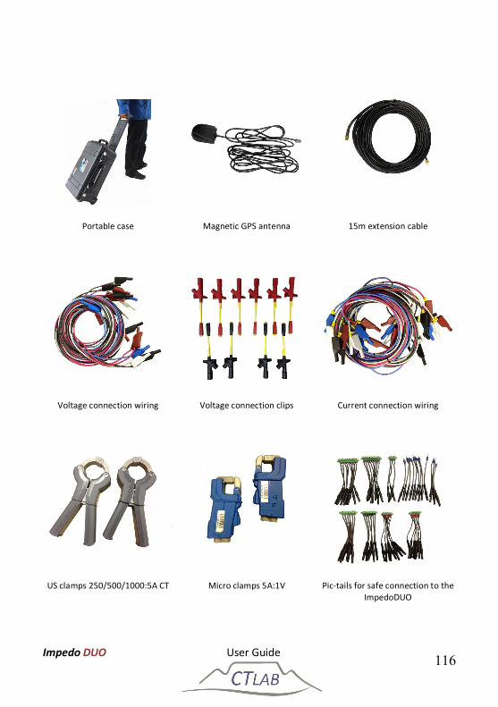
2.2 Receiving your Impedo Duo The Impedo DUO packaging is shown Figure 1 with the high-density foam cavity for the Impedo DUO and the accessories supplied with the instrument. Figure 2 shows the sealed ImpedoDUO box that is shipped.
Figure 1: Inside of the Impedo DUO box
Figure 2: Closed and strapped Impedo DUO box
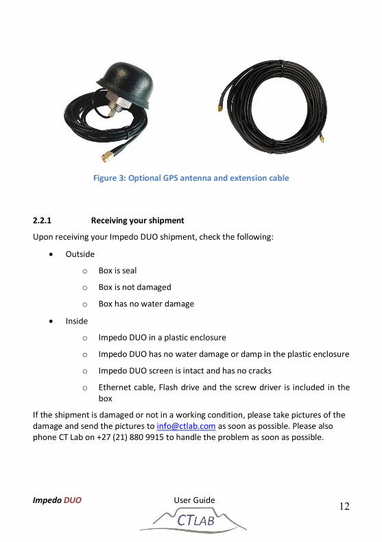
The Impedo DUO may be ordered with an optional GPS antenna with an extension cable as shown in Figure 3. Please contact CT Lab for more information regarding a GPS antenna-mounting bracket if required.
Impedo DUO User Guide 12
Figure 3: Optional GPS antenna and extension cable
2.2.1 Receiving your shipment
Upon receiving your Impedo DUO shipment, check the following:
Outside
o Box is seal
o Box is not damaged
o Box has no water damage
Inside
o Impedo DUO in a plastic enclosure
o Impedo DUO has no water damage or damp in the plastic enclosure
o Impedo DUO screen is intact and has no cracks
o Ethernet cable, Flash drive and the screw driver is included in the box
If the shipment is damaged or not in a working condition, please take pictures of the damage and send the pictures to [email protected] as soon as possible. Please also phone CT Lab on +27 (21) 880 9915 to handle the problem as soon as possible.
Impedo DUO User Guide 13
2.2.2 Unpacking the goods
Step Action
1 Remove all literature inside the box on top of the high-density foam
2 Remove the accessories in the accessories cavity on the right side of the box. Check that the standard accessories (see Section 2.2.1) are included.
3 Carefully remove the lid of the high-density foam enclosure
4 Remove the Impedo DUO from the cavity and inspect for damage
2.2.3 Return shipment
Should the instrument be returned to CT Lab due to damage during shipment or instrument failure, please follow these instructions:
1. Insert the instrument into a plastic bag to prevent water damage during shipment transit; and
2. Protect the instrument properly and also put it inside a padded box to prevent mechanical damage during transit.
3. Complete the fault report and sent it and the instrument to CT Lab.
o Notify [email protected], provide details on the instrument and how it was shipped and how it can be tracked and with a copy of the fault report.
If an instrument is returned to CT Lab due to damage during shipment please take picture of the box and the instrument before returning the instrument in the packaging supplied with the instrument.
The package and instrument remain the responsibility of the client until delivered to CT Lab.
Impedo DUO User Guide 14
2.3 Instrument Overview
2.3.1 Key Features
The Impedo DUO has two independent IEC 61000-4-30 Class A meters in one instrument with both voltages and currents for two 3-phase feeders.
1. Voltage inputs x 2:
Class A performance over all of the input range inclusive of 63.5 V (if L-N measurements are done in a 110 V line-line VT circuit)
6 terminals are used for 4 voltage input channels with maximum input ratings of 600 V.
o The first 4 terminals connect 3 different phase voltages such as in a 3-phase system.
o Input channel 1-3 is referenced to a neutral (4th terminal) connection. This 4th terminal acts as a reference channel and can be any phase voltage if a 3-phase line-line voltage circuit is measured.
o If it is a 3-phase line-neutral voltage circuit, then the 4th terminal will be connected to the neutral voltage.
o The 5th and 6th terminal is the 4th channel and a fully differential (2 terminal) input channel.
2. Current inputs x 2:
4 X 1/5 A CT inputs; and
4 X 1 Vrms differential current transducer inputs
3. Digital Outputs two sets:
3 X Switched outputs with 1 common
4. Digitisation of input signals
500 kHz sampling of primary input signals.
50 kHz is digitally retained and subjected to the IEC 61000-4-30 Class A signal processing requirements.
5. Power supply
PoE and/or a 90-300 V AC/DC power factor corrected power supply.
Impedo DUO User Guide 15
20 minutes power failure ride-through via an internal LiFePO4 battery.
6. Data storage
4 GB on-board storage providing data storage of all IEC 61000-4-30 voltage and current values of 10-minute and/or variable trended data up to the 64th harmonic component.
The ImpedoDUO utilise the first in first out principle on default but the instrument can also be configured to stop when the memory is full. The instrument can however record more than 6 years of 10 min trended parameters (including the harmonics and inter-harmonics) and more than 3 weeks of 3 sec data (harmonics and inter-harmonics).
The use of a SD card for data storage enhances the capability of
the instrument not to lose data, configuration or firmware if
without power for more than 1 year.
7. Time stamping
GPS time synchronization resulting in a time-stamping certainty better than 100 ns.
NTP time synchronization as an option.
8. Communication
Communication is via Ethernet.
Modbus over Ethernet.
DNP3 over Ethernet.
IEC 61850 – optional.
9. Advanced triggering
User-configurable triggering between different instruments: the patented Xross-Trigger feature (Described in the Osprey Lite user manual)
10. Configuration of instrument
Multi-touch user-interface provides configuration and real-time information display; or
Impedo DUO User Guide 16
By means of an Ethernet connection to a local laptop with Osprey Lite installed.
11. Data analysis and reporting
Osprey Lite is supplied free of charge and continuously updated.
Download from www.ctlab.com.
It generates both NRS 048 and EN 50160 PQ reports.
It allows basic and advanced analysis of PQ waveform events and trends.
Data can be exported to in .csv and PQDIF format for additional analysis in third party software packages.
Data downloading can be automated by configuration of the Impedo DUO with Osprey Lite.
All measurable PQ parameters can be recordable simultaneously.
2.3.2 Impedo DUO External Interfaces
2.3.2.1 Voltages
The two 3-phase voltage inputs to the Impedo DUO interfaces directly to 110 V VT circuits or directly to mains connections, which has to be less than 600 V line-to-neutral.
Voltage measurements are differential.
6 voltage input terminals are used for each meter.
Input channel 1-3 is referenced to a neutral (4th terminal) connection. This 4th terminal acts as a reference channel and can be connected to any phase voltage or neutral point if a 3-phase line-line voltage circuit is measured.
If it is a 3-phase line-neutral voltage circuit, then the 4th terminal will be connected to the neutral voltage.
The 5th and 6th terminal is the 4th differential channel.
Impedo DUO User Guide 17
o It can be used to for example, to measure the difference between neutral and earth.
2.3.2.2 Currents
Permanently installed 1 A or 5 A CT’s, or clamp-on CT’s interface directly to the galvanically isolated current inputs.
The instrument calculates the “missing current” by assuming the sum of all currents is zero. (Please refer to Section 2.4.4 for more info)
Alternatively, 1 VRMS voltage output current transducers can be used to measure current.
Current to voltage transducers can interface directly to 4 low voltage differential inputs. (Please refer to Section 2.4.5 for more info)
2.3.3 Power sources
The instrument is powered from a power factor corrected AC supply input (90–300 V AC/DC).
It can also be powered from an IEEE 802.3-2008 compliant PoE Plus (< 12 W) source.
The internal LiFePO4 battery powers the instrument in the absence of power. This battery guarantees 2,000 charge/discharge cycles. If cycled once per day, it translates to at least a 5-year useful life.
Please refer to Section 2.4.2 for more detail.
2.3.4 Communication
Two (2) Gigabyte Ethernet ports facilitate local and networked external communication. One port is used to interface with corporate networks (DHCP or fixed IP support). The second Ethernet port is used to create a local network by means of being a local DHCP server. Please refer to Section 0 for more detail.
The remote support software supports automatic service discovery protocols. Laptops, when connected to the Impedo DUO, will receive an IP from the instrument. The remote support software can automatically discover which instruments are connected to the local network.
Please refer to the Osprey LiteTM user manual for more information.
Impedo DUO User Guide 18
2.3.5 Osprey Pro (Enterprise Support)
When connected, each instrument automatically establishes a permanent secure communication link to a corporate server (local or internet based). An instrument management system (IMS) keeps track of each instrument’s location, configuration, health (telemetry) and PQ data recorded.
Downloading of data is automated and recorded data can be accessed via the Internet in graphical, tabled and report form as and when it becomes available. Raw data can be analysed in Osprey ProTM or exported for further analysis in for example Microsoft ExcelTM or MatlabTM.
Osprey ProTM simplify the analysis of waveform events such as dips and swells by the time-aggregation of multiple waveform events to single network incidents.
Osprey ProTM classify and report on recorded data according to industry standards such as NRS048, EN50160 and IEE1158. All communications are encrypted and each instrument is password protected. More information can please contact CT LAB.
2.3.6 Sampling Rate
The instrument samples all analog input signals at a rate of 500 kHz (10 000 samples per cycle) and then digitally down-sample the data to 50 kHz (1000 samples per cycle). All IEC 610000-4-30 parameters are calculated based on this 50 kHz resolution for both voltage and current.
Waveform and other events are triggered from the 500 kHz digitised waveforms. These waveforms are locked to the fundamental frequency to prevent multiple zero crosses.
Captured waveform data can be further subsampled to reduce stored data size. The user can configure the waveform-sampling rate from 1 kHz to 50 kHz.
Please refer to the Osprey LiteTM user manual for more information on selecting the down-sampling rate.
2.3.7 The 1/6th Sense
The Impedo DUO calculates a complete set of 1-cycle sliding RMS and fundamental phasor parameters on each of the 3 voltage phases resulting in a resolution of 6 values per cycle per phase. The IEC 61000-4-30 Class A requirements are based on a ½ cycle sliding approach. This higher resolution data improves the detail of the event profile and enable more accurate depth/duration calculations.
Impedo DUO User Guide 19
Please refer to the Osprey LiteTM user manual for more information on 1/6th cycle data.
2.3.8 Event Recording
Users can customise the recording of an event. The IEC 610000-4-30 definition of for example a dip event, can be changed to improve the understanding of phenomena of concern.
Upper and/or lower thresholds to define an event can be set by the user based on waveform, 1/6th sense, 10/12-cycle block and aggregated parameters.
Single-phase and multiple-phase triggers can be defined.
When a threshold is exceeded, the Impedo DUO will retain pre- and post-diagnostic information of the event.
Please refer to the Osprey LiteTM user manual for more information on event recordings.
2.3.9 10/12-Cycle Block Recording
The Impedo DUO records all RMS and harmonic data from each 10/12-cycle block (≈200ms block) for both voltage and current as prescribed by the Class A performance requirements of the IEC 61000-4-30, edition 3.
These block values contain both amplitude and angle information of all voltage and current harmonic components up to the 64th harmonic order.
Each block is time-stamped with a 1 s time resolution and within a 100 ns time uncertainty1.
The user can average N x blocks to reduce the sampling rate for the number of blocks up to 299 blocks2.
Please refer to the Osprey LiteTM user manual for more information on 10/12 cycle block intervals and down sampling.
1 When GPS synchronized 2 Averaged block harmonic and unbalance phasors do not contain angle information.
Impedo DUO User Guide 20
2.3.10 Variable time interval trends
10/12-Cycle block RMS and harmonic parameters are aggregated according to IEC 61000-4-30 requirements over a user-defined time interval (1 to 30 minutes).
Clock synchronised parameters are time-stamped with a 1 second time resolution.
2.3.11 Synchrophasors
The Impedo DUO is also a Phasor Measurement Recorder (PMU). Recording of 50 Hz (or 60 Hz) synchrophasors can be activated in the configuration setup. Please refer to the Osprey LiteTM user manual for more information.
Note that this can generate large amounts of data. Contact CT LAB for support if interested in a PMU application.
Impedo DUO User Guide 21
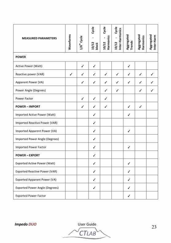
2.3.12 Measured parameters
MEASURED PARAMETERS
Wav
efor
ms
1/6th
Cyc
le
10/1
2 -
Cycl
e bl
ock
10/1
2 -
Cycl
e H
arm
onic
s
10/1
2 -
Cycl
e In
ter-
Har
mon
ics
Aggr
egat
ed
Tren
ds
Aggr
egat
ed
Har
mon
ics
Aggr
egat
ed
Inte
r-H
arm
VOLTAGE
Frequency (Hz) ✓ ✓ ✓
Voltage (Volt) ✓ ✓ ✓ ✓ ✓ ✓ ✓ ✓
Voltage (% of Nominal) ✓ ✓ ✓ ✓ ✓ ✓ ✓
Voltage (% of Fundamental) ✓ ✓ ✓ ✓
Voltage Phase Angle (Degrees) ✓ ✓ ✓
Voltage Unbalance (%) ✓ ✓ ✓ ✓ ✓
V-Positive Amplitude (Volt) ✓ ✓
V-Positive Angle (Degrees) ✓
V-Negative Amplitude (Volt) ✓ ✓
V-Negative Angle (Degrees) ✓
V-Zero Amplitude (Volt) ✓ ✓
V-Zero Angle (Degrees) ✓
Voltage Under-Deviation (%) ✓ ✓
Voltage Over-Deviation (%) ✓ ✓
Voltage THD (%) ✓ ✓
Flicker (Pst) ✓ ✓
Flicker (Plt) ✓
Impedo DUO User Guide 22
MEASURED PARAMETERS
Wav
efor
ms
1/6th
Cyc
le
10/1
2 -
Cycl
e bl
ock
10/1
2 -
Cycl
e H
arm
onic
s
10/1
2 -
Cycl
e In
ter-
Har
mon
ics
Aggr
egat
ed
Tren
ds
Aggr
egat
ed
Har
mon
ics
Aggr
egat
ed
Inte
r-H
arm
CURRENT
Current (Ampere) ✓ ✓ ✓ ✓ ✓ ✓ ✓ ✓
Current (% of Fundamental) ✓ ✓ ✓ ✓ ✓
Current Phase Angle (Degrees) ✓ ✓ ✓
Current Unbalance (%) ✓ ✓ ✓ ✓ ✓
I-Positive Amplitude (Ampere) ✓ ✓
I-Positive Angle (Degrees) ✓
I-Negative Amplitude (Ampere) ✓ ✓
I-Negative Angle (Degrees) ✓
I-Zero Amplitude (Ampere) ✓ ✓
I-Zero Angle (Degrees) ✓
Current THD (%) ✓ ✓
Crest Factor ✓ ✓ ✓
K-Factor ✓ ✓
Impedo DUO User Guide 23
MEASURED PARAMETERS
Wav
efor
ms
1/6th
Cyc
le
10/1
2 -
Cycl
e bl
ock
10/1
2 -
Cycl
e H
arm
onic
s
10/1
2 -
Cycl
e In
ter-
Har
mon
ics
Aggr
egat
ed
Tren
ds
Aggr
egat
ed
Har
mon
ics
Aggr
egat
ed
Inte
r-H
arm
POWER
Active Power (Watt) ✓ ✓ ✓
Reactive power (VAR) ✓ ✓ ✓ ✓ ✓ ✓ ✓ ✓
Apparent Power (VA) ✓ ✓ ✓ ✓ ✓ ✓ ✓
Power Angle (Degrees) ✓ ✓ ✓ ✓
Power Factor ✓ ✓ ✓
POWER – IMPORT ✓ ✓ ✓ ✓ ✓
Imported Active Power (Watt) ✓ ✓
Imported Reactive Power (VAR) ✓
Imported Apparent Power (VA) ✓ ✓
Imported Power Angle (Degrees) ✓
Imported Power Factor ✓ ✓
POWER – EXPORT ✓
Exported Active Power (Watt) ✓ ✓
Exported Reactive Power (VAR) ✓ ✓
Exported Apparent Power (VA) ✓ ✓
Exported Power Angle (Degrees) ✓ ✓
Exported Power Factor ✓
Impedo DUO User Guide 24
2.3.13 Technical Specification
VOLTAGE INPUTS
Number of channels 2 sets of 4 x differential inputs (3/4 Wire + 4th Diff)
Measurement input range 0 – 600 VRMS
Voltage measurement Single Phase, 3-Phase (Star, Delta), DC
Input impedance/channel > 1 MΩ
CURRENT SENSOR INPUTS
Number of channels 2 sets of 4 x galvanically isolated inputs
Measurement input range 0 - 5.0 ARMS
Maximum continuous current 6.0 ARMS
3 sec over-current withstand 50 A
VA Burden @ 5A < 1 VA
Galvanic isolation 1,000 V
CURRENT TRANSDUCER INPUTS
Number of channels 2 sets of 4 differential inputs
Measurement input range 0 – 1.0 VRMS (±1.414V Peak)
Input impedance/channel > 1 MΩ
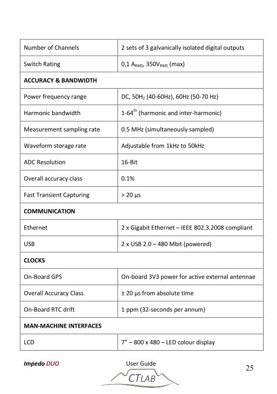
DIGITAL OUTPUTS
Impedo DUO User Guide 25
Number of Channels 2 sets of 3 galvanically isolated digital outputs
Switch Rating 0,1 ARMS, 350VRMS (max)
ACCURACY & BANDWIDTH
Power frequency range DC, 50HZ (40-60Hz), 60Hz (50-70 Hz)
Harmonic bandwidth 1-64th (harmonic and inter-harmonic)
Construction Aluminium, 220mm x 131mm x 85mm (L x W x H)
Mounting options 3U-19” Rack, Panel Mount, Portable Case
Electrical connections Pluggable screw type (screw lock-down)
Electrical isolation class 600V Class II
Operating temperature 0 ⁰C to 75 ⁰C
COMPLIANCE
PQ Measurement IEC 61000-4-30, Class A
Harmonics IEC 61000-4-7
Flicker IEC 61000-4-15
SCADA IEC 61850
Impedo DUO User Guide 27
2.4 Impedo Duo External Interfaces
2.4.1 Physical Appearance
Figure 4 shows the front of the Impedo Duo. A multi-touch user interface; high resolution LCD and OLED display icons are shown.
To access a function on the LCD display, simply tap the respective icon once. Android is used for the on board user interface and the typical android conventions apply. The embedded software functionality is described in Section 5.
The OLED display on the right side of the front panel provides the user with operational and health information of the instrument. Detail on interpreting the status icons is provided in Section 4.
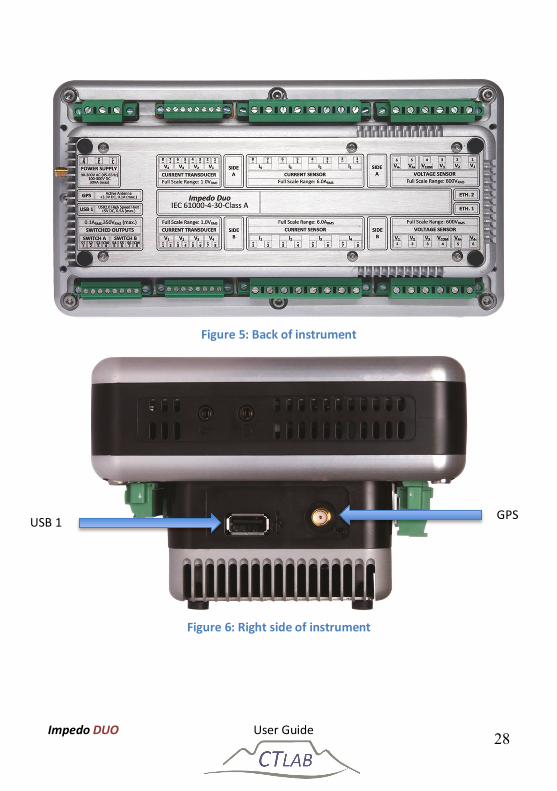
Figure 5 shows the back of the instrument. A name plate provides the name and serial number of the instrument, as well as a detail layout of the external interfaces of the instrument including the inputs ratings. A detail description of the external intrafaces of the instrument is provided in Sections 2.4.2 to 2.4.11.
Figure 4: Front of instrument
OLED
LCD Display
Impedo DUO User Guide 28
Figure 5: Back of instrument
Figure 6: Right side of instrument
GPS USB 1
Impedo DUO User Guide 29
Figure 7: Left side of instrument
Figure 6 show the right side of the instrument with USB port 1 and the GPS antenna connector. Figure 7 shows the left side of the instrument with USB port 2 and the two Ethernet communication ports.
2.4.2 Power Supply
The Impedo Duo can be powered and charged via a power factor corrected universal input mains supply or via IEEE 802.3-2008 compliant Power over Ethernet (PoE). A built in LiFePO4
battery will power the instrument for up to ±20min in the absence of power. This battery has a design life expectancy of more than 2,000 charge/discharge cycles.
The Power Supply port contains 3 terminals on a removable lockable plug. Each terminal can accommodate conductors with size up to 2.5mm2.
The supply voltage input range is from 90 VRMS to 300 VRMS AC or DC (42-69Hz for AC sources). This enables the instrument to be powered from the 110 V VT terminals, 230 V auxiliary supply or the DC bus.
ETH 1
USB 2
ETH 2
Impedo DUO User Guide 30
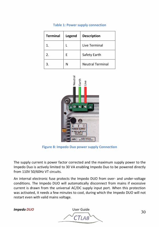
Table 1: Power supply connection
Terminal Legend Description
1. L Live Terminal
2. E Safety Earth
3. N Neutral Terminal
Figure 8: Impedo Duo power supply Connection
The supply current is power factor corrected and the maximum supply power to the Impedo Duo is actively limited to 30 VA enabling Impedo Duo to be powered directly from 110V 50/60Hz VT circuits.
An internal electronic fuse protects the Impedo DUO from over- and under-voltage conditions. The Impedo DUO will automatically disconnect from mains if excessive current is drawn from the universal AC/DC supply input port. When this protection was activated, it needs a few minutes to cool, during which the Impedo DUO will not restart even with valid mains voltage.
Neu
tral
Eart
h
Live
Impedo DUO User Guide 31
During a power interruption/failure, the internal battery will power the instrument for ± 20 minutes. When the battery charge drop below 50% of full capacity (0% on the OLED display), the instrument will gracefully shut down to protect the battery.
When power is restored, the instrument will automatically restart within 60 seconds if the battery status is above 30% (of full capacity) or first recharge until the battery reach 30% and only then restart. During this period an icon on the OLED-display will indicate a battery-warning symbol.
Figure 9: Ethernet ports
The Safety Earth terminal connects all exposed metal parts to external earth.
Port 2
Port 1
Impedo DUO User Guide 32
IEEE 802.3-2008 compliant Power over Ethernet (PoE) Plus is available on both Ethernet ports at 30 to 60 V. The PoE capability enables the Impedo Duo to be powered through the communication infrastructure. The Impedo Duo will therefore be available at all times if the communication infrastructure stays active.
2.4.3 Voltage Inputs
Each individual meter contains 4 resistive differential voltage inputs made up of 6 terminals as shown in Figure 10 and Figure 11.
The first 4 terminals are used for 3 voltage inputs. V1, V2 and V3 are Neutral (Vcom) referenced (V1-N, V2-N, V3-N) in a four wire Star connection (Figure 10) and referenced to any one of the three phases in a 3 wire Delta connection (Figure 11).
Terminal 5 and 6 are used for the 4th (V4+, V4-) voltage input. It is a full differential measurement normally used for Neutral to Earth measurement.
The voltage inputs terminals can accommodate conductors with sizes up to 2.5 mm2.
Figure 10 shows the voltage connections for a 3-phase 4-wire star system. Power is calculated per phase and arithmetically added to obtain the 3-phase powers.
Figure 11 shows the voltage connections for a 3-phase 3-wire delta connection. Three-phase power is calculated by the 2-watt meter method.
If voltages are connected in star (4-wire) on the terminals the user can select star (4-wire) or delta (3-wire) topology in the software.
Impedo DUO User Guide 33
Figure 10: Impedo Duo 4-wire star connection on meter A
Figure 11: Impedo Duo 3-wire delta connection on meter B
Phas
e 3
Phas
e 2
Phas
e 1
Phas
e 4
Ref
Phas
e 4
Neu
tral
Phase 3
Phase 2
Phase 1
Impedo DUO User Guide 34
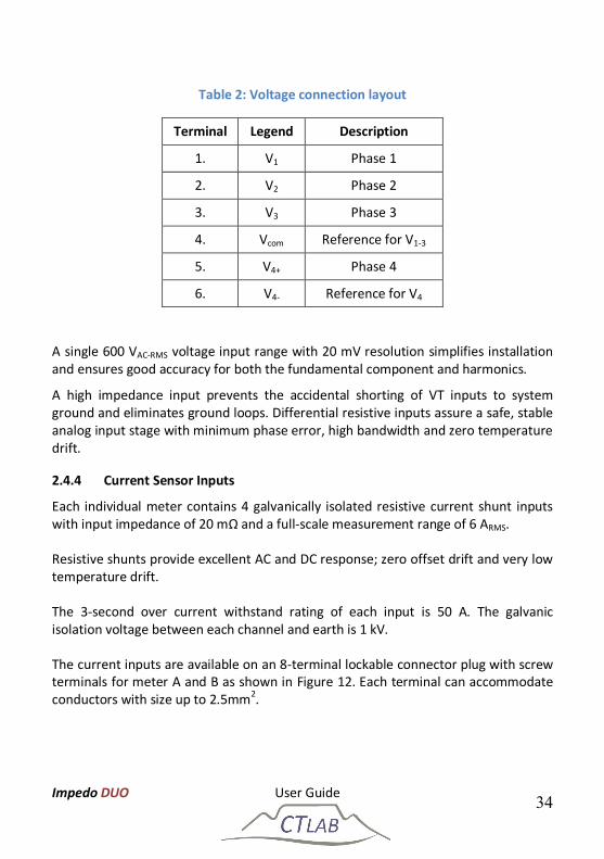
Table 2: Voltage connection layout
Terminal Legend Description
1. V1 Phase 1
2. V2 Phase 2
3. V3 Phase 3
4. Vcom Reference for V1-3
5. V4+ Phase 4
6. V4- Reference for V4
A single 600 VAC-RMS voltage input range with 20 mV resolution simplifies installation and ensures good accuracy for both the fundamental component and harmonics.
A high impedance input prevents the accidental shorting of VT inputs to system ground and eliminates ground loops. Differential resistive inputs assure a safe, stable analog input stage with minimum phase error, high bandwidth and zero temperature drift.
2.4.4 Current Sensor Inputs
Each individual meter contains 4 galvanically isolated resistive current shunt inputs with input impedance of 20 mΩ and a full-scale measurement range of 6 ARMS.
Resistive shunts provide excellent AC and DC response; zero offset drift and very low temperature drift.
The 3-second over current withstand rating of each input is 50 A. The galvanic isolation voltage between each channel and earth is 1 kV.
The current inputs are available on an 8-terminal lockable connector plug with screw terminals for meter A and B as shown in Figure 12. Each terminal can accommodate conductors with size up to 2.5mm2.
Impedo DUO User Guide 35
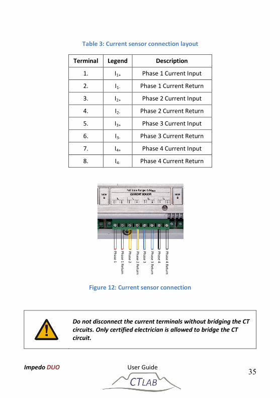
Table 3: Current sensor connection layout
Terminal Legend Description
1. I1+ Phase 1 Current Input
2. I1- Phase 1 Current Return
3. I2+ Phase 2 Current Input
4. I2- Phase 2 Current Return
5. I3+ Phase 3 Current Input
6. I3- Phase 3 Current Return
7. I4+ Phase 4 Current Input
8. I4- Phase 4 Current Return
Figure 12: Current sensor connection
Do not disconnect the current terminals without bridging the CT circuits. Only certified electrician is allowed to bridge the CT circuit.
Phase 3
Phase 2
Phase 1
Phase 4 Return
Phase 4
Phase 1 Return
Phase 2 Return
Phase 3 Return
Impedo DUO User Guide 36
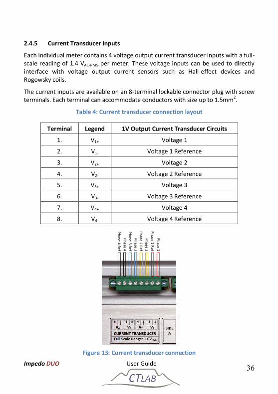
2.4.5 Current Transducer Inputs
Each individual meter contains 4 voltage output current transducer inputs with a full-scale reading of 1.4 VAC-RMS per meter. These voltage inputs can be used to directly interface with voltage output current sensors such as Hall-effect devices and Rogowsky coils.
The current inputs are available on an 8-terminal lockable connector plug with screw terminals. Each terminal can accommodate conductors with size up to 1.5mm2.
Table 4: Current transducer connection layout
Terminal Legend 1V Output Current Transducer Circuits
1. V1+ Voltage 1
2. V1- Voltage 1 Reference
3. V2+ Voltage 2
4. V2- Voltage 2 Reference
5. V3+ Voltage 3
6. V3- Voltage 3 Reference
7. V4+ Voltage 4
8. V4- Voltage 4 Reference
Figure 13: Current transducer connection
Phase 2 Ref Phase 3 Ref Phase 4 Ref
Phase 1 Phase 1 Ref
Phase 4
Phase 3
Phase 2
Impedo DUO User Guide 37
2.4.6 Relay Outputs
Six relay outputs (100 mARMS, 350 VRMS) are used to provide pulsed outputs or to control external processes. The outputs are arranged into 2 galvanically isolated clusters (1 kV isolation); each containing 3 switched contacts with a common return path.
The relay outputs are available on an 8-terminal lockable connector plug with screw terminals. Each terminal can accommodate conductors with size up to 1.5mm2.
Table 5: Relay switch connection layout
Terminal Legend Description
1. S1 Switch A1
2. S2 Switch A2
3. S3 Switch A3
4. Cm Switch A Common
5. S4 Switch B1
6. S5 Switch B2
7. S6 Switch B3
8. Cm Switch B Common
Figure 14: Relay switch connection layout
Switc
h B
Com
mon
Switc
h B3
Sw
itch
B2
Switc
h B1
Sw
itch
A Co
mm
on
Switc
h A3
Switc
h A2
Switc
h A1
Impedo DUO User Guide 38
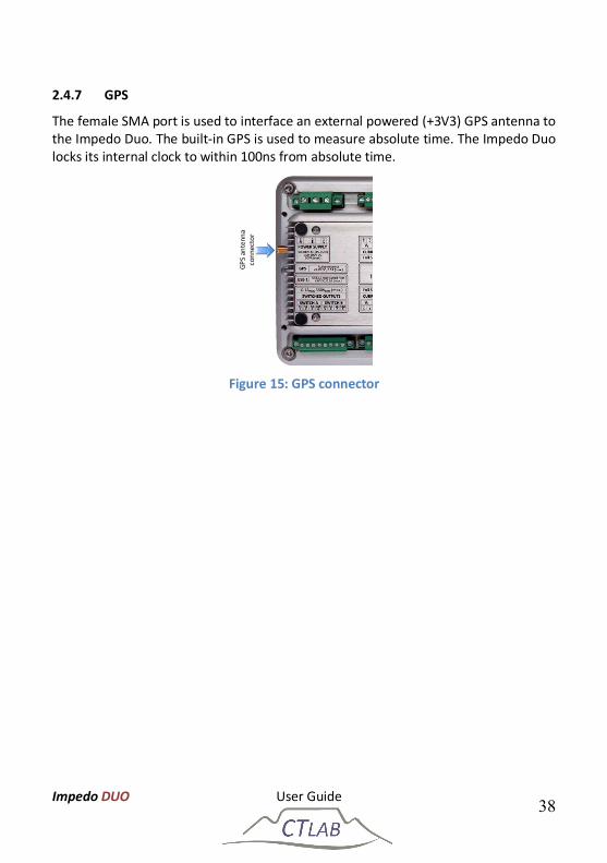
2.4.7 GPS
The female SMA port is used to interface an external powered (+3V3) GPS antenna to the Impedo Duo. The built-in GPS is used to measure absolute time. The Impedo Duo locks its internal clock to within 100ns from absolute time.
Figure 15: GPS connector
GPS
ante
nna
conn
ecto
r
Impedo DUO User Guide 39
2.4.8 Ethernet Ports
The instrument has two Gigabit Ethernet ports as shown in Figure 16. The IP address of port 1 is fixed at 192.168.7.1. The instrument serves as a DHCP server for the network connected to this port. The IP address of port 2 can be set using the GUI (see Section 0) and is also used to interface to GPRS/3G routers for remote communication.
Do not connect Ethernet port 1 to a network with an active DHCP server, as this may cause the network to stop functioning properly
The IP address of Ethernet port 1 is fixed at 192.168.7.1
The instrument serves as a DHCP server for equipment
connected to port 1
IEEE 802.3-2008 compliant Power over Ethernet (PoE) is available on both Ethernet ports. The PoE capability enables the Impedo Duo to be powered through the communication infrastructure. The Impedo Duo will therefore be available at all times while the communication infrastructure stays on-line.
Figure 16: Ethernet ports
ETH 1 ETH 2
Impedo DUO User Guide 40
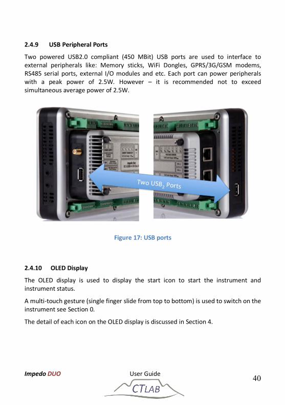
2.4.9 USB Peripheral Ports
Two powered USB2.0 compliant (450 MBit) USB ports are used to interface to external peripherals like: Memory sticks, WiFi Dongles, GPRS/3G/GSM modems, RS485 serial ports, external I/O modules and etc. Each port can power peripherals with a peak power of 2.5W. However – it is recommended not to exceed simultaneous average power of 2.5W.
Figure 17: USB ports
2.4.10 OLED Display
The OLED display is used to display the start icon to start the instrument and instrument status.
A multi-touch gesture (single finger slide from top to bottom) is used to switch on the instrument see Section 0.
The detail of each icon on the OLED display is discussed in Section 4.
Impedo DUO User Guide 41
2.4.11 Multi-Touch Display
A high-resolution full colour multi-touch enabled display is used to
Configure the instrument – preferences and PQ monitors
Provide an installation wizard with real-time voltage and current information during installation
Provide real-time waveform, RMS phasor and harmonic feedback
The detail of each icon on the Multi-Touch display is discussed in Section 5.
2.5 Firmware The Impedo DUO firmware revision is shown on the OLED and also in Osprey LiteTM when connected to the instrument, please see Osprey LiteTM user manual for more information.
2.5.1 Upgrading
The Impedo DUO support firmware upgrade via Osprey LiteTM, please see Osprey LiteTM user manual for more information.
Impedo DUO User Guide 42
3 Operating Instructions
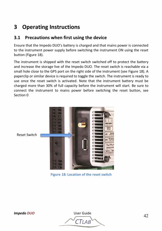
3.1 Precautions when first using the device Ensure that the Impedo DUO’s battery is charged and that mains power is connected to the instrument power supply before switching the instrument ON using the reset button (Figure 18).
The instrument is shipped with the reset switch switched off to protect the battery and increase the storage live of the Impedo DUO. The reset switch is reachable via a small hole close to the GPS port on the right side of the instrument (see Figure 18). A paperclip or similar device is required to toggle the switch. The instrument is ready to use once the reset switch is activated. Note that the instrument battery must be charged more than 30% of full capacity before the instrument will start. Be sure to connect the instrument to mains power before switching the reset button, see Section 0
Figure 18: Location of the reset switch
Reset Switch
Impedo DUO User Guide 43
3.2 Checking the Battery Level After switching the instrument ON with the reset button (Section 3.1), touch the LCD screen to activate the multi-touch screen and OLED. If the OLED display does not show a flashing power icon as shown in Section 0, the battery is discharged too far and the instrument will not power up before sufficient battery charge level has been obtained. When the instrument is connected to mains (see Section 6.2.1) and the battery icon flash on the OLED the instrument battery level is below the operational level. Wait until the battery disappears and the flashing power icon is visible on touching the LCD screen.
The fast charge mode will require 2 hours to restore the battery to 100% state of charge (instrument must be powered down). A maximum of 40 minutes charge time is required to restore to the point where the instrument can be started. See Section 4.6 for a description of the battery status indicator that is visible once the instrument is switched on.
The instrument will not power up until sufficiently charged (see Section 4.6)
Impedo DUO User Guide 44
3.3 Powering up the Impedo Duo The Impedo Duo does not contain a physical power switch. A start gesture on the OLED display is required to switch the instrument ON (single finger slide from top to bottom).
On the first touch (anywhere on the glass panel), the Impedo Duo Power Distribution Unit (PDU) will scan the battery status. If sufficient power is available, the PDU will switch on the OLED to display a power switch icon. When touching the power switch icon, the PDU will animate the gesture required to switch on the instrument.
A small processor icon followed by a check mark icon will display on the OLED after recognition of a valid start gesture. The check mark symbol indicates successful booting of the embedded operating system. Next, the main display will show a start-up animation, which is then replaced by the final user interface once booting completed. The OLED will show the running information status.
Power-switch icon
Booting operating system
Operating system booted
The instrument will not power up until sufficiently charged (see Section 4.6)
External power is required if no response was received on the OLED display
Impedo DUO User Guide 45
3.4 Impedo Duo Unlock Screen The Impedo Duo will switch the main display off, after ±20 seconds without input from the user, to save power and to protect the instrument from unauthorised access. Touching the glass panel will switch on main display with the unlock-screen with an unlock button on the upper right corner of the screen as shown in Figure 19. The unlock-screen is password protected, the user may choose to enable or disable password protection. Touching the power off button (Section 3.5) will immediately return the device to the unlock screen. Refer to Section 5.7.3.4 for detail on setting passwords for the Impedo Duo.
Password protection is disabled by default
Figure 19: Impedo Duo unlock screen
Impedo DUO User Guide 46
3.5 Shutting down There is no physical power OFF button on the Impedo Duo. To power off the instrument, first unlock the user interface (UI). If necessary, terminate the current running application. Press and hold the power off button (see below) located on the bottom of the display. A dialog will pop up to confirm the action. Select OK to power off the device. The shutdown sequence may take up to 60 seconds.
Power off button
The shutdown sequence may take up to 60 seconds
If the power off button is released before the power off confirmation dialog is displayed, the device will go to the unlock screen
Impedo DUO User Guide 47
3.6 Power Cycling with the Reset Switch The Impedo Duo PDU stays powered even if the main processor is powered off. In this mode the built-in RTC the PDU and the health sensors receive power. After being fully charged, the Impedo Duo can be safely stored in this state for up to 3 months. Power can be removed from the entire instrument by the reset switch. The reset switch is reachable via a small hole close to the GPS port on the right side of the instrument (see Section 3.1, Figure 19). A paperclip or similar device is required to toggle the switch. The instrument is powered when the switch is in the depressed state. Note that removing power from the instrument also removes power from the RTC.
Upon start-up after a power cycle the RTC is in an unknown state and the instrument must first be connected to a valid time source (GPS or NTP) to ensure it measures correctly.
After power cycling the instrument with the reset switch, the RTC is in an undefined state – the PQ recording system will require a valid time source after power up before it can function correctly
Impedo DUO User Guide 48
4 OLED Information Display The OLED information display is located on the right side of the front panel, as depicted in Figure 4. It is used to provide permanent visual feedback of the instrument status as shown in Figure 20.
Figure 20: ImpedoDUO OLED display
4.1 Meter points If no meter icon is displayed or is crossed out, the instrument is not recording. The reason may be that the instrument does not have valid time, or that the recording subsystem was disabled (see Section 5.1.2).
Meter side A is configured and recording
Meter side A is configured and recording
Meter side A is not configured and not recording
Meter side A is not configured and not recording
Time and Date
Ethernet connec vity
Time source
Ba ery Status
Firmware version
Serial Number
Meter points
IP address
Temperature
On-Board Storage Usage
Connec on to server
Impedo DUO User Guide 49
4.2 Serial Number The instrument serial number is displayed below the meter point icons as shown in Figure 20. This number must match the serial number on the nameplate plate of the instrument.
4.3 IP Address If a live Ethernet cable is plugged into ETH 2, the IP address displayed on the OLED is either the assigned static IP address or the IP address received via a DCHP server on the network when configured to receive a DHCP IP address. If no cable is plugged into ETH 2, the IP address is the fixed IP addressed as for ETH 1. Refer to Section 0 for instructions on configuring ETH 2.
4.4 Firmware Version The current firmware version is displayed below the IP address as shown in Figure 20.
4.5 Temperature
The temperature icon shows the internal temperature at which the device is currently operating.
4.6 Battery Status The Impedo Duo will automatically power-off when the battery is depleted with absence of the primary power source. The battery status icon indicates the current charge level as shown in Figure 20. The instrument will power-up automatically when external power is applied. If the battery was depleted below a safe operating point, but external power is available, the instrument will still power up, but indicate that no surplice charge is available. Should external power fall away during this period, the instrument will immediately power down.
If the battery was depleted below the point where the instrument can be powered up, a battery icon will display when power is applied to the instrument and the OLED is touched. If no external power is available, the battery icon will not be displayed.
The surplice battery charge available, and battery currently not charging
Impedo DUO User Guide 50
The surplice battery charge available, and battery currently charging
The charge time remaining until the system will have surplice charge available and have ride through
The battery is too low to safely power-up the instrument
4.7 On-Board Storage Usage
The percentage of disc space used is displayed on the OLED as shown in Figure 20.
If the instrument is currently deleting data, the disk usage will be replaced by a trashcan. Once completed the disk usage icon will replace the trashcan again.
4.8 Time source The Impedo Duo has three sources of time. It can automatically determine which source to use. The user can override the automatic selection and specify which time source to use, see Section 5.7.3.3. The current selected time source is shown on the OLED display (Figure 20) with one of three icons.
No synchronisation with a time source for example, GPS or NTP (the internal RTC, with an accuracy of 10 ppm, can drift up to 0.86s per day)
NTP time synchronisation is available with a permanent internet connection, enabling time accuracy of typically 20ms to the NTP time source.
GPS time synchronisation is available with an active external GPS antenna and enables time to be managed to within 100 ns accuracy.
Impedo DUO User Guide 51
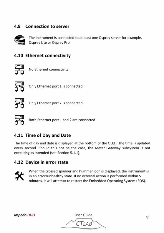
4.9 Connection to server
The instrument is connected to at least one Osprey server for example, Osprey Lite or Osprey Pro.
4.10 Ethernet connectivity
No Ethernet connectivity
Only Ethernet port 1 is connected
Only Ethernet port 2 is connected
Both Ethernet port 1 and 2 are connected
4.11 Time of Day and Date The time of day and date is displayed at the bottom of the OLED. The time is updated every second. Should this not be the case, the Meter Gateway subsystem is not executing as intended (see Section 5.1.1).
4.12 Device in error state
When the crossed spanner and hummer icon is displayed, the instrument is in an error/unhealthy state. If no external action is performed within 5 minutes, it will attempt to restart the Embedded Operating System (EOS).
Impedo DUO User Guide 52
5 Embedded Operating Software (EOS) The Embedded Operating System (EOS) is based on a dual Linux/Android configuration. Linux provides infrastructure for low-level functions, and Android provides the Graphical User Interface (GUI). The Impedo Duo is supported by the Osprey Lite and Osprey Pro software suites.
The latest version of Osprey Lite is available for download at www.ctlab.com. Please refer to the document Osprey Lite User Guide for information on using Osprey Lite to interact with the Impedo Duo.
For information about Osprey Pro, please contact CT LAB.
5.1 EOS Subsystems
5.1.1 Meter Gateway
All external communication is handled by Meter Gateway. It serves as the main control subsystem of the Impedo Duo. As such, when Meter Gateway is not running remote communication is not possible. The built-in watchdog will restart Meter Gateway if it should become non-responsive. Restarting Meter Gateway has no impact on PQ data capturing and recording.
Meter Gateway is responsible for updating the OLED display. If the time is updated every second, Meter Gateway is running. It houses (amongst others) the following components:
Space Reclaimer This component is part of Meter Gateway, and is responsible for deleting data as the internal storage becomes full. See Section 5.7.3.1 for details on configuring Space Reclaimer.
Health-Manager This component is part of Meter Gateway, and is responsible for powering off the instrument when health parameters exceed their limits (see Section 5.7.3.2 for details).
Time-Master This component is part of Meter Gateway, and is responsible for managing time on the instrument. It determines when time is valid, and selects the best source of time. Section 0 describes its configuration.
Modbus This component is part of Meter Gateway, and is responsible for serving Modbus data.
Impedo DUO User Guide 53
5.1.2 Storer
Storer is the PQ recording subsystem. If it is running the two meter point status icons are shown at the top of the OLED status display (see Section 4.1). See the Osprey Lite user manual for more information on the restart procedure of the Storer.
5.2 Communicating with the Impedo Duo All communication with the Impedo Duo is IP based. To secure communication over open networks, all traffic is encrypted. The encryption requires two passwords – the fleet password and the instrument key.
The fleet password is a shared secret across all servers and instruments belonging to the fleet. The fleet password must be entered on the Impedo Duo using Registration (see Section 5.6).
The instrument key is unique to each instrument and comes preloaded on the instrument. The key is also provided on the USB storage device shipped with the instrument. In order to communicate with the instrument the instrument key must be loaded into the server (see Osprey Lite User Guide for instructions on registering an instrument with Osprey Lite).
The Impedo Duo communicates using several well-known ports. Ensure that ports 27030 – 27045 are not blocked by any firewall between the instrument and the Osprey server. These ports must also be forwarded should any network address translation occur between the instrument and the Osprey server.
Both the fleet password and the instrument key are required before communication with the Impedo Duo is possible
The Impedo Duo communicate on ports 27030 – 27045
Impedo DUO User Guide 54
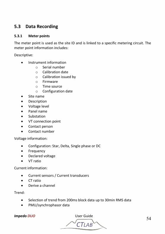
5.3 Data Recording
5.3.1 Meter points
The meter point is used as the site ID and is linked to a specific metering circuit. The meter point information includes:
Descriptive:
Instrument information o Serial number o Calibration date o Calibration issued by o Firmware o Time source o Configuration date
Site name Description Voltage level Panel name Substation VT connection point Contact person Contact number
Voltage information:
Configuration: Star, Delta, Single phase or DC Frequency Declared voltage VT ratio
Current information:
Current sensors / Current transducers CT ratio Derive a channel
Trend:
Selection of trend from 200ms block data up to 30min RMS data PMU/synchrophasor data
Impedo DUO User Guide 55
Monitors:
Selection of IEC61000-4-30 event monitors
Should the user require the full list of descriptive information as provided above, please contact CT Lab to unlock the full list, as the instrument only present some of the above information.
A meter point can be re-used when an instrument is re-installed for instance during an investigation or if the instrument was moved for a period of time by attaching the meter point during installation. A meter point is detached in Osprey Lite or on the Impedo DUO in the configuration app to stop recordings or attached to proceed with data recording for the specific meter point.
A meter point can only be created when the ImpedoDUO has a valid time source.
5.3.2 Time
Data recorded with invalid timestamps are not useful. The Impedo Duo will attempt to ensure that it only records data with valid timestamps. After a power cycle with the reset switch (cf. Section 0) the RTC is in an undefined state. Typically, but not necessarily so, it has a date of 1 January 1970.
The instrument detects invalid dates by marking dates, the following dates as invalid:
Prior to 2010 Prior to 1 day earlier than the time when the instrument was last shut down
with valid time Later than 1 year that the time when the instrument was last shut down
with valid time
It is important to note that the instrument will not record any PQ data until it received valid time at least once after powering up.
Impedo DUO User Guide 56
This is only valid when a user resets the instrument, when the instrument shuts down due to supply reliability the RTC will continue for longer than 6 month without validating the time from NTP or GPS.
The Impedo Duo’s built-in real-time clock (RTC) is accurate to 10 ppm, implying that in the worst case it can drift up to 0.864s per day (or 6s per week, 5 min per 365 days), and support leap year. To prevent time from drifting the Impedo Duo can keep its time synchronized to 100ns of absolute time using a GPS, or 20ms of server time using NTP. Time synchronisation is also possible with Osprey Lite but to an accuracy of 1ms from the PC used for the clock synchronization.
The instrument will perform a gradual time change (time creep) when its time and that of the time source differs slightly. If the difference is overly large, the time will be stepped, causing a time jump. A time jump will cause a discontinuity in the data and a new data segment (cf. Section 5.6.3) will be created.
Time creep will not cause a discontinuity in the recorded data. However, frequency measurements are not valid and will not be recorded or available via Realtime View during time creep. Trend aggregation will take this into account and will only aggregate frequency values that were valid.
When the time difference between the instrument and the selected time source is negligible, the instrument is said to be time locked. Time-Master will keep the instrument time locked as long as the time source is available.
During automatic time source selection, Time-Master will use the following sources in order of preference when available: GPS, Network time, internal clock. Time-Master will change from GPS to NTP time if no GPS signal was received for 30 minutes. If the NTP server time and GPS time differs sufficiently, a time jump will occur. A time jump may also occur if the system switches from one NTP server to another and the NTP servers had sufficiently different time. See Section 0 for a description of Time-Master’s configuration.
Impedo DUO User Guide 57
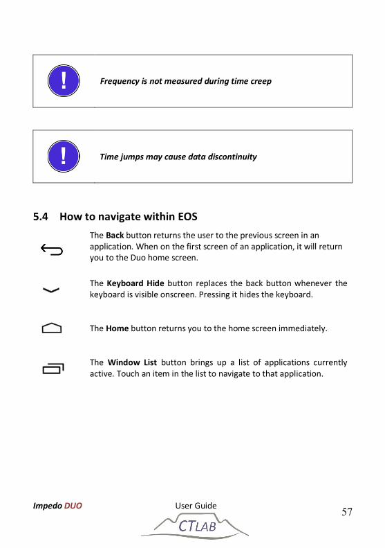
Frequency is not measured during time creep
Time jumps may cause data discontinuity
5.4 How to navigate within EOS
The Back button returns the user to the previous screen in an application. When on the first screen of an application, it will return you to the Duo home screen.
The Keyboard Hide button replaces the back button whenever the keyboard is visible onscreen. Pressing it hides the keyboard.
The Home button returns you to the home screen immediately.
The Window List button brings up a list of applications currently active. Touch an item in the list to navigate to that application.
Impedo DUO User Guide 58
The Power button. Touching the power button will lock the instrument and will display the unlock screen. Within a few seconds after the unlock screen was displayed, the main display will be shut down to save power.
To power down the entire instrument, the user must touch and hold the power button. A ‘Power Off’ window will pop up to ask the user to confirm powering the instrument down. Pressing the OK button will power the instrument down.
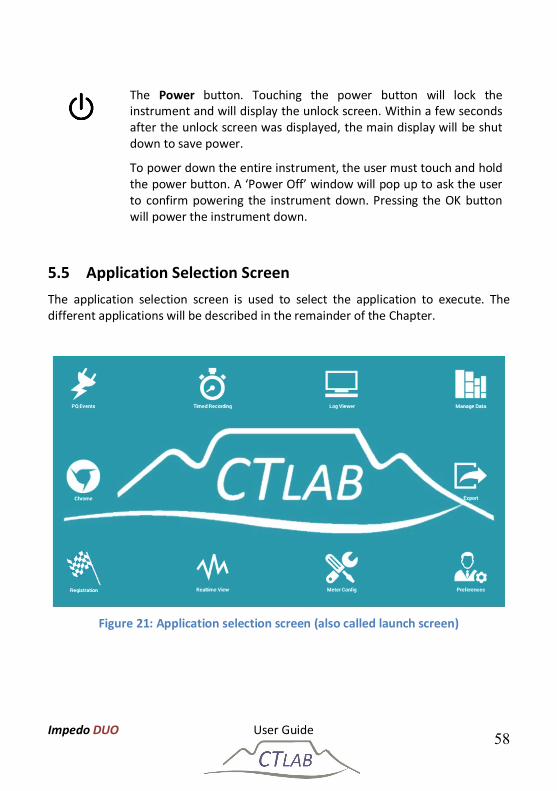
5.5 Application Selection Screen The application selection screen is used to select the application to execute. The different applications will be described in the remainder of the Chapter.
Figure 21: Application selection screen (also called launch screen)
Impedo DUO User Guide 59
5.6 Registration
Figure 22: Registration is used to enrol the instrument as part of a fleet
5.6.1 Account
The instrument is part of a fleet that is registered with Osprey Pro. Enter the account code and password to enrol the instrument.
5.6.2 Standalone
The instrument is not configured as part of an enterprise fleet – the instrument will not attempt to establish communication with an enterprise server. The user can enter the fleet password to enrol it in a standalone fleet.
The instrument’s UI can be secured against tampering by entering a lock screen password. See Section 5.7.3.4 for more detail on password protection on the Impedo Duo.
5.6.3 Osprey Pro (Enterprise)
The instrument is configured as part of an enterprise fleet managed by Osprey Pro. Enter the IP address of the Osprey Pro server and the fleet password.
Impedo DUO User Guide 60
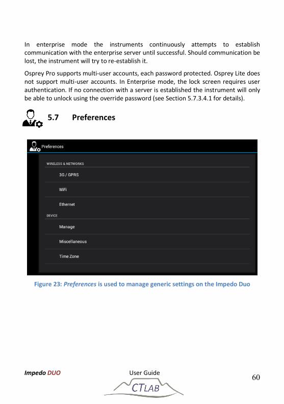
In enterprise mode the instruments continuously attempts to establish communication with the enterprise server until successful. Should communication be lost, the instrument will try to re-establish it.
Osprey Pro supports multi-user accounts, each password protected. Osprey Lite does not support multi-user accounts. In Enterprise mode, the lock screen requires user authentication. If no connection with a server is established the instrument will only be able to unlock using the override password (see Section 5.7.3.4.1 for details).
5.7 Preferences
Figure 23: Preferences is used to manage generic settings on the Impedo Duo
Impedo DUO User Guide 61
5.7.1 Ethernet
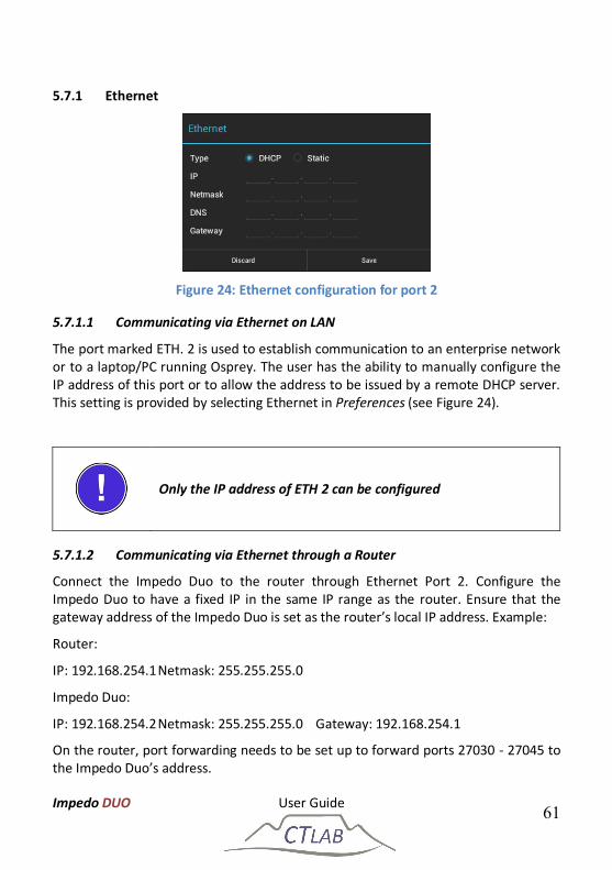
Figure 24: Ethernet configuration for port 2
5.7.1.1 Communicating via Ethernet on LAN
The port marked ETH. 2 is used to establish communication to an enterprise network or to a laptop/PC running Osprey. The user has the ability to manually configure the IP address of this port or to allow the address to be issued by a remote DHCP server. This setting is provided by selecting Ethernet in Preferences (see Figure 24).
Only the IP address of ETH 2 can be configured
5.7.1.2 Communicating via Ethernet through a Router
Connect the Impedo Duo to the router through Ethernet Port 2. Configure the Impedo Duo to have a fixed IP in the same IP range as the router. Ensure that the gateway address of the Impedo Duo is set as the router’s local IP address. Example:
On the router, port forwarding needs to be set up to forward ports 27030 - 27045 to the Impedo Duo’s address.
Impedo DUO User Guide 62
5.7.1.3 Communicating directly with a laptop or PC
The port marked ETH. 1 is used to create a local network. The Impedo Duo will issue DHCP addresses on this port. This port is primarily used to establish communication to a Laptop/PC that is not connected to an enterprise network. This means the laptop/PC needs to be setup to receive its IP configuration through DHCP.
Clicking Discover on the Address Book page of the Osprey software connects the instrument and the laptop without requiring any IP information.
The Impedo Duo serves as a DHCP server on ETH 1
Do not connect Ethernet port 1 to a network with an active DHCP server, as this may cause the network to stop functioning properly
The IP address of Ethernet port 1 is fixed at 192.168.7.1
Impedo DUO User Guide 63
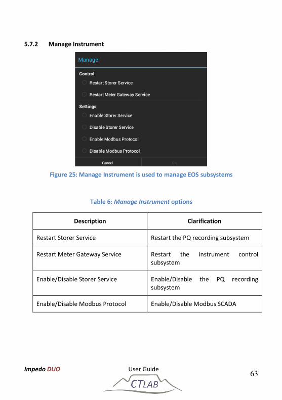
5.7.2 Manage Instrument
Figure 25: Manage Instrument is used to manage EOS subsystems
Table 6: Manage Instrument options
Description Clarification
Restart Storer Service Restart the PQ recording subsystem
Restart Meter Gateway Service Restart the instrument control subsystem
Enable/Disable Storer Service Enable/Disable the PQ recording subsystem
While the Storer service is disabled, no PQ data will be recorded
Disable Modbus if not required, as this subsystem requires more power to operate and will drain the battery faster when no external power is available
5.7.3 Miscellaneous
5.7.3.1 Space Reclaimer
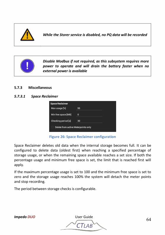
Figure 26: Space Reclaimer configuration
Space Reclaimer deletes old data when the internal storage becomes full. It can be configured to delete data (oldest first) when reaching a specified percentage of storage usage, or when the remaining space available reaches a set size. If both the percentage usage and minimum free space is set, the limit that is reached first will apply.
If the maximum percentage usage is set to 100 and the minimum free space is set to zero and the storage usage reaches 100% the system will detach the meter points and stop recording.
The period between storage checks is configurable.
Impedo DUO User Guide 65
5.7.3.2 Health Shutdown
Figure 27: Health-Manager configuration
Health-Manager periodically checks the system health. The battery charge level and system temperature is shown on the OLED display. Health-Manager will shut down the instrument to protect it from damage if the system temperature drops below 0 ⁰C or rises above 75 ⁰C. Health-Manager will shut down the instrument to protect the battery from damage if the battery charge level drops below 0 %. Uncheck the Enable checkbox (see Figure 27) to instruct Health-Manager to disregard the system health.
Disabling Health-Manager may cause permanent damage to the instrument should a health-based shutdown be indicated
5.7.3.3 Time
Figure 28: Time-Master configuration
The Impedo Duo will not record any PQ data unless it has valid time. Time-Master manages this aspect of the instrument. It automatically determines the best time source. It will use the following sources in order of preference: GPS, Network time, internal clock. Automatic time source selection can be disabled by setting the time source explicitly to either GPS or NTP.
Impedo DUO User Guide 66
Time-Master will query pool.ntp.org to find the best NTP server close to the instrument. If a specific NTP server is desired, the server IP address or DNS name can be entered in the Custom server field (see Figure 28).
The Impedo Duo will not record any PQ data until it has valid time
5.7.3.4 Security
Figure 29: Security configuration
5.7.3.4.1 Override Password
The override password is used to override a user login password (applicable when the instrument was registered as part of an enterprise or Osprey Pro fleet). It can also override the write password. By default it is set as CT Lab.
The default override password is CT Lab
Set the default override password to secure the device against unauthorized physical access
Impedo DUO User Guide 67
5.7.3.4.2 Write Password
If set, applications that perform state changing actions (Preferences, Registration, Meter Config, Manage Data) will require this password before opening. This password can be used when the instrument is in Standalone mode, and it is required that data may be viewed, but no changes made to the instrument. By default it is empty.
5.7.3.4.3 Modbus Password
The Modbus subsystem uses this password during authentication.
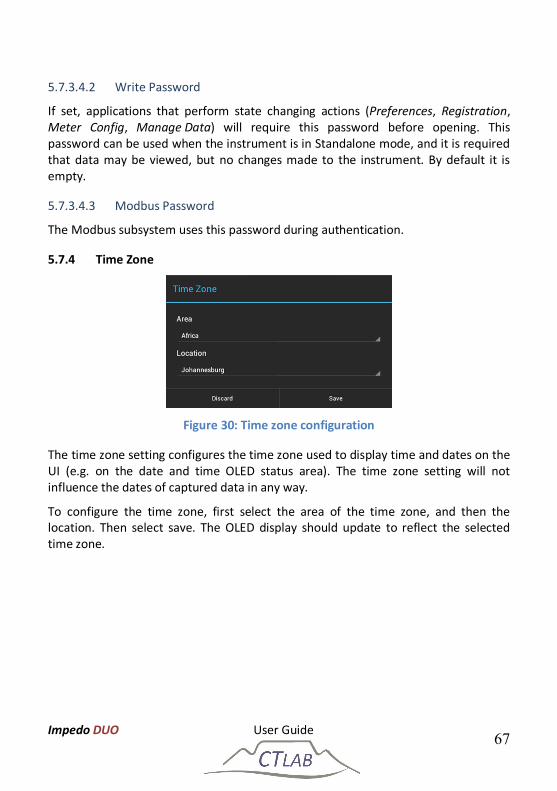
5.7.4 Time Zone
Figure 30: Time zone configuration
The time zone setting configures the time zone used to display time and dates on the UI (e.g. on the date and time OLED status area). The time zone setting will not influence the dates of captured data in any way.
To configure the time zone, first select the area of the time zone, and then the location. Then select save. The OLED display should update to reflect the selected time zone.
Impedo DUO User Guide 68
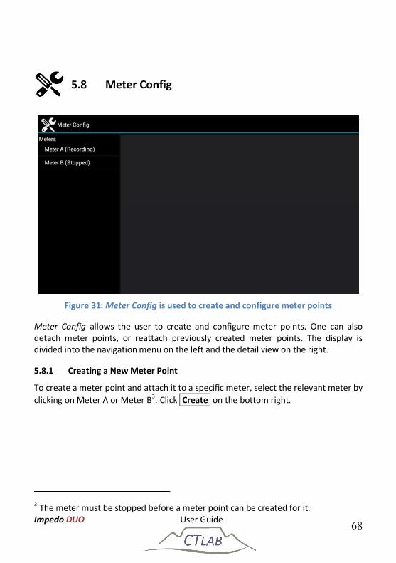
5.8 Meter Config
Figure 31: Meter Config is used to create and configure meter points
Meter Config allows the user to create and configure meter points. One can also detach meter points, or reattach previously created meter points. The display is divided into the navigation menu on the left and the detail view on the right.
5.8.1 Creating a New Meter Point
To create a meter point and attach it to a specific meter, select the relevant meter by clicking on Meter A or Meter B3. Click Create on the bottom right.
3 The meter must be stopped before a meter point can be created for it.
Impedo DUO User Guide 69
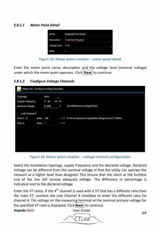
5.8.1.1 Meter Point Detail
Figure 32: Meter point creation – meter point detail
Enter the meter point name, description and the voltage level (nominal voltage) under which the meter point operates. Click Next to continue.
5.8.1.2 Configure Voltage Channels
Figure 33: Meter point creation – voltage channel configuration
Select the installation topology, supply frequency and the declared voltage. Declared Voltage can be different from the nominal voltage in that the utility can operate the network at a higher level than designed. This ensure that the client at the furthest end of the line still receive adequate voltage. The difference in percentage is indicated next to the declared voltage.
Enter the VT ratios. If the 4th channel is used with a VT that has a different ratio than the main VT, uncheck the Link Channel 4 checkbox to enter the different ratio for channel 4. The voltage on the measuring terminal at the nominal primary voltage for the specified VT ratio is displayed. Click Next to continue.
Impedo DUO User Guide 70
It is possible to change between Star (four-wire) and delta (three-wire) topology if the neutral is connected to Vcom
5.8.1.3 Configure Current Channels
Figure 34: Meter point creation – current channel configuration
Check the Enable checkbox to enable current data recording. Select the sensor type used to measure the current. This should correspond with the physical connections of the chosen sensor type to the instrument. Enter the CT ratio. If channel 4 uses a transducer with a different ratio than the rest, uncheck the Link Channel 4 checkbox to enter the different ratio for channel 4. The Impedo Duo allows the derivation of a current channel by applying Kirchhoff's Current Law. If a channel is to be derived, select the appropriate derivation method. Click Next to continue.
It is possible to use a different sensor type on channel 4 than channels 1-3
Impedo DUO User Guide 71
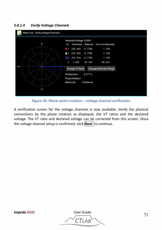
5.8.1.4 Verify Voltage Channels
Figure 35: Meter point creation – voltage channel verification
A verification screen for the voltage channels is now available. Verify the physical connections by the phase rotation as displayed, the VT ratios and the declared voltage. The VT ratio and declared voltage can be corrected from this screen. Once the voltage channel setup is confirmed, click Next to continue.
Impedo DUO User Guide 72
5.8.1.5 Verify Current Channels
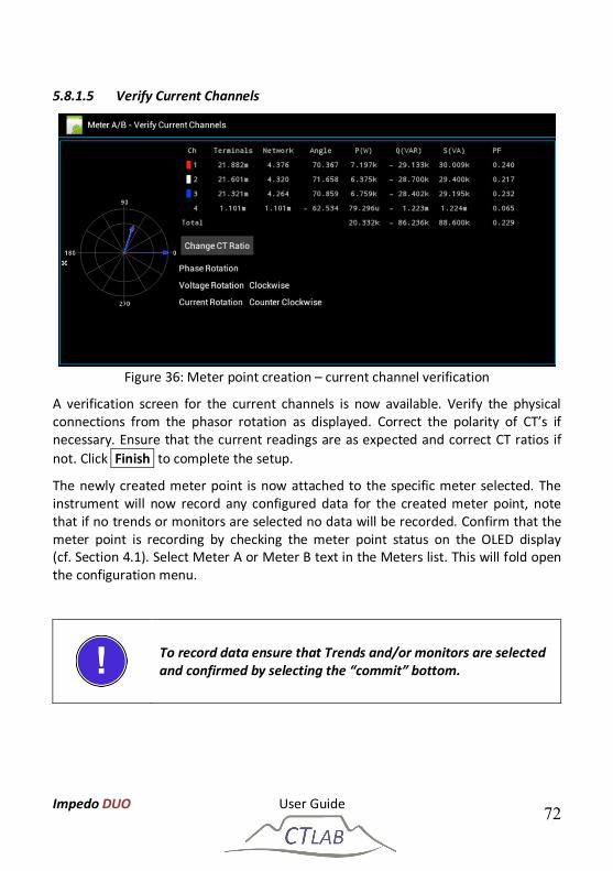
Figure 36: Meter point creation – current channel verification
A verification screen for the current channels is now available. Verify the physical connections from the phasor rotation as displayed. Correct the polarity of CT’s if necessary. Ensure that the current readings are as expected and correct CT ratios if not. Click Finish to complete the setup.
The newly created meter point is now attached to the specific meter selected. The instrument will now record any configured data for the created meter point, note that if no trends or monitors are selected no data will be recorded. Confirm that the meter point is recording by checking the meter point status on the OLED display (cf. Section 4.1). Select Meter A or Meter B text in the Meters list. This will fold open the configuration menu.
To record data ensure that Trends and/or monitors are selected and confirmed by selecting the “commit” bottom.
Impedo DUO User Guide 73
5.8.2 Detaching a Meter Point
Figure 37: Detaching and editing a meter point
When a meter should no longer record data, the meter point can be detached from the meter. To detach a meter point, select the meter in the navigation menu4. This will display detail about the meter point. Click Detach to detach the meter and confirm the action. Confirm that the meter point was detached by checking the meter point status on the OLED display (cf. Section 4.1).
5.8.3 Editing a Meter Point
To edit a meter point, select the recording meter point the navigation menu. Click Edit , and follow the steps as for meter point creation in Section 5.8.1.
4 The meter’s current state must be “Recording”
Impedo DUO User Guide 74
5.8.4 Attaching a Previously Created and Configured Meter Point
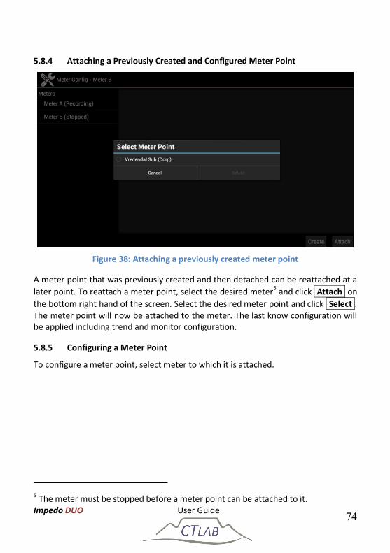
Figure 38: Attaching a previously created meter point
A meter point that was previously created and then detached can be reattached at a later point. To reattach a meter point, select the desired meter5 and click Attach on the bottom right hand of the screen. Select the desired meter point and click Select . The meter point will now be attached to the meter. The last know configuration will be applied including trend and monitor configuration.
5.8.5 Configuring a Meter Point
To configure a meter point, select meter to which it is attached.
5 The meter must be stopped before a meter point can be attached to it.
Impedo DUO User Guide 75
5.8.5.1 Trend configuration
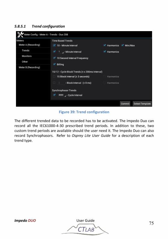
Figure 39: Trend configuration
The different trended data to be recorded has to be activated. The Impedo Duo can record all the IEC61000-4-30 prescribed trend periods. In addition to these, two custom trend periods are available should the user need it. The Impedo Duo can also record Synchrophasors. Refer to Osprey Lite User Guide for a description of each trend type.
Impedo DUO User Guide 76
5.8.5.2 Monitors
Figure 40: Monitor configuration
Monitors are devices used to recognise network events and record diagnostic data when such events occur. To configure monitors on the Impedo Duo, select the appropriate meter and then select Monitors. When a desired monitor is checked, a monitor-specific dialog is presented to configure the monitor. The list of monitors are more than can fit on the display. Sliding one’s finger vertically up or down over the list of monitors scrolls the list up or down, respectively. Refer to Osprey Lite User Guide for a description of each event type and its configuration parameters.
5.8.5.3 Other
The Impedo Duo records waveforms as part of the diagnostic data captured by the monitors or a timed recording. The default sampling rate (retained samples) is the highest option of one samples every 20µs. To conserve storage space and/or bandwidth costs, applying a subsample rate can reduce the sampling rate. This setting will only affect the diagnostic waveform data stored, not any statistics calculated for the event.
Impedo DUO User Guide 77
5.8.5.4 Commit
Once all settings in all sections have been set – click Commit to apply the configuration to the meter. An information box will pop up to inform the user that the new configuration was committed.
Configuration is only applied after pressing Commit - an information box will inform the user of a successful configuration change
5.8.5.5 Predefined Templates
The Impedo Duo comes preloaded with specific measuring templates. To apply a template, select the meter point, and then either Trends or Monitors. Click Select Template and select the desired template. Press Apply to apply the template to the configuration. To effect the configuration, press Commit . An information box will pop up to inform the user that the new configuration was committed.
Impedo DUO User Guide 78
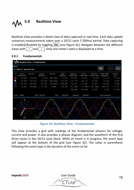
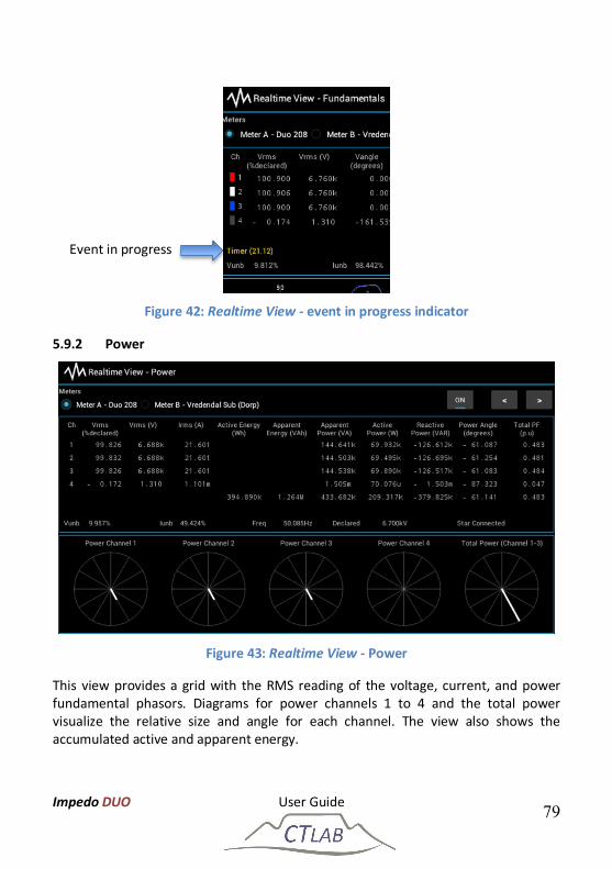
5.9 Realtime View
Realtime View provides a detail view of data captured in real-time. Each data update comprises measurements taken over a 10/12 cycle (~200ms) period. Data capturing is enabled/disabled by toggling On (see Figure 41). Navigate between the different views with > and < . Only one meter’s data is displayed at a time.
5.9.1 Fundamentals
Figure 41: Realtime View - Fundamentals
This view provides a grid with readings of the fundamental phasors for voltage, current and power. It also provides a phasor diagram, and the waveform of the first three cycles in the 10/12 cycle block. While an event is in progress, the event type will appear at the bottom of the grid (see Figure 42). The value in parenthesis following the event type is the duration of the event so far.
Impedo DUO User Guide 79
Figure 42: Realtime View - event in progress indicator
5.9.2 Power
Figure 43: Realtime View - Power
This view provides a grid with the RMS reading of the voltage, current, and power fundamental phasors. Diagrams for power channels 1 to 4 and the total power visualize the relative size and angle for each channel. The view also shows the accumulated active and apparent energy.
Event in progress
Impedo DUO User Guide 80
5.9.3 Harmonics
Figure 44: Realtime View - Harmonics
This view provides a grid with RMS information for a specific harmonic as well as THD for voltage and current. Select the desired harmonic by pressing on the harmonic number drop-down. Select between harmonic and inter-harmonic readings by pressing on the Harmonic drop-down.
The spectrum up to the 49th harmonic for the selected spectrum parameter is visualized at the bottom of the view. The user has a choice between voltage, current, active power, reactive power, and apparent power spectrums.
Impedo DUO User Guide 81
5.10 PQ Events
Figure 45: PQ Events provides a simple list of PQ events
PQ Events allows the user to browse a very simple list of events captured by the instrument. These events are not classified to any specific standard. Classification is done offline with the Osprey Software. Select the meter point for which the event list must be shown. Select the date from which to query as well as the duration (in days). Click Load to load the list of events. The list can be scrolled up and down by sliding one’s finger vertically across the display.
Impedo DUO User Guide 82
5.11 Log Viewer
Figure 46: Log Viewer provides a view on the system event log
Log Viewer is used to browse the system event log. This is a diagnostic log that provides insight into the workings of the internal subsystems. Select the date and time from which to query and then the duration in days, hours, and minutes. Click Load Events to load the list of log events. The list can be scrolled up and down by sliding one’s finger vertically across the display.
Impedo DUO User Guide 83
5.12 Timed Recording
Figure 47: Timed Recording application
Timed Recording provides a mechanism to record detail diagnostic data at a specified time. Select the meter point for which the recording must be made. Choose between starting to record immediately or starting at a scheduled time. Select the recording duration (< 1 minute). Recordings can be repeated with a specified interval. The interval must be at least as long as the recording duration. Finally, select the types of data that must be captured by the recording and press Commit . While the recording is in progress Realtime View will display the event type as “Timer”. A scheduled recording or a recording in progress can be cancelled by pressing Stop . Scheduling a new recording will overwrite a previously scheduled one.
Impedo DUO User Guide 84
5.13 Export
Figure 48: Export allows the user to export data to a USB stick
Data captured on the Impedo Duo can be exported to a USB device using Export. Plug a FAT32 formatted USB device into either USB port 1 or 2. Select the desired USB device from the drop-down. If the device was used to export data before, the last export date will be shown. If the device was not used before, the date will show as N/A (not available). The user may choose to export all data, or export from a specific date. Click Export to start the export process. A dialog will appear showing the progress of the export. The export can be safely aborted, and the data exported up to that point will be on the USB device. The user can select which harmonics to export from the harmonic selection tab (see Figure 49). This selection is persisted to the USB device and will be used when the device is plugged into the Impedo Duo on a next occasion. Exporting data using this method is a slow process – exporting an entire 100% filled storage chunk will take several hours.
Should the user wish to use a mass storage device, the instrument can be configured to continually export data to the mass storage plugged at one of the USB ports. The “Continue Export” option will only be available after exporting some data to the mass storage.
Impedo DUO User Guide 85
Figure 49: Export - harmonic selection
Impedo DUO User Guide 86
5.14 Manage Data
Figure 50: Manage Data provides manual data management options
The Impedo Duo manages its internal storage using Space Reclaimer (see Section 5.7.3.1). Manage Data provides the user with the manual data management options as described in Table 6. Select the desired option and press Delete .
Table 7: Manage Data delete options
Description Clarification
Delete all meter points and associated data
All meter points, and their data including configurations will be deleted
Delete meter point and associated data The specified meter point, including its data and configurations will be deleted. Other meter points will not be deleted
Delete segment Only the specified data segment for the specified meter point will be deleted
Delete data range Only data within the specified date range for the specified meter point will be deleted
Impedo DUO User Guide 87
Delete data for all meter points Delete all data, but no configuration Delete data for meter point Delete all date for the specified meter
point, but keep the meter point and its configuration
Manage Data also allows the user to return the instrument to its factory settings. All meter points, data, and instrument settings such as passwords, time zone, and Space Reclaimer configuration will be deleted. After a factory reset the instrument will reboot. Press Reset Instrument to reset the instrument to its factory default.
The File Info tab provides internal storage usage information (see Figure 51).
Reset Instrument will delete all PQ data captured to date, as well as all instrument configuration settings from the device
Reset Instrument will reboot the device once to complete the reset process
Figure 51: Manage Data – File Info
Impedo DUO User Guide 88
6 Impedo Duo Installation
6.1 Mounting the Impedo Duo
6.1.1 Panel Mounting Installation
Installation components:
a) Back Plate: The plate with the bigger cavity of the two and four drilled holes as shown in Figure 52.
b) Front Plate: The plate with the smaller cavity of the two plates and eight drilled holes as shown in Figure 53.
c) Four mounting screws and four holding screws as shown in Figure 54.
Figure 52: The back plate with the bigger cavity of the two, and four drilled holes
Figure 53: The front plate with the smaller cavity of the two plates, and eight
drilled holes
Impedo DUO User Guide 89
Figure 54: Four mounting and holding screws
Step 1:
Fit the back plate6 (see Figure 52) on the panel door where the instrument should be installed, mark the inside cavity and mounting holes on the panel door.
Step 2:
Cut the marked cavity into the panel door and drill the mounting holes as shown in Figure 55.
Figure 55: Panel door with cut-out
6 Optional accessory
Mounting Screw
Holding Screw
Impedo DUO User Guide 90
Step 3:
Install the front and back plates on the panel door using the mounting screws as shown in Figure 54.
Step 4:
Fit the Impedo Duo into the installation plates and screw the holding screws into the Impedo Duo.
6.1.2 19” Rack Mounting Installation
A 19” rack (4U) stainless steel mounting plate carry the Impedo Duo while providing a mechanical interface for 19” racks7.
Figure 56: 19’’ rack with Impedo Duo
7 Optional accessory
Impedo DUO User Guide 91
6.1.3 Portable version
The ImpedoDUO can also be supplied as a portable unit for PQ investigations as shown in Figure 57. The accessories included in the portable unit are listed in Table 8.
Figure 57: Impedo DUO portable unit
Table 8: List of accessories
Accessory description Qty.
Portable Impedo DUO case 1
GPS antenna + 15m extension cable 1
Power Connection set 1
Voltage connection set (Wiring and six clips included)
2
Current sensor and current transducer connection set
2
US Current Clamp 250/500/1000:5A 6
Micro Clamps 5A:1V 6
Impedo DUO User Guide 92
6.2 Connections
6.2.1 AC Power
Always connect the safety earth terminal located on the power connector first!
Table 9 and Figure 58 depict how to connect the AC power supply.
Table 9: AC power connection layout
Terminal Legend Description
1. L Live Terminal
2. E Safety Earth
3. N Neutral Terminal
Figure 58: Impedo Duo AC power supply connection
Neutral
Earth
Live
Impedo DUO User Guide 93
6.2.2 Power Over Ethernet (PoE)
In addition to, or as alternative to AC power, the instrument can be powered via any of the Ethernet ports using an IEEE 802.3-2008 compliant power source.
6.2.3 Instrument Activation
The instrument is shipped with the reset switch switched off to protect the battery and increase the storage live of the Impedo DUO. The reset switch is reachable via a small hole close to the GPS port on the right side of the instrument as shown below.
Figure 59: Impedo DUO reset button
If power is connect to the instrument and the reset button is pressed the Power switch icon can be slide down as shown below.
Figure 60: Power switch icon on the OLED
Impedo DUO User Guide 94
6.2.4 Voltage connections
6.2.4.1 Single phase connection
Always connect the safety earth terminal located on the power connector first!
Table 10: VT circuit connection layout for single phase connection
Terminal Legend 110V VT Circuit or 400V/550V Star (4-wire) Systems
1. V1 Phase Voltage
2. V2 Open
3. V3 Open
4. Vcom Neutral
5. V4+ Earth
6. V4- Neutral
Connect the phase Voltage to Voltage Inputs 1 as shown in Figure 61. Connect Neutral (400 V systems) or the star-point (110 V VT circuits) to Vcom. The fourth voltage input may be used to measure Neutral-Earth voltage.
Figure 61: Impedo DUO single-phase connection
Phase 1
Phase 4 Ref
Phase 4
Neutral
Impedo DUO User Guide 95
6.2.4.2 110 V Voltage Transformer (VT) Circuits & 400V Direct (Star/ 4-wire systems)
Always connect the safety earth terminal located on the power connector first!
Table 11: VT circuit connection layout for 4-wire star connection
Terminal Legend 110V VT Circuit or 400V/550V Star (4-wire) Systems
1. V1 Phase 1
2. V2 Phase 2
3. V3 Phase 3
4. Vcom Neutral (Star connection point)
5. V4+ Earth (optional for 400V systems only)
6. V4- Star connection point (Neutral) (Optional for 400V systems only)
Connect Phase 1,2 and 3 to Voltage Inputs 1-3 as shown in Figure 62 below. Connect Neutral (400V systems) or the star-point (110V VT circuits) to Vcom. The fourth voltage input may be used on 400V systems to measure Neutral-
Earth voltage.
Figure 62: Impedo Duo 4-wire star connection
Phase 3
Phase 2
Phase 1
Phase 4 Ref
Phase 4
Neutral
Impedo DUO User Guide 96
Meter A and B are not conformed to specifically measure single phase, 4-wire (Star) or 3-wire (Delta) but rather handle all topologies.
Impedo DUO User Guide 97
6.2.4.3 110V Voltage Transformer (VT) Circuits or 400V/550V Direct (Delta/3-wire systems)
Always connect the safety earth terminal located on the power connector first!
Table 12: VT circuit connection layout for 3-wire delta connection
Terminal Legend 110V VT Circuit or 400V/550V Delta (3-wire) Systems
1. V1 Phase 1
2. V2 Phase 2
3. V3 Phase 3
4. Vcom Open (Note: Vcom may also be connected to the earthed Phase/Phase 2 on 110V VT circuits)
5. V4+ Open
6. V4- Open
1) Connect Phase 1,2 and 3 to Voltage Inputs 1-3 as shown in the Figure 60. 2) Leave Vcom open or connect Vcom to the earthed Phase (Phase 2) on 110V VT
circuits.
Figure 63: Impedo Duo 3-wire delta connection
Phase 3
Phase 2
Phase 1
Impedo DUO User Guide 98
Meter A and B are not conformed to specifically measure single phase, 4-wire (Star) or 3-wire (Delta) but rather handle all topologies.
Impedo DUO User Guide 99
6.2.5 Current connections
6.2.5.1 Direct (1A/5A Current Transformer (CT) Circuits)
6.2.5.1.1 Single phase connection
The Impedo DUO can interface with 1 A or 5 A CT circuits and has a peak long-term current withstand of 6 A and 50 A for 3 seconds.
Table 13: CT circuit connection layout
Terminal Legend Description
1. I1+ Phase 1 Current Input
2. I1- Phase 1 Current Return
3. I2+ None
4. I2- None
5. I3+ None
6. I3- None
7. I4+ None
8. I4- None
Figure 64: CT circuit connection layout
Phas
e 1
Retu
rn
Phas
e 1
Impedo DUO User Guide 100
6.2.5.1.2 Three phase connection
Table 14: CT circuit connection layout
Terminal Legend Description
1. I1+ Phase 1 Current Input
2. I1- Phase 1 Current Return
3. I2+ Phase 2 Current Input
4. I2- Phase 2 Current Return
5. I3+ Phase 3 Current Input
6. I3- Phase 3 Current Return
7. I4+ Phase 4 Current Input
8. I4- Phase 4 Current Return
Figure 65: CT circuit connection layout
The Duo can be configured to derive the Neutral current by the summation of the 3 line currents in star connected (4-wire) circuits.
The Duo can be programmed to derive any one of the missing line currents by the summation of the other 2 currents in Delta connected (3-wire) circuits
Phase 3
Phase 2
Phase 1
Phase 4 Return
Phase 4
Phase 1 Return
Phase 2 Return
Phase 3 Return
Impedo DUO User Guide 101
6.2.5.2 Current Transducer Connections
6.2.5.2.1 Single phase connection
The current transducer inputs on the Impedo DUO have a peak voltage input range of 2 V (1.4 VRMS).
Table 15: Current transducer sensor connection layout
Terminal Legend 1 V Output Current Transducer Circuits
1. V1+ Voltage 1
2. V1- Voltage 1 Reference
3. V2+ None
4. V2- None
5. V3+ None
6. V3- None
7. V4+ None
8. V4- None
Figure 66: Current Transducer circuit connection layout
Phase 1 Phase 1 Ref
Impedo DUO User Guide 102
6.2.5.2.2 Three phase connection with neutral / return
The current transducer inputs on the Impedo DUO has a peak voltage input range of 2 V (1.4 VRMS).
Table 16: Current transducer sensor connection layout
Terminal Legend 1V Output Current Transducer Circuits
1. V1+ Voltage 1
2. V1- Voltage 1 Reference
3. V2+ Voltage 2
4. V2- Voltage 2 Reference
5. V3+ Voltage 3
6. V3- Voltage 3 Reference
7. V4+ Voltage 4
8. V4- Voltage 4 Reference
Figure 67: CT circuit connection layout
Phase 2 Ref Phase 3 Ref Phase 4 Ref
Phase 1 Phase 1 Ref
Phase 4
Phase 3
Phase 2
Impedo DUO User Guide 103
The Impedo DUO can be configured to:
Derive the Neutral current by the summation of the 3 line currents in star connected (4-wire) circuits.
Derive any one of the missing line currents by the summation of the other 2 currents in Delta connected (3-wire) circuits.
6.2.6 Ethernet Based Communication
See Section 0 and 0 for details.
6.2.7 GPS
A GPS antenna can be connected to the instrument. The GPS provides accurate time and location information to the instrument. See Section 0 for details.
6.2.8 3G / GPRS Modem
The Impedo Duo supports communication via a USB modem. Connect the modem to USB port 1 and use the GUI to configure the communication. Contact CT Lab for more information.
Impedo DUO User Guide 104
7 Maintenance The Impedo Duo is designed to be a very low maintenance device that can operate unattended for years at end. It contains no user-replaceable parts.
7.1 Battery The internal LiFePO4 battery powers the instrument in the absence of power. This battery guarantees 2,000 charge/discharge cycles. If cycled once per day, it translates to a 5-year life expectancy. The battery is charged when external power is applied to the AC power supply, or the instrument is connected to an IEEE 802.3-2008 compliant POE source via either of its Ethernet ports.
7.2 Display To clean the Impedo DUO screen, never use any type of cleaning solvent such as Windex or similar chemical products. Use only water. Ideally, use water with a lint free scratch resistant cloth (microfiber is best) to clean the Impedo DUO screen by dampening the cloth slightly. Then clean the screen using soft, even strokes.
7.3 Transport Should the instrument be couriered or shipped please follow these instructions:
1. Insert the instrument into a plastic bag to prevent water damage during shipment transit; and
2. Protect the instrument properly and also put it inside a padded box to prevent mechanical damage during transit.
Or
Use the CT Lab packaging in which the instrument was supplied.
7.4 Storage To prevent damage to the Impedo DUO battery the instrument should always be stored in the Powered Down state. When the instrument is powered down the instrument can be stored for up to 5 years.
Instrument Power Down:
1. Hold the ON/OFF button down for 3 seconds; then
Impedo DUO User Guide 105
2. Switch the Reset Button off with a paperclip see Figure 59. The instrument is powered when the switch is in the depressed state.
Note that removing power from the instrument also removes power from the RTC. Upon start-up after a power cycle the RTC is in an unknown state and the instrument must first be connected to a valid time source (GPS or NTP) to ensure it time-stamps data correctly.
7.5 Warrantee and Repair
7.5.1 Warrantee Statement
CT Lab (Pty.) Ltd. warrants its products and parts as set forth below. Please note that this is only applicable if the product is bought directly from CT Lab (Pty.) Ltd. or CT Lab (Pty.) Ltd. accredited resellers.
3. CT Lab (Pty.) Ltd. warrants the ImpedoDUO and Vecto II to be in compliance with their respective specifications under normal use and service, and to be free from material defects in materials and workmanship for a warranty period of twelve (12) months from the date of the installation or eighteen (18) months from the date of shipment, whichever occurs first. The warranty period for new spare parts and components sold by CT Lab (Pty.) Ltd. is twelve (12) months from the date of shipment. The warranty period for repaired or refurbished parts repaired by CT Lab (Pty.) Ltd. is ninety (90) days from the date of shipment, unless repaired pursuant to a warranty, in which case the repair is warranted for the time remaining of the original warranty period.
4. Warrantee repair:
a. If any field device fails during the applicable warranty period CT Lab (Pty.) Ltd. can either repair or replace the Failed Good, provided the Customer (a) returns the product to the location designated by CT Lab (Pty.) Ltd. or accredited resellers within the warranty period; and (b) prepays the freight costs both to and from such location. Customer shall, in all cases, be responsible for the In/Out Costs. If CT Lab (Pty.) Ltd. determines that the returned good is not defective, Customer shall pay and/or reimburse CT Lab (Pty.) Ltd. for all expenses incurred by CT Lab (Pty.) Ltd. in the examination of the returned good.
Impedo DUO User Guide 106
b. Customer’s remedy under the warranty for services shall be, at CT Lab (Pty.) Ltd. sole cost and expense, to correct or re-perform any defective or non-conforming services to assure compliance with the contract requirements.
5. Warranty Exceptions. This General Limited Warranty does not include costs for removal or installation of products, or costs for replacement labor or materials, which are the responsibility of the Customer. The warranties in this General Limited Warranty do not apply to goods that have been: installed improperly or in non-recommended installations; installed to a voltage transformer (VT) or current transformer (CT) that is not functional, or is not in safe operating condition, or is damaged, or is in need of repair; tampered with; modified or repaired with parts or assemblies not certified in writing by CT Lab (Pty.) Ltd., including without limitation, communication parts and assemblies; improperly modified or repaired (including as a result of modifications required by CT Lab (Pty.) Ltd.); converted; altered; damaged; read by equipment not approved by CT Lab (Pty.) Ltd. If CT Lab (Pty.) Ltd. identifies any exceptions during examination, troubleshooting or performing any type of support on behalf of Customer, then Customer shall pay for and/or reimburse CT Lab (Pty.) Ltd. for all expenses incurred by Sensus in examining, troubleshooting, performing support activities, repairing or replacing any Equipment that satisfies any of the Exceptions defined above. The above warranties do not apply in the event of Force Majeure.
15 Thermo Lane, Techno Park, Stellenbosch, South Africa
7.5.4 Repair and Calibration
Should the instrument be returned to CT Lab for repairs please follow these instructions:
1. Insert the instrument into a plastic bag to prevent water damage during shipment transit; and
2. Protect the instrument properly and also put it inside a padded box to prevent mechanical damage during transit.
3. Complete the fault report and sent it and the instrument to CT Lab.
o Notify [email protected], provide details on the instrument and how it was shipped and how it can be tracked and with a copy of the fault report.
The package and instrument remain the responsibility of the client until delivered to CT Lab.
The Impedo DUO stores calibration constants on EEPROM that can never be lost for the live of the IC. All systems in the Impedo DUO are protected against power interruptions and voltage event with an internal LiFePO4 battery that enables the instrument to shut down without damaging any system in the instrument. However, in order to verify that the instrument is measuring correctly, it is recommended to recalibrate the instrument at least once every five years.
The Impedo DUO does not require recalibration. Calibration constants will not change and can never be lost for the live of the product’s EEPROM IC.
Impedo DUO User Guide 108
7.5.1 Disposal
7.5.1.1 EU Countries
The Impedo DUO is subject to the European Directive 2012/19/EU on waste electrical and electronic equipment (WEEE) and the corresponding national legislation. The WEEE Directive outlines the procedure for handling electrical waste equipment across the EU.
The Impedo DUO may not be disposed of with normal waste. Should the instrument reach its end of life, it may be returned to the distributor free of charge. In addition, CT LAB will accept instruments that reached end of life free of charge.
7.5.1.2 Non-EU Countries
The proper disposal of electrical devices prevents the occurrence of any negative effects on people or the environment, follows the specific procedures for handling harmful substances and enables valuable raw materials to be recycled. Therefore, it is recommended that electrical devices are disposed of in a separate, environmentally-friendly waste collection and not with normal waste. In some cases, national legislation also stipulates the separate disposal of electric and electronic products. Please ensure you dispose of electrical devices in accordance with the valid regulations in your country. CT LAB will accept instruments that reached end of life free of charge.
CT LAB will accept instruments that reached end of life free of charge for proper disposal.
Impedo DUO User Guide 109
Appendices
8 Impedo DUO dimensions
Impedo DUO User Guide 110
8.1 Panel mounting plates
8.2 19” installation plate
Impedo DUO User Guide 111
9 Impedo DUO wiring diagram
Impedo DUO User Guide 112
10 Impedo DUO rating plate (Back plat)
SWITCH A
S11S22
S33CM4
SWITCH B
S45S56
S67CM8
V1
+1‒2
V2
+3‒4
V3
+5‒6
V4
+7‒8
I1+1
‒2
I2+3
‒4
I3+5
‒6
I4+7
‒8
V4
8‒7+
V3
6‒5+
V2
4‒3+
V1
2‒1+
I4
8‒7+
I3
6‒5+
I2
4‒3+
I1
2‒1+
V1 1
23
45
6V
2V
3V
REFV
4+V
4-
2E
SIDEB
1L3N
Full Scale Range: 6.0ARM
SFull Scale Range: 600V
RMS
POW
ER SUPPLY
90-300V AC (45-65Hz)100-300V DC30VA (m
ax.)
300V, 0.1A
(max.)
RMS
RMS
Active Antenna3.3V DC, 0.1A (m
ax.)
USB2.0 High Speed Host5V D
C, 0.5A (max.)
CURRENT SENSO
R INPUTS
Full Scale Range: 6.0ARM
S
CURRENT TRANSDU
CERSFull Scale Range: 1.0V
RMS
ETH. 2 w
ww
.ctlab.com
ww
w.pq-portal.com
VOLTAGE SEN
SOR INPU
TS
CTLAB
SWITCH
ED OU
TPUTS
USB 1
GPS
CURRENT TRANSDU
CERSFull Scale Range: 1.0V
RMS
SIDEA
SIDEB
CURRENT SEN
SOR INPU
TSSIDE
A
ETH. 1
V11
23
4V
2V
3V
REF
VOLTAGE SEN
SOR INPU
TSFull Scale Range: 600V
RMS
V4-
V4+
65
Impedo D
uoIEC 61000-4-30-ED
3.0 Class A3-phase Pow
er Quality Recorder
!Refer to the U
ser M
anual for detailed connection diagram
s.
Impedo DUO User Guide 113
11 Portable ImpedoDUO
Impedo DUO User Guide 114
12 Accessories and Options The following are standard options.
Impedo DUO Portable Impedo DUO case GPS antenna + 15m extension cable Power Connection set 2 x Voltage connection set (Wiring and 5 clips included) 2 x Current sensor and current transducer connection set 6 x US Current Clamp 250/500/1000:5A 6 x Micro Clamps 5A:1V
Impedo DUO User Guide 116
Portable case Magnetic GPS antenna 15m extension cable
Voltage connection wiring Voltage connection clips Current connection wiring
US clamps 250/500/1000:5A CT Micro clamps 5A:1V Pic-tails for safe connection to the ImpedoDUO
Impedo DUO User Guide 117
Screw driver USB with meter key Ethernet cable
Impedo DUO User Guide 118
13 Glossary
Instrument – Electronic device, such as the Impedo Duo Meter – Component of an instrument that performs
measuring (the Impedo Duo contains two meters)
Meter Point – The physical measuring point that is measured by a meter
Fleet password – Used to secure communication across a fleet of instruments
Instrument Key – Unique key that is required to authenticate an instrument
Lock Screen – Screen first presented to user upon leaving power saving mode
OLED display – White status display on the right side of the Impedo Duo