On the Sampling and Compression of the Plenoptic Function Pier Luigi Dragotti Imperial College London Joint work with J. Berent (Google), M. Brookes (ICL), A. Gelman (ICL), N. Gehrig (Odus Technologies) C. Gilliam (ICL), J. Pearson (ICL), V.Velisavljevic (Deutsche Telekom).
Transcript
On the Sampling and Compression of the Plenoptic Function
Pier Luigi DragottiImperial College London
Joint work with J. Berent (Google), M. Brookes (ICL), A. Gelman (ICL), N. Gehrig (Odus Technologies) C. Gilliam (ICL), J. Pearson (ICL), V.Velisavljevic (Deutsche Telekom).
Motivation
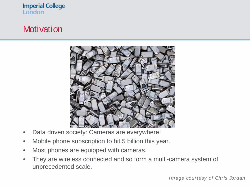
• Data driven society: Cameras are everywhere!• Mobile phone subscription to hit 5 billion this year.• Most phones are equipped with cameras.• They are wireless connected and so form a multi-camera system of
unprecedented scale.
Image courtesy of Chris Jordan
Problem Statement and Motivation
• We can seriously start thinking about 3DTV, free-viewpoint TV, 3D web applications, online virtual visits with viewer interaction, etc.
• There is a need for scalable, fast and unsupervised algorithms that can give the user a photo-realistic ‘being there’ experience
Available images
Problem Statement and Motivation
• We can seriously start thinking about 3DTV, free-viewpoint TV, 3D web applications, online virtual visits with viewer interaction, etc.
• There is a need for scalable, fast and unsupervised algorithms that can give the user a photo-realistic ‘being there’ experience
• This is a classical sampling and interpolation problem
Fill in the gaps and create a walkthrough environment
Talk Outline
1. Structure of the data: The plenoptic function, the EPI and the lightfield2. Parametric sampling of the plenoptic function3. Spectral Analysis of the plenoptic function4. Layer Based Sampling and Interpolation:
1.Plenoptic layers: Extraction and interpolation algorithms2.Adaptive methods
5. Distributed and centralized compression of the plenoptic function6. Conclusions and Outlook
The Plenoptic Function
• “The sole communication link between physical objects and their corresponding images” – Adelson/Bergen
• 7D function that describes the intensity of each light ray that reaches a point in space [AdelsonB:91]
• Assumption can be made to reduce the number of dimensions:• Intensity remains constant unless occluded• 3 channels for RGB• Static scenes• Viewing position constraints
Epipolar Plane Image (EPI)
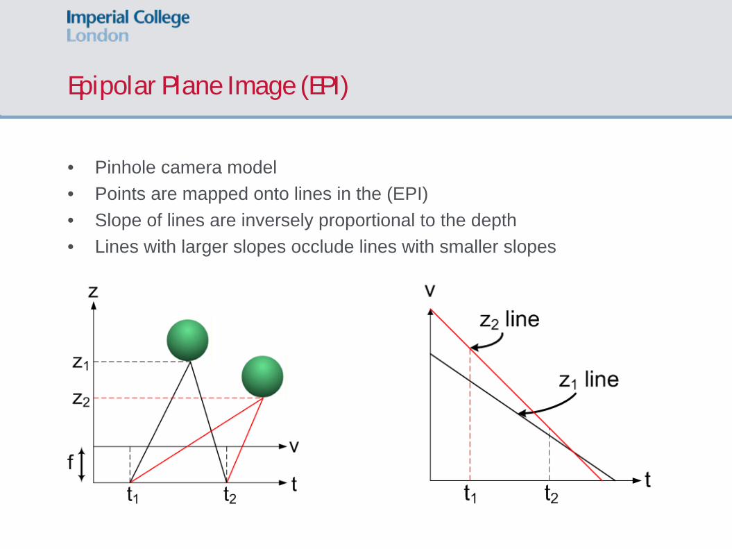
• Pinhole camera model• Points are mapped onto lines in the (EPI)• Slope of lines are inversely proportional to the depth• Lines with larger slopes occlude lines with smaller slopes
Epipolar Plane Image (EPI)
• Pinhole camera model• Points are mapped onto lines in the (EPI)• Slope of lines are inversely proportional to the depth• Lines with larger slopes occlude lines with smaller slopes
EPI Structure
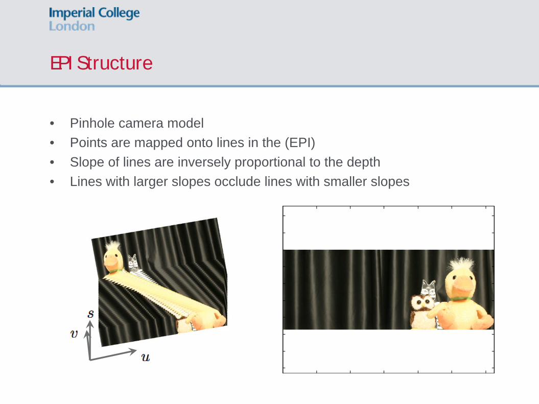
• Pinhole camera model• Points are mapped onto lines in the (EPI)• Slope of lines are inversely proportional to the depth• Lines with larger slopes occlude lines with smaller slopes
The Light Field
• First introduced in [LevoyH96]• Light rays are characterized by their intersection with the camera plane
and the image plane• 4D parameterization of the plenoptic function
Parametric Sampling of the Plenoptic Function [Chebira-D-Sbaiz-Vetterli:03]
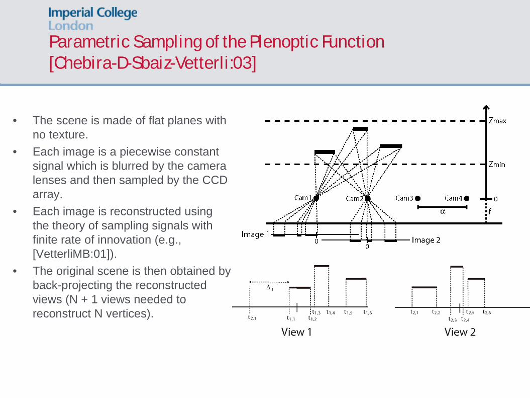
• The scene is made of flat planes with no texture.
• Each image is a piecewise constant signal which is blurred by the camera lenses and then sampled by the CCD array.
• Each image is reconstructed using the theory of sampling signals with finite rate of innovation (e.g., [VetterliMB:01]).
• The original scene is then obtained by back-projecting the reconstructed views (N + 1 views needed to reconstruct N vertices).
Parametric Sampling of the Plenoptic Function (Cont’d)
Observed blurred, low-resolution images
Exact Reconstruction of each view using FRI sampling theories
Parametric Sampling of the Plenoptic Function - Example
Exact Reconstruction of three views
Rendering of any new view
Plenoptic Spectral Analysis
(a) Scene (b) EPI (c) Plenoptic Spectrum
Plenoptic Spectral Analysis
(a) Scene (b) EPI (c) Plenoptic Spectrum
Plenoptic Spectral Analysis
(a) Scene (b) EPI (c) Plenoptic Spectrum
Plenoptic Spectral Analysis
Plenoptic spectrum exactly bound within two lines relating to the minimum and maximum depths of the scene [ChaiCST:00]
Plenoptic Sampling [ChaiCST:00]
(a) Plenoptic Spectrum Sampled in v (b) Plenoptic Spectrum Sampled in t
•Finite camera resolution enforces lowpass filtering in ωv
• Sampling in t of period Δt replicates the Plenoptic spectrum in ωt
The sampling is exact only with an infinite flat plane and Infinite Field of View (FoV)
Slanted Plane Geometry
Set-up:• Finite Field of View (FoV) for the Cameras => • Finite Plane Width• Sinusoidal Texture Signal Pasted to Scene Surface• Lambertian Scene
],[ mm vvv −∈
Slanted Plane Geometry: Effect on the EPI
Slanted Plane Plenoptic Spectrum [GilliamDB:10]
•Lines a=0 and b=0 are related to the maximum and minimum depth•Line c-1=0 is related to the minimum projected frequency captured at −vm
•Line c+1=0 is related to the maximum projected frequency captured at +vm
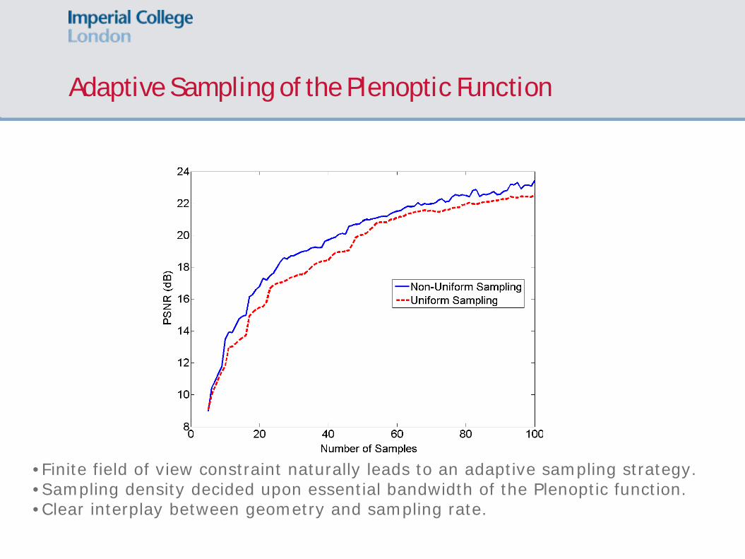
Adaptive Sampling of the Plenoptic Function
•Finite field of view constraint naturally leads to an adaptive sampling strategy.•Sampling density decided upon essential bandwidth of the Plenoptic function.•Clear interplay between geometry and sampling rate.
Linear Interpolation of a Sparse Light Field
Depth Layer Extraction
• Decompose the EPI into layers with similar depths.• Anticipate occlusion ordering in order to make the layers independent
Unsupervised Layer Extraction [BerentDB:09]
1. Input images (3 in this example): 2. Color segmentation of reference image (Mean-Shift):
3. Choose number of depths (i.e. layers):
4. Assign each patch to a layer using a matching function:
Layer boundaries usually occur at color changes
Set of patches
Unsupervised Layer Extraction
5. Generate layers:
6. Run matching with occlusions:
Visibility function for each pixel on a layer:
New matching functional:
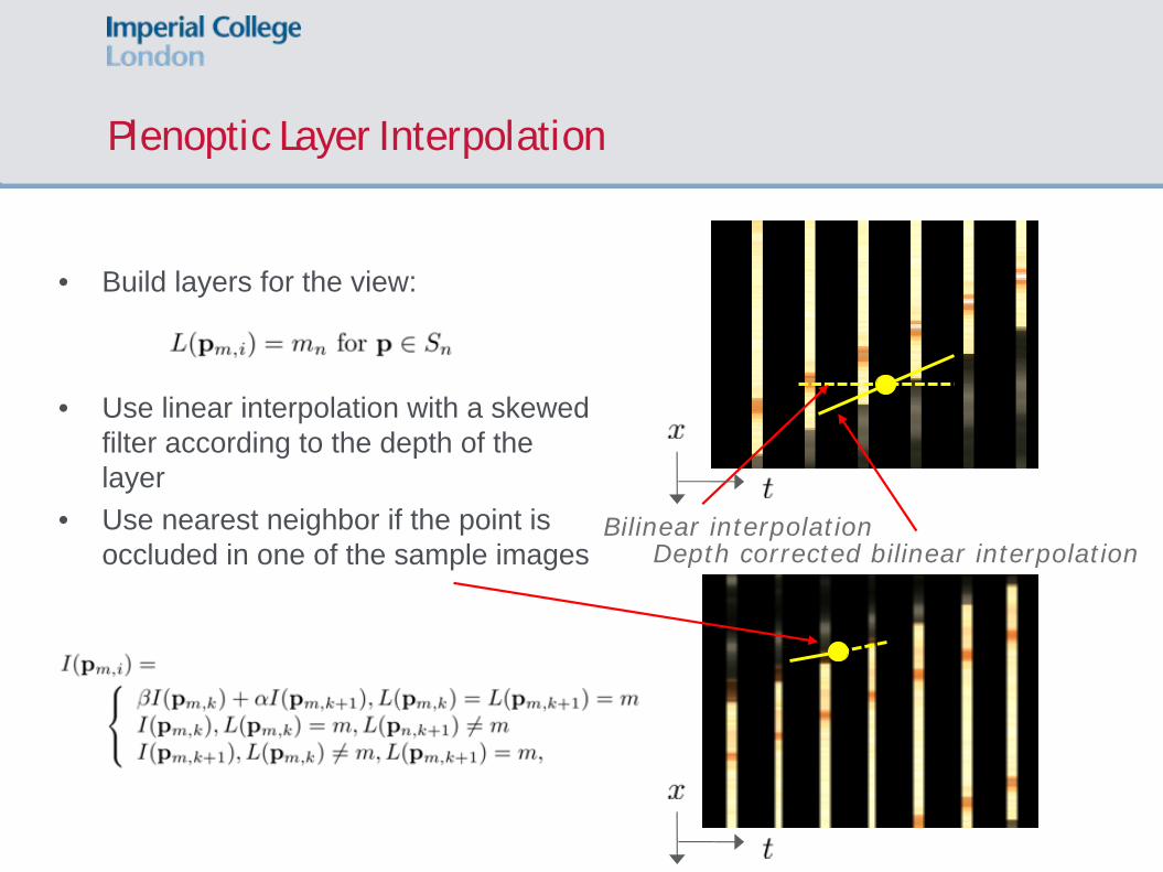
• Build layers for the view:
• Use linear interpolation with a skewed filter according to the depth of the layer
• Use nearest neighbor if the point is occluded in one of the sample images
• We can use layers to reduce aliasing but how many should we use given a set of images?
• Layers slice the spectra into pieces• Each layer has smaller depth variation (i.e. a tighter bow-tie)• Individually render each layer and blend them to create synthesized
view
Adaptive Layer Extraction
Estimated using block matching and outlier rejection
Feed dm to the layer extraction algorithm
• Adaptive rendering system: can use the interplay between complexity - rendering quality - number of images
• Interpolation algorithm can be made to automatically estimate the amount of geometry required in the images and extract layers accordingly.
IBR Results: Rendering Quality versus Layers
M=3 layers SNR 23.49 dB
M=11 layersSNR 27.02 dB
M=30 layersSNR 27.45 dB
Layers:
Synthesized view:
Error:
IBR Results: Rendering Quality versus Layers
Number of layers estimated
IBR Results: Non-uniform arrays
M=5 layers, MS: 2.55 sec, LE: 1.7 sec
M=10 layers, MS: 2.47 sec, LE: 2.48 sec
(Matlab implementation)
IBR Results: Adaptive Layer Extraction
5 Images Acquired 25 Images Rendered
IBR Results on the Lightfield
Demo due to James Pearson (ICL)
Compression of Multi-view Images
•Assume the plenoptic function can be critically sampled with N cameras•Cameras communicate through a (multi-access) channel with capacity C=R bits•What happens when we have M>N cameras but the same channel capacity?
A glimpse at the fundamental interplay between sampling, compression and transmission in multi-camera systems
An exact bit-conservation result for parametric plenoptic functions
Observed blurred, low-resolution images
Assumption:Minimum and maximum depth of the planes is known apriori
Methogology:The vertices of the planes are retrieved exactly at each camera by using FRI samplingThe location of each vertex is quantized and encoded using simple distributed compression schemes (e.g., modulo encoding)
An exact bit-conservation result for parametric plenoptic functions
Modelling Multi-view Images
•Each scan-line of the images is a piecewise smooth signal.•The residual is assumed to be globally smooth.•Compress the first signal independently•Transmit the low-pass coefficients of the second signal together with the less significant bits of the wavelet coefficients.
Modelling Multi-view Images – Simulation Results
•Distributed: PSNR=28.1dB at 0.34bpp•Independent: PSNR=26.5dB at 0.31bpp
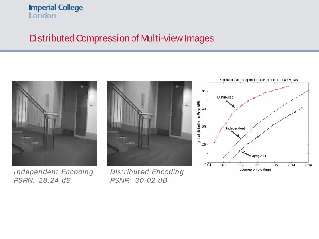
Distributed Compression of Multi-view Images
•Each image is compressed using an algorithm based on quadtree decomposition•Transmit most of the quad-tree structure from each encoder•Transmit partial information of the texture in each tiles to deal with non-Lambertian scenes.
Distributed Compression of Multi-view Images
Independent EncodingPSRN: 28.24 dB
Distributed EncodingPSNR: 30.02 dB
Layer-Based Compression of the Plenoptic Function [GelmanDV:10]
Exploit the structure of the data in order to maximize compression efficiency:•The disparity of each depth layer is constant•Occlusion ordering can be inferred from the layer depth
Layer-Based Compression of the Plenoptic Function
Exploit the structure of the data in order to maximize compression efficiency:•The disparity of each depth layer is constant•Occlusion ordering can be inferred from the layer depth
Layer-Based Compression of the Plenoptic Function [GelmanDV:10]
•Apply a disparity compensated wavelet transform along the view domain•Apply a 2-D WT on the recombined layer after the view-domain transform•Contours of the layers are lossy or lossless compressed according to the bit budget
Layer-Based Compression of the Plenoptic Function: Simulation Results
Layer-Based Compression of the Plenoptic Function: Simulation Results
Layer-Based Compression of the Plenoptic Function: Simulation Results
H.264/AVC Layer-based Compression
Layer-Based Compression of the Plenoptic Function: Simulation Results
Tsukuba Light Field
Layer-Based Compression of the Plenoptic Function: Simulation Results
H.264/AVC(PSNR: 26.9dB, 0.05bpp)
Layer-based Compression (PSNR: 29.8dB, 0.05bpp)
Conclusions and Outlook
• Image-based rendering is more relevant now than ever• Plenoptic domain viewpoint is helpful • Still many open questions from theory to practical implementations• On sampling:
• Strong theoretical results only for very limited cases • A complete plenoptic sampling theory with piecewise smooth
models is still an open challenge.• On compression:
• Competitive algorithms for joint compression of the lightfield• Need to derive methods with the correct trade-off between
complexity, efficiency in an R-D sense and with random access capabilities.
Publications
• On sampling:• C. Gilliam, P. L. Dragotti, M. Brookes, A closed-form expression for the bandwidth of
the plenoptic function under finite field of view constraints, Proc. of IEEE ICIP, September 2010.
• A. Chebira, P.L. Dragotti, L. Sbaiz and M. Vetterli, Sampling and Interpolation of the Plenoptic Function, Proc. of IEEE ICIP, Barcelona, Spain, September 2003.
• On depth layer extraction:• J. Berent, P.L. Dragotti and M. Brookes, Adaptive Layer Extraction for Image Based
Rendering, in Proc. of International Workshop on Multimedia Signal Processing (MMSP), Brazil, October 2009.
• J. Berent and P.L. Dragotti, Plenoptic Manifolds: Exploiting Structure and Coherence in Multiview Images, IEEE Signal Processing Magazine, vol. 24 (6), pp.34-44, November 2007.
• On compression:• A. Gelman, P.L. Dragotti, V. Velisavljevic, Multiview Image compression using layer-
based representation, Proc. of IEEE ICIP, September 2010.• N.Gehrig and P.L. Dragotti, Geometry-Driven Distributed Compression of the
Plenoptic Function: Performance Bounds and Constructive Algorithms, IEEE Trans. on Image Processing, Vol. 18(3), pp.457-470, March 2009.