I mplantable-cardioverter defibrillator (ICD) leadfailures (LFs) are important to the practicingcardiologist because of the serious consequences
if not diagnosed and treated promptly. This reviewsummarizes LF mechanisms, assessment, and differ-ential diagnosis, as well as management of patientswith recalled leads or lead advisories. In this review,mechanical LF is used to refer to structural failure oflead materials, which may or may not be identifiedclinically. By contrast, electrical LF refers to mechan-ical failures that result in failure of the lead toperform its clinical roles of sensing, pacing, or defi-brillation. We recognize that all LFs do not fit neatlyinto this dichotomy.
MATERIALS, DESIGN, AND
FUNCTIONAL CONSIDERATIONS
Understanding the mechanisms of LF requires a basicfamiliarity with materials and structural design.
m the aCedars Sinai Heart Institute, Los Angeles, California; and the bD
rsity (VCU) School of Medicine, Richmond, Virginia. Dr. Swerdlow has rec
dical, and Boston Scientific; consulting fees from Medtronic; and has inte
eived honoraria for lectures fromMedtronic, Biotronik, Boston Scientific, a
ards for Medtronic, Boston Scientific, and St. Jude Medical; and received co
Jude Medical. Dr. Kalahasty has reported that he has no relationships relev
nuscript received November 16, 2015; accepted December 8, 2015.
The components of an ICD lead include the conduc-tors, insulation materials, defibrillation coils, leadelectrodes, fixation mechanism, yoke (branch point ofindividual conductor elements), and lead connector.Most newly implanted ICD systems use the DF-4connection pin, rather than the previous, multicom-ponent yokes (DF-1 and IS-1). In the DF-4 design, thepace/sense conductor and defibrillation coil conduc-tor(s) connect to a single, multi-interface connectionpin. The advantages of this design are reduced pocketbulk and prevention of inadvertent reversal of high-voltage connections. To date, no systematic failureshave been reported for DF-4 leads.
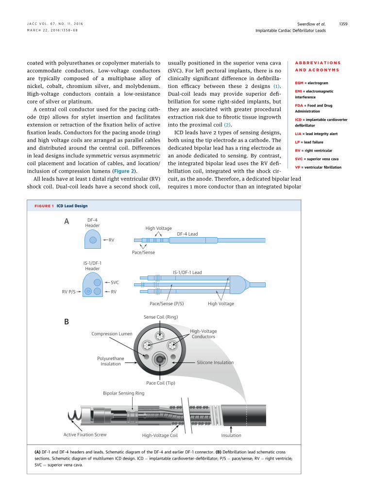
Although there are differences in details, mostmanufacturers use similar materials. All current ICDleads and most in service today are of the multilumendesign (Figure 1). Cabled conductors are coated withPTFE (poly-tetrafluoroethylene) and ETFE (ethylene-tetrafluoroethylene) and placed in an insulating sili-cone cylinder with 3 to 6 lumens, which may be
ivision of Cardiology, Virgina Commonwealth Uni-
eived honoraria for lectures fromMedtronic, St. Jude
llectual property with Medtronic. Dr. Ellenbogen has
nd St. JudeMedical; served on data safetymonitoring
nsulting fees from Medtronic, Boston Scientific, and
J A C C V O L . 6 7 , N O . 1 1 , 2 0 1 6 Swerdlow et al.M A R C H 2 2 , 2 0 1 6 : 1 3 5 8 – 6 8 Implantable Cardiac Defibrillator Leads
1359
coated with polyurethanes or copolymer materials toaccommodate conductors. Low-voltage conductorsare typically composed of a multiphase alloy ofnickel, cobalt, chromium silver, and molybdenum.High-voltage conductors contain a low-resistancecore of silver or platinum.
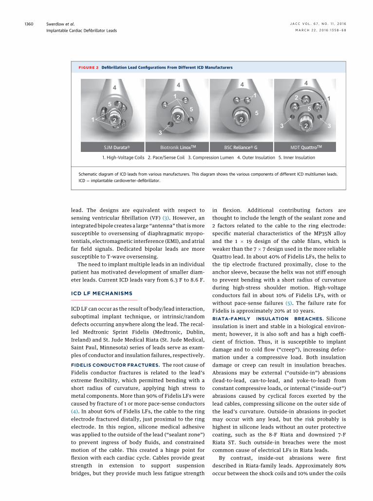
A central coil conductor used for the pacing cath-ode (tip) allows for stylet insertion and facilitatesextension or retraction of the fixation helix of activefixation leads. Conductors for the pacing anode (ring)and high voltage coils are arranged as parallel cablesand distributed around the central coil. Differencesin lead designs include symmetric versus asymmetriccoil placement and location of cables, and location/inclusion of compression lumens (Figure 2).
All leads have at least 1 distal right ventricular (RV)shock coil. Dual-coil leads have a second shock coil,
FIGURE 1 ICD Lead Design
DF-4Header
RV
High Volta
Pace/Sense
IS-1/DF-1Header
RV P/S
SVC
RV
Pace/Sen
Sense Coil (
Compression Lumen
PolyurethaneInsulation
Pace Coil (
Bipolar Sensing Ring
Active Fixation Screw High-Voltag
A
B
(A) DF-1 and DF-4 headers and leads. Schematic diagram of the DF-4 a
sections. Schematic diagram of multilumen ICD design. ICD ¼ implantab
SVC ¼ superior vena cava.
usually positioned in the superior vena cava(SVC). For left pectoral implants, there is noclinically significant difference in defibrilla-tion efficacy between these 2 designs (1).Dual-coil leads may provide superior defi-brillation for some right-sided implants, butthey are associated with greater proceduralextraction risk due to fibrotic tissue ingrowthinto the proximal coil (2).
ICD leads have 2 types of sensing designs,both using the tip electrode as a cathode. Thededicated bipolar lead has a ring electrode asan anode dedicated to sensing. By contrast,the integrated bipolar lead uses the RV defi-brillation coil, integrated with the shock cir-
cuit, as the anode. Therefore, a dedicated bipolar leadrequires 1 more conductor than an integrated bipolar
geDF-4 Lead
IS-1/DF-1 Lead
se (P/S) High Voltage
Ring)
High-VoltageConductors
Silicone Insulation
Tip)
e Coil Insulation
nd earlier DF-1 connector. (B) Defibrillation lead schematic cross
le cardioverter-defibrillator; P/S ¼ pace/sense; RV ¼ right ventricle;
FIGURE 2 Defibrillation Lead Configurations From Different ICD Manufacturers
SJM Durata® Biotronik LinoxTM BSC Reliance® G MDT QuattroTM
Schematic diagram of ICD leads from various manufacturers. This diagram shows the various components of different ICD multilumen leads.
ICD ¼ implantable cardioverter-defibrillator.
Swerdlow et al. J A C C V O L . 6 7 , N O . 1 1 , 2 0 1 6
Implantable Cardiac Defibrillator Leads M A R C H 2 2 , 2 0 1 6 : 1 3 5 8 – 6 8
1360
lead. The designs are equivalent with respect tosensing ventricular fibrillation (VF) (3). However, anintegrated bipole creates a large “antenna” that ismoresusceptible to oversensing of diaphragmatic myopo-tentials, electromagnetic interference (EMI), and atrialfar field signals. Dedicated bipolar leads are moresusceptible to T-wave oversensing.
The need to implant multiple leads in an individualpatient has motivated development of smaller diam-eter leads. Current ICD leads vary from 6.3 F to 8.6 F.
ICD LF MECHANISMS
ICD LF can occur as the result of body/lead interaction,suboptimal implant technique, or intrinsic/randomdefects occurring anywhere along the lead. The recal-led Medtronic Sprint Fidelis (Medtronic, Dublin,Ireland) and St. Jude Medical Riata (St. Jude Medical,Saint Paul, Minnesota) series of leads serve as exam-ples of conductor and insulation failures, respectively.
FIDELIS CONDUCTOR FRACTURES. The root cause ofFidelis conductor fractures is related to the lead’sextreme flexibility, which permitted bending with ashort radius of curvature, applying high stress tometal components. More than 90% of Fidelis LFs werecaused by fracture of 1 or more pace-sense conductors(4). In about 60% of Fidelis LFs, the cable to the ringelectrode fractured distally, just proximal to the ringelectrode. In this region, silicone medical adhesivewas applied to the outside of the lead (“sealant zone”)to prevent ingress of body fluids, and constrainedmotion of the cable. This created a hinge point forflexion with each cardiac cycle. Cables provide greatstrength in extension to support suspensionbridges, but they provide much less fatigue strength
in flexion. Additional contributing factors arethought to include the length of the sealant zone and2 factors related to the cable to the ring electrode:specific material characteristics of the MP35N alloyand the 1 � 19 design of the cable filars, which isweaker than the 7 � 7 design used in the more reliableQuattro lead. In about 40% of Fidelis LFs, the helix tothe tip electrode fractured proximally, close to theanchor sleeve, because the helix was not stiff enoughto prevent bending with a short radius of curvatureduring high-stress shoulder motion. High-voltageconductors fail in about 10% of Fidelis LFs, with orwithout pace-sense failures (5). The failure rate forFidelis is approximately 20% at 10 years.RIATA-FAMILY INSULATION BREACHES. Siliconeinsulation is inert and stable in a biological environ-ment; however, it is also soft and has a high coeffi-cient of friction. Thus, it is susceptible to implantdamage and to cold flow (“creep”), increasing defor-mation under a compressive load. Both insulationdamage or creep can result in insulation breaches.Abrasions may be external (“outside-in”) abrasions(lead-to-lead, can-to-lead, and yoke-to-lead) fromconstant compressive loads, or internal (“inside-out”)abrasions caused by cyclical forces exerted by thelead cables, compressing silicone on the outer side ofthe lead’s curvature. Outside-in abrasions in-pocketmay occur with any lead, but the risk probably ishighest in silicone leads without an outer protectivecoating, such as the 8-F Riata and downsized 7-FRiata ST. Such outside-in breaches were the mostcommon cause of electrical LFs in Riata leads.
By contrast, inside-out abrasions were firstdescribed in Riata-family leads. Approximately 80%occur between the shock coils and 10% under the coils
J A C C V O L . 6 7 , N O . 1 1 , 2 0 1 6 Swerdlow et al.M A R C H 2 2 , 2 0 1 6 : 1 3 5 8 – 6 8 Implantable Cardiac Defibrillator Leads
1361
(6). Presently, there is no consensus about the rootcause of Riata’s susceptibility to this type of abrasion.However, recent reports of inside-out abrasionsoccurring in the Biotronik Linox S or SD lead indicatethat the root cause is not limited to Riata-family leads(7). There are important design differences betweenthe 2 leads, but both have a “symmetric” design, withthe helical coil to the tip electrode in the center, asopposed to an “asymmetric” design, in which thepacing coil is offset. However, it is not certain whetherthis design similarity relates to the root cause.
In Riata-family leads without external copolymertubing (Model 1500 and 7000 series), inside-outabrasions present most commonly as exteriorizedcables that can be identified radiographically betweenthe proximal and distal shock coils (8–11). At diag-nosis, most leads with externalized cables havenormal electrical function due to intact ETFE innerinsulation. A meta-analysis of leads assessed byroutine, passive monitoring reported externalizedcables in 23.1% of leads, but electrical failure in only6.3% (6). Riata ST Optim and Durata leads have anouter, abrasion-resistant copolymer tubing, originallyintended to prevent outside-in abrasions. If inside-out abrasion occurs through the silicone, this tubingcontains the cables and prevents exteriorization,providing it remains intact. It is not known whetherthis tubing exerts forces on the silicone that reducethe underlying process of inside-out abrasion of thesilicone lead body. A multicenter study reported noexternalized cables in 3-year routine follow-up, butsuch cases have been reported (11,12). Furthermore,most Optim-coated leads lack Optim between thesilicone and shock coil. Thus, inside-out abrasionsunder the shock coil may result in contact of a con-ducting cable with a shock coil (13–15). Contact be-tween the proximal coil and cable to the distal coilmay short the high-voltage conductors, preventingshock delivery to the patient.
INCIDENCE OF LF
The incidence of LF is difficult to determine due toreporting bias. Monitoring of lead performance reliesprimarily on industry-based, post-market surveillanceand voluntary reporting to the Food and Drug Admin-istration (FDA).Most failed leads are not explanted andreturned for analysis or reported to the FDA. Further-more, systematic LF may not be recognized untilenough leads have been in service for a sufficientperiod of time. For instance, a multicenter study, withshort follow-up of 18 � 16.7 months, reported a 0.21%incidence of insulation damage for Riata leads (non-Optim) (10), greatly underestimating the failure rate
with longer follow-up. The MAUDE (Manufacturer andUser Data Experience) database receives physician re-ports related to medical devices. In addition tounderreporting and reporting bias, the utility of thisdatabase is limited by nonvalidated entries.
When recalled models are excluded from analysis,the incidence of LF for currently implanted leadsranges from 0.28% to 1.14%, showing that most leadsdemonstrate a high level of reliability (16). Lead sur-vival rates for recalled versus nonrecalled leadsseparate at about 2 years after implantation.
DIAGNOSIS OF LF
CLINICAL PRESENTATIONS. LF may present withelectricalmalfunction of pace-sense components,withelectrical malfunction of high-voltage components, ormechanical complications. Pace-sense malfunctionsare diagnosed most frequently. Oversensing withnormal pacing impedance is the initial electricalabnormality with either conductor fracture or insu-lation breach in $60% to 85% of LFs (4,17,18). Oneanalysis of 84 LFs from multiple manufacturers, theinitial presentation was oversensing with normalimpedance in 70%, oversensing with abrupt change inimpedance in 19%, and impedance changes withoutoversensing in 11%. Because LF-related oversensingis often rapid, it presents most commonly with in-appropriate detection of VF in older ICDs. Today, itcommonly presents with alerts for suspected over-sensing (see the following section). It also presents asinhibition of bradycardia or resynchronization pacing(18). Pace-sense malfunctions may also present withloss of capture, undersensing, or abrupt decrease inR-wave amplitude.
Shock componentmalfunctions aremost commonlyidentified on the basis of changes in shock impedanceand, less commonly, as failed defibrillation shocks.Rarely, shorted high-voltage outputs due to insulationbreaches may cause ICD generator failure. The inci-dence of shock electrogram (EGM) abnormalities isunknown because this is not monitored consistently.
Rarely, LF may present with mechanical compli-cations. Exteriorized cables from inside-out insu-lation breaches may damage the tricuspid valve andserve as a nidus for formation of thrombus and veg-etations in endocarditis.
OVERSENSING IN THE DIAGNOSIS OF
PACE–SENSE COMPONENT MALFUNCTION
Oversensing refers to sensing of signals other thanthe QRS complex (19,20). Oversensing that varies witheach cardiac cycle (cyclical oversensing) indicates anintracardiac source. Characteristics of the oversensed
TABLE 1 EGM Charac
Early or late post-impl
LF—pace-sense comp
Conductor fracture
Connection proble
Insulation breach—
Insulation breach—
LF—high-voltage com
High-voltage coil f
High-voltage coil i
Conditions that maywith LF
EMI
Diaphragmatic my
P-wave or T-wavedouble coun
VF
Calcification at eleinterface
Lead–lead interact
Intraoperative and peri
Air trapped in hea
Lead dislodgment
EGM ¼ electrogram; EMI ¼
Swerdlow et al. J A C C V O L . 6 7 , N O . 1 1 , 2 0 1 6
Implantable Cardiac Defibrillator Leads M A R C H 2 2 , 2 0 1 6 : 1 3 5 8 – 6 8
1362
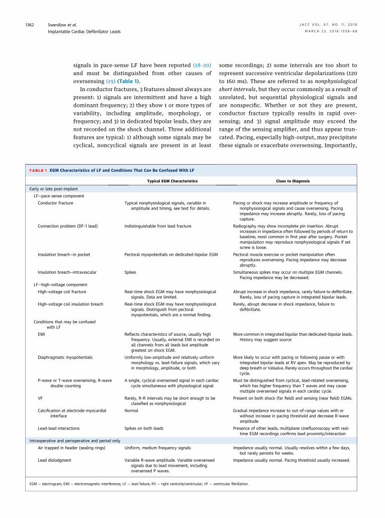
signals in pace-sense LF have been reported (18–20)and must be distinguished from other causes ofoversensing (19) (Table 1).
In conductor fractures, 3 features almost always arepresent: 1) signals are intermittent and have a highdominant frequency; 2) they show 1 or more types ofvariability, including amplitude, morphology, orfrequency; and 3) in dedicated bipolar leads, they arenot recorded on the shock channel. Three additionalfeatures are typical: 1) although some signals may becyclical, noncyclical signals are present in at least
teristics of LF and Conditions That Can Be Confused With LF
Typical EGM Characteristics
ant
onent
Typical nonphysiological signals, variable inamplitude and timing; see text for details.
m (DF-1 lead) Indistinguishable from lead fracture
in pocket Pectoral myopotentials on dedicated-bipolar EGM
intravascular Spikes
ponent
racture Real-time shock EGM may have nonphysiologicalsignals. Data are limited.
nsulation breach Real-time shock EGM may have nonphysiologicalsignals. Distinguish from pectoralmyopotentials, which are a normal finding.
be confused
Reflects characteristics of source, usually highfrequency. Usually, external EMI is recorded oall channels from all leads but amplitudegreatest on shock EGM.
opotentials Uniformly low-amplitude and relatively uniformmorphology vs. lead-failure signals, which varin morphology, amplitude, or both
oversensing; R-waveting
A single, cyclical oversensed signal in each cardiaccycle simultaneous with physiological signal
Rarely, R-R intervals may be short enough to beclassified as nonphysiological
ctrode–myocardial Normal
ions Spikes on both leads
operative and period only
der (sealing rings) Uniform, medium frequency signals
Variable R-wave amplitude. Variable oversensedsignals due to lead movement, includingoversensed P waves.
electromagnetic interference; LF ¼ lead failure; RV ¼ right ventricle/ventricular; VF ¼ ven
some recordings; 2) some intervals are too short torepresent successive ventricular depolarizations (120to 160 ms). These are referred to as nonphysiologicalshort intervals, but they occur commonly as a result ofunrelated, but sequential physiological signals andare nonspecific. Whether or not they are present,conductor fracture typically results in rapid over-sensing; and 3) signal amplitude may exceed therange of the sensing amplifier, and thus appear trun-cated. Pacing, especially high-output, may precipitatethese signals or exacerbate oversensing. Importantly,
Clues to Diagnosis
Pacing or shock may increase amplitude or frequency ofnonphysiological signals and cause oversensing. Pacingimpedance may increase abruptly. Rarely, loss of pacingcapture.
Radiography may show incomplete pin insertion. Abruptincreases in impedance often followed by periods of return tobaseline; most common in first year after surgery. Pocketmanipulation may reproduce nonphysiological signals if setscrew is loose.
Pectoral muscle exercise or pocket manipulation oftenreproduces oversensing. Pacing impedance may decreaseabruptly.
Simultaneous spikes may occur on multiple EGM channels.Pacing impedance may be decreased.
Abrupt increase in shock impedance, rarely failure to defibrillate.Rarely, loss of pacing capture in integrated bipolar leads.
Rarely, abrupt decrease in shock impedance, failure todefibrillate.
nMore common in integrated bipolar than dedicated-bipolar leads.
History may suggest source
yMore likely to occur with pacing or following pause or with
integrated bipolar leads at RV apex. May be reproduced bydeep breath or Valsalva. Rarely occurs throughout the cardiaccycle.
Must be distinguished from cyclical, lead-related oversensing,which has higher frequency than T waves and may causemultiple oversensed signals in each cardiac cycle.
Present on both shock (far field) and sensing (near field) EGMs.
Gradual impedance increase to out-of-range values with orwithout increase in pacing threshold and decrease R-waveamplitude
Presence of other leads; multiplane cinefluoroscopy with real-time EGM recordings confirms lead proximity/interaction
Impedance usually normal. Usually resolves within a few days,but rarely persists for weeks.
Impedance usually normal. Pacing threshold usually increased.
tricular fibrillation.
CENTRAL ILLUSTRATION ICD Leads: Approach to the Patient With Suspected LF
Heart Lead(s)
Patient with suspected lead failure
Does electrogram show oversensing?
Lead failure or header connection issue
ICD system-related oversensing?
Abrupt change in pace-sense or shock impedence?
Perform additional evaluations*
EVALUATING SUSPECTED ICD LEAD FAILURE
Implantablecardiacdefibrillator(ICD)
Not lead failure
Swerdlow, C.D. et al. J Am Coll Cardiol. 2016; 67(11):1358–68.
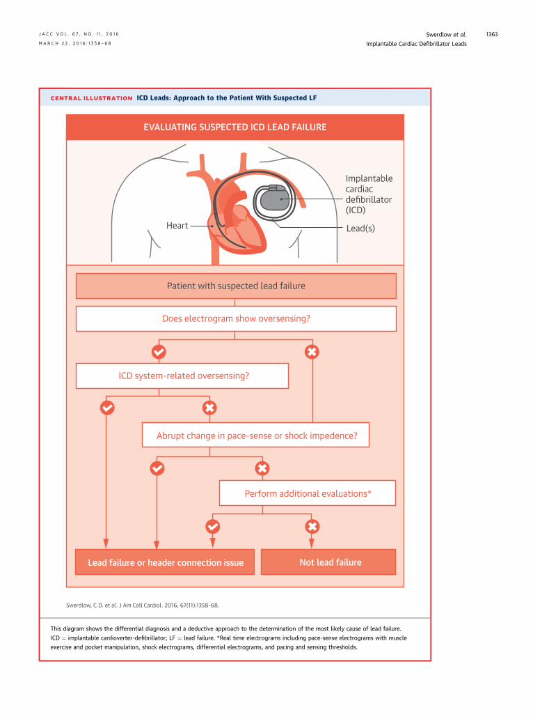
This diagram shows the differential diagnosis and a deductive approach to the determination of the most likely cause of lead failure.
ICD ¼ implantable cardioverter-defibrillator; LF ¼ lead failure. *Real time electrograms including pace-sense electrograms with muscle
exercise and pocket manipulation, shock electrograms, differential electrograms, and pacing and sensing thresholds.
J A C C V O L . 6 7 , N O . 1 1 , 2 0 1 6 Swerdlow et al.M A R C H 2 2 , 2 0 1 6 : 1 3 5 8 – 6 8 Implantable Cardiac Defibrillator Leads
1363
Swerdlow et al. J A C C V O L . 6 7 , N O . 1 1 , 2 0 1 6
Implantable Cardiac Defibrillator Leads M A R C H 2 2 , 2 0 1 6 : 1 3 5 8 – 6 8
1364
connection problems between DF-1 leads and headersresult in identical EGM patterns.
Unlike conductor fractures, insulation breaches donot themselves generate abnormal signals. Instead,oversensed signals pass through the insulation breachto enter the intact conductor. Thus, EGM patternsvary, reflecting the source signal. Nonphysiologicalsignals may be recorded from multiple conductors(e.g., inside-out abrasion) or multiple leads (lead–leadabrasion). Pectoral myopotentials recorded fromshock EGMs that include the pectoral ICD can be anormal finding, but pectoral myopotentials recordedon the RV sensing channel usually indicate an in-pocket insulation breach. EGMs of inside-outbreaches of Riata leads often have characteristicspikes on the sensing channel or on both sensing andshock channels, which may represent mechanical in-teractions (18). Like oversensing caused by conductorfractures, oversensing related to insulation breachesusually is intermittent and transient.
IMPEDANCE AND IMPEDANCE TRENDS
IN THE DIAGNOSIS OF LF
ICDs measure electrical resistance (impedance) peri-odically for both pace-sense and high-voltage con-ductors (17,19). An abrupt 50% to 75% relativeincrease in pace-sense impedance is a highly specificindicator of an ICD system problem, either conductorfracture or a connection problem. Conversely, agradual impedance increase without oversensingusually occurs at the electrode–myocardial interface,and lead replacement is not indicated unless pacingor sensing is compromised. An abrupt decrease inimpedance of a chronically implanted lead usuallyindicates an insulation breach, but overall impedancechanges are rare in pace-sense insulation breaches.
Fractures of high-voltage conductors often presentas abrupt increases in shock impedance, typically>75% (5). High shock impedancemay also bemeasuredif connections are faulty. Low shock impedance hasbeen reported in shock component insulationbreaches, but insulation may fail during high-voltageshocks, even if low-voltage impedance measure-ments are within the expected range. The CentralIllustration summarizes the approach to the patientwith suspected LF.
REMOTE MONITORING AND LF DIAGNOSTICS
Remote monitoring is the accepted standard forfollow-up of ICD patients and plays a central role inthe management of patients with at-risk leads. Bothpatient-initiated and fully automated systemsimprove recognition of lead malfunction (21).
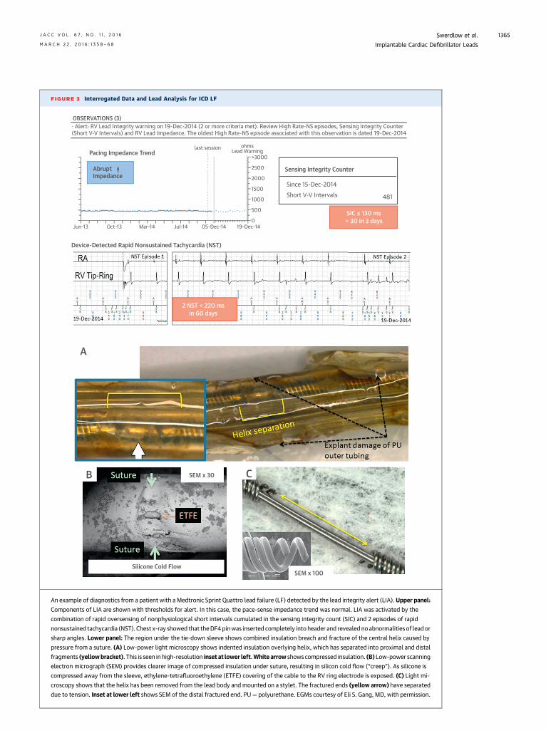
Two types of LF diagnostics are of greatest valuewhen used with remote monitoring. The Medtroniclead integrity alert (LIA) algorithm and Boston Sci-entific latitude lead alert are designed to improveearly detection of conductor fractures and to de-crease inappropriate shocks by monitoring fornonphysiological short intervals, rapid oversensing,and abrupt changes in relative impedance (17).Once triggered, both initiate remote-monitoringnotification in devices with wireless telemetry.Additionally, LIA initiates an audible patient alert andextends the detection duration for VF to reduceinappropriate shocks. Both types of alerts need to bereviewed for well-documented false positives unre-lated to LF (18). Figure 3 shows an example of a LFdiagnosed by LIA. Note that minor oversensingoccurred, and impedance was normal, despiteextensive insulation and conductor damage.
The Medtronic lead noise algorithm and St. JudeMedical SecureSense RV lead noise discriminationalgorithm are designed to differentiate oversensingdue to LF from ventricular tachycardia/VF and with-hold therapies in the presence of oversensing. Thesealgorithms compare signals on the sensing and shockchannels. Sensing-channel signals that do not corre-spond to shock-channel signals indicate oversensing.Both are ineffective for oversensing related to the RVcoil in integrated bipolar leads. The lead noise algo-rithm has been validated clinically. It has not beenreported to withhold shocks for clinical VF; non–lead-related oversensing that would have resulted ininappropriate shocks triggers most of the false posi-tives. SecureSense has not been validated clinically;false-positive triggers have occurred during normalrhythm (22).
There are fewer ICD diagnostics for shock conduc-tors than for pace-sense conductors. However, anautomatic shocking vector switching algorithm (Dy-namic Tx, St. Jude Medical) can prevent pulse gener-ator damage and ensure shock delivery in at least somehigh-voltage insulation breaches that cause shortingin the shock output circuit of dual-coil leads. If a shortis present in 1 of the 2 dual-coil shock pathways (RV coilto can, RV coil to SVC coil) during a shock, it aborts theshocks and then delivers the next shock through theintact pathway (23).
MANAGEMENT OF PATIENTS WITH
FUNCTIONING RECALLED LEADS
For a patient with a functioning recalled lead, man-agement focuses around a comprehensive baselineassessment and prescribing an intensified monitoringplan. A baseline chest radiograph may identify
FIGURE 3 Interrogated Data and Lead Analysis for ICD LF
· Alert: RV Lead Integrity warning on 19-Dec-2014 (2 or more criteria met). Review High Rate-NS episodes, Sensing Integrity Counter(Short V-V Intervals) and RV Lead Impedance. The oldest High Rate-NS episode associated with this observation is dated 19-Dec-2014
An example of diagnostics from a patient with a Medtronic Sprint Quattro lead failure (LF) detected by the lead integrity alert (LIA). Upper panel:
Components of LIA are shown with thresholds for alert. In this case, the pace-sense impedance trend was normal. LIA was activated by the
combination of rapid oversensing of nonphysiological short intervals cumulated in the sensing integrity count (SIC) and 2 episodes of rapid
nonsustained tachycardia (NST). Chest x-ray showed that theDF4pinwas inserted completely into header and revealed noabnormalities of leador
sharp angles. Lower panel: The region under the tie-down sleeve shows combined insulation breach and fracture of the central helix caused by
pressure from a suture. (A) Low-power light microscopy shows indented insulation overlying helix, which has separated into proximal and distal
fragments (yellowbracket). This is seen in high-resolution inset at lower left.White arrow shows compressed insulation. (B) Low-power scanning
electron micrograph (SEM) provides clearer image of compressed insulation under suture, resulting in silicon cold flow (“creep”). As silicone is
compressed away from the sleeve, ethylene-tetrafluoroethylene (ETFE) covering of the cable to the RV ring electrode is exposed. (C) Light mi-
croscopy shows that the helix has been removed from the lead body and mounted on a stylet. The fractured ends (yellow arrow) have separated
due to tension. Inset at lower left shows SEM of the distal fractured end. PU¼ polyurethane. EGMs courtesy of Eli S. Gang, MD, with permission.
J A C C V O L . 6 7 , N O . 1 1 , 2 0 1 6 Swerdlow et al.M A R C H 2 2 , 2 0 1 6 : 1 3 5 8 – 6 8 Implantable Cardiac Defibrillator Leads
1365
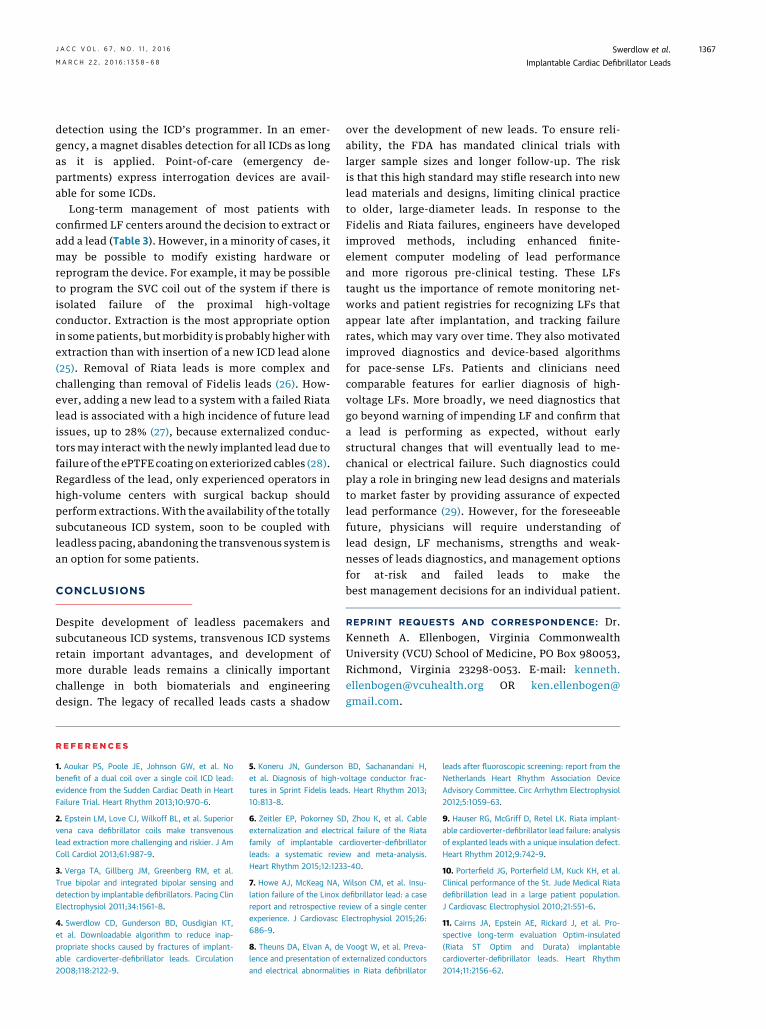
TABLE 3 Decision-Making For Lead Management
Factors to consider
Mechanism of LF
Clinical presentation of LF: frequent shocks, defibrillation failure,among others
Incidence of LF: time course
Age of patient
Age of lead
Indications for the ICD (primary vs. secondary prevention)
Underlying rhythm
True bipolar vs. integrated bipolar design
DF-4 vs. DF-1 design
Number of chronic or associated leads
Advisory recommendations
Prior cardiac surgery
Comorbidities and prognosis
Prior generator change
Other clinical predictors of LF: risk factors predicting higher rate ofLF
Pacemaker dependence
Risk of lead extraction: dual coil vs. single coil; length of implant;prior cardiac surgery; institution experience; operatorexperience; other risk factors
Management options
Observe with reprogramming
Modify existing hardware configuration
Insert new rate/sense lead
Insert new ICD lead
Insert defibrillation coil
Extract and reimplant a new transvenous system
Implant subcutaneous ICD system
Implant hybrid system
Abbreviations as in Tables 1 and 2.
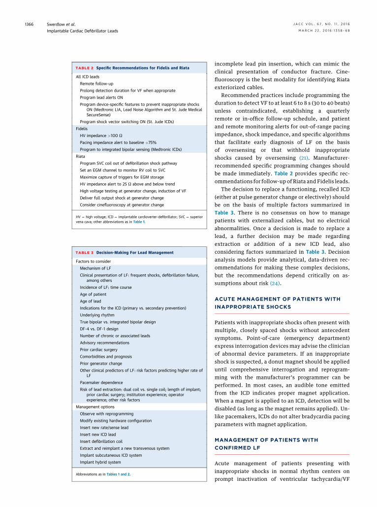
TABLE 2 Specific Recommendations for Fidelis and Riata
All ICD leads
Remote follow-up
Prolong detection duration for VF when appropriate
Program lead alerts ON
Program device-specific features to prevent inappropriate shocksON (Medtronic LIA, Lead Noise Algorithm and St. Jude MedicalSecureSense)
Program shock vector switching ON (St. Jude ICDs)
Fidelis
HV impedance >100 U
Pacing impedance alert to baseline þ75%
Program to integrated bipolar sensing (Medtronic ICDs)
Riata
Program SVC coil out of defibrillation shock pathway
Set an EGM channel to monitor RV coil to SVC
Maximize capture of triggers for EGM storage
HV impedance alert to 25 U above and below trend
High voltage testing at generator change; induction of VF
Deliver full output shock at generator change
Consider cinefluoroscopy at generator change
HV ¼ high voltage; ICD ¼ implantable cardioverter-defibrillator; SVC ¼ superiorvena cava; other abbreviations as in Table 1.
Swerdlow et al. J A C C V O L . 6 7 , N O . 1 1 , 2 0 1 6
Implantable Cardiac Defibrillator Leads M A R C H 2 2 , 2 0 1 6 : 1 3 5 8 – 6 8
1366
incomplete lead pin insertion, which can mimic theclinical presentation of conductor fracture. Cine-fluoroscopy is the best modality for identifying Riataexteriorized cables.
Recommended practices include programming theduration to detect VF to at least 6 to 8 s (30 to 40 beats)unless contraindicated, establishing a quarterlyremote or in-office follow-up schedule, and patientand remote monitoring alerts for out-of-range pacingimpedance, shock impedance, and specific algorithmsthat facilitate early diagnosis of LF on the basisof oversensing or that withhold inappropriateshocks caused by oversensing (21). Manufacturer-recommended specific programming changes shouldbe made immediately. Table 2 provides specific rec-ommendations for follow-up of Riata and Fidelis leads.
The decision to replace a functioning, recalled ICD(either at pulse generator change or electively) shouldbe on the basis of multiple factors summarized inTable 3. There is no consensus on how to managepatients with externalized cables, but no electricalabnormalities. Once a decision is made to replace alead, a further decision may be made regardingextraction or addition of a new ICD lead, alsoconsidering factors summarized in Table 3. Decisionanalysis models provide analytical, data-driven rec-ommendations for making these complex decisions,but the recommendations depend critically on as-sumptions about risk (24).
ACUTE MANAGEMENT OF PATIENTS WITH
INAPPROPRIATE SHOCKS
Patients with inappropriate shocks often present withmultiple, closely spaced shocks without antecedentsymptoms. Point-of-care (emergency department)express interrogation devices may advise the clinicianof abnormal device parameters. If an inappropriateshock is suspected, a donut magnet should be applieduntil comprehensive interrogation and reprogram-ming with the manufacturer’s programmer can beperformed. In most cases, an audible tone emittedfrom the ICD indicates proper magnet application.When a magnet is applied to an ICD, detection will bedisabled (as long as the magnet remains applied). Un-like pacemakers, ICDs do not alter bradycardia pacingparameters with magnet application.
MANAGEMENT OF PATIENTS WITH
CONFIRMED LF
Acute management of patients presenting withinappropriate shocks in normal rhythm centers onprompt inactivation of ventricular tachycardia/VF
J A C C V O L . 6 7 , N O . 1 1 , 2 0 1 6 Swerdlow et al.M A R C H 2 2 , 2 0 1 6 : 1 3 5 8 – 6 8 Implantable Cardiac Defibrillator Leads
1367
detection using the ICD’s programmer. In an emer-gency, a magnet disables detection for all ICDs as longas it is applied. Point-of-care (emergency de-partments) express interrogation devices are avail-able for some ICDs.
Long-term management of most patients withconfirmed LF centers around the decision to extract oradd a lead (Table 3). However, in a minority of cases, itmay be possible to modify existing hardware orreprogram the device. For example, it may be possibleto program the SVC coil out of the system if there isisolated failure of the proximal high-voltageconductor. Extraction is the most appropriate optionin some patients, butmorbidity is probably higher withextraction than with insertion of a new ICD lead alone(25). Removal of Riata leads is more complex andchallenging than removal of Fidelis leads (26). How-ever, adding a new lead to a system with a failed Riatalead is associated with a high incidence of future leadissues, up to 28% (27), because externalized conduc-tors may interact with the newly implanted lead due tofailure of the ePTFE coating on exteriorized cables (28).Regardless of the lead, only experienced operators inhigh-volume centers with surgical backup shouldperform extractions.With the availability of the totallysubcutaneous ICD system, soon to be coupled withleadless pacing, abandoning the transvenous system isan option for some patients.
CONCLUSIONS
Despite development of leadless pacemakers andsubcutaneous ICD systems, transvenous ICD systemsretain important advantages, and development ofmore durable leads remains a clinically importantchallenge in both biomaterials and engineeringdesign. The legacy of recalled leads casts a shadow
over the development of new leads. To ensure reli-ability, the FDA has mandated clinical trials withlarger sample sizes and longer follow-up. The riskis that this high standard may stifle research into newlead materials and designs, limiting clinical practiceto older, large-diameter leads. In response to theFidelis and Riata failures, engineers have developedimproved methods, including enhanced finite-element computer modeling of lead performanceand more rigorous pre-clinical testing. These LFstaught us the importance of remote monitoring net-works and patient registries for recognizing LFs thatappear late after implantation, and tracking failurerates, which may vary over time. They also motivatedimproved diagnostics and device-based algorithmsfor pace-sense LFs. Patients and clinicians needcomparable features for earlier diagnosis of high-voltage LFs. More broadly, we need diagnostics thatgo beyond warning of impending LF and confirm thata lead is performing as expected, without earlystructural changes that will eventually lead to me-chanical or electrical failure. Such diagnostics couldplay a role in bringing new lead designs and materialsto market faster by providing assurance of expectedlead performance (29). However, for the foreseeablefuture, physicians will require understanding oflead design, LF mechanisms, strengths and weak-nesses of leads diagnostics, and management optionsfor at-risk and failed leads to make thebest management decisions for an individual patient.
REPRINT REQUESTS AND CORRESPONDENCE: Dr.Kenneth A. Ellenbogen, Virginia CommonwealthUniversity (VCU) School of Medicine, PO Box 980053,Richmond, Virginia 23298-0053. E-mail: [email protected] OR [email protected].
RE F E RENCE S
1. Aoukar PS, Poole JE, Johnson GW, et al. Nobenefit of a dual coil over a single coil ICD lead:evidence from the Sudden Cardiac Death in HeartFailure Trial. Heart Rhythm 2013;10:970–6.
2. Epstein LM, Love CJ, Wilkoff BL, et al. Superiorvena cava defibrillator coils make transvenouslead extraction more challenging and riskier. J AmColl Cardiol 2013;61:987–9.
3. Verga TA, Gillberg JM, Greenberg RM, et al.True bipolar and integrated bipolar sensing anddetection by implantable defibrillators. Pacing ClinElectrophysiol 2011;34:1561–8.
4. Swerdlow CD, Gunderson BD, Ousdigian KT,et al. Downloadable algorithm to reduce inap-propriate shocks caused by fractures of implant-able cardioverter-defibrillator leads. Circulation2008;118:2122–9.
5. Koneru JN, Gunderson BD, Sachanandani H,et al. Diagnosis of high-voltage conductor frac-tures in Sprint Fidelis leads. Heart Rhythm 2013;10:813–8.
6. Zeitler EP, Pokorney SD, Zhou K, et al. Cableexternalization and electrical failure of the Riatafamily of implantable cardioverter-defibrillatorleads: a systematic review and meta-analysis.Heart Rhythm 2015;12:1233–40.
7. Howe AJ, McKeag NA, Wilson CM, et al. Insu-lation failure of the Linox defibrillator lead: a casereport and retrospective review of a single centerexperience. J Cardiovasc Electrophysiol 2015;26:686–9.
8. Theuns DA, Elvan A, de Voogt W, et al. Preva-lence and presentation of externalized conductorsand electrical abnormalities in Riata defibrillator
leads after fluoroscopic screening: report from theNetherlands Heart Rhythm Association DeviceAdvisory Committee. Circ Arrhythm Electrophysiol2012;5:1059–63.
9. Hauser RG, McGriff D, Retel LK. Riata implant-able cardioverter-defibrillator lead failure: analysisof explanted leads with a unique insulation defect.Heart Rhythm 2012;9:742–9.
10. Porterfield JG, Porterfield LM, Kuck KH, et al.Clinical performance of the St. Jude Medical Riatadefibrillation lead in a large patient population.J Cardiovasc Electrophysiol 2010;21:551–6.
11. Cairns JA, Epstein AE, Rickard J, et al. Pro-spective long-term evaluation Optim-insulated(Riata ST Optim and Durata) implantablecardioverter-defibrillator leads. Heart Rhythm2014;11:2156–62.
Swerdlow et al. J A C C V O L . 6 7 , N O . 1 1 , 2 0 1 6
Implantable Cardiac Defibrillator Leads M A R C H 2 2 , 2 0 1 6 : 1 3 5 8 – 6 8
1368
12. Deeprasertkul P, Yunus A, Thakur R. Conductorexternalization in a Riata ST Optim lead. Europace2013;15:1012.
13. Hauser RG, Abdelhadi RH, McGriff DM, et al.Failure of a novel silicone-polyurethane copol-ymer (Optim) to prevent implantable cardioverter-defibrillator lead insulation abrasions. Europace2013;15:278–83.
14. Swerdlow CD, Kass RM, Khoynezhad A, et al.Inside-out insulation failure of a defibrillator leadwith abrasion-resistant coating. Heart Rhythm2013;10:1063–6.
15. Shah AD, Hirsh DS, Langberg JJ. User-reportedabrasion-related lead failure is more common withDurata compared to other implantable cardiacdefibrillator leads.HeartRhythm2015;12:2376–80.
16. Liu J, Brumberg G, Rattan R, et al. Longitudinalfollow-up of implantable cardioverter leads. Am JCardiol 2014;113:103–6.
17. Swerdlow CD, Gunderson BD, Ousdigian KT,et al. Downloadable software algorithm reducesinappropriate shocks caused by implantablecardioverter-defibrillator lead fractures: a pro-spective study. Circulation 2010;122:1449–55.
18. Ellenbogen KA, Gunderson BD, Stromberg KD,et al. Performance of a Lead Integrity Alert toassist in the clinical diagnosis of implantable car-dioverter defibrillator lead failures: analysis ofdifferent implantable cardioverter defibrillator
20. Gunderson BD, Swerdlow CD, Wilcox JM, et al.Causes of ventricular oversensing in implantablecardioverter-defibrillators: implications for diag-nosis of lead fracture. Heart Rhythm 2010;7:626–33.
21. Slotwiner D, Varma N, Akar JG, et al. HRSexpert consensus statement on remote interro-gation and monitoring for cardiovascularimplantable electronic devices. Heart Rhythm2015;12:e69–100.
22. Koneru JN, Kaszala K, Bordachar P, et al.Spectrum of issues detected by an ICD diagnosticalert that utilizes far-field electrograms: clinicalimplications. Heart Rhythm 2015;12:957–67.
23. Mixobuchi M, Enjoji Y. Successful detection ofa high-energy electrical short circuit and a“rescue” shock using a novel automatic shocking-vector adjustment algorithm. Heart Rhythm CaseRep 2015;1:27–30.
24. Mendenhall GS, Saba S. Prophylactic leadextraction at implantable cardioverter-defibrillator generator change. Circ ArrhythmElectrophysiol 2014;7:330–6.
25. Mulpuru SK, Pretorius VG, Birgersdotter-Green UM. Device infections: management andindications for lead extractions. Circulation 2013;128:1031–8.
26. Bongiomi MG, Di Cori A, Segreti L, et al.Transvenous extraction profile of Riata leads:procedural outcomes and technical complexity ofmechanical removal. Heart Rhythm 2015;12:580–7.
27. Parvathaneni SV, Ellis CR, Rottman JN.High prevalence of insulation failure with exter-nalized cables in St. Jude Medical Riata familyICD leads; fluoroscopic grading scale and correla-tion to extracted leads. Heart Rhythm 2012;9:1218–24.
28. Ricci RP, Pignalberi C, Magris B, et al. Can wepredict and prevent adverse events related tohigh-voltage implantable cardioverter defibrillatorlead failure? J Interv Card Electrophysiol 2012;33:113–21.
29. Kollmann DT, Swerdlow CD, Kroll MW, et al.ICD lead failure detection through high frequencyimpedance. Conf Proc IEEE Eng Med Biol Soc2014;2014:6487–92.
KEY WORDS fracture, implantabledefibrillator leads, insulation, recall,ventricular fibrillation