2
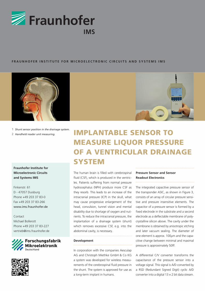
The human brain is filled with cerebrospinal fluid (CSF), which is produced in the ventric- les. Patients suffering from normal pressure hydrocephalus (NPH) produce more CSF as they resorb. This leads to an increase of the intracranial pressure (ICP) in the skull, what may cause progressive enlargement of the head, convulsion, tunnel vision and mental disability due to shortage of oxygen and nut- rients. To reduce the intracranial pressure, the implantation of a drainage system (shunt) which removes excessive CSF, e.g. into the abdominal cavity, is necessary. Development In corporation with the companies Aesculap AG and Christoph Miethke GmbH & Co KG a system was developed for wireless measu- rements of the cerebrospinal fluid pressure in the shunt. The system is approved for use as a long-term implant in humans. IMPLANTABLE SENSOR TO MEASURE LIQUOR PRESSURE OF A VENTRICULAR DRAINAGE SYSTEM Pressure Sensor and Sensor Readout Electronics The integrated capacitive pressure sensor of the transponder ASIC, as shown in Figure 3, consists of an array of circular pressure sensi- tive and pressure insensitive elements. The capacitor of a pressure sensor is formed by a fixed electrode in the substrate and a second electrode as a deflectable membrane of poly- crystalline silicon above. The cavity under the membrane is obtained by anisotropic etching and later vacuum sealing. The diameter of one element is approx. 100µm and the capa- citive change between minimal and maximal pressure is approximately 50fF. A differential C/V converter transforms the capacitance of the pressure sensor into a voltage signal. This signal is A/D converted by a RSD (Redundant Signed Digit) cyclic A/D converter into a digital 13 × 2 bit data stream. 1 Shunt sensor position in the drainage system. 2 Handheld reader unit measuring. FRAUNHOFER INSTITUTE FOR MICROELECTRONIC CIRCUITS AND SYSTEMS IMS Fraunhofer Institute for Microelectronic Circuits and Systems IMS Finkenstr. 61 D - 47057 Duisburg Phone +49 203 37 83-0 Fax +49 203 37 83-266 www.ims.fraunhofer.de Contact Michael Bollerott Phone +49 203 37 83-227 [email protected]