Page 1
IMPLEMENTATION AND EVALUATION OF A TDMA
BASED PROTOCOL FOR WIRELESS SENSOR
NETWORKS
ROBERT FISKE
Bachelor of Computer Engineering
Bachelor of Science in Computer Information Systems
December 2007
Cleveland State University
submitted in partial fulfillment of the requirements for the degree
MASTERS OF SCIENCE IN SOFTWARE ENGINEERING
at the
CLEVELAND STATE UNIVERSITY
December 2010
Page 2
This thesis has been approved for the
Department of ELECTRICAL AND COMPUTER ENGINEERING
and the College of Graduate Studies by
Thesis Committee Chairperson, Dr. Chansu Yu
Department/Date
Dr. Nigamanth Sridhar
Department/Date
Dr. Wenbing Zhao
Department/Date
Page 3
Dedicated to my family and friends
Page 4
ACKNOWLEDGMENTS
I would like to thank Dr. Yu for his support since undergrad, and for providing
countless interesting projects to work on over the years. I would also like to thank
Adrienne and Jan in the department office for their various assistance over the years.
Both Dr. Sridhar and Dr. Zhao for serving on my defense committee.
The Pohang Institute of Science and Technology in Pohang, for allowing me
to conduct research using their facilities. From POSTECH Nguyen B. Truong for his
assistance in debugging portions of my code. Ah-Young Heo, Heejoo Choi, Seok Seong
Jeon and Sangwook Bak for their assistance in finding my way around POSTECH.
All the members of the Mobile Computing Lab at CSU in my time there, Sai
Krishna Gumudavally, Sachin Hirve, Xiang Li, Murali Krishna Marunganti, Kushal
Shah, Tianning Shen
iv
Page 5
IMPLEMENTATION AND EVALUATION OF A TDMA
BASED PROTOCOL FOR WIRELESS SENSOR
NETWORKS
ROBERT FISKE
ABSTRACT
When evaluating MAC layer network protocols for wireless sensor networks,
performing simulations of a protocol’s operation can provide great insight into the
performance of the protocol. In order to prove that a protocol will work in a real
setting and not just at the theoretical level, however, there is no substitute for evalua-
tion with a physical implementation. This thesis discusses a physical implementation
and evaluation of the Many-to-One-Sensor-to-Sink (MOSS) MAC layer protocol for
sink based wireless sensor networks using the MAC Layer Architecture for TinyOS.
MOSS is a Time Division Multiple Access (TDMA) based protocol first proposed in
an earlier work. MOSS aims to utilize the strengths and alleviate the weaknesses
of TDMA. In addition to discussing and evaluating the physical MOSS implemen-
tation, the process of developing MAC layer protocol implementations with MLA is
also discussed.
v
Page 6
TABLE OF CONTENTS
Page
ACKNOWLEDGMENTS . . . . . . . . . . . . . . . . . . . . . . . . . . . . . iv
ABSTRACT . . . . . . . . . . . . . . . . . . . . . . . . . . . . . . . . . . . . v
LIST OF FIGURES . . . . . . . . . . . . . . . . . . . . . . . . . . . . . . . . ix
CHAPTER
I. INTRODUCTION . . . . . . . . . . . . . . . . . . . . . . . . . . . . . . . 1
II. RELATED WORKS . . . . . . . . . . . . . . . . . . . . . . . . . . . . . 4
2.1 Wireless Sensor Networks . . . . . . . . . . . . . . . . . . . . . . 4
2.2 TinyOS . . . . . . . . . . . . . . . . . . . . . . . . . . . . . . . . 5
2.3 Mote . . . . . . . . . . . . . . . . . . . . . . . . . . . . . . . . . 5
2.4 Previous WSN MAC Protocols . . . . . . . . . . . . . . . . . . . 7
2.4.1 S-MAC . . . . . . . . . . . . . . . . . . . . . . . . . . . . 7
2.4.2 B-MAC . . . . . . . . . . . . . . . . . . . . . . . . . . . . 7
2.4.3 X-MAC . . . . . . . . . . . . . . . . . . . . . . . . . . . . 8
2.4.4 TDMA . . . . . . . . . . . . . . . . . . . . . . . . . . . . 9
2.4.5 SS-TDMA . . . . . . . . . . . . . . . . . . . . . . . . . . 10
III. MOSS Protocol . . . . . . . . . . . . . . . . . . . . . . . . . . . . . . . 11
3.1 Scheduling Phase . . . . . . . . . . . . . . . . . . . . . . . . . . . 12
3.2 Data Phase . . . . . . . . . . . . . . . . . . . . . . . . . . . . . . 13
IV. DESIGN AND IMPLEMENTATION . . . . . . . . . . . . . . . . . . . 14
4.1 MLA . . . . . . . . . . . . . . . . . . . . . . . . . . . . . . . . . 14
4.1.1 MLA Introduction . . . . . . . . . . . . . . . . . . . . . . 14
4.1.2 Why MLA . . . . . . . . . . . . . . . . . . . . . . . . . . 15
vi
Page 7
4.2 Initialization . . . . . . . . . . . . . . . . . . . . . . . . . . . . . 16
4.3 Scheduling Phase . . . . . . . . . . . . . . . . . . . . . . . . . . . 17
4.3.1 Send PADV . . . . . . . . . . . . . . . . . . . . . . . . . 17
4.3.2 Receive PADV . . . . . . . . . . . . . . . . . . . . . . . . 17
4.3.3 Send PSEL . . . . . . . . . . . . . . . . . . . . . . . . . . 19
4.3.4 Receive PSEL . . . . . . . . . . . . . . . . . . . . . . . . 20
4.3.5 Sending the Schedule . . . . . . . . . . . . . . . . . . . . 20
4.3.6 Receiving the Schedule . . . . . . . . . . . . . . . . . . . 20
4.4 Data Phase . . . . . . . . . . . . . . . . . . . . . . . . . . . . . . 21
4.4.1 Handling Data . . . . . . . . . . . . . . . . . . . . . . . . 22
4.5 Handling Trouble . . . . . . . . . . . . . . . . . . . . . . . . . . 23
4.5.1 Missing PADV . . . . . . . . . . . . . . . . . . . . . . . . 23
4.5.2 Missing PSEL . . . . . . . . . . . . . . . . . . . . . . . . 24
4.5.3 PSEL Collision . . . . . . . . . . . . . . . . . . . . . . . . 24
4.5.4 Sending Permission Denied by Schedule . . . . . . . . . . 24
4.5.5 Missed Schedule . . . . . . . . . . . . . . . . . . . . . . . 25
4.5.6 Missing Data and Missing Beacon . . . . . . . . . . . . . 25
4.5.7 Synchronization . . . . . . . . . . . . . . . . . . . . . . . 26
V. PERFORMANCE EVALUATION . . . . . . . . . . . . . . . . . . . . . 27
5.1 Data Phase . . . . . . . . . . . . . . . . . . . . . . . . . . . . . . 27
5.1.1 Experimental Overview . . . . . . . . . . . . . . . . . . . 27
5.1.2 Testing Scenario . . . . . . . . . . . . . . . . . . . . . . . 28
5.1.3 PDR . . . . . . . . . . . . . . . . . . . . . . . . . . . . . 29
5.1.4 Latency . . . . . . . . . . . . . . . . . . . . . . . . . . . . 30
5.2 Scheduling Phase . . . . . . . . . . . . . . . . . . . . . . . . . . . 32
5.2.1 Experimental Overview . . . . . . . . . . . . . . . . . . . 32
vii
Page 8
5.2.2 Testing Scenario . . . . . . . . . . . . . . . . . . . . . . . 33
5.2.3 Results . . . . . . . . . . . . . . . . . . . . . . . . . . . . 34
VI. CONCLUSION AND FUTURE WORK . . . . . . . . . . . . . . . . . . 36
6.1 Conclusion . . . . . . . . . . . . . . . . . . . . . . . . . . . . . . 36
6.2 MLA Evaluation . . . . . . . . . . . . . . . . . . . . . . . . . . . 37
6.3 Future Work . . . . . . . . . . . . . . . . . . . . . . . . . . . . . 38
BIBLIOGRAPHY . . . . . . . . . . . . . . . . . . . . . . . . . . . . . . . . . 40
APPENDICES . . . . . . . . . . . . . . . . . . . . . . . . . . . . . . . . . . . 43
A. Slot Event Handler . . . . . . . . . . . . . . . . . . . . . . . . . . . . . . 44
B. BigSlot End . . . . . . . . . . . . . . . . . . . . . . . . . . . . . . . . . . 51
C. Send Broadcast Message . . . . . . . . . . . . . . . . . . . . . . . . . . . 56
D. Receive Message . . . . . . . . . . . . . . . . . . . . . . . . . . . . . . . 58
E. Lower Level Code . . . . . . . . . . . . . . . . . . . . . . . . . . . . . . . 65
F. Data Handling Functions . . . . . . . . . . . . . . . . . . . . . . . . . . . 68
viii
Page 9
LIST OF FIGURES
Figure Page
1 Tmote Sky iv Mote Device http://www.sic.rma.ac.be/Projects/
WSN/tmote_sky.jpg . . . . . . . . . . . . . . . . . . . . . . . . . . . 6
2 Timing of scheduling phase operation. . . . . . . . . . . . . . . . . . 16
3 MOSS parent selection scenario. . . . . . . . . . . . . . . . . . . . . . 19
4 Data Phase Operation for The Nodes in the Given Tree. . . . . . . . 21
5 Timing of scheduling and data phase operations. . . . . . . . . . . . . 22
6 The measured PDR of data phase transmission. . . . . . . . . . . . . 29
7 The measured packet latency of data phase transmissions. . . . . . . 31
8 Experimental setup for scheduling phase experiments. . . . . . . . . . 33
9 The measured success rate of parent acquisition. . . . . . . . . . . . . 34
ix
Page 10
CHAPTER I
INTRODUCTION
This thesis will evaluate the Many-to-One-Sensor-to-Sink (MOSS) protocol for
wireless sensor networks proposed in [1]. Both the theory behind the protocol as well
as a description of a physical implementation of the protocol will be presented here.
The MOSS protocol is a MAC layer network protocol designed for Wireless Sensor
Networks (WSN) with the goal of providing a robust, low energy method for data
propagation from a sensor to a sink node.
Wireless sensor networks are an ever-growing area of network technology, which
unlike regular networks are very dependent on their energy efficiency in addition to
the normal requirements for networks such as reliability. For old fashioned PC based
wireless networks technologies such as Carrier Sense Multiple Access (CSMA) provide
reliable network performance, but these protocols are expensive when it comes to en-
ergy consumption reducing their desirability in WSNs. The Time Division Multiple
Access (TDMA) protocol provides a much more energy reliable approach for WSNs
but this reliability comes at the cost of flexibility.
In high traffic situations CSMA can lead to highly congested networks due to
1
Page 11
collisions [8, 9, 10, 11]. CSMA also loses efficiency since any time spent using CSMA
is time that the radio is on but is not relaying any useful information. TDMA presents
a different approach for WSNs which alleviates these shortcomings of CSMA based
protocols [ 8, 12, 13, 14, 15, 16, 17]. In TDMA each node is assigned a given time
slot where it has exclusive rights to the medium; by having exclusive rights to the
medium, nodes do not need to use technology such as CSMA and may instead freely
transmit without fear of collision at their assigned time [18]. This also allows for con-
sistent energy consumption regardless of the amount of traffic in the network since
nodes know when they must transmit and do not need to spend time confirming this
fact. In spite of these performance improvements over CSMA, TDMA is not widely
used because of several factors including the high cost of generating a usable schedule
for a given network and its inflexibility to change [1].
MOSS is presented here as an improvement to the TDMA concept which main-
tains the energy efficiency and reliability of TDMA but makes it more flexible and
therefore more useful in real world environments. One key difference between MOSS
and other attempts to improve upon TDMA is that other protocols such as SS-
TDMA/Z-MAC [14] use a TDMA based schedule for data transmission, but still rely
on technologies such as CSMA for scheduling, MOSS uses a TDMA based schedule
for all operations within the protocol. SS-TDMA’s use of CSMA allows it great op-
portunity to provide improved performance in low traffic environments but comes
at a a high cost in the area of power consumption. By sticking to a predetermined
schedule for all data transmissions MOSS has a guaranteed duty cycle which allows
maximum power saving potential.
The rest of this thesis is organized as follows. Sections II gives an overview
of other MAC protocols for wireless sensor networks. Section III looks at the MOSS
protocol, while section IV examines the physical implementation of MOSS and the
2
Page 12
foundation it is built upon. The experimental results are examined in section V.
Section VI closes this thesis by evaluating the conclusions derived from this work and
presenting a direction of future study for this project.
3
Page 13
CHAPTER II
RELATED WORKS
2.1 Wireless Sensor Networks
Wireless Sensor Networks are an ever growing technology in both the Research
and Industrial communities. As technology advances the amount of processing power
available and size required for such power is increasing and shrinking respectively.
While a simple computer once took up an entire room equivalent processing power
can now be held in the palm of your hand. This allows for hundreds or thousands
of devices to be placed in an environment which can then be studied in much more
detail than was once possible, and all of this can be done relatively cheaply compared
to the past.
For such a setting processing power is not a major concern as currently available
technology provides phones with more processing power than the computers of a
decade ago. However, in such an environment the major limiting factor is power
consumption as a device should be left unattended for months or perhaps years on
end with only a simple battery to sustain it. To this end MAC protocols for WSNs
4
Page 14
often strive to maximize power efficiency.
2.2 TinyOS
The MOSS implementation is built on top of the TinyOS operating system
developed at the University of California at Berkley. TinyOS is a ubiquitous event
driven model for developing wireless sensor networks. To meet the requirements of a
wireless sensor network system TinyOS provides both a modular design as well as an
architecture that can deal with concurrency intensive applications[3]. Programming
in TinyOS is developed in the nesC [4] programming language. Nesc has syntax sim-
ilar to the C language and acts as an interface to the standard C language.
When TinyOS code is compiled the nesC code is translated into C instructions
which are then compiled by a cross compiling GCC (GNU Compiler Collection) [22].
TinyOS allows designers to access low level hardware functionality if required, but in
general gives higher level access to the user allowing for a more abstracted program-
ming model. The MLA framework described in more detail later provides for further
abstractions allowing code to be written which will work on any hardware device that
has implemented the framework allowing for portable code to be written for mote
devices.
2.3 Mote
The hardware used to implement the MOSS protocol was a combination of
TMote Sky iv and Crosswbow motes. Both of these devices are members of the
TelosB family of wireless sensors[20, 21]. The motes contain 10KB of RAM and 48KB
of program memory. The micro controller on the device is a TI MSP430 and consumes
3mW of power during the active state and 15uW when asleep, with a wakeup time of
5
Page 15
Figure 1: Tmote Sky iv Mote Device http://www.sic.rma.ac.be/Projects/WSN/
tmote_sky.jpg
6us. The radio on the devices is a CC2420 with a 250kbps data rate using O-QPSK
modulation. The antenna used on the mote is an integrated Inverted-F microstrip
design providing 50 meter indoor range and upwards of 125 meter outdoor range [20].
Communication with the PC for programming and outputting data is accomplished
through a USB port on the mote device.
The CC2420 radio can be configured for various power levels. A higher power
level reduces energy efficiency but extends transmission range. At its highest level the
radio has a 17.4mA current consumption and outputs at 0dB. At the lowest power
setting the current consumption is 8.5mA with a power output of -25dB [19].
The Telos architecture was developed at The University of California at Berkley.
The CC2420 radio provides transmission in the 2.4GHz range and generates RSSI (Re-
ceived Signal Strength Indicator) [20] values which are used in the MOSS protocol to
choose from potential parents.
6
Page 16
2.4 Previous WSN MAC Protocols
2.4.1 S-MAC
Striving to save power in wireless sensor networks is not a new concept and
many protocols have been proposed which aim to reduce power consumption and
increase the lifetime of a wireless sensor node. Among these protocols is the Sensor-
MAC (S-MAC) protocol proposed by Ye et. al. in [2]. In S-MAC when in an idle
state motes will use a predefined duty cycle and sense the medium during their active
state. Nodes attempt to schedule their sleep period with their neighbors so that they
are awake at the same time, however, the protocol does not guarantee that nodes
will use matching schedules. Nodes then transmit their schedule to their neighbors
so that a node who wishes to transmit to a given node knows when that node will be
awake.
If a node finds that one of its neighbor’s schedule is different than it’s own it
alters its schedule so that it is awake for both time periods. While S-MAC nodes
reduce their needed duty cycle by knowing a specific range of time that transmissions
may be sent or received it still relies on carrier sensing to avoid collisions during
its contention period. In high traffic situations when many nodes attempt to send
to a given node the overhead of sensing the medium further reduces the limited
transmission time during the nodes active period.
2.4.2 B-MAC
The default MAC protocol in TinyOS is B-MAC [6]. B-MAC achieves a reduc-
tion in power by allowing the radio to sleep for long periods of time while ensuring
that all nodes wakeup once within a specified period of time. Transmitting nodes
then send a preamble that is slightly longer than this period of time, this ensures
7
Page 17
that the receiving node will wakeup during the transmission period and sense the
medium, discovering that someone wishes to transmit to it.
In order to attempt to reduce collisions CSMA is used to deter two nodes from
both attempting to transmit data at the same time. The protocol allows for substan-
tial power savings for the receiving node as it can go to sleep for long periods of time
without fearing the loss of a packet. However this presents two major drawbacks.
From a performance standpoint this is an inefficient approach as during the trans-
mission of the long preamble no data is being sent. From a power saving standpoint
although it saves energy for receivers by allowing lower duty cycles it consumes more
power for transmitters as a node must transmit data for the duration of the preamble
which may actually be much longer than the transmission time for the actual data
which the node wishes to send.
B-MAC also reduces power efficiency by requiring a node that overhears the
long preamble to remain in the on state until the preamble is finished and the data
packet which indicates the intended receiver is sent meaning a node that hears the
preamble may stay awake for a large portion of that preamble only to learn that
there is no information intended for it and no reason for it to have been awake for
all that time. In addition to this this the use of CSMA presents further delays and
inefficiencies as the back off time and CSMA transmission attempt both represent
time spent in an on state while not transmitting any useful information [1].
2.4.3 X-MAC
The X-MAC protocol introduced by [5] represents an improvement on B-MAC
by inserting the intended receiver’s identity in the preamble and then allowing nodes
who hear the preamble to see if they are the intended receiver and if they are not,
then they are permitted to return to a low power state. The node that is the intended
8
Page 18
receiver then transmits an acknowledgment to the transmitting node allowing that
node to then stop sending its preamble and instead start the transmission of the
actual data. While this presents a major improvement over the original B-MAC
design it still can force a node to transmit for extended periods of time without
actually transmitting anything of use if the intended receiver doesn’t wake up until
near the end of the preamble. In addition its use of CSMA may force a node who has
something to send to idle in an active power state while it waits for its turn to send
data.
2.4.4 TDMA
A key advantage of the TDMA protocol is the fact that its transmissions op-
erate in a completely predictable way, sticking to its established schedule. While
this does present limited flexibility in a wireless sensor network predictability can
be a major asset. In an environment where a device needs to operate on a single
battery over the course of several years using a protocol with a predictable nature
allows engineers to plan the project with more confidence that the devices will be
able to fulfill their requirements. While the transmission portion of TDMA allows for
superior power consumption it fails to take advantage of this on the receiving end as
it must use methods such as low power listening for the reception of messages since
it does not know when it will receive a message. MOSS addresses this concern by
retaining knowledge of when it could possibly receive a message allowing the radio to
be shut down completely when it will be certain it will not receive a message. This
will be discussed in further detail later in this thesis.
9
Page 19
2.4.5 SS-TDMA
The MLA paper [7] presents a hybrid protocol similar to Z-MAC [14] called
SS-TDMA. This protocol works to improve TDMA performance by allowing a node to
attempt to send in a slot it doesn’t own if it has a message to send and the owner of the
slot is idle. This is detected by having the slot owner begin transmitting immediately
in its own slot if it has something to send, other nodes wait for a small period of time
in order to check if owner has begun transmission. This protocol improves on the
throughput of TDMA by allowing nodes to transmit early rather than waiting for its
assigned time, however this comes at the cost of energy efficiency since nodes must
remain awake to both check if it is able to steal a slot as well as parent nodes must
remain awake at all times to see if one of its children is attempting to send.
10
Page 20
CHAPTER III
MOSS Protocol
The MOSS protocol is a TDMA based protocol with data transmission occur-
ring in much the same manner as TDMA. MOSS splits time into several units, the
smallest of which is a slot which is equivalent to a slot in TDMA. A grouping of slots
are called a bigslot, the number of slots in a bigslot varies by implementation. A
frame is a group of three bigslots.
In TDMA collisions are avoided by dividing time into uniform slot times and
having nodes only transmit in a slot that it owns. Since nodes only transmit in prede-
termined intervals there is no need for collision detection and avoidance mechanisms
such as CSMA. One of the key disadvantages of TDMA is the limited flexibility of
a predetermined schedule as well as the inability to take advantage of opportuni-
ties to turn the radio off since a parent has no knowledge of when it may receive a
message. MOSS addresses both of these concerns by periodically generating a new
schedule as well as retaining child transmission schedules in order to take advantage
of unscheduled time and turn off the radio, reducing radio duty cycle and saving
energy.
11
Page 21
3.1 Scheduling Phase
While the data phase of MOSS is very similar to TDMA, MOSS uses a novel
approach to generating its schedule. When a node first joins the network it listens
for a parent advertisement packet (PADV), once it receives this packet it begins full
participation in the network. Upon receiving a PADV packet a node checks the (RSSI)
value of the received packet as well as the ID of the sender, and the number of hops
between the sender and the sink. If the packet is the first PADV received by the node
or if the hop count is less than its current parent the node marks the sender as its
new parent. If the hop count is equal to its current parent the node then compares
the RSSI of packet to the RSSI of the PADV it received from its current parent, if the
new packet is stronger the node marks the sender as its new parent. When a node
selects a new parent it randomly selects a slot which it wishes to transmit in, while its
bigslot is determined by its hop count from the sink. If a node is not in the scheduling
phase it will set itself to the scheduling phase upon receiving a PADV from its parent
or from a node that it will consider its parent from that point on. The PADV is
considered to be received in the first bigslot of a frame. In the second bigslot of the
frame a node sends a PSEL packet to its chosen parent, the slot is chosen randomly
for a new parent and if the parent remains the same as it was at the end of the last
data phase the same slot is chosen. In the third bigslot of the frame a node receives a
schedule from its chosen parent, it then checks the index of the schedule with a value
equal to the slot it chose, if it finds its node ID in this location then it considers itself
to have permission to send.
Regardless of the result of the schedule check a node will take the same actions
in the rest of the scheduling phase, it will not however attempt to send during the
data phase. At the beginning of the next frame (first bigslot) during the node’s slot
it transmits its own PADV message. In the following bigslot the node receives PSEL
12
Page 22
messages from its potential children. When it receives one of these PSEL messages the
node marks the sender’s ID in an array it stores as its schedule. In the third bigslot of
the frame it then transmits a schedule packet with the contents of its schedule array.
The node then sleeps for one full frame so that it won’t interfere with its children’s
scheduling process. After this rest period the data phase begins for the given node.
3.2 Data Phase
When the data phase begins a node is permitted to transmit data in its bigslot
during its slot, if it has no data to send it may also transmit synchronization beacons
during this time. During the data phase a node will sleep for slots in which it has no
scheduled activity, the node wakes up in order to transmit data, as well as during it’s
children’s transmission slots so that it may hear data from them. During its parent’s
bigslot a node may sleep for the entire bigslot. A node begins the wakeup process
during the slot before its slot or its children’s slot and sleeps when it has finished
sending or upon receiving a packet from its child. At the end of the data phase a
node again goes to sleep for one frame in order to not interfere with its parent’s
scheduling phase.
13
Page 23
CHAPTER IV
DESIGN AND IMPLEMENTATION
4.1 MLA
4.1.1 MLA Introduction
The Mac Layer Architecture (MLA) was developed by Kevin Klues, et al as
a common building block for developing and comparing MAC layer implementations
for TinyOS [7]. Their work abstracts many of the lower level details of developing a
MAC protocol allowing developers to concentrate on the high level operations of their
chosen protocol. By using the MLA platform developers do not have to worry about
scrutiny into whether they gave their protocol an unfair advantage in the low level
operations of the mote, such as using unique radio functionality for their protocol, but
not for others. This allows for a fair comparison of the protocols. The MLA format
also helps speed up development as once the MLA architecture has been ported to
use a given mote architecture then all developers may implement their protocol on
that architecture without needing to learn the inner workings of the new mote.
14
Page 24
4.1.2 Why MLA
The MLA platform was chosen for development because it provided a frame-
work for the necessary underlying features of the MOSS protocol. It also provides
several sample implementations that both assisted in developing MOSS and provide a
proven, reliable, and fair implementation of other protocols to compare with MOSS.
Although the scheduling for MOSS is heavily customized one of the key features MLA
provides are controls for node timing, including the ability to use a slot based sched-
ule. By using MLA the implementation has better protection against future changes
to TinyOS than if the code was written directly to a certain version of TinyOS. As
long as the MLA format is maintained MAC layer code has a stable set of interfaces
to build to, and any changes in the underlying functionality of TinyOS is abstracted
from the protocol implementation code.
In the remainder of this section the MOSS implementation will be described.
Deviations from the proposed protocol including optimizations, as well as workarounds
that are required due to the MLA framework. The MOSS protocol was implemented
by modifying the pure-tdma implementation provided in the TinyOS contrib folder.
This code was originally written by the research group of Chenyang Lu for their
MLA paper [7]. This particular implementation was chosen because MOSS is an
enhancement of the TDMA protocol and as such by choosing to modify a TDMA
implementation a lot of the groundwork was already laid. Within the pure-tdma
implementation two files required heavy modification in order to implement MOSS.
Of these files, the one that required the most modification was PureTdmaSched-
ulerP.nc in the lib/macs/pure-tdma folder while the file BeaconSlotP.nc in the system
folder also required significant changes. PureTdmaSchedulerP.nc contained the basic
scheduling controls for the TDMA protocol. As released a node simply transmits in
the slot associated with its ID (node one in slot one, node two in slot two and so on).
15
Page 25
Figure 2: Timing of scheduling phase operation.
4.2 Initialization
The most basic unit of operation in MOSS is the slot, upon starting a mote
must set the parameters of operation for its slot and bigslot. The length of any
given slot is determined by setting the slotSize variable to the desired length (in mil-
liseconds), this value is then passed to the FrameConfiguration interface by calling
FrameConfiguration.setSlotLength. The bigslot size is set by setting the bi vari-
able, the value given is the number of slots per bigslot. This information is then
passed along to FrameConfiguration.setFrameLength. The majority of code written
for MOSS is held within the slot event of the Slotter interface, an interface which is
provided by MLA. This event is signaled at the beginning of each slot.
Upon powering up the sink node transmits a PADV beacon message as a
broadcast message in order to initiate construction of the tree. Since all transmissions
are to a single sink node and this node is likely to have a reliable source of energy the
sink node does not need to consider the case where the network is already active when
it powers on and can begin operation immediately. When non-sink nodes power up
they remain in the active state listening for a PADV signal from a potential parent
16
Page 26
before beginning operation according to the MOSS protocol. The generation and
processing of the PADV packet is described below.
4.3 Scheduling Phase
4.3.1 Send PADV
In the slot event when the scheduling phase is active and both the frame count
and bigslot are set to one a PADV packet is generated and sent when the node’s
transmission slot starts. The PADV packet contains the hop count of the node as
well as synchronization information. This information consists of the current slot, and
current bigslot, as well as a time stamp. The time stamp is added in the BeaconSlotP
file while everything else is set within slot.
4.3.2 Receive PADV
When a node receives a PADV message it checks the RSSI value of the incom-
ing packet. The node then checks the hop count of the incoming PADV, as well as
the source address. If the incoming packet has a lower hop count than its previous
parent and the source address is not considered to be an excluded address (based on
poor performance with this parent in the past) its parent is updated to the new src,
as well as a new random slot is chosen by calling the function updateParent which is
passed a pointer to the payload, the source address and the RSSI value. The RSSI
and src values are then stored for future reference while the payload is used to set
the proper bigslot for future transmissions by using the hop count information. The
hop count is stored along with the slot that the parent transmitted in, this is used so
that a child may wake up for future parental transmissions. The src address and hop
count are also checked against the previous value, if the new parent is of the same
17
Page 27
generation as the former parent and the parent has switched then the former parent
is stored as a potential backup in case the new parent becomes inaccessible before
the next scheduling phase.
A signal is then sent to the lower layer indicating the new parent, this informa-
tion is used solely for determining weather or not an incoming packet should be used
for synchronization. The inclusion of backup parent information was used because
of issues with the MLA framework. Within the MLA TDMA implementation clock
drift was a considerable problem with nodes often quickly beginning to disagree over
the current slot causing collisions when two or more nodes would think it was their
turn to send. In order to alleviate this problem additional synchronization was used
(described later) and child nodes may also detect if they can no longer hear from
their parent, and switch to their step parent.
If the incoming PADV message is neither an excluded address nor the current
parent, is of the same generation as the former parent, and has a stronger RSSI than
the current parent then once again the parent information is updated via updatePar-
ent. The PADV indicates a new backup parent when the incoming packet is from
neither the current parent, and excluded address, nor the current backup parent, but
has stronger RSSI than the current backup parent and is of the same generation as
the current parent. This is set using the setBackup function, which simply stores the
information of the new backup. If the source is the current parent, and the parent
is not an excluded address the value of the currently selected transmission slot is
checked, if the most significant bit of the slot value is set to one, this indicates a
previously denied transmission attempt and a new slot is randomly selected.
18
Page 28
Figure 3: MOSS parent selection scenario.
4.3.3 Send PSEL
During the first frame of the second bigslot a node transmits its parent select
message. While this message is intended for a single recipient, the transmission is
sent as a broadcast. The message is broadcast to all receivers for two purposes, both
relating to the problems with MLA discussed in the previous section. The primary
reason reason for the PSEL packet being sent as a broadcast is so that any of the
nodes currently treating the subject node as a parent can use the broadcast message
in order to synchronize, the second being so that a backup parent can be alerted to
the potential future child. The transmission of this PSEL message is sent in a slot
determined by the selection of a random number whenever a node detects that its
parent has changed, while the bigslot is determined by its hop count from the sink.
In order to determine which parent a node is attempting to select the PSEL message
contains the intended parent ID.
19
Page 29
4.3.4 Receive PSEL
Upon reception of a PSEL packet the intended destination address is checked
against the current node’s ID, if the message was intended for the given node the
source address is stored in the local schedule. However if the PSEL message was
intended for another recipient but has its hop count set as one greater than the
current node, and if the current slot of the schedule is free then the current schedule
value is set to be the source with the most significant bit set to one. This indicates
that the slot is occupied by a node which may wish to transmit to the given node in
the future if the foreign node’s parent becomes inaccessible (a potential stepchild).
However, the node does not wish to transmit presently indicating it is safe for the
current node to normally sleep during this slot and would only need to be active to
check for parental switches.
4.3.5 Sending the Schedule
When the current bigslot is three and the current slot is a node’s transmission
slot it sends a broadcast message that contains the current slot, and time stamp value,
as well as its current transmission schedule. The schedule is created by receiving
PSEL messages and is stored within the payload of a singular schedule packet that is
reused for each scheduling phase. This payload also includes space for the value of the
current slot that a node is transmitting its schedule in which is used in conjunction
with the time stamp for synchronization.
4.3.6 Receiving the Schedule
Upon receiving a schedule message a node checks the source address of the
schedule. If the message originates from the node’s parent it sets a flag indicating
that it has received a schedule and checks the index of its chosen transmission slot, if
20
Page 30
Figure 4: Data Phase Operation for The Nodes in the Given Tree.
the value matches its own ID then the node is considered to have permission to send
in the slot. If the sender was the selected backup parent the value in the desired slot
is also checked, if permission is granted the backup parent is confirmed, however if it
is denied the backup parent value is invalidated.
4.4 Data Phase
Once the schedule has been set MOSS works much in the same manner as
vanilla TDMA. In order to ensure that its messages do not collide with its siblings’
messages a node transmits only during its designated time period. Although not called
21
Page 31
Figure 5: Timing of scheduling and data phase operations.
for in the original MOSS protocol one potential improvement that was implemented
is the possibility for a node to detect a broken link between itself and its parent.
In this case the orphaned node would attempt to resume transmissions with its step
parent. To improve end to end latency the Big Slots are structured such that when
a child transmits to its parent the parent node will transmit to its own parent in the
following Big Slot.
4.4.1 Handling Data
Upon receiving a packet the type is checked, if the packet is of type DATA the
source address is checked. If the packet originates from a node’s parent then a flag
is set indicating the reception of a beacon that was used to synchronize the node at
the lower level, a counter that keeps track of the number of missed beacons is also
22
Page 32
reset. The intended recipient value is then checked, if the message was intended for
the the given an ifdef statement separates the actions of the sink from all other motes.
The sink calls SinkHandleData while all other nodes call storeCombineData. Both
functions are passed the start of the data in the payload as well as the length of the
data portion. The implementation of these functions should vary by the application
of the sensor network. The purpose of the storeCombineData function is to locally
store the data in convenient format for combining other data packets for delivery up
the tree, such as keeping a total value of a numerator and denominator so that the
sink can calculate an average value. SinkHandleData is intended to be a place where
the user can specify how the sink should interact with data that it receives, such as
printing values to a connected PC, or passing the values to a PC for more complex
data analysis/calculations. For the sink the Application level is then signaled about
the reception of the packet. For the purposes of synchronization a node may transmit
a synchronizing beacon in place of a data packet if it has nothing to send, this is done
whenever a node has nothing to transmit due to synchronization problems in MLA,
for a more reliable operating environment idle synchronization can occur at longer
intervals, or may not be needed at all. If a node receives such a packet it notes the
fact that it received a beacon and resets the missed beacon counter.
4.5 Handling Trouble
4.5.1 Missing PADV
A missed PADV message simply results in a node losing out on a potential
parent. If no PADVs are received for a node it will continue to try use its previous
parent.
23
Page 33
4.5.2 Missing PSEL
If a PSEL message is lost the parent is unaffected aside from the loss of a
potential child. The sending node deals with this error when it fails to receive per-
mission to send from the schedule of the parent it selected. For the sending node
this error is indistinguishable from the case of being denied permission to send upon
receiving the schedule and is handled there.
4.5.3 PSEL Collision
If two nodes successfully transmit a PSEL in the same slot then the second
PSEL to be received will be recorded in the schedule. Child nodes will see the effects
of this error when they are possibly denied permission to send upon receiving the
schedule.
4.5.4 Sending Permission Denied by Schedule
If the node finds that the value stored in its intended transmission slot when
it receives its parent’s schedule is different than its ID the most significant bit of
its chosen transmission slot is set. This indicates that it was denied permission to
send data but can still transmit its PADV in this slot. A counter (denyCount) is
also incremented, if the new counter value is greater than a preset value (EXCLU-
SION THRESHOLD) the node marks its parent as an excluded parent and then
resets the RSSI value, hop count and parent ID to default values so that a new par-
ent may be chosen. This is done so that a parent which has a strong but intermittent
signal can be passed over in favor of a weaker but more reliable link. If the incoming
schedule is from a node that has been selected as a backup parent the index associ-
ated with the selected transmission slot is checked, if the node finds its ID it sets the
backup parent slot to be equal to that slot, if it does not find its ID it invalidates
24
Page 34
its backup parent ID and backup parent RSSI, there is no exclusion checking for a
backup parent.
If a scheduling phase passes without a node receiving a schedule transmission
slot value has the most significant bit set, the hop count, parent ID and parent RSSI
values are invalidated, and the denyCount value is also incremented and the exclusion
threshold is checked and if exceeded the parent is marked for exclusion.
4.5.5 Missed Schedule
If a node finishes the scheduling phase without receiving a schedule it invali-
dates its parent, hop count and parent RSSI. It also sets the most significant bit of its
transmission slot and increments the denyCount variable, if the exclusion threshold
is exceeded it also marks its former parent as an excluded address.
4.5.6 Missing Data and Missing Beacon
When a new frame begins within the data phase the beacon flag is checked and
if no beacon was received the missed beacon counter is incremented, if the number of
consecutive missed beacons exceeds a preset threshold (BEACON EXCLUSION THRESHOLD)
and a backup parent is available the the node will signal the lower layer that it is
switching parents, it also locally sets its backup parent as its active parent. Nodes
wakeup during the transmission slots of their potential stepchildren in a certain in-
terval determined by the defined value SWITCH CHECK RATE which indicates a
number of frames between wakeups. During this period if a child wishes to switch
parents it sends a PSWITCH packet to its new parent, this packet contains the node
ID of the new parent. After sending the PSWITCH packet a node then invalidates
its backup parent value. A node knows it wishes to switch parents when its backup
parent and active parent have the same value.
25
Page 35
When a node receives a PSWITCH packet it checks if the packet was intended
for itself. If it was the intended receiver it checks its schedule to see if the node has
permission to send, if the index of the schedule for the slot the packet was received
in contains the address of the sender (with the most significant bit set to one) then
the child is adopted, and the most significant bit is cleared in the schedule. If the
original parent hears the PSWITCH packet of its child then it clears the slot in its
schedule so it can go to sleep during that slot.
4.5.7 Synchronization
In addition to the standard operation exceptions given above, during the course
of the implementation extra handling of node synchronization was found to be neces-
sary due to problems with the MLA framework. In the physical MOSS implementa-
tion synchronization occurs for all transmissions when a node hears a message from
its parent. The MOSS protocol only calls for synchronization when receiving a PADV
packet from a node that is chosen as a parent. This synchronization is handled in
the BeaconSlotP file. In the receive function the node ID of the incoming packet is
checked against the currently known value, if it is a match, or if the current parent
is listed as 0xFF (indicating that no parent has been selected yet) the packet is con-
sidered to be a synchronizing packet. The packet is then checked for the time stamp
and slot number stored in the payload. When a packet is sent out from this interface
the time stamp information is added, however if the pointer to the packet passed to
the send command is null then no message is sent, instead the the parent ID is set to
be equal to the value stored in the length parameter of the call, this is a workaround
to allow the upper layer to signal to the lower layer who its parent should be without
changing the connections between layers for MLA.
26
Page 36
CHAPTER V
PERFORMANCE EVALUATION
Two sets of experiments were run in order to evaluate the MOSS protocol, one
set of experiments demonstrating the scheduling phase, and another comparing the
data phase performance of MOSS as well as other MAC layer protocols utilizing the
MLA framework. Since the MLA based implementations of the other protocols are
designed without a routing protocol, only single hop experimental data is shown. The
experimental setups as well as results are discussed below.
5.1 Data Phase
5.1.1 Experimental Overview
To test the performance of the MOSS data phase, experiments were run with
the MOSS implementation as well as implementations of B-MAC, and SS-TDMA that
were provided with the MLA framework code. The MLA implementation of B-MAC
is actually a hybrid B-MAC/X-MAC protocol. The MLA B-MAC implementation
includes the ability of nodes to go to sleep for traffic not destined for them by including
27
Page 37
destination address information in the preamble. The B-MAC implementation also
uses repeating copies of the data packet in place of true preamble transmission. The
B-MAC experiments were run twice, once with a CCA Check-length of 5ms and again
with a CCA Check-length of 2ms. The CCA Check-length is the amount of time a
node stays awake when performing Clear Channel Assessment for CSMA. The MLA
paper states that a 8ms check is required for maximum reception while their code
uses a 2ms check. With a shorter check-length a mote can find the medium to be
clear when in actually a node is transmitting causing a collision.
5.1.2 Testing Scenario
The testing scenario consisted of twelve TelosB motes. Each experiment in-
cluded a sink mote, an event mote, and between one and 10 transmission motes. The
event mote acted as a driver event rather than a transmission node that was part of
the network. The event mote transmitted packets periodically based off of a sequence
of pseudo-random numbers. Upon receiving an event packet the data motes would
wait for two seconds and then attempt to send a packet to the sink. This delay was
introduced due to the fact that in a real environment the event would be sensor based,
meaning the radio would likely be in an idle state whenever a packet was to be sent.
However, since the event node is a radio transmission the radio in the experiments,
because of this if motes transmitted directly after witnessing the event they would
already be in an active state. The two second delay is sufficient time for the radio
to return to the idle state. The sink node received all data packets and recorded
performance metrics. To ensure event packets weren’t missed by the transmitting
nodes every node was kept in the active state until the event packet was received, at
which point the radio would be turned on or off based on the protocol being used.
Each node was elevated about fifteen centimeters from a table surface in order
28
Page 38
Figure 6: The measured PDR of data phase transmission.
to reduce near field effects[6]. The sink node was placed in the center of the table
while data transmission motes formed a circle around the sink. Each data transmis-
sion consisted of a single packet with a sixty byte payload. Packet retransmission
was not used in any of the experiments, whenever a packet was missed by the sink it
was considered to be lost. Each experiment was run forty times, and the performance
measurements are given as the average result of all of the runs.
5.1.3 PDR
For each protocol the Packet Delivery Ratio (PDR) was recorded by measuring
the number of packets received for a given event compared to the number of trans-
mitter nodes. As can be seen from the graph the PDR of MOSS is nearly 100%
29
Page 39
with only a few lost packets that are likely caused by clock drift causing the sink
node to go to sleep when a data node is transmitting. SS-TDMA suffers under high
traffic due to the slot stealing mechanism, which allows a node to reduce its latency
but by introducing possible collisions reduces PDR. The B-MAC protocol has vastly
different performance based on the check-length, while a 5ms check greatly increases
reception rates, it is also less energy efficient. The B-MAC PDR is also harmed by
MLA’s implementation of packet reception in B-MAC packets. In the MLA B-MAC
implementation, packets are only passed up to the higher layer when the medium is
IDLE or when sending data itself, otherwise the received packet is held in a queue,
however the queue size is only one, meaning if two packets are received back to back,
the second packet is dropped.
5.1.4 Latency
Latency, measured as the time between the event and the last received packet
(subtracting the delay time) is given in the graph above. For low numbers of sending
nodes MOSS has higher latency than the other protocols because it must adhere to
its schedule and if an event comes immediately after its transmitting slot the sender
must wait for its turn to arrive again, while the other nodes can attempt to send when
it finds the medium idle. For higher numbers of nodes however, MOSS compares fa-
vorably to the other protocols because it is able to send without question in its own
slot, while B-MAC has to compete for the medium and back off whenever it loses to
a competing node. SS-TDMA shows low latency due to its ability to compete when
the medium is free but falls back to its guaranteed slot similar to MOSS. Although
SS-TDMA shows a lower latency than MOSS it also has a much higher rate of lost
packets as described in the previous section.
The results for B-MAC are of particular interest as they show some of the
30
Page 40
Figure 7: The measured packet latency of data phase transmissions.
31
Page 41
flaws of the MLA framework, with the B-MAC protocol the absolute minimum la-
tency achievable for a single node should be 100ms+packet transmission time (100ms
is the preamble length), for two nodes this time should be doubled. However, the
experimental results show much better than expected latency. The cause of this
is primarily from two factors, one factor is the above-mentioned CCA check-length
problem, a node will begin transmitting when the protocol calls for it to wait. The
other cause is that the MLA implementation uses copies of the data packet as the
preamble and does not differentiate between a true data packet and a preamble packet
in the code, meaning what should be considered as a preamble is actually treated as
a received packet in the code, causing much lower latency than what is expected.
Although inconsistencies with the MLA framework result in values that don’t
seem feasible, the effects of these flaws are split between both negative and positives
side effects. In addition to this the general trend of the results are in line with what is
expected. The result trends show that in low traffic situations the contention based
protocols show better performance than MOSS due to the generally free medium,
while under high loads the overhead of CSMA severely degrades performance of con-
tention based protocols while MOSS performs at a level consistent with its low traffic
performance.
5.2 Scheduling Phase
5.2.1 Experimental Overview
Due to time and resource constraints setting up a true tree network to measure
the performance of the protocol over time was not a practical approach, instead in
addition to the measured data phase measures the viability of the MOSS scheduling
mechanism was shown in a separate set of experiments. The experiments were setup to
32
Page 42
Figure 8: Experimental setup for scheduling phase experiments.
repeatedly run the scheduling phase of the MOSS algorithm and record the frequency
at which motes were successfully able to achieve transmission permission from a
possible parent.
5.2.2 Testing Scenario
To measure the performance of the scheduling phase six motes were arranged
in a circle around two potential parents. This is not an ideal testing scenario since
a true tree is not formed, however, setting up a realistic tree based network within
space and time constraints proved to be infeasible.
When the parents sent PADV packets to the children, the children attempted
to acquire a parent according to the MOSS Protocol. The parent nodes would then
33
Page 43
Figure 9: The measured success rate of parent acquisition.
record which children they had granted permission to transmit to. This information
was then transmitted to a PC via the USB port. The total successful parent ac-
quisitions were then recorded along with the total opportunities to acquire a parent.
Results were measured for networks with eight, ten, twelve, and sixteen available slots
for the 6 transmitting nodes. Each experiment was run for ten scheduling phases and
then repeated five times providing fifty scheduling phases per network setup.
5.2.3 Results
The above graph displays the mean, median, and mode of the the combined
experimental data. The experiments show that for a network starved for slots nodes
will struggle to find acceptable parents, but given enough room the likelihood of
finding a parent increases considerably. The drop-off from a ten node network to a
34
Page 44
twelve node network can likely be explained with the probability that the random
numbers used by some of the nodes result in the same slots being chosen more often,
as the same two motes show the drop in performance for all of the twelve node
experiments.
35
Page 45
CHAPTER VI
CONCLUSION AND FUTURE WORK
6.1 Conclusion
The experimental results show that a TDMA based transmission schedule like
the one used in TDMA provides consistent and reliable performance at a low energy
cost when compared to B-MAC and SS-TDMA, especially for high traffic loads. The
physical MOSS implementation fails to take advantage of all of the power saving
potential of MOSS due to the need to wake up for synchronization messages. It should
be noted however, that this flaw is necessitated by the framework the implementation
was built upon rather than an inherent flaw in the design of the MOSS protocol.
During the course of development for the MOSS implementation in addition to
the performance related issues with MLA the design of the framework also presented
its own limitations. A more detailed listing of the shortfalls of the MLA framework
in addition to the already discussed design issues are given in the following section.
36
Page 46
6.2 MLA Evaluation
Although the MLA framework is an improvement over writing a MAC pro-
tocol from scratch, since several of the components used for developing MOSS are
tightly tied to the MLA implementation of TDMA some inefficient design decisions
were made in order to prevent needing to write most of the code from scratch. If
the MLA framework had been designed as an extension to TinyOS rather than as a
set of premade code, development could be greatly simplified by offering some Object
Oriented Programming (OOP) principles. By providing a feature such as inheritance,
a key component of OOP design, the implementation of MOSS would have been a
much simpler task by allowing additional features such as the control over broadcast
messages on top of the already written code. Overall the framework feels more like
a set of enforced naming conventions rather than a true library that can be used to
build more complex protocols.
As mentioned in this document, in addition to the overall design issues the
MLA framework proved to not be reliable for the purpose of comparison due to how
certain protocols were implemented. In the B-MAC and X-MAC MLA implementa-
tions since the preamble was actually a copy of the data packet, a message could be
received before physically possible under strict compliance with the protocol, espe-
cially in the case of B-MAC which does not allow for early termination of the preamble
transmission. This particular flaw leads to X-MAC and B-MAC having better latency
than should be possible, while another flaw severely harmed PDR performance. While
a preamble calls for the continuous transmission of series of bits, MLA’s use of data
packet copies results in gaps between these packets which can cause the CSMA mech-
anism to report the medium is idle when a transmission is actually ongoing. The
MLA paper [7] states that a 8ms period of time is needed to continuously sense the
medium to avoid the check falling inside a transmission gap the provided code uses
37
Page 47
only 2ms for checking. Originally measurements of mote duty cycle were intended to
be included in this thesis by recording the amount of time between radio start and
stop events and keeping a running total in order to calculate the duty cycle. However,
in the course of evaluating data phase performance it was found that the inclusion
of this calculation made a significant impact on PDR measurements. Because of this
the duty cycle measurements were scrapped. The original MLA paper recorded duty
cycle values, and the code from their website has hooks to get duty cycle, the actual
mechanisms that calculated this value were removed from the official release at some
point.
The MLA framework serves two primary purposes, to aid in developing MAC
layer protocols, and to provide a fair comparison between various protocols. The
framework does provide a good head start on developing a protocol by providing
basic functionality, but the questions surrounding the reliability of this foundation
undermines its abilities to serve this purpose. Of an even greater concern is that
although features such as using data packets in place of a preamble and allowing
the preamble packets to be treated as data may be a valid thing to consider when
developing an application for field use it severely undermines the ability of MLA to
form the basis for fair comparisons between protocols. A testbed framework that
shows results that are impossible under the protocol being tested, such as the latency
of B-MAC should is not an acceptable option, and as such if this project were to
be redone the MLA framework would not be used as the foundation of the MOSS
implementation.
6.3 Future Work
Over the course of the development of this project questions have been raised
about the reliability of the MLA framework, developing MOSS in a separate envi-
38
Page 48
ronment would be beneficial to prove that the shortcomings of the physical imple-
mentation are caused by the framework rather than any flaw in the protocol. The
already introduced proposed modifications to the protocol should also be tested more
thoroughly in a large simulated environment. A larger test bed allowing experiments
with a true tree topology would also be of value. As stated in [1] another possible
enhancement is the inclusion of multiple and or mobile sinks in a network.
Another possible enhancement to the MOSS protocol would be an expansion
of the step parent mechanism. Since the schedule is a broadcast message which all
nodes can read all nodes know what parent slots are free. The parent could then
periodically offer up free slots to orphaned children. As with similar proposed exten-
sions there is a trade-off of gained performance against lost energy efficiency. Further
study of this trade-off could prove beneficial.
39
Page 49
BIBLIOGRAPHY
[1] C. Yu, K. Shin, K. Tatapudi, and S. Kalubandi, ”Design and Anal-
ysis of Bulk Synchronous Medium Access Protocol,” MCRL (Mo-
bile Computing Research Lab.), ECE Dept., CSU, August 16, 2006.
(http://academic.csuohio.edu/yuc/bsma/BSMA tech.pdf)
[2] W. Ye, J. Heidemann, D. Estrin, An Energy-Efcient MAC Protocol for Wireless
Sensor Networks, IEEE INFOCOM 2002.
[3] Jason Hill, Robert Szewczyk, Alec Woo, Seth Hollar, David Culler, and Kristofer
Pister, System architecture directions for networked sensors, in Proceedings of
the 9th International Conference on Architectural Support for Programming Lan-
guages and Operating Systems, Cambridge, MA, USA, Nov. 2000, pp. 93104,
ACM.
[4] Gay, D., Levis, P., von Behren, R., Welsh, W., Brewer, E., and Culler, D. The
nesC language: A holistic approach to network embedded systems. In Proceed-
ings of the ACM SIGPLAN 2003 Conference on Programming Language Design
and Implementation (San Diego, CA, June 911, 2003).
[5] M. Buettner, G. V. Yee, E. Anderson, and R. Han, X-MAC: a short preamble
MAC protocol for duty-cycled wireless sensor networks, in SenSys, 2006.
[6] J. Polastre, J. Hill, and D. Culler, Versatile low power media access for wireless
sensor networks, in SenSys, 2004.
[7] K. Klues, G. Hackmann, O. Chipara, and C. Lu, A component-based architecture
for power-efcient media access control in wireless sensor networks, ACM SenSys,
2007.
40
Page 50
[8] C. Busch, M. Magdon-Ismail, F. Sivrikaya, and B. Yender, Contention-Free MAC
Protocols for Wireless Sensor Networks, 18th Annual Conf. on Distributed Com-
puting (DISC), LNCS, 3704, pp. 245-259, 2004.
[9] W. Heinzelman, A. Chandrakasan, and H. Balakrishnan, Energy-Efcient Com-
munication Protocol for Wireless Microsensor Networks, HICSS, 2000.
[10] A. Keshavarzian, H. Lee, and L. Venkatraman, Wakeup Scheduling in Wireless
Sensor Networks, ACM MobiHoc, 2006.
[11] M. Ringwald and K. Romer, BitMAC: A Deterministic, Collision-Free, and Ro-
bust MAC Protocol for Sensor Networks, EWSN, 2005.
[12] M. J. Miller and N. H. Vaidya, On-Demand TDMA Scheduling for Energy Con-
servation in Sensor Networks, Technical Report, June 2004.
[13] V. Rajendran, K. Obraczka, and J.J. Garcia-Luna-Aceves, Energy Efcient,
Collision-Free Medium Access Control for Wireless Sensor Networks, ACM Sen
Sys, 2003.
[14] I. Rhee, A. Warrier, M. Aia, and J. Min, Z-MAC: a Hybrid MAC for Wireless
Sensor Networks, ACM SenSys, 2005.
[15] S. Gobriel, D. Mosse, R. Cleric, TDMA-ASAP: Sensor Network TDMA Schedul-
ing with Adaptive Slot-Stealing and Parallelism, IEEE ICDCS, 2009.
[16] P. Chen, Wireless Sensor Network Metrics for Real-Time Systems, Technical
Report No. UCB/EECS-2009-75, University of California, Berkeley, 2009.
[17] H. Gong, M. Liu, L. Yu, X. Wang, An Event Driven TDMA Protocol for Wire-
less Sensor Networks, International Conference on Communications and Mobile
Computing, 2009.
41
Page 51
[18] S. Ramanathan, A Unied Framework and Algorithm for (T/F/C)DMA Channel
Assignement in Wireless Networks, IEEE INFOCOM, 1997.
[19] Chipcon, 2.4 GHz IEEE 802.15.4 / ZigBee-ready RF Transceiver, 74HC4051
datasheet, June 2004.
[20] Moteiv Corporation Ultra low power IEEE 802.15.4 compliant wireless sensor
module. tmote sky datasheet, February 2006.
[21] Crossbow. TelosB Mote Platform TPR2400 datasheet.
[22] GNU Compiler Collection project. http://gcc.gnu.org/
42
Page 53
APPENDIX A
Slot Event Handler
async event void Slotter.slot(uint8_t slot) {
message_t *tmpToSend;
uint8_t tmpToSendLen;
uint8_t *schedPay;
uint8_t curBigSlot;
uint16_t curFrameCount;
uint8_t curPhase;
atomic
{
curPhase = phase;
curSlot = slot;
curFrameCount = frameCount;
curBigSlot = bigSlot;
if (bigSlot == 1 && curPhase == SCHED_PHASE && frameCount == 0)
{
44
Page 54
schedule[slot] = 0;
}
}
if (curPhase == SCHED_PHASE)
{
if (curFrameCount == 1)
{
if (curBigSlot == 1)
{
if ((0x7F & mySlot) == slot)
{
//atomic call AMPacket.setDestination(&dummyPkt,myParent);
schedPay = call SubSend.getPayload(&dummyPkt, 8);
schedPay[4] = PADV;
schedPay[5] = myHopCount;
schedPay[6] = curBigSlot;
schedPay[7] = slot;
call BeaconSend.send(&dummyPkt, 8);
#ifdef DEBUG_1
printf("sp s %d\n", slot);
#endif
}
}
else if (curBigSlot == 3)
{
if ((0x7F & mySlot) == slot)
45
Page 55
{
schedPay = schedule-6;
schedPay[4] = SCH;
schedPay[5] = slot;
#ifdef DEBUG_1
printf("ss\n");// %d %d %d %d %d %d %d %d\n",schedPay[6],schedPay[7],schedPay[8],schedPay[9],schedPay[10],schedPay[11],schedPay[12],schedPay[13]);
#endif
call BeaconSend.send(&schedPkt,MAX_SLOT+6);
#ifndef SINK
//call RadioPowerControl.stop();
#endif
}
}
}
else if (curBigSlot == 2 && curFrameCount == 0)
{
#ifndef SINK
if (slot == trySlot)
{
#ifdef DEBUG_1
printf("send PSEL in slot %d to: %d\n",slot,myParent);
#endif
call AMPacket.setSource(&pselPkt,TOS_NODE_ID);
call AMPacket.setDestination(&pselPkt,AM_BROADCAST_ADDR);
schedPay = call BeaconSend.getPayload(&pselPkt, 6);
schedPay[4] = PSEL;
46
Page 56
schedPay[5] = myParent;
schedPay[6] = myHopCount;
call BeaconSend.send(&pselPkt,7);
}
#endif
}
}
else if (curPhase == DATA_PHASE)
{
#ifndef SINK
if (radioState == OFF)
{
DataCheckOn();
}
else
{
if (frameCount < NUM_DATA_FRAMES+3)
{
DataCheckOff();
}
}
#endif
if (curBigSlot == myBigSlot && frameCount < NUM_DATA_FRAMES+3 )
{
if (slot == mySlot)
{
47
Page 57
#ifndef SINK
if (toSend != NULL)
#endif
{
if ((backupParent == myParent) && (frameCount % SWITCH_CHECK_RATE == 0))
{
tmpToSend = &dummyPkt;
tmpToSendLen = 6;
printf("send switch packet to: %d s %d\n",myParent,slot);
schedPay = call SubSend.getPayload(tmpToSend, 6);
schedPay[4] = PSWITCH;
schedPay[5] = myParent;
backupParent = 0xFF;
call BeaconSend.send(tmpToSend, tmpToSendLen );
}
else
{
atomic
{
#ifndef SINK
if (toSend != NULL)
{
tmpToSend = toSend;
tmpToSendLen = 17;//toSendLen;
printf("A\n");
schedPay = call SubSend.getPayload(tmpToSend, tmpToSendLen+7);
48
Page 58
schedPay[4] = DATA;
}
else if (frameCount % SYNCH_RATE == 0)
{
printf("B\n");
tmpToSend = &dummyPkt;
tmpToSendLen = MAX_SLOT;
schedPay = call SubSend.getPayload(tmpToSend, tmpToSendLen+7);
schedPay[4] = BEACON;
}
else
{
wrapupSlotter(slot,curBigSlot,curFrameCount,curPhase);
}
#else
tmpToSend = &dummyPkt;
tmpToSendLen = MAX_SLOT;
schedPay = call SubSend.getPayload(tmpToSend, tmpToSendLen+7);
schedPay[4] = BEACON;
#endif
}
#ifndef SINK
printf("d %d f %d s %d\n", myParent,frameCount,slot);
loadCombineData(schedPay+7,tmpToSendLen + 7);
#else
////printf("transmit beacon in slot %d\tcurBigSlot: %d frame: %d\n",mySlot,curBigSlot,frameCount);
49
Page 59
//schedPay[4] = BEACON;
//printf("b f %d s %d\n",frameCount,slot);
#endif
schedPay[5] = slot;
schedPay[6] = myParent;
call BeaconSend.send(tmpToSend, tmpToSendLen + 7);
}
}
}
}
}
wrapupSlotter(slot,curBigSlot,curFrameCount,curPhase);
return;
}
50
Page 60
APPENDIX B
BigSlot End
Called at the end of every slot.
inline void wrapupSlotter(uint8_t slot,uint8_t curBigSlot,uint16_t curFrameCount,uint8_t curPhase)
{
if (slot == bi - 1)
{
curBigSlot++;
if (curBigSlot == 4)
{
#ifndef SINK
if (gotBeacon == 0 && phase == DATA_PHASE && frameCount < NUM_DATA_FRAMES + 2)
{
missedBeacon++;
tmpCount++;
printf("mb %d f %d p %d bp %d\n",missedBeacon,frameCount,myParent,backupParent);
if (missedBeacon > BEACON_EXCLUSION_THRESHOLD && backupParent != 0xFF)
51
Page 61
{
//printf("lost parent switching oldparent %d newparent %d\n",myParent,backupParent);
myParent = backupParent;
coordRssi = backupRssi;
parentSlot = backupParentSlot;
//backupParent = 0xFF;
backupRssi = -250;
missedBeacon = 0;
gotBeacon = 1;
call BeaconSend.send(NULL,myParent);
printf("bps %d nps %d\n",myParent, parentSlot);
}
}
else
{
gotBeacon = 0;
}
//#endif
#endif
#ifdef DEBUG_2
////printf("wrap around bigslot\n");
#endif
////printf("frame over\n");
atomic curBigSlot = 1;
curFrameCount++;
52
Page 62
if (curFrameCount == 3)
{
#ifndef SINK
if (gotSched == 0)
{
printf("didn’t get a schedule set deny\n");
mySlot |= 0x80;
denyCount++;
myParent = 0xFF;
coordRssi = -250;
myHopCount = 255;
if (denyCount > EXCLUSION_THRESHOLD)
{
exclusion = myParent;
}
}
#endif
curPhase = DATA_PHASE;
#ifdef DEBUG_1
printf("sdp mbs %d ms %d bs %d\n",myBigSlot,mySlot,bigSlot);
printfflush();
#endif
}
else if (curPhase == DATA_PHASE)
53
Page 63
{
if (curFrameCount == NUM_DATA_FRAMES+3)
{
#ifdef DEBUG_1
////printf("turn radio on for sched I think\n");
#endif
#ifndef SINK
call RadioPowerControl.start();
#endif
}
else if (curFrameCount == NUM_DATA_FRAMES+4)
{
#ifdef DEBUG_1
//printf("set sched phase rollover\n");
#endif
//printf("output node uptime: %lu downtime: %lu\n",upTime,downTime);
printf("tmpCount %d n1: %d n2: %d n8 %d frame: %d\n",tmpCount,tmpCount1,tmpCount2,tmpCount8,tmpFrame);
tmpCount = 0;
tmpCount1 = 0;
tmpCount2 = 0;
tmpCount8 = 0;
tmpFrame++;
curPhase = SCHED_PHASE;
gotSched = 0;
curFrameCount = 0;
54
Page 64
}
}
}
atomic bigSlot = curBigSlot;
atomic phase = curPhase;
atomic frameCount = curFrameCount;
}
}
55
Page 65
APPENDIX C
Send Broadcast Message
async event void BeaconSend.sendDone(message_t * msg, error_t error) {
if (msg == toSend) {
if (call AMPacket.type(msg) != SIMPLE_TDMA_SYNC) {
signal Send.sendDone(msg, error);
}
atomic toSend = NULL;
if (phase == DATA_PHASE && frameCount < NUM_DATA_FRAMES+3)
{
DataCheckOff();
}
}
#ifndef SINK
if (phase == DATA_PHASE)
{
56
Page 66
if (bigSlot == myBigSlot)
{
if (curSlot > mySlot && radioState == ON)
{
#ifdef DEBUG_3
//printf("Off A\n");
#endif
call RadioPowerControl.stop();
}
}
}
#endif
57
Page 67
APPENDIX D
Receive Message
async event void SubReceive.receive(message_t *msg, void *payload, uint8_t len)
{
uint8_t *pay = (uint8_t*)payload;
am_addr_t src = call AMPacket.source(msg);
#ifndef SINK
int16_t tmp;
#endif
uint8_t tellme = src;
uint8_t slot;
uint8_t type = pay[4];
atomic slot = curSlot;
if (type == PADV)
{
tmpCount = 0;
tmpCount1 = 0;
58
Page 68
tmpCount2 = 0;
tmpCount8 = 0;
#ifndef SINK
printf("got padv from: %d in slot: %d\n",src,curSlot);
atomic tmp = call CC2420Packet.getRssi(msg);
if (tmp > 0x80)
tmp = tmp - 256 - 45;
else
tmp = tmp - 45;
if ((pay[5] < myHopCount-1) && (src != exclusion))
{
updateParent( pay,src,tmp);
}
else if ((tmp > coordRssi) && (pay[5] == myHopCount-1) && (src != myParent) && (src != exclusion))
{
updateParent( pay,src,tmp);
}
else if (src != myParent && src != backupParent && src != exclusion && tmp > backupRssi && pay[5] == myHopCount-1)
{
setBackup(src,tmp,curSlot);
}
else if (src == myParent && src != exclusion)
{
if((mySlot & 0x80) == 0x80)
{
59
Page 69
atomic trySlot = (call Random.rand16() % 9) + 1;
}
atomic phase = SCHED_PHASE;
atomic frameCount = 0;
atomic bigSlot = pay[6];
}
#endif
}
else if (type == PSEL)
{
printf("got psel from: %d in slot: %d\n",tellme,slot);
if (pay[5] == TOS_NODE_ID)
{
schedule[slot] = (uint8_t)src;
}
else if (schedule[slot] == 0 && myHopCount-1 == pay[6]) //zippy added this
{
schedule[slot] = 0x80 | (uint8_t)src;
}
}
else if (type == SCH)
{
pay = pay + 6;
if (src == myParent)
{
parentSlot = slot;
60
Page 70
//printf("set parentslot: %d\n",slot);
gotSched = 1;
if (pay[trySlot] == TOS_NODE_ID)
{
atomic mySlot = trySlot;
denyCount = 0;
exclusion = 0xFF;
}
else
{
mySlot = 0x80 | trySlot;
denyCount++;
if (denyCount > EXCLUSION_THRESHOLD)
{
exclusion = myParent;
myParent = 0xFF;
myHopCount = 0xFF;
coordRssi = -250;
denyCount = 0;
}
}
}
else if (src == backupParent)
{
if ((0x7F & pay[trySlot]) == (0x7F & TOS_NODE_ID))
{
61
Page 71
backupParentSlot = slot;
}
else
{
printf("invalidate backupparent val was: %d\n",pay[trySlot]);
backupParent = 0xFF;
backupRssi = -250;
}
}
}
else if (type == DATA)
{
if (src == myParent)
{
atomic gotBeacon = 1;
missedBeacon = 0;
}
if (pay[6] == TOS_NODE_ID)
{
if (src == 8)
{
tmpCount8++;
}
else if (src == 1)
{
tmpCount1++;
62
Page 72
}
else if (src == 2)
{
tmpCount2++;
}
#ifndef SINK
storeCombineData(pay+7,len);
signal Receive.receive(msg, payload+7, len-7);
#else
SinkHandleData(pay+7,len);
#endif
}
else if (src == myParent)
{
printf("gdb %d s %d b %d f %d\n",src,slot,bigSlot,frameCount);
}
}
else if (type == BEACON)
{
if (src == myParent)
{
printf("gb f %d s %d fc %d\n",src,slot, frameCount);
atomic gotBeacon = 1;
missedBeacon = 0;
}
}
63
Page 73
else if (type == PSWITCH)
{
if (pay[5] == TOS_NODE_ID)
{
if ((0x7F & schedule[slot]) == src)
{
printf("accept switch f %d s %d frame %d bs %d\n",src,slot,frameCount, bigSlot);
schedule[slot] = 0x7F & schedule[slot];
}
else
{
printf("deny switch f %d v %d s %d\n",src, schedule[slot],slot);
}
}
else if (schedule[slot] == src)
{
schedule[slot] = 0;
}
}
else
{
printf("ERROR: Unknown message type: %X from: %d\npay: %d %d %d %d %d %d\n",type,src,pay[0],pay[1],pay[2],pay[3],pay[4],pay[5]);
}
call Receive.updateBuffer(msg);
}
64
Page 74
APPENDIX E
Lower Level Code
BeaconSlotP Send Message
async command error_t Send.send(message_t *msg, uint8_t len) {
uint8_t *payload;
error_t status;
uint32_t remaining;
if (msg == NULL)
{
atomic myParent = len;
return 0;
}
payload = call SubSend.getPayload(msg, len);
remaining = call SlotterControl.getRemaining();
write_timestamp(payload, remaining);
65
Page 75
status = call SubSend.send(msg, len);
return status;
}
BeaconSlotP Receive Broadcast Message
async event void SubReceive.receive(message_t *msg, void *payload, uint8_t len) {
uint32_t alarmTime;
uint8_t *pay = (uint8_t*)(payload);
am_addr_t src = call AMPacket.source(msg);
#ifndef SINK
if ( (src == myParent || myParent == 0xFF)) {
call SlotterControl.stop();
if ( pay[4] == 0xFE )
{
//printf("synch on padv\n");
parentSlot = pay[7] + 1;
}
else if (pay[4] == 0xFC || pay[4] == 0xFB)
{
//printf("synch on %s\n",pay[4] == 0xFC ? "sched" : "data");
parentSlot = pay[5] + 1;
}
else if (pay[4] == 0xFA)
{
//printf("synch on beacon\n");
parentSlot = pay[5] + 1;
66
Page 76
}
else if (pay[4] == 0xFD)
{
signal Receive.receive(msg, payload, len);
}
alarmTime = read_timestamp(payload);
if (alarmTime > PACKET_TIME_32HZ) {
alarmTime = alarmTime - PACKET_TIME_32HZ;
call SyncAlarm.start(alarmTime);
} else {
call SlotterControl.synchronize(parentSlot);
}
signal Receive.receive(msg, payload, len);
call SubReceive.updateBuffer(msg);
} else {
signal Receive.receive(msg, payload, len);
}
#else
parentSlot = 1;
signal Receive.receive(msg,payload,len);
#endif
}
67
Page 77
APPENDIX F
Data Handling Functions
Received data is added to local count information which is then transmitted up the tree. The sink then prints the totals reported from each of its children.
typedef nx_struct nx_trans
{
nx_uint32_t up;
nx_uint32_t down;
nx_uint8_t count;
} nx_trans;
/*called on reception*/
void SinkHandleData(uint8_t *pay,uint8_t len)
{
uint8_t count;
nx_trans *data;
if (frameCount % 100 == 0)
{
68
Page 78
data = (nx_trans*)pay;
count = data->count;
printf("up %lu down %lu count %d\n",data->up,data->down,count);
}
}
/*called on reception*/
void storeCombineData(uint8_t *pay,uint8_t len)
{
uint32_t up,down;
uint8_t count;
nx_trans *data;
data = (nx_trans*)pay;
count = data->count;
up = data->up;
down = data->down;
totalUp += up;
totalDown += down;
totalCount += count;
}
/*called before transmision*/
void loadCombineData(uint8_t *pay, uint8_t len)
{
nx_trans *data;
totalUp += upTime;
totalDown += downTime;
data = (nx_trans*)pay;
69
Page 79
data->count = totalCount+1;
data->up = totalUp;
data->down = totalDown;
totalDown = 0;
totalUp = 0;
totalCount = 0;
}
70


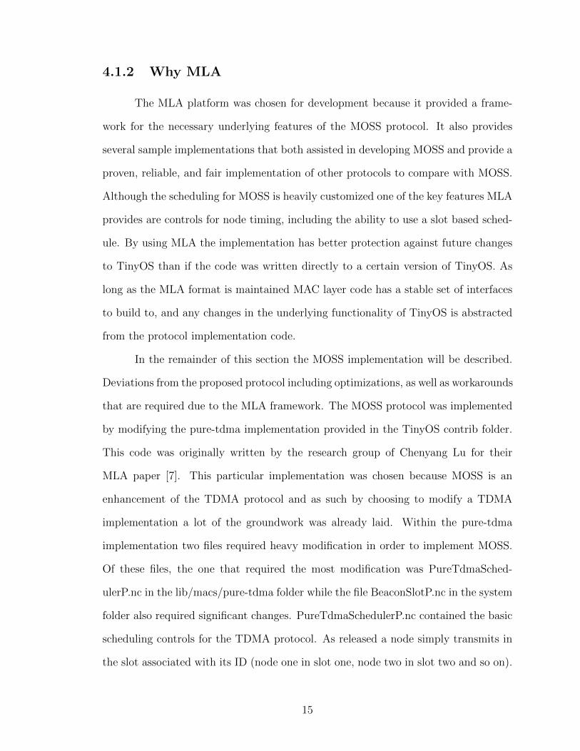


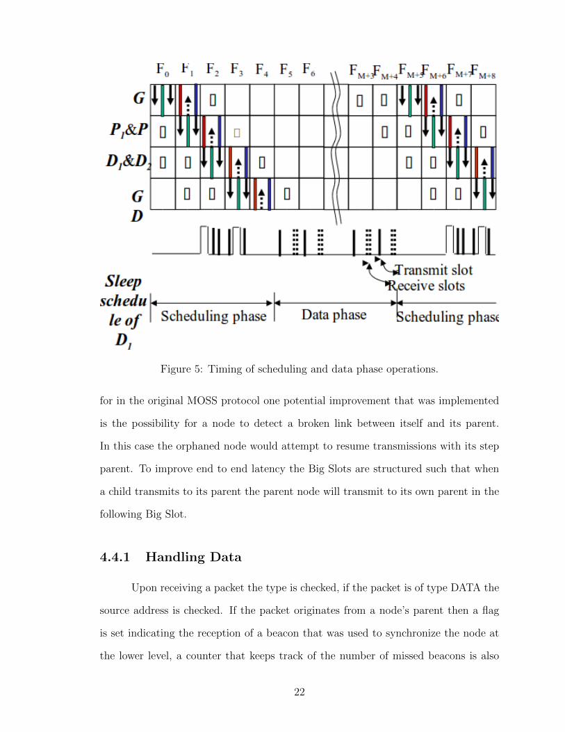


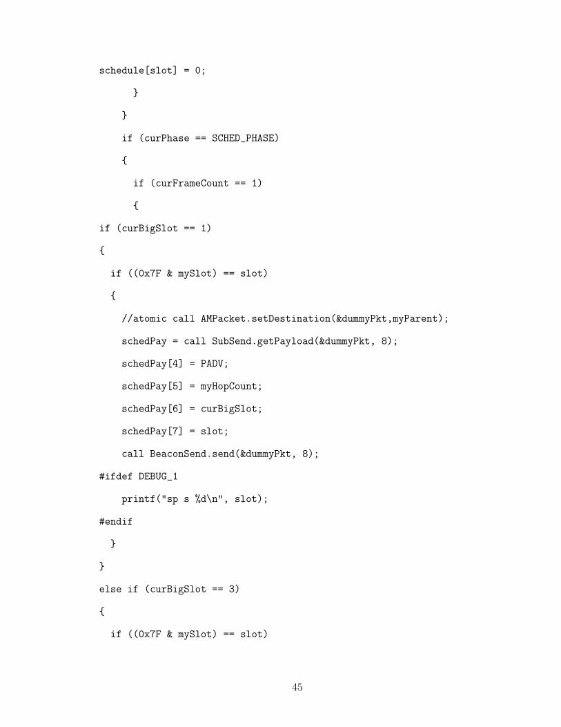


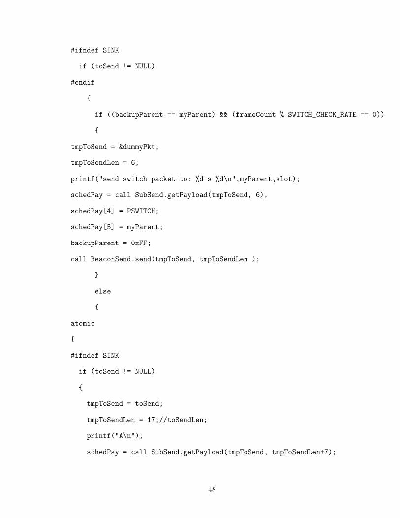


![Performance analysis of cellular CDMA high-speed data servicesbbcr.uwaterloo.ca/~wzhuang/papers/Kevin_WCM293.pdf · Designed as overlay on GSM/TDMA networks GPRS [2,3] 2.5G TDMA 0.2MHz](https://static.documents.pub/doc/80x56/5f07430d7e708231d41c1cec/performance-analysis-of-cellular-cdma-high-speed-data-wzhuangpaperskevinwcm293pdf.jpg)