152
[1]Oracle® Communications Network Service Orchestration Implementation Guide Release 7.3.5 E80746-01 February 2017

[1] Oracle® Communications Network Service OrchestrationImplementation Guide
Release 7.3.5
E80746-01
February 2017

Oracle Communications Network Service Orchestration Implementation Guide, Release 7.3.5
E80746-01
Copyright © 2017, Oracle and/or its affiliates. All rights reserved.
This software and related documentation are provided under a license agreement containing restrictions on use and disclosure and are protected by intellectual property laws. Except as expressly permitted in your license agreement or allowed by law, you may not use, copy, reproduce, translate, broadcast, modify, license, transmit, distribute, exhibit, perform, publish, or display any part, in any form, or by any means. Reverse engineering, disassembly, or decompilation of this software, unless required by law for interoperability, is prohibited.
The information contained herein is subject to change without notice and is not warranted to be error-free. If you find any errors, please report them to us in writing.
If this is software or related documentation that is delivered to the U.S. Government or anyone licensing it on behalf of the U.S. Government, then the following notice is applicable:
U.S. GOVERNMENT END USERS: Oracle programs, including any operating system, integrated software, any programs installed on the hardware, and/or documentation, delivered to U.S. Government end users are "commercial computer software" pursuant to the applicable Federal Acquisition Regulation and agency-specific supplemental regulations. As such, use, duplication, disclosure, modification, and adaptation of the programs, including any operating system, integrated software, any programs installed on the hardware, and/or documentation, shall be subject to license terms and license restrictions applicable to the programs. No other rights are granted to the U.S. Government.
This software or hardware is developed for general use in a variety of information management applications. It is not developed or intended for use in any inherently dangerous applications, including applications that may create a risk of personal injury. If you use this software or hardware in dangerous applications, then you shall be responsible to take all appropriate fail-safe, backup, redundancy, and other measures to ensure its safe use. Oracle Corporation and its affiliates disclaim any liability for any damages caused by use of this software or hardware in dangerous applications.
Oracle and Java are registered trademarks of Oracle and/or its affiliates. Other names may be trademarks of their respective owners.
Intel and Intel Xeon are trademarks or registered trademarks of Intel Corporation. All SPARC trademarks are used under license and are trademarks or registered trademarks of SPARC International, Inc. AMD, Opteron, the AMD logo, and the AMD Opteron logo are trademarks or registered trademarks of Advanced Micro Devices. UNIX is a registered trademark of The Open Group.
This software or hardware and documentation may provide access to or information about content, products, and services from third parties. Oracle Corporation and its affiliates are not responsible for and expressly disclaim all warranties of any kind with respect to third-party content, products, and services unless otherwise set forth in an applicable agreement between you and Oracle. Oracle Corporation and its affiliates will not be responsible for any loss, costs, or damages incurred due to your access to or use of third-party content, products, or services, except as set forth in an applicable agreement between you and Oracle.
iii
Contents
Preface ................................................................................................................................................................ vii
Audience...................................................................................................................................................... viiRelated Documentation............................................................................................................................. viiDocumentation Accessibility ................................................................................................................... viii
1 Overview
About Network Service Orchestration................................................................................................. 1-1Network Service Orchestration Components ..................................................................................... 1-2About Network Service Orchestration Entities.................................................................................. 1-2About the UIM User Interface ............................................................................................................... 1-4
About UIM Help ................................................................................................................................ 1-5About the Sample Network Services ................................................................................................... 1-5
2 Setting Up Network Service Orchestration
Planning Your Implementation............................................................................................................. 2-1Software Requirements........................................................................................................................... 2-1Migrating Network Service Orchestration 7.3.4 Cartridges............................................................. 2-2Installing and Integrating the Network Service Orchestration Components .............................. 2-2Integrating Network Service Orchestration With Northbound Applications for Asynchronous Communication ........................................................................................................................................ 2-2Integrating the VIM with Network Service Orchestration .............................................................. 2-3
Registering the VIM........................................................................................................................... 2-4Discovering VIM Resources ............................................................................................................. 2-4
Setting Network Service Orchestration Properties ........................................................................... 2-5Enabling Logging for Network Service Orchestration ..................................................................... 2-6Supported Southbound Integration ..................................................................................................... 2-6
3 Designing and Onboarding Network Services, VNFs, and PNFs
About Design Components .................................................................................................................... 3-1About Descriptor Files....................................................................................................................... 3-1
About Network Service Descriptor Files................................................................................. 3-2About VNF Descriptor Files ................................................................................................... 3-11About PNF Descriptor Files ................................................................................................... 3-19Creating a Descriptor File ....................................................................................................... 3-20
About Technical Actions Files....................................................................................................... 3-20

iv
Creating a Technical Actions File .......................................................................................... 3-23About VNF Configuration Files.................................................................................................... 3-23
Setting Network Service Descriptor Properties .............................................................................. 3-24Onboarding Network Services and VNFs Using TOSCA Descriptor Templates .................... 3-26
Sample TOSCA VNF Descriptor Template ................................................................................. 3-27Sample TOSCA Network Service Descriptor Template ............................................................ 3-29Installing Python ............................................................................................................................. 3-31Importing the TOSCA VNFD Template into Design Studio .................................................... 3-32
Tagging Network Service Orchestration Specifications ............................................................... 3-33Designing Custom Network Services ............................................................................................... 3-33
Creating Cartridges for VNFs ....................................................................................................... 3-34Logical Device Specification................................................................................................... 3-34Service Specification ................................................................................................................ 3-36Service Configuration Specification ...................................................................................... 3-37
Creating Cartridges for PNFs........................................................................................................ 3-38Logical Device Specification................................................................................................... 3-38Service Specification ................................................................................................................ 3-39Service Configuration Specification ...................................................................................... 3-40
Creating Cartridges for Network Services .................................................................................. 3-41Network Service Specification ............................................................................................... 3-41Network Service Configuration Specification ..................................................................... 3-43
4 Working with Network Services, VNFs, VDUs, and PNFs
Instantiating Network Services ............................................................................................................. 4-1Managing Failed Life-Cycle Actions ............................................................................................... 4-3
Accepting Partially Instantiated Network Services ............................................................... 4-3Rolling Back Partially Instantiated Network Services........................................................... 4-4Adding Failed VNFs to Partially Instantiated Network Services........................................ 4-4
Modifying Network Services................................................................................................................. 4-4Adding VNFs to Existing Network Services.................................................................................. 4-5Removing VNFs from Existing Network Services ........................................................................ 4-5
Terminating Network Services.............................................................................................................. 4-5Viewing Progress of Life-cycle Actions ............................................................................................... 4-6Scaling VNFs ............................................................................................................................................. 4-6Healing VNFs............................................................................................................................................ 4-7
Monitoring VNFs ............................................................................................................................... 4-7About the Monitoring Tabs in the User Interface ......................................................................... 4-8
Working with PNFs in Network Services ........................................................................................... 4-8Retrieving Details About Network Services, VNFs, PNFs, and Descriptors ............................... 4-8Registering VNFs with Third-Party Systems ..................................................................................... 4-9
5 Implementing the Sample Network Services
Configuring the Juniper vSRX Base Image......................................................................................... 5-1Implementing the Network Protection Service.................................................................................. 5-4Implementing the Residential Gateway Network Service .............................................................. 5-5Implementing the Proxy-Call Session Control Function Network Service.................................. 5-7Integrating Network Service Orchestration with IP Service Activator ........................................ 5-9
v
Setting Juniper_vSRX Sample Cartridge Properties .................................................................. 5-10
6 Extending Network Service Orchestration
Setting Up Design Studio for Extending Network Service Orchestration ................................... 6-1Using Extension Points and Java Interface Extensions to Extend Network Service Orchestration . 6-2
Writing a Custom Ruleset Extension Point .................................................................................... 6-2Using Java Interface Extensions....................................................................................................... 6-3
Implementing a Custom SDN Controller................................................................................ 6-4Implementing a Custom Monitoring Engine.......................................................................... 6-6Implementing a Custom VIM ................................................................................................... 6-7Implementing a Custom VNF Life Cycle Manager ............................................................... 6-8Implementing an Adapter for a Custom VNF Manager....................................................... 6-9Implementing a Custom VNF Connection Manager.......................................................... 6-10Implementing a Custom VNF Configuration Manager ..................................................... 6-12Implementing a Custom Response Manager....................................................................... 6-13Implementing a Custom Notification Manager ................................................................. 6-13
Localizing Network Service Orchestration ...................................................................................... 6-14Localizing the Responses in RESTful APIs.................................................................................. 6-14
7 Network Service Orchestration RESTful API Reference
About the Network Service Orchestration RESTful APIs ............................................................... 7-1Network Service Orchestration RESTful API Resources ................................................................. 7-2RESTful API Responses.......................................................................................................................... 7-3Sample Requests and Responses .......................................................................................................... 7-5
Register VIM ....................................................................................................................................... 7-5Discover VIM Resources ................................................................................................................... 7-6Update VIM ........................................................................................................................................ 7-7Get VIM Details .................................................................................................................................. 7-8Instantiate Network Service ............................................................................................................. 7-9Get Network Services ..................................................................................................................... 7-12Get Network Service Details ......................................................................................................... 7-13Get Network Service VNFs............................................................................................................ 7-16Get Network Service Networks .................................................................................................... 7-18Get Network Service End Points................................................................................................... 7-19Get Network Service Status ........................................................................................................... 7-20Terminate Network Service ........................................................................................................... 7-21Add VNF to Network Service ....................................................................................................... 7-23Terminate VNF in a Network Service .......................................................................................... 7-25Heal VNF.......................................................................................................................................... 7-27Scale VNF ......................................................................................................................................... 7-31Get VNF Details............................................................................................................................... 7-34Get VNF Status ................................................................................................................................ 7-36Heal VDU ......................................................................................................................................... 7-36Register PNF .................................................................................................................................... 7-37Update PNF...................................................................................................................................... 7-38

vi
Get PNFs........................................................................................................................................... 7-39Get PNF Details ............................................................................................................................... 7-40Unregister PNF................................................................................................................................ 7-40Register EMS.................................................................................................................................... 7-41Update EMS ..................................................................................................................................... 7-42Get EMSs .......................................................................................................................................... 7-42Get EMS Details............................................................................................................................... 7-43Unregister EMS................................................................................................................................ 7-44Get Network Service Descriptors ................................................................................................. 7-44Get Network Service Descriptor Details...................................................................................... 7-45Get Network Service Descriptor VNFDs..................................................................................... 7-47Get Network Service Descriptor Flavors ..................................................................................... 7-48Get VNF Descriptor Details ........................................................................................................... 7-49Get VNF Descriptor Flavors .......................................................................................................... 7-51

vii
Preface
This guide explains how to implement and use Oracle Communications Network Service Orchestration.
AudienceThis document is intended for:
■ Network operations and management personnel who install, configure, and maintain physical and virtual network infrastructure
■ Data modelers who define specifications for entities that represent Virtual Network Functions (VNFs), network services, and other related and dependant items in the inventory
■ Engineers who model resources in Design Studio
■ Systems integrators who implement and integrate Oracle Communications Unified Inventory Management (UIM) and third-party software as part of Network Service Orchestration
The guide assumes that you have a working knowledge of UIM and Network Functions Virtualization (NFV) architecture and concepts.
Related DocumentationFor step-by-step instructions to perform tasks, log in to each application to see the following:
■ UIM Help: Provides step-by-step instructions for tasks you perform in UIM.
■ Design Studio Help: Provides step-by-step instructions for tasks you perform in Design Studio.
For more information, see the following documentation:
■ UIM Installation Guide: Describes the requirements for installing UIM, installation procedures, and post-installation tasks.
■ UIM System Administrator’s Guide: Describes administrative tasks such as working with cartridge packs, maintaining security, managing the database, configuring Oracle Map Viewer, and troubleshooting.
■ Design Studio Installation Guide: Describes the requirements for installing Design Studio, installation procedures, and post-installation tasks.
■ UIM Security Guide: Provides guidelines and recommendations for setting up UIM in a secure configuration.

viii
■ UIM Concepts: Provides an overview of important concepts and an introduction to using both UIM and Design Studio.
■ UIM Developer’s Guide: Explains how to customize and extend many aspects of UIM, including the data model, life-cycle management, topology, security, rulesets, user interface, and localization.
■ Design Studio Developer’s Guide: Describes how to customize, extend, and work with cartridges.
■ UIM Web Services Developer’s Guide: Describes the UIM Web Service operations and how to use them, and describes how to create custom Web services.
■ UIM Information Model Reference: Describes the UIM information model entities and data attributes, and explains patterns that are common across all entities. This document is available on the Oracle Software Delivery Cloud as part of the Oracle Communications Unified Inventory Management Developer Documentation package.
■ Oracle Communications Information Model Reference: Describes the Oracle Communications information model entities and data attributes, and explains patterns that are common across all entities. The information described in this reference is common across all Oracle Communications products. This document is available on the Oracle Software Delivery Cloud as part of the Oracle Communications Unified Inventory Management Developer Documentation package.
■ UIM Cartridge Guide: Provides information about how you use cartridge packs with UIM. Describes the content of the base cartridges.
Documentation AccessibilityFor information about Oracle's commitment to accessibility, visit the Oracle Accessibility Program website at http://www.oracle.com/pls/topic/lookup?ctx=acc&id=docacc.
Access to Oracle SupportOracle customers that have purchased support have access to electronic support through My Oracle Support. For information, visit http://www.oracle.com/pls/topic/lookup?ctx=acc&id=info or visit http://www.oracle.com/pls/topic/lookup?ctx=acc&id=trs if you are hearing impaired.

1
Overview 1-1
1Overview
This chapter provides an overview of Oracle Communications Network Service Orchestration.
About Network Service OrchestrationOracle Communications Network Service Orchestration is a functional module of Oracle Communications Unified Inventory Management (UIM). You use Network Service Orchestration to model network services, Virtual Network Functions (VNFs), and Physical Network Functions (PNFs). You also use Network Service Orchestration to manage the life cycles of network services and VNFs.
Network Service Orchestration enables you to create, implement, and manage the life cycles of network services and deploy the network services as interconnected VNFs and PNFs on virtual resources.
Network Service Orchestration enables you to model a VNF that is composed of multiple internal components called Virtual Network Function Components (VNFCs), that you can deploy on multiple Virtual Deployment Units (VDUs). You deploy the VDUs as virtual machines (VMs) in the NFV Infrastructure (NFVI), thus enabling you to design and deploy large, complex VNFs across multiple VMs. See "About VNF Descriptor Files" for more information.
Network Service Orchestration provides the following functionality:
■ Onboarding of Network Services, VNFs, and PNFs. You can define network services, VNFs, and PNFs based on any network function that you want to virtualize. See "Designing and Onboarding Network Services, VNFs, and PNFs" for more information.
■ Instantiation and Termination of Network Services. You can quickly instantiate and terminate VNFs and network services in response to demand on your network. You can manage the life cycles of your VNFs and network services and control the resources that they use. See "Working with Network Services, VNFs, VDUs, and PNFs" for more information.
■ Scaling of VNFs. You can scale VNFs when the existing resources assigned to a VNF are unable to provide the expected quality of service, so it is necessary to add additional resources to meet the needs of the VNF and to maintain the quality of service. See "Scaling VNFs" for more information.
■ Healing VNFs. You can heal a VNF when the VNF fails to perform at the expected performance level. See "Healing VNFs" for more information.
■ Resource Orchestration. Network Service Orchestration manages the resources across your data centers to ensure that each network service is allocated the

Network Service Orchestration Components
1-2 Network Service Orchestration Implementation Guide
required resources to meet the needs of the VNFs. See "Working with Network Services, VNFs, VDUs, and PNFs" for more information.
■ Asynchronous communication with northbound applications. Network Service Orchestration supports asynchronous communication with northbound applications. See "Integrating Network Service Orchestration With Northbound Applications for Asynchronous Communication" for more information.
■ Viewing Progress of Life-cycle Actions. You can view notifications that indicate the progress of the life-cycle actions that you perform on the network service and its constituent VNFs. See "Viewing Progress of Life-cycle Actions" for more information.
■ Customization and Extension. You can customize and extend Network Service Orchestration to support integration with third-party VNF Managers, Virtualized Infrastructure Managers (VIMs), software-defined networking (SDN) controllers, and monitoring engines. Network Service Orchestration also provides extension points that enable you to customize and extend its core functionality. See "Extending Network Service Orchestration" for more information.
Network Service Orchestration ComponentsNetwork Service Orchestration builds on Oracle Communications Unified Inventory Management (UIM), taking advantage of its inventory and workflow capabilities to perform run-time orchestration of Network Functions Virtualization (NFV) environments, including virtual, physical, and hybrid networks.
Oracle Communications Design Studio provides the design-time environment for onboarding VNFs and composing network services. Network Service Orchestration is extensible and allows integration with third-party VNF managers, VIMs, monitoring engines, and SDN Controllers.
Network Service Orchestration includes a VNF Manager that enables you to manage the life cycles of the VNFs. Network Service Orchestration also supports integration with Oracle and third-party VNF Managers, VIMs, SDN controllers, and network monitoring applications. By default, Network Service Orchestration provides integration to certain applications and supports integration to additional applications during the implementation.
Network Service Orchestration provides RESTful APIs, which communicate over HTTP and HTTPS, to interact and exchange data between various components.
About Network Service Orchestration EntitiesNetwork Service Orchestration uses the Oracle Communications Information Model (OCIM) to represent inventory items and business practices. The Oracle Communications Information Model is based on the Shared Information Data (SID) model developed by the TeleManagement Forum. The information model contains resource entities, service entities, common patterns, definitions, and common business entities.
For details about the Oracle Communications Information Model (OCIM), see Oracle Communications Information Model Reference and UIM Information Model Reference.
Table 1–1 describes the NFV entities and their corresponding OCIM entities.

About Network Service Orchestration Entities
Overview 1-3
Table 1–1 Mapping of NFV Entities and OCIM Entities
NFV Entity OCIM Entity Description
Availability Zone Custom Object with characteristics.
Represents a grouping of resources based on availability characteristics, for example, Availability Zone (OpenStack). In OpenStack, availability zones enable you to arrange OpenStack compute hosts into logical groups and provides a form of physical isolation and redundancy from other availability zones, such as by using a separate power supply or network equipment.
Connection Point Device Interface Represents a port on the VNF. Connection points connect Virtual Links to VNFs. They represent the virtual interfaces and physical interfaces of the VNFs and their associated properties and other metadata
Deployment Flavor Custom Object Represents a specific deployment of a network service or VNF supporting specific key performance indicators (KPIs), such as capacity and performance.
Element Management System (EMS)
Custom Object Represents the Element Management System, which performs the typical management functionality for one or several VNFs.
Endpoint Custom Object Describes a service access point for the network service.
Flavor Custom Object Defines the compute, memory, and storage capacity of computing instances. A flavor is an available hardware configuration for a server. It defines the size of a virtual server that can be launched.
Host Custom Object with characteristics.
Represents a compute host, a physical host dedicated to running compute nodes.
Infrastructure Domain Network Address Domain Represents the domain within the NFV Infrastructure that includes all networking that interconnects compute and storage infrastructure.
IP Network Infrastructure ■ Network Address Domain
■ IP Network
■ IP Subnet
■ IP Address
Represents the network, subnet, and IP address of the VNF in Network Service Orchestration.
The networks are either created or referenced in the service configuration. During activation, the corresponding network, subnet, and ports are created in the VIM on which the VNF virtual machine is deployed.
IP Address IP Address Represents an IPv4Address and an IPv6Address in the OCIM domain model.
Network Service Service Represents a composition of network functions.
Network Service Descriptor
■ Service Specification
■ Service Config Version Specification
Describes a network service in terms of its deployment and operational behavior. Used in the process of network service on-boarding and managing the life cycle of a network service instance.
Orchestration Request Business Interaction Represents an NFV life-cycle action in UIM. Every time you perform a life-cycle action, Network Service Orchestration creates a business interaction for the action in UIM.
Physical Network Function (PNF)
Logical Device Service Represents an implementation of a network function that is a tightly-coupled hardware and software system. A network function is a functional building block within a network infrastructure that has well-defined external interfaces and a well-defined functional behavior.

About the UIM User Interface
1-4 Network Service Orchestration Implementation Guide
About the UIM User InterfaceThe UIM user interface provides a group of links and pages for performing network service and VNF life cycle operations and for managing your data center resources.
The UIM user interface displays the Network Service Orchestration group in the navigation section that includes the following expandable and collapsible subgroups of links:
■ In the Orchestration subgroup:
– Orchestration Requests. Clicking this link displays the Search page for orchestration requests. From the Search page, you can create new orchestration requests. The Search page also returns service requests that are created based on your NFV service request specifications.
PNF Descriptor ■ Logical Device Specification
■ Service Specification
■ Service Config Version Specification
Describes a PNF in terms of its deployment and operational behavior. The PNF Descriptor is used for onboarding PNFs.
SDN Controller Custom Object Centralizes some or all of the control and management functionality of a network domain. An SDN controller can also provide an abstract view of its domain to other functional components through well-defined interfaces.
Subnet IP Subnet Represents an administrative or functional boundary on a range of network addresses. A subnet is defined by a base range whose sequence is often appended to a fixed prefix.
Virtual Data Center (VDC) Custom Object with characteristics.
Represents the resources managed by a VIM under a specific tenant (for example, OpenStack).
Virtual Link IP Network Describes the basic topology of connectivity between VNFs and target parameters, such as bandwidth, latency, and QoS. Virtual links connect to VNFs using Connection Points (CPs).
Virtual Network Function (VNF)
■ Logical Device
■ Logical Device Service
■ Service Config Version
Represents an implementation of a network function that can be deployed on a Network Function Virtualization Infrastructure (NFVI). A network function is a functional building block within a network infrastructure that has well-defined external interfaces and a well-defined functional behavior.
Virtual Deployment Unit (VDU)
Logical Device Represents a virtual machine that hosts a single or multiple components of a VNF.
Virtualized Infrastructure Manager (VIM)
Custom Object with characteristics.
Represents a functional component that is responsible for controlling and managing the NFVI compute, storage and network resources, usually within an operator's infrastructure domain.
VNF Descriptor ■ Logical Device Specification
■ Service Specification
■ Service Config Version Specification
Describes a VNF in terms of its deployment and operational behavior. The VNF Descriptor is used in the process of VNF onboarding and managing the life cycle of a VNF instance.
Table 1–1 (Cont.) Mapping of NFV Entities and OCIM Entities
NFV Entity OCIM Entity Description

About the Sample Network Services
Overview 1-5
– Network Services. Clicking this link displays the Search page for network services. From the Search page, you can create new network services. The Search page also returns a list of network services that are created based on your network service descriptors.
– VNFs. Clicking this link displays the Search page for VNFs. The search page returns a list of VNFs that are created based on your VNF descriptors.
■ In the Catalog subgroup:
– Network Service Descriptors. Clicking this link displays the Search page for Network Service descriptors. From the Search page, you can create and instantiate new network services. The search page also returns a list of network service descriptors.
– VNF Descriptors. Clicking this link displays the Search page for VNF descriptors. The search page returns a list of VNF descriptors.
See the chapter on “UIM User Interface Overview” in UIM Concepts for more information about the user interface. See the UIM Help for instructions about performing tasks related to network services, VNFs, and PNFs.
About UIM HelpUIM includes a Help system that you use to get step-by-step instructions. You can find the information you need by searching or by navigating through the table of contents. See the section on “Using the UIM Help” in the chapter, “UIM User Interface Overview” in UIM Concepts for more information about the UIM Help system.
About the Sample Network ServicesNetwork Service Orchestration includes the following sample cartridges that you can use as references for designing and implementing your own network services:
■ Juniper_vSRX. This sample cartridge contains the Juniper vSRX firewall VNF to use with the network protection service.
■ Checkpoint_NG_FW. This sample cartridge contains the Checkpoint firewall VNF to use with the network protection service.
■ Cisco_xRV. This sample cartridge contains the Cisco XRV router PNF to use with the residential gateway network service.
■ OracleComms_SBC. This sample cartridge contains the Session Border Controller (SBC) VNF to use with the Proxy-Call Session Control Function (P-CSCF) network service.
■ NPaaS_NetworkService. This sample cartridge contains the functionality to implement network protection as a service.
■ ResidentialGateway_NetworkService. This sample cartridge contains the functionality to implement a residential gateway service.
■ OracleComms_P-CSCF_NetworkService. This sample cartridge provides the functionality to implement a Proxy-Call Session Control Function (P-CSCF) network service.
See "Implementing the Sample Network Services" for detailed information about the sample network services.

About the Sample Network Services
1-6 Network Service Orchestration Implementation Guide

2
Setting Up Network Service Orchestration 2-1
2Setting Up Network Service Orchestration
This chapter describes the instructions for setting up Oracle Communications Network Service Orchestration.
Planning Your ImplementationBefore you implement Network Service Orchestration, you must identify the required software, ensure that the required network infrastructure is available and ready, and identify the third-party software that you want to use. Your choices are based on the network services you want to deliver on your network.
Use the following list of tasks as a checklist to ensure that you have all the required components for a successful implementation of Network Service Orchestration:
■ Install and integrate the Network Service Orchestration components. See "Software Requirements" and "Installing and Integrating the Network Service Orchestration Components".
■ Integrate your Virtual Infrastructure Manager (VIM). See "Integrating the VIM with Network Service Orchestration".
■ Onboard Network Services and VNFs. See "Designing and Onboarding Network Services, VNFs, and PNFs".
■ Write extensions for extending the core functionality and integrate third-party software with Network Service Orchestration. See "Using Extension Points and Java Interface Extensions to Extend Network Service Orchestration".
■ Integrate client applications with Network Service Orchestration for using the RESTful APIs. For details about the RESTful APIs, see "Network Service Orchestration RESTful API Reference".
Software RequirementsTo implement Network Service Orchestration, you require the following software:
■ Oracle Communications Unified Inventory Management 7.3.5.
See UIM Installation Guide for installation instructions.
■ Oracle Communications Design Studio 7.3.5.
See Design Studio Installation Guide for installation instructions.

Migrating Network Service Orchestration 7.3.4 Cartridges
2-2 Network Service Orchestration Implementation Guide
Migrating Network Service Orchestration 7.3.4 CartridgesIf you are using Network Service Orchestration 7.3.4 VNF and network service cartridges, you must migrate your 7.3.4 cartridges to 7.3.5 to take advantage of the improved functionality introduced in Network Service Orchestration 7.3.5.
For detailed instructions, see Knowledge Article 2231188.1 - How To Migrate NSO 7.3.4 Cartridges To Network Service Orchestration 7.3.5 on the My Oracle Support website:
https://support.oracle.com
Installing and Integrating the Network Service Orchestration ComponentsTo install and integrate the Network Service Orchestration components:
1. Install UIM on a WebLogic server. See UIM Installation Guide for installation instructions.
2. Navigate to the UIM_Home/cartridges/base directory and deploy the following UIM cartridges into UIM in the order they are listed:
■ ora_uim_baseextpts
■ ora_uim_basemeasurements
■ ora_uim_basetechnologies
■ ora_uim_basespecifications
■ ora_uim_baserulesets
■ OracleComms_NSO_BaseCartridge
See UIM Cartridge Guide for instructions about deploying cartridges into UIM.
3. (Optional) If you want to use the sample cartridges that are provided with Network Service Orchestration, navigate to the UIM_Home/cartridges/sample directory and deploy the sample cartridges into UIM.
See "About the Sample Network Services" for more information about the sample cartridges provided with Network Service Orchestration.
See "Implementing the Sample Network Services" for information about implementing the sample network services.
4. (Optional) Integrate Network Service Orchestration with northbound applications for asynchronous communication. See "Integrating Network Service Orchestration With Northbound Applications for Asynchronous Communication".
5. Integrate the VIM with Network Service Orchestration. See "Integrating the VIM with Network Service Orchestration" for more information.
Integrating Network Service Orchestration With Northbound Applications for Asynchronous Communication
Some VNF and network service life cycle operations perform long-running processes. Network Service Orchestration supports integration with northbound applications in asynchronous communication for such life cycle operations.
Note: Before deploying the sample cartridges, deploy the ora_uim_common cartridge.

Integrating the VIM with Network Service Orchestration
Setting Up Network Service Orchestration 2-3
With this integration, Network Service Orchestration provides the final and actual status of the following life-cycle actions so that northbound systems can perform and complete service fulfillment:
■ Instantiate a network service
■ Terminate a network service
■ Add one or more VNFs to network service
■ Delete one or more VNFs from a network service
■ Scale a VNF
■ Reboot a VNF
■ Replace a VNF
■ Reboot a VDU
To integrate Network Service Orchestration with northbound systems for asynchronous communication:
1. Configure your client applications to subscribe to the NSOResponseTopic topic in the WebLogic server. During installation, UIM creates the JMS Module and NSOResponseTopic.
You can implement a custom response topic and configure your applications to subscribe to it. See "Implementing a Custom Response Manager" for more information about implementing a custom response topic.
2. On the WebLogic server, in the JMS Module, create a Durable Subscriber under NSOResponseTopic to capture the messages.
3. Open the UIM_Home/config/nso.properties file and uncomment the following property:
#nso.ResponseManager.list.1=oracle.communications.inventory.nso.client.vnfm.NSOResponseTopicImpl
Integrating the VIM with Network Service OrchestrationNetwork Service Orchestration supports OpenStack and provides integration points for integrating other third-party VIMs. See "Implementing a Custom VIM" for more information about implementing a custom VIM.
Before you integrate the VIM with Network Service Orchestration, ensure that you set up and configure the VIM to use with Network Service Orchestration. After your VIM infrastructure is set up, register the VIM and discover the VIM resources into Network Service Orchestration.
Integrating the VIM with Network Service Orchestration involves the following tasks:
■ Registering the VIM
■ Discovering VIM Resources
Note: If you use multiple VIMs, register all of them with Network Service Orchestration and discover resources.

Integrating the VIM with Network Service Orchestration
2-4 Network Service Orchestration Implementation Guide
Registering the VIMTo register a VIM with Network Service Orchestration:
1. Ensure that UIM is started and running.
2. Ensure that the required Network Service Orchestration base cartridges are deployed into UIM.
3. Ensure that the VIM is running and that you have the IP address, username, password, and other details of the VIM instance.
4. In a RESTful API client, call the following RESTful API using the POST method:
POST http://nso_host:port/ocnso/1.1/vim
where:
■ nso_host is the IP address of the machine on which UIM is installed
■ port is the port number of the machine on which UIM is installed
5. Specify the VIM details in the request. For details about the request parameters, see "Register VIM".
The RESTful API client returns a response.
6. In UIM, verify that a custom object with the details of the VIM is created.
Discovering VIM ResourcesYou discover VIM resources into UIM so that Network Service Orchestration contains information about the current status and availability of all the required virtual resources on the network. In UIM, VIMs are represented as custom objects.
When you discover VIM resources, the details of the following resources are populated into UIM:
■ Availability zone (OpenStack)
■ Flavor
■ Host
■ Networks and Subnets
To discover VIM resources into UIM:
1. In a RESTful API client, call the following RESTful API using the POST method:
POST http://nso_host:port/ocnso/1.1/vim/vimId/discovery?infoLevel=vim_information
where:
■ nso_host is the IP address or the domain name of the machine on which UIM is installed
■ port is the port number of the machine on which UIM is installed
■ vimId is the Id of the VIM that you registered with Network Service Orchestration and whose resources you want to discover
■ vim_information is the level of information about the VIM that you want to retrieve and view in the response. The available values are:
– summary. Retrieves and displays a summary of the VIM resources.

Setting Network Service Orchestration Properties
Setting Up Network Service Orchestration 2-5
– details. Retrieves and displays complete details about all the VIM resources.
For more details about the request parameters, see "Discover VIM Resources".
The RESTful API client returns a response.
2. In UIM, verify that the following entities are created:
■ Availability zone
■ Flavor
■ Host
■ VDC
■ Network address domains
■ IP subnets
Setting Network Service Orchestration PropertiesNetwork Service Orchestration provides the UIM_Home/config/nso.properties file that you use to specify properties for your implementation of Network Service Orchestration.
To set the properties, open the nso.properties file in a text editor and update the following parameters:
■ NSO_HOST: IPv4address
where IPv4address is the host on which UIM is installed. By default, Network Service Orchestration considers the host on which the UIM server is running. If the server is running on a private network that is unavailable to external network, specify a reachable IP address for the server.
■ NSO_USERNAME: username
where username is the username of the UIM user.
■ NSO_PASSWORD: password
where password is the encrypted password of the UIM user.
To encrypt the password:
1. Create a text file and type the password.
2. Save and close the file.
3. In UIM, in the Administration group of the navigation section, click Execute Rulesets.
4. In the Ruleset list, select the EncryptText ruleset, and enter the path and file name of the text file that contains the password in plain text and click Process.
Note: Whenever you add, modify, or delete the compute, memory, and network resources in your NFV Infrastructure (NFVI), run the VIM discovery RESTful API to ensure that details about the currently available resources on your NFVI are reflected correctly in Network Service Orchestration.

Enabling Logging for Network Service Orchestration
2-6 Network Service Orchestration Implementation Guide
UIM displays the encrypted password. Copy the encrypted password and specify it in the nso.properties file.
Enabling Logging for Network Service OrchestrationYou enable logging for Network Service Orchestration to log debug messages.
For more information about logging, see the chapter about improving UIM performance in UIM System Administrator’s Guide.
To enable logging for Network Service Orchestration:
1. Open the UIM_Home/config/loggingconfig.xml file in a text editor.
2. Add the following text:
<logger name="oracle.communications.inventory.nso" additivity="false"> <level value="debug"/> <appender-ref ref="stdout"/> <appender-ref ref="rollingFile"/></logger>
3. Save and close the file.
Supported Southbound IntegrationNetwork Service Orchestration supports some integrations by default, while others require customization. Network Service Orchestration supports the following southbound integrations:
■ For Virtual Infrastructure Management:
– Integration to OpenStack Mitaka and Liberty releases
– Integration to Oracle OpenStack for Oracle Linux Release 3 Beta
– A framework for integration to other Virtual Infrastructure Managers
■ For Network and SDN controllers:
– Integration to OpenStack Neutron (Mitaka and Liberty releases)
– Integration to OpenStack Neutron Networking-SFC (Service Function Chaining)
■ For VNF management:
– Network Service Orchestration includes a built-in VNF Manager that supports the life-cycle management of VNFs. The VNF manager calls the VIM to perform life-cycle actions. The in-built VNF Manager supports direct integration to the VNF or integration to an Element Management System (EMS) that manages the VNF.
– A framework that supports integration to external VNF Managers.

3
Designing and Onboarding Network Services, VNFs, and PNFs 3-1
3Designing and Onboarding Network Services,VNFs, and PNFs
This chapter provides information about designing and onboarding network services, Virtual Network Functions (VNFs), and Physical Network Functions (PNFs).
About Design ComponentsDesign components are files that you create in Oracle Communications Design Studio. Network Service Orchestration uses different types of files that you create in Design Studio to describe the behavior of your network services, VNFs, and PNFs.
■ Descriptor files. The descriptor files describe the attributes of the VNF, PNF, and Network Service specifications.
See "About Descriptor Files" for more information about the descriptor files.
■ Technical actions files. The technical actions files describe the actions for the VNFs, PNFs, and network services in the VIM. There is one technical actions file for each network service, VNF, and PNF.
See "About Technical Actions Files" for more information about the technical actions files.
■ Configuration and template files. The configuration files contain the configuration and post-configuration details for the VNFs.
See "About VNF Configuration Files" for more information about the descriptor files.
■ Entity Specifications. In Design Studio, you create entity specifications that you use to create instances of VNFs and network services in Network Service Orchestration. You package the entity specifications into cartridges. You create one cartridge for each VNF, network service, and PNF. See "Designing Custom Network Services" for more information.
See Design Studio Help for information about creating entity specifications in Design Studio.
■ Custom extensions. See "Extending Network Service Orchestration" for information about implementing custom extensions.
About Descriptor FilesDescriptor files contain metadata about network services, VNFs, and PNFs. Network Service Orchestration defines descriptors as Design Studio specifications and uses these specifications to manage the life cycles of network services and VNFs.

About Design Components
3-2 Network Service Orchestration Implementation Guide
Descriptors describe the behavior of virtual network functions that are defined in the Network Service Orchestration cartridges. There is one descriptor file for each network service, VNF, and PNF.
About Network Service Descriptor FilesNetwork Service descriptor files describe the deployment requirements, operational behavior, and policies required by network services based on them. You use one descriptor file for each network service.
When you instantiate, scale, or terminate a network service, Network Service Orchestration deploys, scales, and undeploys the constituent VNFs based on the parameters and policies specified in the descriptor file.
You use the network service descriptor file to do the following:
■ Describe the descriptor information. See "Describing Descriptor Information" for more information.
■ Describe the VNF descriptor references. See "Describing VNF Descriptor References" for more information.
■ Describe the PNF descriptor references. See "Describing PNF Descriptor References" for more information.
■ Describe the networks by either creating them or by referencing existing networks and specifying network types. For each network, specify the VNF connection points that terminate on the network. See "Describing Networks" for more information.
■ Describe the service flavors for the network service. See "Describing Service Flavors" for more information.
■ Describe the endpoints that the network service can have. See "Describing Endpoints" for more information.
■ Describe the rules to determine how the network traffic is routed in the network service. See "Describing Rules" for more information.
■ Describe the policies and their mappings to the network forwarding paths (NFPs). See "Describing Policies" for more information.
■ Describe the VNF forwarding graphs (VNFFGs) that include one or more network forwarding paths (NFPs) that determine how network traffic is routed in a network service. See "Describing VNF Forwarding Graphs" for more information.
Describing Descriptor InformationIn the network service descriptor file, you describe descriptor information, such as descriptor ID, descriptor name, vendor name, and descriptor version.
The following text shows the elements that enable you to provide information about the network service descriptor XML file:
<nsd id="network_service_descriptor_id" name="network_service_descriptor_name"><vendor>vendor_name</vendor><version>descriptor_version</version>
Table 3–1 describes the parameters you specify to provide information about the network service descriptor XML file.

About Design Components
Designing and Onboarding Network Services, VNFs, and PNFs 3-3
The following text shows the elements that provide descriptor information in the NPaas.xml sample network service descriptor file:
<nsd id="NPaas" name="NPaas"><vendor>Oracle</vendor><version>1.0</version>
Describing VNF Descriptor ReferencesIn the network service descriptor file, you reference the descriptors of all the VNFs that you want to include in the network service.
You reference the VNF descriptors in the network service descriptor file as follows:
<vnfd-reference ref-id="vnf_descriptor_id"/>
where:
■ vnf_descriptor_id is the ID of the VNF descriptor that you want to include in the network service.
The following is an example of the vnfd-reference element in the NPaas.xml sample network service descriptor file:
<!-- Multiple VNFs are supported. --><vnfd-reference ref-id="Juniper_vSRX"/><vnfd-reference ref-id="Checkpoint_NG_FW"/>
Describing PNF Descriptor ReferencesIn the network service descriptor file, you reference the descriptors of all the PNFs that you want to include in the network service.
You reference the PNF descriptors in the network service descriptor file as follows:
<pnfd-reference ref-id="pnf_descriptor_id"/>
where:
■ pnf_descriptor_id is the ID of the PNF descriptor that you want to include in the network service.
The following is an example of the pnfd-reference element in the ResidentialGateway.xml sample network service descriptor file:
<!-- Multiple PNFs are supported. --><pnfd-reference ref-id="Cisco_xRV"/>
Describing NetworksIn the network service descriptor file, you define networks by creating them or by referencing existing networks and specifying their types. You represent networks as
Table 3–1 Descriptor Information Parameters
Parameter Description
network_service_descriptor_id
Specify a unique ID for the network service descriptor.
network_service_descriptor_name
Specify a name for the network service descriptor.
vendor_name Specify the name of the vendor.
descriptor_version Specify the version of the network service descriptor.
About Design Components
3-4 Network Service Orchestration Implementation Guide
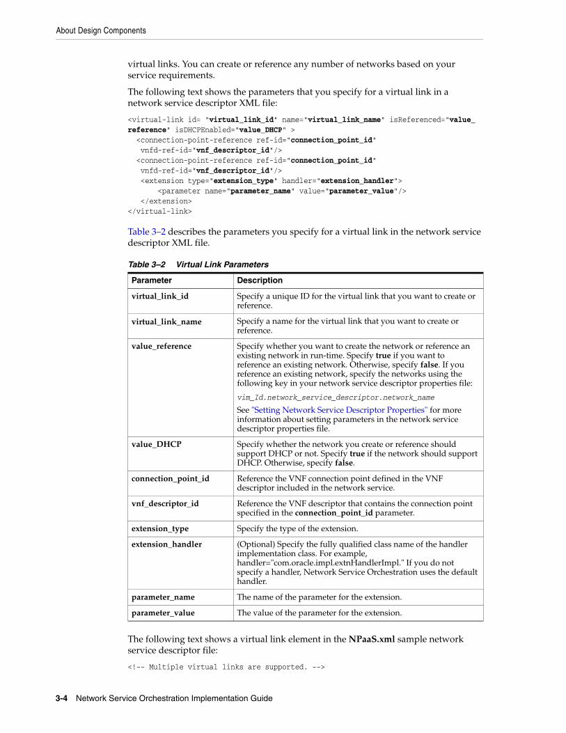
virtual links. You can create or reference any number of networks based on your service requirements.
The following text shows the parameters that you specify for a virtual link in a network service descriptor XML file:
<virtual-link id= "virtual_link_id" name="virtual_link_name" isReferenced="value_reference" isDHCPEnabled="value_DHCP" > <connection-point-reference ref-id="connection_point_id" vnfd-ref-id="vnf_descriptor_id"/> <connection-point-reference ref-id="connection_point_id" vnfd-ref-id="vnf_descriptor_id"/> <extension type="extension_type" handler="extension_handler"> <parameter name="parameter_name" value="parameter_value"/> </extension></virtual-link>
Table 3–2 describes the parameters you specify for a virtual link in the network service descriptor XML file.
The following text shows a virtual link element in the NPaaS.xml sample network service descriptor file:
<!-- Multiple virtual links are supported. -->
Table 3–2 Virtual Link Parameters
Parameter Description
virtual_link_id Specify a unique ID for the virtual link that you want to create or reference.
virtual_link_name Specify a name for the virtual link that you want to create or reference.
value_reference Specify whether you want to create the network or reference an existing network in run-time. Specify true if you want to reference an existing network. Otherwise, specify false. If you reference an existing network, specify the networks using the following key in your network service descriptor properties file:
vim_Id.network_service_descriptor.network_name
See "Setting Network Service Descriptor Properties" for more information about setting parameters in the network service descriptor properties file.
value_DHCP Specify whether the network you create or reference should support DHCP or not. Specify true if the network should support DHCP. Otherwise, specify false.
connection_point_id Reference the VNF connection point defined in the VNF descriptor included in the network service.
vnf_descriptor_id Reference the VNF descriptor that contains the connection point specified in the connection_point_id parameter.
extension_type Specify the type of the extension.
extension_handler (Optional) Specify the fully qualified class name of the handler implementation class. For example, handler="com.oracle.impl.extnHandlerImpl." If you do not specify a handler, Network Service Orchestration uses the default handler.
parameter_name The name of the parameter for the extension.
parameter_value The value of the parameter for the extension.

About Design Components
Designing and Onboarding Network Services, VNFs, and PNFs 3-5
<!-- isReferenced="true" means that network is not managed by Network Service Orchestration e.g. External networks in Provider Network --><virtual-link id="ManagementNetwork" name="ManagementNetwork" isReferenced="true" isDHCPEnabled="false"> <connection-point-reference ref-id="CP03" vnfd-ref-id="Juniper_vSRX"/> <connection-point-reference ref-id="CP03" vnfd-ref-id="Checkpoint_NG_FW"/></virtual-link>
<virtual-link id="Data_IN" name="Data_IN" isReferenced="false" isDHCPEnabled="false"> <connection-point-reference ref-id="CP01" vnfd-ref-id="Juniper_vSRX"/> <connection-point-reference ref-id="CP01" vnfd-ref-id="Checkpoint_NG_FW"/>
<!-- If no handler is provided, Network Service Orchestration will use its default VirtualLinkAddressHandler. --> <!-- Otherwise provide the fully qualified class name of the handler implementation class. e.g., handler="com.oracle.impl.VLHandlerImpl" --> <extension type="CreateVirtualLink"> <parameter name="subnetAddress" value="192.0.2.1/27"/> </extension></virtual-link> <virtual-link id="Data_OUT" name="Data_OUT" isReferenced="false" isDHCPEnabled="false"> <connection-point-reference ref-id="CP02" vnfd-ref-id="Juniper_vSRX"/> <connection-point-reference ref-id="CP02" vnfd-ref-id="Checkpoint_NG_FW"/> <extension type="CreateVirtualLink"> <parameter name="subnetAddress" value="192.0.2.21/30"/> </extension> </virtual-link>
Describing Service Flavors In the network service descriptor file, you can describe service flavors where in you specify constituent VNFs, reference the VNF deployment flavors defined for the constituent VNFs in their respective VNF descriptors, and specify the minimum and maximum VNF instances that must be included in the network service.
The following text shows the pattern in which you describe the service flavors in a network service descriptor file.
<service-flavor id="service_flavor_id" name="service_flavor_name"> <constituent-vnfd> <vnfd-reference ref-id="vnf_descriptor_id"/> <deployment-flavor-reference ref-id="vnf_deployment_flavor_id"/> <min-instances>min_vnf_instances</min-instances> <max-instances>max_vnf_instances</max-instances> </constituent-vnfd></service-flavor>
Table 3–3 describes the parameters you specify for a service flavor in the network service descriptor XML file.
Table 3–3 Service Flavor Parameters
Parameter Description
service_flavor_id Specify a unique ID for the network service flavor.
service_flavor_name Specify a name for the network service flavor.

About Design Components
3-6 Network Service Orchestration Implementation Guide
The following text shows a service flavor element in the NPaaS.xml sample network service descriptor file:
<service-flavor id="Checkpoint" name="Checkpoint"><!-- Multiple VNFs are supported.> <constituent-vnfd> <vnfd-reference ref-id="Checkpoint_NG_FW"/> <deployment-flavor-reference ref-id="premium"/> <min-instances>1</min-instances> <max-instances>1</max-instances> </constituent-vnfd></service-flavor>
<service-flavor id="Juniper" name="Juniper"> <constituent-vnfd> <vnfd-reference ref-id="Juniper_vSRX"/> <deployment-flavor-reference ref-id="standard"/> <min-instances>1</min-instances> <max-instances>1</max-instances> </constituent-vnfd></service-flavor>
Describing EndpointsIn the network service descriptor file, you can specify the number of endpoints the networks can have.
The following text shows the pattern in which you describe the network service endpoints in a network service descriptor file.
<endpoint id="endpoint_id" name="endpoint_name" <type>endpoint_type</type> <vld-reference ref-id="virtual_link_descriptor_id"/> <connection-point-reference ref-id="connection_point_id" vnfd-ref-id="vnf_descriptor_id"/></endpoint>
Table 3–4 describes the parameters you specify for network service endpoints in the network service descriptor XML file.
vnf_descriptor_id Reference the VNF descriptor that you want to use for this network service flavor.
vnf_deployment_flavor_id
Reference the VNF deployment flavor defined within the VNF descriptor.
min_vnf_instances Specify the minimum number of VNF instances that the network service flavor must include.
max_vnf_instances Specify the maximum number of VNF instances that the network service flavor can include.
Table 3–4 Endpoint Parameters
Parameter Description
endpoint_id Specify a unique ID of the endpoint within the network service.
endpoint_name Specify a name for the endpoint within the network service.
endpoint_type Specify the type of the endpoint. For example, specify FLOATING or EDGE_DEVICE.
Table 3–3 (Cont.) Service Flavor Parameters
Parameter Description

About Design Components
Designing and Onboarding Network Services, VNFs, and PNFs 3-7
The following text shows an endpoint element in the NPaaS.xml sample network service descriptor file:
<endpoint id="SERVICE_EP1" name="SERVICE_EP1" type="FLOATING"> <vld-reference ref-id="Data"/> <connection-point-reference ref-id="CP01" vnfd-ref-id="Juniper_vSRX"/></endpoint><endpoint id="SERVICE_EP2" name="SERVICE_EP2" type="FLOATING"> <vld-reference ref-id="Data"/> <connection-point-reference ref-id="CP02" vnfd-ref-id="Juniper_vSRX"/></endpoint>
Describing Rules In the network service descriptor file, you can define rules that enable you to specify specific conditions as name-value pairs to control the type of the network traffic in a network service.
The following text shows the pattern in which you describe the rules in a network service descriptor file.
<rule id="rule_id" name="rule_name" type="rule_type"> <parameter name="name" value="value"/> <parameter name="name" value="value"/></rule>
Table 3–5 describes the parameters you specify for rules in the network service descriptor XML file.
The following text shows a rule element in the NPaaS.xml sample network service descriptor file:
<!-- Multiple rules are supported. --><!-- Rules define the conditions or constraints. --><rule id="rule1" name="rule1" type="traffic-classification> <parameter name="type" value="video"/>
virtual_link_descriptor_id
Reference the virtual link (defined within the virtual link element) that connects the endpoint to the VNF connection point.
connection_point_id Specify the VNF connection point to which the endpoint (specified in the endpoint_id parameter) should be connected.
vnf_descriptor_id Specify the VNF descriptor that contains the connection point specified in connection_point_id parameter.
Table 3–5 Rule Parameters
Parameter Description
rule_id Specify a unique ID for the rule.
rule_name Specify a name for the rule.
type Specify the type of the rule. For example, traffic-classification.
name The name of the parameter for the rule. For example, protocol or QoS.
value The value of the parameter for the rule. For example, HTTP or TCP.
Table 3–4 (Cont.) Endpoint Parameters
Parameter Description

About Design Components
3-8 Network Service Orchestration Implementation Guide
<parameter name="protocol" value="UDP"/> </rule><rule id="rule2" name="rule2" type="traffic-classification> <parameter name="QOS" value="5"> <parameter name="protocol" value="TCP"></rule>
Describing PoliciesIn the network service descriptor file, you can define traffic classification policies that enable you to specify the type of network traffic to be carried on the forwarding paths.
The following text shows the pattern in which you describe the policies for a network service in a network service descriptor file.
<policy id="policy_id" name="policy_name" type="policy_type" default="default"> <rule-reference ref-id="rule_id" action="nfp_id" vnffg-ref-id="vnffg_id"/> <rule-reference ref-id="rule_id" action="nfp_id" vnffg-ref-id="vnffg_id"/></policy>
Table 3–6 describes the parameters you specify for policies in the network service descriptor XML file.
The following text shows a policy element in the NPaaS.xml sample network service descriptor file:
<!-- Multiple policies are supported. --><!-- Policies define the rules and the corresponding action to be taken. --><policy id="premium" name="premium" type="traffic-classification default="true"><rule-reference ref-id="rule1" action="nfp-ref-id:nfp1" vnffg-ref-id="vnffg1"/><rule-reference ref-id="rule2" action="nfp-ref-id:nfp2" vnffg-ref-id="vnffg1"/></policy><policy id="standard" name="standard" type="traffic-classification><rule-reference ref-id="rule1" action="nfp1" vnffg-ref-id="vnffg1"/></policy>
Describing VNF Forwarding GraphsIn the network service descriptor file, you can describe VNF forwarding graphs (VNFFGs) that include one or more network forwarding paths (NFPs) that define how the network traffic should be routed through the VNF connection points in a network service.
Table 3–6 Policy Parameters
Parameter Description
policy_id Specify a unique ID for the policy.
policy_name Specify a name for the policy. For example, Premium or Standard.
policy_type Specify the type of the policy. For example, traffic-classification.
default Specify true if you want to create this policy by default during network service instantiation. Otherwise, specify false.
rule_id Reference the unique ID for the defined rule.
nfp_id Reference the unique ID for the network forwarding path to which the network traffic should be routed.
vnffg_id Reference the unique ID for the virtual network function forwarding graph that contains the network forwarding path you specified in the nfp_id parameter.
About Design Components
Designing and Onboarding Network Services, VNFs, and PNFs 3-9
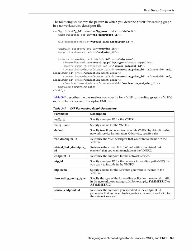
The following text shows the pattern in which you describe a VNF forwarding graph in a network service descriptor file:
<vnffg id="vnffg_id" name="vnffg_name" default="default"> <vnfd-reference ref-id="vnf_descriptor_id"/>
<vld-reference ref-id="virtual_link_descriptor_id"/>
<endpoint-reference ref-id="endpoint_id"/> <endpoint-reference ref-id="endpoint_id"/>
<network-forwarding-path id="nfp_id" name="nfp_name"> <forwarding-policy>forwarding_policy_type</forwarding-policy> <source-endpoint-reference ref-id="source_endpoint_id"/> <connection-point-reference ref-id="connection_point_id" vnfd-ref-id="vnf_descriptor_id" order="connection_point_order"/> <connection-point-reference ref-id="connection_point_id" vnfd-ref-id="vnf_descriptor_id" order="connection_point_order"/> <destination-endpoint-reference ref-id="destination_endpoint_id"/> </network-forwarding-path></vnffg>
Table 3–7 describes the parameters you specify for a VNF forwarding graph (VNFFG) in the network service descriptor XML file.
Table 3–7 VNF Forwarding Graph Parameters
Parameter Description
vnffg_id Specify a unique ID for the VNFFG.
vnffg_name Specify a name for the VNFFG.
default Specify true if you want to create this VNFFG by default during network service instantiation. Otherwise, specify false.
vnf_descriptor_id Reference the VNF descriptor that you want to include in the VNFFG.
virtual_link_descriptor_id
Reference the virtual link (defined within the virtual link element) that you want to include in the VNFFG.
endpoint_id Reference the endpoint for the network service.
nfp_id Specify a unique ID for the network forwarding path (NFP) that you want to include in the VNFFG.
nfp_name Specify a name for the NFP that you want to include in the VNFFG.
forwarding_policy_type Specify the type of the forwarding policy for the network traffic in the network forwarding path. For example, SYMMETRIC or ASYMMETRIC.
source_endpoint_id Reference the endpoint you specified in the endpoint_id parameter that you want to designate as the source endpoint for the network service.

About Design Components
3-10 Network Service Orchestration Implementation Guide
The following text shows a VNFFG element in the NPaaS.xml sample network service descriptor file:
<vnffg id="data-vnffg1" name="data-vnffg1" default="true"> <vnfd-reference ref-id="Juniper_vSRX"/>
<vld-reference ref-id="Data"/>
<endpoint-reference ref-id="Service_EP1"/> <endpoint-reference ref-id="Service_EP2"/>
<!-- Multiple network forwarding paths are supported. --> <network-forwarding-path id="nfp1" name="nfp1"> <forwarding-policy>SYMMETRIC</forwarding-policy> <source-endpoint-reference ref-id="Service_EP1"/> <connection-point-reference ref-id="CP01" vnfd-ref-id="VNFD1" order="1"/> <connection-point-reference ref-id="CP02" vnfd-ref-id="VNFD1" order="2"/> <destination-endpoint-reference ref-id="Service_EP2"/> </network-forwarding-path>
connection_point_id Reference the VNF connection point that you want to include in the NFP.
Typically, in a VNF, one connection point is connected to the DATA_IN network and another connection point is connected to the DATA_OUT network. In situations where a single connection point is connected to both DATA_IN and DATA_OUT networks, you must specify the VNF connection point twice, which indicates that the same connection point is used for both incoming and outgoing network traffic.
In the following example, the connection point CP11 is specified twice, which indicates that CP11 is connected to both DATA_IN and DATA_OUT networks:
<network-forwarding-path id="nfp1" name="nfp1"> <forwarding-policy>SYMMETRIC</forwarding-policy> <source-endpoint-reference ref-id="CP01"/> <connection-point-reference ref-id="CP11" vnfd-ref-id="VNFD1" order="1"/> <connection-point-reference ref-id="CP11" vnfd-ref-id="VNFD1" order="2"/> <connection-point-reference ref-id="CP21" vnfd-ref-id="VNFD2" order="3"/> <connection-point-reference ref-id="CP24" vnfd-ref-id="VNFD2" order="4"/> <connection-point-reference ref-id="CP31" vnfd-ref-id="VNFD3" order="5"/> <connection-point-reference ref-id="CP32" vnfd-ref-id="VNFD3" order="6"/> <destination-endpoint-reference ref-id="CP41"/></network-forwarding-path>
vnf_descriptor_id Reference the VNF descriptor that contains the connection point you specified in the connection_point_id parameter.
connection_point_order Specify the order of the connection point for the NFP.
destination_endpoint_id Reference the endpoint you specified in the endpoint_id parameter that you want to designate as the destination endpoint for the network service.
Table 3–7 (Cont.) VNF Forwarding Graph Parameters
Parameter Description

About Design Components
Designing and Onboarding Network Services, VNFs, and PNFs 3-11
</vnffg>
About VNF Descriptor FilesVNF descriptor files describe the deployment requirements, operational behavior, and policies required by VNFs that are based on them.
Network Service Orchestration includes the following sample VNF descriptor files:
■ Juniper_vSRX.xml. This is the descriptor file for the Juniper vSRX firewall VNF.
■ Checkpoint_NG_FW.xml. This is the descriptor file for the Checkpoint NG firewall VNF.
■ OracleComms_SBC.xml. This is the descriptor file for the Session Border Controller (SBC) VNF.
You use virtual network function descriptor file to do the following:
■ Describe the VNF descriptor information. See "Describing VNF Descriptor Information" for more information.
■ Describe the connection points for the VNF. See "Describing VNF Connection Points" for more information.
■ Describe the internal virtual links for the internal connection points of the Virtual Network Function Components (VNFCs). See "Describing Internal Virtual Links" for more information.
■ Describe the Virtual Deployment Unit (VDU) flavors. See "Describing Virtual Deployment Unit Flavors" for more information.
■ Describe the VDU images. See "Describing VDU Images" for more information.
■ Describe the VDUs on which you want to install the VNFCs. See "Describing Virtual Deployment Units" for more information.
■ Describe the VNF deployment flavors. See "Describing VNF Deployment Flavors" for more information.
Describing VNF Descriptor InformationIn the VNF descriptor file, you provide the VNF descriptor information, such as descriptor ID, descriptor name, vendor name, VNF descriptor version, and VNF version.
The following text shows the elements that enable you to provide information about the VNF descriptor XML file:
<nsd id="network_service_descriptor_id" name="network_service_descriptor_name"><vendor>vendor_name</vendor><version>descriptor_version</version><vnf-version>vnf_version</vnf-version>
Table 3–1 describes the parameters you specify to provide information about the VNF descriptor XML file.
Table 3–8 VNF Descriptor Information Parameters
Parameter Description
vnf_descriptor_id Specify a unique ID for the VNF descriptor that you want to include in the network service.
vnf_descriptor_name Specify a name for the VNF descriptor that you want to include in the network service.

About Design Components
3-12 Network Service Orchestration Implementation Guide
The following text shows the elements that provide descriptor information in the Juniper_vSRX.xml sample VNF descriptor file:
<vnfd id="Juniper_vSRX" name="Juniper_vSRX"><vendor>Oracle</vendor><version>1.0</version><vnf-version>1.0</vnf-version>
Describing VNF Connection PointsIn the VNF descriptor file, you can specify the internal, external, and management connection points for the VNF.
The following text shows the pattern in which you describe the internal, external, and management connection points in a VNF descriptor file.
<connection-point id="connection_point_id" name="connection_point_name" type="connection_point_type"/>
Table 3–9 describes the parameters you specify for internal and external connection points in the VNF descriptor XML file.
The following text shows a connection point element in the Juniper_vSRX.xml sample VNF descriptor file:
<!-- Multiple connection points are supported. --><connection-point id="CP03" name="CP03" type="MANAGEMENT"/><connection-point id="CP01" name="CP01" type="EXTERNAL"/><connection-point id="CP02" name="CP02" type="EXTERNAL"/>
Describing Internal Virtual LinksIn the VNF descriptor file, you can define the connectivity between the components within a VNF as internal virtual links. For each internal virtual link, specify the internal connection points that connect the internal virtual link to different components within a VNF.
vendor_name Specify the name of the VNF vendor.
descriptor_version Specify the version of the VNF descriptor.
vnf_version Specify the software version number for the VNF image.
Table 3–9 Connection Point Parameters
Parameter Description
connection_point_id Specify a unique ID for the VNF connection point.
connection_point_name Specify a name for the VNF connection point.
connection_point_type Specify the type of the VNF connection point. For example, MANAGEMENT, EXTERNAL, or INTERNAL.
Note: Network Service Orchestration does not use the VNF’s internal virtual link information; instead, it passes this information to the VNF manager for processing.
Table 3–8 (Cont.) VNF Descriptor Information Parameters
Parameter Description

About Design Components
Designing and Onboarding Network Services, VNFs, and PNFs 3-13
The following text shows the pattern in which you describe the internal virtual links in a VNF descriptor file.
<virtual-link id="virtual_link_id" name="virtual_link_name"> <connection-point-reference ref-id="connection_point_id"/> <connection-point-reference ref-id="connection_point_id"> <security enabled="security_value"> <extension type="extension_type" handler="extension_handler"> <parameter name="parameter_name" value="parameter_value" /> <parameter name="parameter_name" value="parameter_value" /></extension> </security></virtual-link>
Table 3–10 describes the parameters you specify for internal virtual links in the VNF descriptor XML file.
The following text shows a virtual link element that you specify for an internal virtual link of a VNF in a sample VNF descriptor file:
<!-- Multiple Internal Virtual Links are supported. --><!-- Specifying Internal Virtual Links is Optional --><virtual-link id="InternalVL" name="InternalVL"> <connection-point-reference ref-id="CP04"/> <connection-point-reference ref-id="CP05"/> <security enabled="true"> <extension type="SecurityGroups" handler="com.oracle.impl.ExtnImpl"> <!-- Multiple security groups are supported. --> <parameter name="security_groups" value="open, default"/> </security></virtual-link>
Describing Virtual Deployment Unit FlavorsIn the VNF descriptor file, you can define VDU deployment flavors that represent specific deployment of a VDU supporting specific key performance indicators (KPIs), such as compute, memory, and storage capacity.
The following text shows the pattern in which you describe the VDU flavor in a VNF descriptor file.
<vdu-flavor id="vdu_flavor_id" name="vdu_flavor_name">
Table 3–10 Internal Virtual Link Parameters
Parameter Description
virtual_link_id Specify a unique ID for the internal virtual link.
virtual_link_name Specify a name for the virtual link.
connection_point_id Reference the internal connection point of the VNF.
security_value Specify whether internal virtual links should be created with security enabled or disabled. Specify true to enable security for the internal virtual links. Otherwise, specify false.
extension_type Specify the type of the extension.
extension_handler Specify the fully qualified class name of the handler implementation class.
parameter_name The name of the parameter for the extension.
parameter_value The value of the parameter for the extension.

About Design Components
3-14 Network Service Orchestration Implementation Guide
<cpu>cpu</cpu> <memory>memory</memory> <storage>disk_space</storage></vdu-flavor>
Table 3–11 describes the parameters you specify for a VDU flavor in the VNF descriptor XML file.
The following text shows a vdu-flavor element in the Juniper_vSRX.xml sample VNF descriptor file:
<vdu-flavor id="vsrx.small" name="vsrx.small"> <cpu>2</cpu> <memory>2GB</memory> <storage>20GB</storage></vdu-flavor><vdu-flavor id="vsrx.medium" name="vsrx.medium"> <cpu>2</cpu> <memory>4GB</memory> <storage>20GB</storage></vdu-flavor><vdu-flavor id="m1.medium" name="m1.medium"> <cpu>2</cpu> <memory>4GB</memory> <storage>40GB</storage></vdu-flavor>
Describing VDU ImagesIn the VNF descriptor file, you can specify the VDU images that you want to instantiate for a VNF.
The following text shows the pattern in which you describe the VDU images in a VNF descriptor file.
<image id="image_id"> <software-image name="image_name" version="image_version"> <extension type="extension_type" handler="extension_handler"> <parameter name="parameter_name" value="parameter_value"/> <parameter name="parameter_name" value="parameter_value"/> </extension> </software-image></image>
Table 3–13 describes the parameters you specify for a VDU image in the VNF descriptor XML file.
Table 3–11 Virtual Deployment Unit Flavor Parameters
Parameter Description
vdu_flavor_id Specify a unique ID for the VDU flavor.
vdu_flavor_name Specify a name for the VDU flavor.
cpu Specify the number of virtual CPUs that you want to allocate for the VDU.
memory Specify the memory you want to allocate for the VDU. Specify the memory in GB.
disk_space Specify the disk space that you want to allocate for the VDU. Specify the disk space in GB.

About Design Components
Designing and Onboarding Network Services, VNFs, and PNFs 3-15
The following text shows an image element in the Juniper_vSRX.xml sample VNF descriptor file:
<image id="vsrx-v1.0" > <software-image name="vsrx-12.1X47-D20.7-npaas-v0.3" version="1.0" > <extension type="ImageCredentials" handler="oracle.communications.inventory.nso.extensions.impl.ImageCredentialsHandlerImpl"> <parameter name="username" value="root" /> <parameter name="password" value="labms01" /> </extension> </software-image> </image>
Describing Virtual Deployment UnitsIn the VNF descriptor file, you can describe Virtual Deployment Units, which represent the virtual machines on which VNF components (VNFCs) can be deployed.
The following text shows the pattern in which you describe the rules in a VNF descriptor file.
<vdu id="vdu_id" name="vdu_name"> <image-reference ref-id="image_id"/> <vnfc id="vnfc_id" name="vnfc_name"> <connection-point-reference ref-id="connection_point_id" order="connection_point_order"/> <connection-point-reference ref-id="connection_point_id" order="connection_point_order"> <connection-point-reference ref-id="connection_point_id" order="connection_point_order"> </vnfc> <security enabled="security_value"> <!-- Security group values can be provided dynamically during instantiation --> <extension type="extension_type" handler="extension_handler"> <!-- Multiple security groups are supported. --> <parameter name="parameter_name" value="parameter_value"> <parameter name="parameter_name" value="parameter_value"> </extension> </security></vdu>
Table 3–13 describes the parameters you specify for a VDU in the VNF descriptor XML file.
Table 3–12 VNF Image Parameters
Parameter Description
image_id Specify a unique ID for the VDU image.
image_name Specify a name for the VDU image.
image_version Specify the software version number for the VDU image.
extension_type Specify the type of the extension.
extension_handler (Optional) Specify the handler for the extension.
parameter_name The name of the parameter for the extension.
parameter_value The value of the parameter for the extension.

About Design Components
3-16 Network Service Orchestration Implementation Guide
The following text shows a vdu element in the Juniper_vSRX.xml sample VNF descriptor file:
<!-- Multiple VDUs are supported. --><vdu id="Juniper_vSRX_VDU" name="Juniper_vSRX_VDU"> <image-reference ref-id="vsrx-v1.0"/> <vnfc id="vsrxc" name="vsrxc"> <connection-point-reference ref-id="CP03" order="1"/> <!-- Management port will not have VL reference --> <connection-point-reference ref-id="CP01" order="2"/> <!-- External CP does not have VL reference --> <connection-point-reference ref-id="CP01" order="3"/> <!-- External CP does not have VL reference --> </vnfc> <security enabled="true"> <!-- Security group values can be provided dynamically during instantiation --> <!-- If no handler is provided, Network Service Orchestration will use its default SecurityGroupHandler. --> <!-- Otherwise provide the fully qualified class name of the handler implementation class. e.g., handler="com.oracle.impl.SecurityGroupHandlerImpl" --> <extension type="SecurityGroups"> <!-- Multiple security groups are supported. --> <parameter name="type" type="VDU"> <parameter name="security_groups" type="open, default"> </extension> <extension type="SecurityGroups"> <!-- Multiple security groups are supported. --> <parameter name="type" type="CP"> <parameter name="security_groups" type="all"> <parameter name="connection_points" type="CP01, CP02"> </extension> </extensions> </security></vdu>
Table 3–13 Virtual Deployment Unit Parameters
Parameter Description
vdu_id Specify a unique ID for the VDU.
vdu_name Specify a name for the VDU.
image_id Reference the VDU image that should be used to instantiate the VDU.
vnfc_id Specify a unique ID for the VNF component in the VDU.
vnfc_name Specify a name for the VNF component in the VDU.
connection_point_id Reference a VNF connection point.
connection_point_order Specify the order of the connection point.
security_value Specify whether the VDU should be created with security enabled or disabled. Specify true to enable security; otherwise, specify false.
extension_type Specify the type of the extension.
extension_handler (Optional) Specify the fully qualified class name of the handler implementation class.
parameter_name The name of the parameter for the extension.
parameter_value The value of the parameter for the extension.
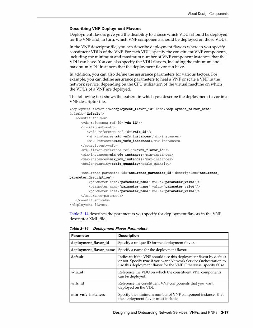
About Design Components
Designing and Onboarding Network Services, VNFs, and PNFs 3-17
Describing VNF Deployment FlavorsDeployment flavors give you the flexibility to choose which VDUs should be deployed for the VNF and, in turn, which VNF components should be deployed on those VDUs.
In the VNF descriptor file, you can describe deployment flavors where in you specify constituent VDUs of the VNF. For each VDU, specify the constituent VNF components, including the minimum and maximum number of VNF component instances that the VDU can have. You can also specify the VDU flavors, including the minimum and maximum VDU instances that the deployment flavor can have.
In addition, you can also define the assurance parameters for various factors. For example, you can define assurance parameters to heal a VNF or scale a VNF in the network service, depending on the CPU utilization of the virtual machine on which the VDUs of a VNF are deployed.
The following text shows the pattern in which you describe the deployment flavor in a VNF descriptor file.
<deployment-flavor id="deployment_flavor_id" name="deployment_falvor_name" default="default"> <constituent-vdu> <vdu-reference ref-id="vdu_id"/> <constituent-vnfc> <vnfc-reference ref-id="vnfc_id"/> <min-instances>min_vnfc_instances</min-instances> <max-instances>max_vnfc_instances</max-instances> </constituent-vnfc> <vdu-flavor-reference ref-id="vdu_flavor_id"/> <min-instances>min_vdu_instances</min-instances> <max-instances>max_vdu_instances</max-instances> <scale-quantity>scale_quantity</scale_quantity>
<assurance-parameter id="assurance_parameter_id" description="assurance_parameter_description"> <parameter name="parameter_name" value="parameter_value"/> <parameter name="parameter_name" value="parameter_value"/> <parameter name="parameter_name" value="parameter_value"/> </assurance-parameter> </constituent-vdu></deployment-flavor>
Table 3–14 describes the parameters you specify for deployment flavors in the VNF descriptor XML file.
Table 3–14 Deployment Flavor Parameters
Parameter Description
deployment_flavor_id Specify a unique ID for the deployment flavor.
deployment_flavor_name Specify a name for the deployment flavor.
default Indicates if the VNF should use this deployment flavor by default or not. Specify true if you want Network Service Orchestration to use this deployment flavor for the VNF. Otherwise, specify false.
vdu_id Reference the VDU on which the constituent VNF components can be deployed.
vnfc_id Reference the constituent VNF components that you want deployed on the VDU.
min_vnfc_instances Specify the minimum number of VNF component instances that the deployment flavor must include.

About Design Components
3-18 Network Service Orchestration Implementation Guide
The following text shows the deployment flavor element in the Juniper_vSRX.xml sample VNF descriptor file:
<!-- Multiple deployment flavors are supported. --><deployment-flavor id="standard" name="standard" default="true"><!-- Each deployment flavor can further choose which VDU, and which VNFC in the VDU to deploy. --><!-- For example: depFlavor1 only selects VDUTypeA, VNFCTypeX to deploy, but not VNFCTypeY. -->
<constituent-vdu> <vdu-reference ref-id="Juniper_vSRX_VDU"/> <constituent-vnfc> <vnfc-reference ref-id="vsrxc"/> <min-instances>1</min-instances> <max-instances>1</max-instances> </constituent-vnfc> <vdu-flavor-reference ref-id="vsrxc"/> <min-instances>1</min-instances> <max-instances>1</max-instances> <scale-quantity>2</scale-quantity>
<assurance-parameter id="ap1" description="Low CPU Utilization"> <parameter name="meter_name" value="cpu_util"/> <parameter name="value" value="0.0"/> <parameter name="condition" value="eq"/> <parameter name="action" value="heal"/> </assurance-parameter>
<assurance-parameter id="ap2" description="High CPU Utilization"> <parameter name="meter_name" value="cpu_util"/> <parameter name="value" value="80.0"/> <parameter name="condition" value="gt"/> <parameter name="action" value="scale"/> </assurance-parameter>
max_vnfc_instances Specify the maximum number of VNF component instances that the deployment flavor can include.
vdu_flavor_id Reference the VDU flavor ID.
min_vdu_instances Specify the minimum number of VDU instances that the deployment flavor must include.
max_vdu_instances Specify the maximum number of VDU instances that the deployment flavor can include.
scale_quantity Specify the number of VDU instances that should be added when you scale-out a VNF. Similarly, this parameter determines the number of VDU instances that should be removed when you scale-in a VNF.
assurance_parameter_id Specify a unique ID for the assurance parameter.
assurance_parameter_description
Provide a description to identify the purpose of the assurance parameter. For example, specify Low CPU Utilization or High CPU Utilization.
parameter_name Specify the parameter name for the assurance parameter.
parameter_value Specify the parameter value for the assurance parameter.
Table 3–14 (Cont.) Deployment Flavor Parameters
Parameter Description

About Design Components
Designing and Onboarding Network Services, VNFs, and PNFs 3-19
</constituent-vdu></deployment-flavor>
About PNF Descriptor FilesPNF descriptor files describe the deployment requirements, operational behavior, and policies required by PNFs that are based on them.
In the PNF descriptor file, you specify:
■ Vendor details
■ The version of the PNF descriptor
■ The software version of the PNF
■ Connection points for the PNF
The following text shows the pattern in which you describe a PNF in the PNF descriptor file:
<pnfd id="pnf_descriptor_id" name="pnf_descriptor_name">
<vendor>vendor_name</vendor> <version>descriptor_version</version> <pnf-version>pnf_version</pnf-version>
<!-- Multiple connection points are supported. --> <connection-point id="connection_point_id" name="connection_point_name"/> <connection-point id="connection_point_id" name="connection_point_name"/> <connection-point id="connection_point_id" name="connection_point_name"/>
</pnfd>
Table 3–15 describes the parameters you specify to provide information about the PNF descriptor XML file.
Network Service Orchestration includes the following sample PNF descriptor file:
■ Cisco_xRV.xml. This descriptor file can be used for the Cisco xRV router PNF.
The following text shows the elements in the Cisco_xRV.xml sample PNF descriptor file:
<pnfd id="Cisco_xRV" name="Cisco_xRV">
Table 3–15 PNF Descriptor Parameters
Parameter Description
pnf_descriptor_id Specify a unique ID for the PNF descriptor that you want to include in the network service.
pnf_descriptor_name Specify a name for the PNF descriptor that you want to include in the network service.
vendor_name Specify the name of the PNF vendor.
descriptor_version Specify the version of the PNF descriptor.
pnf_version Specify the software version number for the PNF image.
connection_point_id Specify a unique ID for the PNF connection point.
connection_point_name Specify a name for the PNF connection point.

About Design Components
3-20 Network Service Orchestration Implementation Guide
<vendor>CISCO</vendor> <version>1.0</version> <pnf-version>1.0</pnf-version>
<!-- Multiple connection points are supported. --> <connection-point id="CP01" name="CP01"/> <connection-point id="CP02" name="CP02"/> <connection-point id="CP03" name="CP03"/>
</pnfd>
Creating a Descriptor FileIn Design Studio, you create a descriptor file for each Network Service specification and VNF Service specification.
To create a descriptor file:
1. In Design Studio, import all the Network Service Orchestration cartridges. See "Setting Up Design Studio for Extending Network Service Orchestration" for more information about importing the cartridges into Design Studio.
2. Switch to the Navigator view.
3. In the root directory of the cartridge project, create the following folder structure:
model/content/product_home/config
4. Right-click on the config folder and create an XML file with the name ServiceSpecificationName.xml for a network service, LogicalDeviceSpecificationName.xml for a VNF, and LogicalDeviceSpecificationName.xml for a PNF.
where:
■ ServiceSpecificationName is the name of the service specification
■ LogicalDeviceSpecificationName is the name of the logical device specification, which represents a VNF or a PNF.
5. Copy the sample content from the sample cartridge project to the XML file and modify it according to your service requirements.
About Technical Actions FilesTechnical actions files describe the actions for the VNFs, PNFs, and network services in a VIM. There is one technical actions file for each network service, VNF, and PNF.
In the technical actions file, for each technical action, you define the following elements:
■ action: This element declares a technical action, its signature (which contains the name and type of each parameter), and the type of its subject and target.
■ match: This element declares configuration differences that match an XPath expression.
■ generator: This element defines all the bindings of the configuration to the parameters, subject, and target of the action to be generated.
The following example shows the elements in the Juniper_vSRX_Service_TechnicalActions.xml file:
<technicalActionCalculator xmlns="http://xmlns.oracle.com/communications/inventory/actioncalculator"

About Design Components
Designing and Onboarding Network Services, VNFs, and PNFs 3-21
xmlns:invactcalc="http://xmlns.oracle.com/communications/inventory/actioncalculator" xmlns:xsi="http://www.w3.org/2001/XMLSchema-instance" xsi:schemaLocation="http://xmlns.oracle.com/communications/inventory/actioncalculator ../../../../../../calc_tech_actions_uim_workspace/ora_uim_calculate_technical_order_metadata/schemas/TechnicalActionCalculator.xsd"> <invactcalc:action> <name>DEPLOY_VNF</name> <actionCode>DEPLOY_VNF</actionCode> <subject> <class>LogicalDevice</class> </subject> <target> <class>LogicalDevice</class> </target> <parameter> <name>serviceID</name> <type>string</type> </parameter> <parameter> <name>vnfID</name> <type>string</type> </parameter> <parameter> <name>vnfName</name> <type>string</type> </parameter> <parameter> <name>vnfdName</name> <type>string</type> </parameter> <parameter> <name>flavor</name> <type>string</type> </parameter> <parameter> <name>vimId</name> <type>string</type> </parameter> <parameter> <name>vdus</name> <type>string</type> </parameter> <parameter> <name>vnfcs</name> <type>string</type> </parameter> <parameter> <name>ports</name> <type>string</type> </parameter> </invactcalc:action> <invactcalc:match> <invactcalc:diff> <invactcalc:path>/root/after/vnf/Assignment[@State='PENDING_ASSIGN'

About Design Components
3-22 Network Service Orchestration Implementation Guide
and /root/service[state!='PENDING_DISCONNECT']]/..</invactcalc:path> </invactcalc:diff> <invactcalc:action>DEPLOY_VNF</invactcalc:action> <invactcalc:anchor>.</invactcalc:anchor> </invactcalc:match> <invactcalc:generator> <invactcalc:action>DEPLOY_VNF</invactcalc:action> <invactcalc:condition>/root/after/vnf/Assignment[@State='PENDING_ASSIGN']</invactcalc:condition> <subject>.</subject> <target>.</target> <binding> <parameter>serviceID</parameter> <path>/root/service/id</path> </binding> <binding> <parameter>vnfID</parameter> <path>Assignment/id</path> </binding> <binding> <parameter>vnfName</parameter> <path>Assignment/name</path> </binding> <binding> <parameter>vnfdName</parameter> <path>Assignment/specification</path> </binding> <binding> <parameter>flavor</parameter> <path>Assignment/flavorName</path> </binding> <binding> <parameter>vimId</parameter> <path>Assignment/vimId</path> </binding> <binding> <parameter>vdus</parameter> <path>string-join(vdus/vdu/( concat( 'id:', @id, '_VDUAttrDlm_', 'name:', Assignment/name, '_VDUAttrDlm_', 'imageName:', Assignment/imageName, '_VDUAttrDlm_', 'imageId:', Assignment/imageId, '_VDUAttrDlm_', 'imageVersion:', Assignment/imageVersion, '_VDUAttrDlm_', 'availabilityZone:', Assignment/availabilityZoneName, '_VDUAttrDlm_', 'flavorName:', Assignment/flavorName, '_VDUAttrDlm_', 'securityGroups:', Assignment/securityGroups, '_VDUAttrDlm_' )), '_VDUDlm_') </path> </binding> <binding> <parameter>vnfcs</parameter> <path>string-join(vdus/vdu/vnfcs/vnfc/( concat( 'vduItemId:', ../../@id, '_VNFCAttrDlm_', 'id:', @id, '_VNFCAttrDlm_' )), '_VNFCDlm_') </path>

About Design Components
Designing and Onboarding Network Services, VNFs, and PNFs 3-23
</binding> <binding> <parameter>ports</parameter> <path>string-join(vdus/vdu/vnfcs/vnfc/connectionPoints/connectionPoint/( concat( 'vnfcItemId:', ../../@id, '_PortAttrDlm_', 'id:', port/Reference/id, '_PortAttrDlm_', 'cpName:',Reference/name, '_PortAttrDlm_', 'extNetId:', network/Reference/extNetId, '_PortAttrDlm_', 'extSubnetId:', network/Reference/externalID, '_PortAttrDlm_', 'isDhcpEnabled:', network/isDhcpEnabled, '_PortAttrDlm_', 'isPortSecurityEnabled:',isPortSecurityEnabled,'_PortAttrDlm_', 'securityGroups:',securityGroups, '_PortAttrDlm_', 'order:',order, '_PortAttrDlm_' )), '_PortDlm_') </path> </binding> </invactcalc:generator></technicalActionCalculator>
Creating a Technical Actions FileIn Design Studio, you create a technical actions file for each Network Service specification, a VNF Service specification, and a PNF specification.
To create a technical actions file:
1. In Design Studio, switch to the Navigator view.
2. In the root directory of the cartridge project, create the following folder structure:
model/content/product_home/config
3. Right-click on the config folder and create an XML file with the name ServiceSpecificationName_TechnicalActions.xml, where ServiceSpecificationName is the name of the service specification.
4. Copy the sample content from the sample cartridge project to the XML file and modify it according to your service requirements.
About VNF Configuration FilesDepending on the functionality that they deliver, some VNFs in a network service may require configuration after they are deployed. After a VNF is deployed, you can configure the VNF based on its configuration requirements.
To configure a VNF, Network Service Orchestration requires the following configuration files to be created:
■ VNFD_NameTemplate.conf
This is a VNF-specific configuration template in which you specify the placeholder fields for instance-specific parameters.
■ VNFD_NameConfig.xml
Note: Post-deployment configuration of VNFs is not always required.

Setting Network Service Descriptor Properties
3-24 Network Service Orchestration Implementation Guide
This is a configuration file in which you specify the VNF instance-specific configuration parameter values as name-value pairs.
Network Service Orchestration generates the VNFD_Name.conf configuration file based on the VNFD_NameTemplate.conf file and the VNFD_NameConfig.xml file.
Network Service Orchestration reads all the name-value pairs in the VNFD_NameConfig.xml file and replaces the placeholder fields in the VNFD_NameTemplate.conf file and generates the VNFD_Name.conf file.
The following text shows a sample configuration template for the Juniper vSRX VNF in the Juniper_vSRX_Template.conf configuration file:
<rpc> <edit-config> <target> <candidate/> </target> <config> <configuration> <security> <utm> <custom-objects> <url-pattern> <name>bad-sites</name> <value>{{site-name}}</value> </url-pattern> </custom-objects> </utm> </security> </configuration> </config> </edit-config> </rpc>
The following example shows a sample configuration for the Juniper vSRX VNF in the Juniper_vSRX_Config.xml configuration file:
<vnfConfiguration> <config> <param> <name>site-name</name> <value>www.example.com</value> </param> <sbiToPushConfiguration> <interface>netconf</interface> <interface-script></interface-script> </sbiToPushConfiguration> <action>null</action> </config> </vnfConfiguration>
Setting Network Service Descriptor PropertiesYou define and specify properties for your network service in the UIM_Home/config/network_service_descriptor.properties file, where network_service_descriptor is the name of your network service descriptor. You create one properties file for each network service that you want to create and implement.
Table 3–16 describes the parameters that you specify for a network service.

Setting Network Service Descriptor Properties
Designing and Onboarding Network Services, VNFs, and PNFs 3-25
Network Service Orchestration provides properties files for the following sample network services:
■ UIM_Home/config/NPaas.properties. This properties file defines the properties for the NPaaS sample network service.
Table 3–16 Network Service Descriptor Parameters
Parameter Description
network_service_descriptor.default.dataCenter
Used to specify the default data center if you use multiple VIMs. Otherwise, leave blank.
network_service_descriptor indicates the name of the network service descriptor. For example, NPaaS.
VIM_Id.network_service_descriptor.VLD_Name
Used to specify the name of the management network. In the properties files of the samples, by default, the VIM ID is OpenStack. The management network is the VLD Name that is specified in the NPaaS.xml file.
If you use multiple VIMs, add another entry of the same parameter and specify the VIM ID and the management network.
Add multiple instances of this parameter for specifying more VLDs.
VIM_Id.network_service_descriptor.Data_IN
Used to specify the VIM ID and the name of the data-in network. By default, the VIM ID is OpenStack.
If you use multiple VIMs, add another entry of the same parameter and specify the VIM ID and the data-in network.
VIM_Id.network_service_descriptor.Data_OUT
Used to specify the VIM ID and the name of the data-out network. By default, the VIM ID is OpenStack.
If you use multiple VIMs, add another entry of the same parameter and specify the VIM ID and the data-out network.
(Optional) sdnController.network_service_descriptor
Used to specify an implementation class for the SDN controller interface. The default implementation class is com.oracle.communications.inventory.nso.nfvi.sdn.ODLManager.
(Optional) network_service.ovs.pktInToOVSPort
Used to specify the Open vSwitch port number of the packet-in network.
(Optional) network_service.ovs.pktOutToOVSPort
Used to specify the Open vSwitch port number of the packet-out network.
(Optional) network_service.ovs.custNetToOVSPort
Used to specify the Open vSwitch port number of the customer-side network.
(Optional) network_service.ovs.internetToOVSPort
Used to specify the Open vSwitch port number of the internet-side network.
(Optional) npaas.ovs.bridge_id Specify the bridge ID for the Open VSwitch and prefix it with openflow. For example, openflow:OpenFlow_ID, where OpenFlow_ID is the OpenFlow ID.
To retrieve the OpenFlow ID, in OpenDaylight call the following OpenDaylight REST API:
http://odlIPaddress:port/restconf/operational/opendaylight-inventory:nodes/
where odlIPaddress is the IP address and port is the port number of the OpenDaylight virtual machine.

Onboarding Network Services and VNFs Using TOSCA Descriptor Templates
3-26 Network Service Orchestration Implementation Guide
■ UIM_Home/config/ResidentialGateway.properties. This properties file defines the properties for the Residential Gateway sample network service.
■ The following properties files define the properties for the Proxy-Call Session Control Function (P-CSCF) network service.
– UIM_Home/config/aoconfig.properties
– UIM_Home/config/P-CSCF.properties
Onboarding Network Services and VNFs Using TOSCA Descriptor Templates
Topology and Orchestration Specification for Cloud Applications (TOSCA) is an OASIS standard language to describe the topology of cloud-based services. TOSCA provides specifications for defining NFV descriptors. Network Service Orchestration supports tosca_simple_profile_for_nfv_1_0_0 and OpenStack Tacker NFV Profiles for NFV properties.
For more information about TOSCA, see the standards section on the OASIS web site: https://www.oasis-open.org/standards#toscav1.0
Network Service Orchestration supports onboarding of network services and VNFs using TOSCA descriptor templates that are in YAML format. Network Service Orchestration requires OpenStack TOSCA parser 6.0 (or later) to parse the descriptors.
To onboard Network Services and VNFs you import the TOSCA descriptor templates into Design Studio. When you import a TOSCA descriptor template, Network Service Orchestration processes the YAML file that contains the structural and topology details (connection points and connectivity requirements) and creates a network service cartridge project or a VNF cartridge project with the required UIM entity specifications (such as Logical Device, Service, and Service Configuration specifications), assigned or referenced resource specifications, and characteristic specifications.
Before you import the TOSCA descriptor templates into Design Studio, do the following:
1. Install Python 3.5.2. See "Installing Python" for instructions.
2. Create a new environment variable PYTHON_EXECUTABLE and add the full path to the python executable file. For example, C:\Program Files\Python35\python.exe.
3. Download the UIM_SDK.zip file and extract its contents.
4. The UIM_SDK\NSO tools\ToscaTranslator\ directory contains the following files:
■ OracleCommsToscaTranslator.zip
■ OracleCommsToscaTranslatorEnvSetup.zip
5. In the TOSCA_TRANSLATOR_HOME environment variable, add the path to the directory in which you extracted the OracleCommsToscaTranslator.zip file. For example, UIM_SDK\NSO tools\ToscaTranslator. The OracleCommsToscaTranslator.zip contains the lib directory and the OracleCommsToscaTranslator.pyz file.

Onboarding Network Services and VNFs Using TOSCA Descriptor Templates
Designing and Onboarding Network Services, VNFs, and PNFs 3-27
6. If your Design Studio workspace is already open, close and reopen the workspace.
7. Import the required UIM base cartridges into Design Studio.
See "Setting Up Design Studio for Extending Network Service Orchestration" for information about the required UIM base cartridges.
Sample TOSCA VNF Descriptor TemplateThe following text shows the TOSCA VNF descriptor template in YAML format for the sample Juniper_vSRX.yaml file. This sample shows the supported properties.
tosca_definitions_version: tosca_simple_profile_for_nfv_1_0_0 description: juniper vSRX firewall metadata: template_name: Juniper_vSRX_tosca template_type: VNF ID: Juniper_vSRX_tosca vendor: Juniper version: 1.0 topology_template: node_templates: Juniper_vSRX_VDU: type: tosca.nodes.nfv.VDU.Tacker capabilities: nfv_compute: properties: num_cpus: 2 mem_size: 4GB disk_size: 20GB properties: image: vsrx-12.1X47-D20.7-npaas-v0.3 CP03: type: tosca.nodes.nfv.CP.Tacker properties: management: true order: 0 requirements: - virtualBinding: node: Juniper_vSRX_VDUCP01: type: tosca.nodes.nfv.CP.Tacker properties: order: 2 requirements: - virtualBinding:
Note: If your operating system does not consider an environment variable defined with a blank space in the directory names, you can extract the OracleCommsToscaTranslator.zip file and move its contents to any location, and then provide the path of this location in the TOSCA_TRANSLATOR_HOME environment variable. Ensure that the lib directory and the OracleCommsToscaTranslator.pyz file are located in the same directory.

Onboarding Network Services and VNFs Using TOSCA Descriptor Templates
3-28 Network Service Orchestration Implementation Guide
node: Juniper_vSRX_VDU policies: - ScalingPolicy: type: tosca.policies.tacker.Scaling properties: increment: 1 min_instances: 1 max_instances: 3 default_instances: 1 targets: [Juniper_vSRX_VDU] - vdu1_cpu_usage_monitoring_policy: type: tosca.policies.tacker.Alarming triggers: resize_compute: event_type: type: tosca.events.resource.utilization implementation: ceilometer metrics: cpu_util condition: threshold: 50 constraint: utilization greater_than 50% period: 600 evaluations: 1 method: avg comparison_operator: gt action: resize_compute: action_name: respawn targets: [Juniper_vSRX_VDU]
Figure 3–1 depicts the TOSCA VNF Template to the VNF virtual machine mapping.
Figure 3–1 TOSCA VNF Template to VNF Virtual Machine Mapping
In the illustration, the Firewall_VNF VNF comprises one Virtual Deployment Unit (VDU) that is connected to three virtual links. The VDU has three connection points: CP1 (connection point 1) is connected to Mgmt-net (management network), CP2 (connection point 2) is connected to Pkt-in (packet-in network), and CP3 (connection

Onboarding Network Services and VNFs Using TOSCA Descriptor Templates
Designing and Onboarding Network Services, VNFs, and PNFs 3-29
point 3) is connected to Pkt-out (packet-out network). The networks are defined in the network service descriptor.
Sample TOSCA Network Service Descriptor TemplateThe following text shows the TOSCA network service descriptor template in YAML format for the sample NPaaS.yaml file. This sample shows the supported properties.
tosca_definitions_version: tosca_simple_profile_for_nfv_1_0_0 description: NPaaS Network Service description: NPaaS Network Servicemetadata: template_name: NPaaS_tosca template_type: NS ID: NPaaS_tosca vendor: Oracle version: 1.0imports: - juniper_vSRX_definition.yaml - Juniper_vSRX.yaml topology_template: node_templates: Juniper_vSRX_tosca: type: tosca.nodes.nfv.VNF.Juniper requirements: - virtualLink1: data - virtualLink2: mgmt data: type: tosca.nodes.nfv.VL properties: network_name: data vendor: Oracle mgmt: type: tosca.nodes.nfv.VL properties: network_name: mgmt vendor: Oracle policies: - ScalingPolicy: type: tosca.policies.tacker.Scaling properties: increment: 1 min_instances: 1 max_instances: 3 default_instances: 1 targets: [Juniper_vSRX_tosca]
To make the VNFs a part of the network service, do the following:
■ Define the substitution_mappings in each VNF YAML file, as follows:
topology_template: substitution_mappings: node_type:

Onboarding Network Services and VNFs Using TOSCA Descriptor Templates
3-30 Network Service Orchestration Implementation Guide
requirements: virtualLink1: virtualLink2: node_templates:
The following example shows the substitution mappings that you must define when you import the Juniper_vSRX.yaml file into the NPaas.yaml file:
tosca_definitions_version: tosca_simple_profile_for_nfv_1_0_0 description: juniper vSRX firewall imports: - <Full directory Path of this file>\Juniper_vSRX_definition.yaml # Replace <Full directory Path of this file> with full path of directory containing Juniper_vSRX_definition.yaml file topology_template: substitution_mappings: node_type: tosca.nodes.nfv.VNF.Juniper requirements: virtualLink1: [CP01, CP02, virtualLink] virtualLink2: [CP03, virtualLink] node_templates: Juniper_vSRX_VDU: type: tosca.nodes.nfv.VDU.Tacker capabilities: nfv_compute: properties: num_cpus: 2 mem_size: 4GB disk_size: 20GB properties: image: vsrx-12.1X47-D20.7-npaas-v0.3 CP03: type: tosca.nodes.nfv.CP.Tacker properties: management: true order: 0 requirements: - virtualBinding: node: Juniper_vSRX_VDU CP02: type: tosca.nodes.nfv.CP.Tacker properties: order: 1 requirements: - virtualBinding: node: Juniper_vSRX_VDU CP01: type: tosca.nodes.nfv.CP.Tacker properties: order: 2 requirements: - virtualBinding: node: Juniper_vSRX_VDU

Onboarding Network Services and VNFs Using TOSCA Descriptor Templates
Designing and Onboarding Network Services, VNFs, and PNFs 3-31
■ For each node type representing a VNF node, you must define a corresponding definition file.
The following is the sample definition file for the node type tosca.nodes.nfv.VNF.Juniper.
tosca_definitions_version: tosca_simple_profile_for_nfv_1_0_0 node_types: tosca.nodes.nfv.VNF.Juniper: derived_from: tosca.nodes.nfv.VNF requirements: - virtualLink1: capability: tosca.capabilities.nfv.VirtualLinkable relationship: tosca.relationships.nfv.VirtualLinksTo node: tosca.nodes.nfv.VL - virtualLink2: capability: tosca.capabilities.nfv.VirtualLinkable relationship: tosca.relationships.nfv.VirtualLinksTo node: tosca.nodes.nfv.VL
The following are some points that you should keep in mind when importing the TOSCA descriptor files:
■ Network Service Orchestration supports multiple VNF components (VNFCs) within a single VDU; however, the TOSCA definitions support only VDUs. To define a TOSCA YAML descriptor for a VNF that has multiple VNFCs, you must define a separate VDU for each VNFC.
■ Under ScalingPolicy, the default_instances field maps to the <min_instances> element in the network service descriptor and the VNF descriptor.
■ Network Service Orchestration looks for the following fields under the metadata section in the TOSCA VNF descriptor and TOSCA Network Service descriptor templates:
– template_type: Specify VNF in the TOSCA VNF descriptor template and specify NS in the TOSCA Network Service descriptor template.
– ID: Specify an ID for the TOSCA VNF descriptor template and the TOSCA Network Service descriptor template.
Installing PythonTo install python:
1. Download and extract the UIM_SDK.zip file.
2. Navigate to the UIM_SDK\NSO tools\ToscaTranslator directory and extract the OracleCommsToscaTranslatorEnvSetup.zip file.
The extracted OracleCommsToscaTranslatorEnvSetup directory contains different directories for Windows and Linux operating systems.
3. Run the following command:
■ For Windows machine, launch command prompt and run the following command as administrator:
Note: Before you run the commands, ensure that you have a working internet connection.

Onboarding Network Services and VNFs Using TOSCA Descriptor Templates
3-32 Network Service Orchestration Implementation Guide
install.bat
If you use proxy and a target directory, run the following command:
install.bat -proxy="www-proxy.example.com:port" -targetdir="C:\python35"
where:
– www-proxy.example.com:port is the proxy
– C:\python35 is the target directory of Python
See Table 3–17 for details about the command line argument options.
■ For Linux machine, from terminal, run the following command as a pseudo user or with root permission:
install.sh
The installation script installs python and the required libraries on the machine.
Table 3–17 describes the command line arguments.
Importing the TOSCA VNFD Template into Design StudioTo import the TOSCA VNF template into Design Studio:
1. In Design Studio, from the Studio menu, select Show Design Perspective.
2. Click the Studio Projects tab.
The Studio Projects view appears.
3. Right-click in the Studio Projects view, select Import, and then select Import VNFD TOSCA Template.
The Import VNFD TOSCA Template dialog box appears.
4. Click Browse and select the TOSCA VNF descriptor file or the TOSCA network service descriptor file in YAML format.
Design Studio creates the VNF cartridge project or the network service cartridge project with the required specifications.
After the VNF cartridge project is generated, to use this cartridge with a network service, make appropriate changes in your network service cartridge project. For more information about working with network service cartridges, see "Designing Custom Network Services".
After the network service cartridge project is generated, before you deploy the network service, you must import or create any dependent VNF cartridge projects, and then make appropriate changes in your network service cartridge project. For more information about working with network service cartridges, see "Designing Custom Network Services".
Table 3–17 Command Line Arguments
For Windows For Linux Usage
-proxy -p or --proxy To connect to the internet through proxy.
-targetdir Not Applicable Specify the Python installation directory (on Windows only).
-internet -i or --internet Set Y if you have a working internet connection.

Designing Custom Network Services
Designing and Onboarding Network Services, VNFs, and PNFs 3-33
Tagging Network Service Orchestration SpecificationsUIM uses tags to differentiate between inventory entities and entities used by Network Service Orchestration. You apply these tags to Network Service Orchestration specifications in Design Studio.
When you tag specifications with Network Service Orchestration tags, UIM filters the entities based on the tags and displays only the relevant entities in Network Service Orchestration pages.
The tags for Network Service Orchestration specifications are included in the OracleComms_NSO_BaseTags cartridge. See the section on “NSO Base Tags Cartridge” in the chapter, “Network Service Orchestration Base Cartridges” in UIM Cartridge Guide for more information.
For instructions about tagging specifications, see Design Studio Help.
Table 3–18 lists and describes the tags for the Network Service Orchestration specifications.
Designing Custom Network ServicesYou can use Design Studio to design and implement custom network services based on your business requirements. Designing a network service requires designing the service itself as well as the VNFs and PNFs it uses.
In Design Studio, you create a cartridge project for each network service, VNF, and PNF that you design. These cartridge projects include specifications and other artifacts. You compile the cartridge projects into cartridges for deployment into UIM.
To work properly with Network Service Orchestration, the specifications must include certain characteristics, relationships, and rulesets. See the following sections for more information:
■ Creating Cartridges for VNFs
Table 3–18 Network Service Orchestration Specifications and Tags
Tag Specification Type Description
EMS Custom Object Tags a Custom Object specification as an EMS specification.
Endpoint Custom Object Tags a Custom Object specification as an Endpoint specification.
Network Service
Service Tags a Service specification as a Network Service Orchestration Network Service specification.
Orchestration Request
Business Interaction Tags a Business Interaction specification as an Orchestration Request specification.
PNF ■ Service
■ Logical Device
Tags a Service specification as a PNF Service specification.
Tags a Logical Device specification as a PNF specification.
VNF ■ Service
■ Logical Device
Tags a Service specification as a VNF Service specification.
Tags a Logical Device specification as a VNF device specification.
VDU Logical Device Tags a Logical Device specification as a VDU device specification.
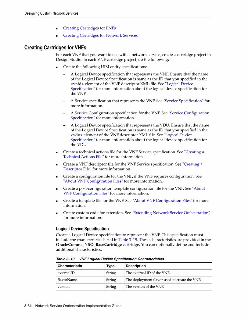
Designing Custom Network Services
3-34 Network Service Orchestration Implementation Guide
■ Creating Cartridges for PNFs
■ Creating Cartridges for Network Services
Creating Cartridges for VNFsFor each VNF that you want to use with a network service, create a cartridge project in Design Studio. In each VNF cartridge project, do the following:
■ Create the following UIM entity specifications:
– A Logical Device specification that represents the VNF. Ensure that the name of the Logical Device Specification is same as the ID that you specified in the <vnfd> element of the VNF descriptor XML file. See "Logical Device Specification" for more information about the logical device specification for the VNF.
– A Service specification that represents the VNF. See "Service Specification" for more information.
– A Service Configuration specification for the VNF. See "Service Configuration Specification" for more information.
– A Logical Device specification that represents the VDU. Ensure that the name of the Logical Device Specification is same as the ID that you specified in the <vdu> element of the VNF descriptor XML file. See "Logical Device Specification" for more information about the logical device specification for the VDU.
■ Create a technical actions file for the VNF Service specification. See "Creating a Technical Actions File" for more information.
■ Create a VNF descriptor file for the VNF Service specification. See "Creating a Descriptor File" for more information.
■ Create a configuration file for the VNF, if the VNF requires configuration. See "About VNF Configuration Files" for more information.
■ Create a post-configuration template configuration file for the VNF. See "About VNF Configuration Files" for more information.
■ Create a template file for the VNF. See "About VNF Configuration Files" for more information.
■ Create custom code for extension. See "Extending Network Service Orchestration" for more information.
Logical Device SpecificationCreate a Logical Device specification to represent the VNF. This specification must include the characteristics listed in Table 3–19. These characteristics are provided in the OracleComms_NSO_BaseCartridge cartridge. You can optionally define and include additional characteristics.
Table 3–19 VNF Logical Device Specification Characteristics
Characteristic Type Description
externalID String The external ID of the VNF.
flavorName String The deployment flavor used to create the VNF.
version String The version of the VNF.

Designing Custom Network Services
Designing and Onboarding Network Services, VNFs, and PNFs 3-35
Create a Logical Device specification to represent the VDU. This specification must include the characteristics listed in Table 3–20. These characteristics are provided in the OracleComms_NSO_BaseCartridge cartridge. You can optionally define and include additional characteristics.
See the Design Studio Help and the section on “Working with Characteristics” in the chapter, “Design Studio Overview” in UIM Concepts for more information about characteristics.
There are no rulesets required for the VNF and VDU Logical Device specifications. You can create custom rulesets to extend the default capabilities, however.
A VNF Logical Device specification must include the specification relationships listed in Table 3–21.
Associate the VNF tag to the VNF Logical Device specification to ensure that UIM correctly handles entities based on this specification. The VNF tag is provided in the OracleComms_NSO_BaseTags cartridge. See "Tagging Network Service Orchestration Specifications" for more information.
Associate the VDU tag to the VDU Logical Device specification to ensure that UIM correctly handles entities based on this specification. The VDU tag is provided in the OracleComms_NSO_BaseTags cartridge. See "Tagging Network Service Orchestration Specifications" for more information.
vimId String The ID of the VIM.
Table 3–20 VDU Logical Device Specification Characteristics
Characteristic Type Description
availabilityZoneName String The name of the availability zone where the VDU gets instantiated.
externalID String The external ID of the VDU.
flavorName String The deployment flavor used to create the VDU.
host String The host ID where VDU is instantiated.
imageId String The ID of the VDU Image.
imageName String The name of the VDU image.
imageVersion String The software version of the VDU image.
securityGroups String The security groups for the VDU.
Table 3–21 Logical Device Specification Relationships
Specification Name Description
DeviceInterface CPD Multiplicity is from 0 to 100.
This specification is available in the OracleComms_NSO_BaseCartridge cartridge.
ServiceSpecification user created Set this to the name of the VNF Service specification that you design.
Table 3–19 (Cont.) VNF Logical Device Specification Characteristics
Characteristic Type Description
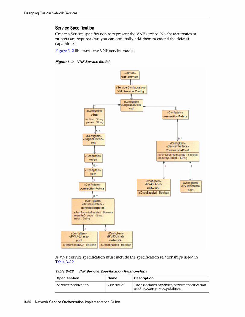
Designing Custom Network Services
3-36 Network Service Orchestration Implementation Guide
Service SpecificationCreate a Service specification to represent the VNF service. No characteristics or rulesets are required, but you can optionally add them to extend the default capabilities.
Figure 3–2 illustrates the VNF service model.
Figure 3–2 VNF Service Model
A VNF Service specification must include the specification relationships listed in Table 3–22.
Table 3–22 VNF Service Specification Relationships
Specification Name Description
ServiceSpecification user created The associated capability service specification, used to configure capabilities.

Designing Custom Network Services
Designing and Onboarding Network Services, VNFs, and PNFs 3-37
Apply the VNF tag to the VNF Service specification to ensure that UIM correctly handles entities based on this specification. The VNF tag is provided in the OracleComms_NSO_BaseTags cartridge. See "Tagging Network Service Orchestration Specifications" for more information.
Service Configuration SpecificationCreate a Service Configuration specification to accompany the VNF Service specification. The Service Configuration specification must include the configuration items listed in Table 3–23.
Define the specification options for the configuration items as shown in Table 3–24.
ServiceConfigurationSpecification
user created The associated service configuration specification.
Table 3–23 VNF Service Configuration Items
Name Parent Item Multiplicity Characteristics
vnf null Required None
connectionPoints vnf Required None
connectionPoint connectionPoints 0 to unbounded ■ isPortSecurityEnabled
■ securityGroups
vdus vnf Required None
vdu vdus 0 to unbounded None
vnfcs vdu Required None
vnfc vnfcs 0 to unbounded None
connectionPoints vnfc Required None
connectionPoint connectionPoints 0 to unbounded ■ isPortSecurityEnabled
■ securityGroups
■ order
port connectionPoint Required None
network connectionPoint Required isDhcpEnabled
Table 3–24 VNF Service Configuration Specification Options
ItemItem Option Type Specification Specification Type
vnf Assignment VNF Logical Device specification
connectionPoint Reference CPD Device Interface specification
vdu Assignment VDU Logical Device specification
vnfc None None None
port Reference IPv4Address IPv4Address specification
network Reference IPv4Subnet IPv4Subnet specification
Table 3–22 (Cont.) VNF Service Specification Relationships
Specification Name Description

Designing Custom Network Services
3-38 Network Service Orchestration Implementation Guide
Associate the following rulesets with the Service Configuration specification. These rulesets are included in the OracleComms_NSO_BaseCartridge cartridge:
■ IssueVNFServiceConfig_NSOBaseRulesetExtPt
■ AutomateVNFServiceConfig_NSOBaseRulesetExtPt
■ Cancel_VNFServiceConfigRulesetExtPt
■ CompleteVNFServiceConfig_NSOBaseRulesetExtPt
Creating Cartridges for PNFsFor each PNF that you want to use with a network service, create a cartridge project in Design Studio. In each PNF cartridge project, do the following:
■ Create the following UIM entity specifications:
– A Logical Device specification that represents the PNF. See "Logical Device Specification".
– A Service specification that represents the PNF service. See "Service Specification".
– A Service Configuration specification for the PNF service. See "Service Configuration Specification".
■ Create a technical actions file for the PNF Service specification. See "Creating a Technical Actions File" for more information.
■ Create a network service descriptor file for the Network Service specification. See "Creating a Descriptor File" for more information.
■ Create custom code for extension. See "Extending Network Service Orchestration" for more information.
Logical Device SpecificationCreate a Logical Device specification to represent the PNF. This specification must include the characteristics listed in Table 3–25. These characteristics are provided in the OracleComms_NSO_BaseCartridge cartridge. You can optionally define and include additional characteristics. See the Design Studio Help and the section on “Working with Characteristics” in the chapter, “Design Studio Overview” in UIM Concepts for more information about characteristics.
Associate the following rulesets with the PNF Logical Device specification. These rulesets are included in the OracleComms_NSO_BaseCartridge cartridge.
■ CreatePNF_Ruleset. This ruleset validates the create PNF request.
Table 3–25 PNF Logical Device Specification Characteristics
Characteristic Type Description
ipAddress String The IP address of the PNF.
password String The password of the PNF.
username String The username of the PNF.
sshkey String The ssh key for the PNF.
This characteristic is available in the PNF sample cartridge.
sslEnabled Boolean Indicates whether SSL is enabled for the PNF or not.

Designing Custom Network Services
Designing and Onboarding Network Services, VNFs, and PNFs 3-39
■ UpdatePNF_Ruleset. This ruleset validates the update PNF request.
■ CreateEMS_Ruleset. This ruleset validates the create EMS request.
■ UpdateEMS_Ruleset. This ruleset validates the update EMS request.
A PNF Logical Device specification must include the specification relationships listed in Table 3–26.
Apply the following tags to the PNF Logical Device specification to ensure that UIM correctly handles entities based on this specification. These tags are provided in the OracleComms_NSO_BaseTags cartridge.
■ PNF
■ EMS
See "Tagging Network Service Orchestration Specifications" for more information.
Service SpecificationCreate a Service specification to represent the PNF service. No characteristics or rulesets are required, but you can optionally add them to extend the default capabilities.
Figure 3–3 shows how a PNF service is modeled.
Table 3–26 PNF Logical Device Specification Relationships
Specification Name Description
DeviceInterfaceSpecification
CPD Multiplicity is from 0 to 100.
This specification is available in the OracleComms_NSO_BaseCartridge cartridge.
ServiceSpecification user created Set this to the name of the PNF Service specification that you design.

Designing Custom Network Services
3-40 Network Service Orchestration Implementation Guide
Figure 3–3 PNF Service Model
A PNF Service specification must include the specification relationships listed in Table 3–27.
Apply the PNF tag to the PNF Service specification to ensure that UIM correctly handles entities based on this specification. The PNF tag is provided in the OracleComms_NSO_BaseTags cartridge. See "Tagging Network Service Orchestration Specifications" for more information.
Service Configuration SpecificationCreate a Service Configuration specification to accompany the PNF Service specification. The Service Configuration specification must include the configuration items listed in Table 3–28.
Define the specification options for the configuration items as shown in Table 3–29.
Table 3–27 PNF Service Specification Relationships
Specification Name Description
ServiceConfigurationSpecification
Cisco_xRV_Service_Config
The associated service configuration specification.
Table 3–28 PNF Service Configuration Items
Item Parent Item Multiplicity Characteristics
pnf null Required None
ConnectionPoint pnf 1 to 100 None
port ConnectionPoint Required None

Designing Custom Network Services
Designing and Onboarding Network Services, VNFs, and PNFs 3-41
Associate the following rulesets with the Service Configuration Version specification. These rulesets are included in the OracleComms_NSO_BaseCartridge cartridge.
■ IssuePNFServiceConfig_NSOBaseRulesetExtPt
■ AutomatePNFServiceConfig_NSOBaseRulesetExtPt
■ Cancel_PNFServiceConfigRulesetExtPt
■ CompletePNFServiceConfig_NSOBaseRulesetExtPt
Creating Cartridges for Network ServicesFor each network service, create a cartridge project in Design Studio. In the cartridge project for the network service, do the following:
■ Create the following UIM entity specifications:
– A Service specification to represent the network service. Ensure that the name of the Service Specification is same as the ID that you specified in the <nsd> element of the network service descriptor XML file. See "Network Service Specification".
– A Service Configuration specification to accompany the network service specification. See "Network Service Configuration Specification".
■ Create a technical actions file for the Network Service specification. See "Creating a Technical Actions File" for more information.
■ Create a network service descriptor file for the Network Service specification. See "Creating a Descriptor File" for more information.
■ Create a custom properties file for the Network Service specification. See "Setting Network Service Descriptor Properties" for more information.
■ Create custom code for extension. See "Extending Network Service Orchestration" for more information.
Network Service SpecificationCreate a Network Service specification to represent the network service.
Figure 3–4 illustrates the network service model.
Table 3–29 PNF Service Configuration Specification Options
Item Item Option Type Specification
pnf Assignment Logical Device
ConnectionPoint Reference DeviceInterface
port Reference IPv4Address

Designing Custom Network Services
3-42 Network Service Orchestration Implementation Guide
Figure 3–4 Network Service Model
The Network Service specification must include the characteristics listed in Table 3–30. These characteristics are provided in the OracleComms_NSO_BaseCartridge cartridge.
The Network Service specification does not require any rulesets, but you can create custom rulesets to extend the default capabilities.
The Network Service specification must include the specification relationships listed in Table 3–31.
Table 3–30 Network Service Specification Characteristics
Characteristic Type Description
dataCenterName String The name of the data center.
flavorName String The name of the service flavor.
serverGroup String The name of the server group.
vimId String The unique identifier of VIM.

Designing Custom Network Services
Designing and Onboarding Network Services, VNFs, and PNFs 3-43
Apply the NetworkService tag to the Network Service specification to ensure that UIM correctly handles entities based on this specification. This tag is provided in the OracleComms_NSO_BaseTags cartridge. See "Tagging Network Service Orchestration Specifications" for more information.
Network Service Configuration SpecificationCreate a Service Configuration specification to accompany the Network Service specification.
The Service Configuration specification must include the configuration items listed in Table 3–32.
Define the specification options for the configuration items as shown in Table 3–33.
Table 3–31 Network Service Specification Relationships
Specification Name Description
ServiceConfigurationSpecification
user created This is the associated service configuration specification.
Table 3–32 Network Service Configuration Items
Item Parent Item Multiplicity Characteristics
virtualLinks null Required None
virtualLink virtualLinks 0-unbounded isReferedByNSO
vnfs null Required None
vnf vnfs 0 to unbounded None
vnfService vnf Required action
pnfs null Optional None
pnf pnfs 0 to unbounded None
pnfService pnf Required None
endPoints null Required None
endPoint endPoints 1 to unbounded None
vnffgs null Required None
vnffg vnffgs 0 to unbounded name
nfp vnffg 0 to unbounded ■ name
■ externalID
sourceEndPoint nfp Optional. 0 to 1. None
targetEndPoint nfp Optional. 0 to 1. None
Table 3–33 Network Service Configuration Specification Options
Item Item Option Type Specification Specification Type
virtualLinks None None None
virtualLink Reference IPv4Subnet IPv4Subnet specification
vnfs None None None
vnf Reference VNF Logical Device Logical Device specification

Designing Custom Network Services
3-44 Network Service Orchestration Implementation Guide
Associate the following rulesets with the Service Configuration Version specification. These rulesets are provided in the OracleComms_NSO_BaseCartridge cartridge.
■ AutomateNetworkServiceConfig_NSOBaseRulesetExtPt
■ IssueNetworkServiceConfig_NSOBaseRulesetExtPt
■ CompleteNetworkServiceConfig_NSOBaseRulesetExtPt
■ CancelNetworkServiceConfig_NSOBaseRulesetExtPt
vnfService Assignment VNF Service Service specification
pnfs None None None
pnf Reference PNF Logical Device Logical Device specification
pnfService Assignment PNF Service Service specification
endPoints None None None
endPoint Reference NetworkServiceEndPoint
Custom Object specification
vnffgs None None None
vnffg None None None
nfp None None None
sourceEndPoint Reference NetworkServiceEndPoint
Custom Object specification
targetEndPoint Reference NetworkServiceEndPoint
Custom Object specification
Table 3–33 (Cont.) Network Service Configuration Specification Options
Item Item Option Type Specification Specification Type

4
Working with Network Services, VNFs, VDUs, and PNFs 4-1
4Working with Network Services, VNFs, VDUs,and PNFs
This chapter provides information about working with network services, Virtual Network Functions (VNFs), Virtual Deployment Units (VDUs), and Physical Network Functions (PNFs) in Oracle Communications Network Service Orchestration.
To work with network services, VNFs, VDUs, and PNFs in Network Service Orchestration, you can use either the UIM user interface or the REST APIs. See UIM Help for instructions about performing tasks using the user interface.
When you use REST APIs, you use a REST API client and provide values for the required parameters in the API request. The values and the parameters are defined in the network service and VNF descriptor files that you created in Design Studio. See "Network Service Orchestration RESTful API Reference" for details about the REST APIs that you can use to perform various tasks.
You perform the following tasks related to network services, VNFs, and PNFs:
■ Instantiating Network Services
■ Terminating Network Services
■ Viewing Progress of Life-cycle Actions
■ Modifying Network Services
■ Scaling VNFs
■ Healing VNFs
■ Working with PNFs in Network Services
■ Retrieving Details About Network Services, VNFs, PNFs, and Descriptors
■ Registering VNFs with Third-Party Systems
Instantiating Network ServicesYou instantiate a network service to start a VNF on the network. A network service can have multiple VNFs that are connected to each other. When you instantiate a network service that has multiple VNFs, all the VNFs in the network service are
Note: Based on the configurations that the VNFs in the network service require, some VNF life cycle operations may take some time to complete. In UIM and in your VIM, the resources may not be created, deleted, or updated immediately after you send the API request or complete the operation using the user interface.

Instantiating Network Services
4-2 Network Service Orchestration Implementation Guide
started on the network. You can also include PNFs in your network services. See "Working with PNFs in Network Services" for information about including PNFs in network services.
Before you instantiate a network service, ensure that your VIM is registered and the data center resources that your VIM manages are discovered. If you use multiple VIMs, register all your VIMs and discover the resources that the VIMs manage. See "Discovering VIM Resources" for information about discovering VIM resources.
If you use multiple VIMs to instantiate your network services, do the following:
■ In UIM, create an Inventory Group entity and associate the VDC custom object that was generated during the discovery of VIM resources to the inventory group. See UIM Help for instructions.
■ Create a ServiceLocation entity based on the Place specification and associate it to the Inventory Group entity.
■ When you instantiate a network service, specify the service location of the VDC in which you want to instantiate the network service.
After you instantiate a network service, verify the following in UIM:
■ The network service and its configurations are created and are in In Service status. You can see this in the Network Service Summary page of the network service.
■ The VNF service and its configurations are created and associated to the network service.
■ The VNFs and their constituent VDUs, which are represented as logical devices, are created.
■ The PNFs, which are represented as logical devices, are created.
■ The specified networks are either created or referenced.
■ The details of the endpoints are updated in the service configuration.
In your VIM, verify the following:
■ The VDU instances of the VNFs are up and running.
■ The specified networks are either created or referenced.
■ The VDUs are linked to the networks.
Based on the configurations you defined in the network service and the VNF and PNF descriptor files, Network Service Orchestration does the following tasks during the instantiation of a network service:
■ Finds the best suitable data center for the network service from among the data centers that you registered.
■ Performs resource orchestration to find the best suitable availability zone where constituent VNFs can be deployed.
■ Creates new networks or references existing networks that are required for connectivity among the VNFs.
■ Manages IP addresses of all the resources.
■ Configures the VNFs based on pre-defined parameters. See "About VNF Configuration Files" for more information.
■ If the network service includes a PNF, configures the PNF and checks access to the PNF using the management IP address.

Instantiating Network Services
Working with Network Services, VNFs, VDUs, and PNFs 4-3
■ If you integrated a monitoring engine, configures the monitoring engine to trigger alarms for VNFs that reach a specified threshold to enable healing of VNFs.
■ If you integrated an SDN controller, configures routing paths for end-to-end packet flow.
See "Modifying Network Services" for information about adding and removing VNFs, endpoints, and PNFs in network services.
Managing Failed Life-Cycle ActionsIf a life-cycle action fails to complete successfully, Network Service Orchestration either stops the action or rolls back the changes so that the resource assignments revert to the previous state. It may be necessary to complete manual actions to resolve the errors and perform the life-cycle action again.
NSO automatically handles rollback for problems that arise during the following activities:
■ Designing a network service
■ Creating networks, subnets, and ports
■ Deploying and configuring virtual machines
However, there are some scenarios where Network Service Orchestration does not rollback changes when a life-cycle action fails to complete successfully.
For example, consider a scenario where you instantiate a network service that includes four VNFs and only three of the VNFs get deployed during the network service instantiation process. Even if a single VNF is not deployed, Network Service Orchestration does not roll back the entire network service instantiation process, and the network service remains in PENDING status. In this case, you must either accept the partially instantiated network service or roll back the network service.
Accepting Partially Instantiated Network ServicesTo accept the partially instantiated network service:
1. In the Network Service Orchestration group of the navigation section, in the Orchestration subgroup, click the Orchestration Requests link.
The search page for Orchestration Requests appears.
2. In the Search Results section, enter the ID of the orchestration request and click Search.
3. In the Search Results section, click the ID of the orchestration request.
The Orchestration Request Details page appears.
4. Click Edit.
5. In the Description field, enter a description for the orchestration request. For example, The VNF Request (ID:75001) failed to complete successfully. Network Service is created partially. Need to call Add VNF REST API to add the failed VNF.
You add a description to maintain a history of the orchestration request.
Note: The example scenario included in this section is applicable to both network service instantiation and network service termination processes.

Modifying Network Services
4-4 Network Service Orchestration Implementation Guide
6. Click Save and Close.
7. From the Actions menu, select Complete Hierarchy.
The status of the orchestration request changes to Completed and the status of the corresponding service changes to In Service.
Rolling Back Partially Instantiated Network ServicesTo roll back the partially instantiated network service:
1. Accept the partially instantiated network service. See "Accepting Partially Instantiated Network Services" for more information.
2. Terminate the partially instantiated network service.
Adding Failed VNFs to Partially Instantiated Network ServicesTo add the failed VNFs to the partially instantiated network service:
1. Accept the partially instantiated network service. See "Accepting Partially Instantiated Network Services" for more information.
2. In the Events section, view the logs to identify the cause of the orchestration request failure, and then perform any required actions.
3. Add the failed VNFs by calling the REST API to add VNFs. See "Add VNF to Network Service" for more information.
Modifying Network ServicesYou can modify a network service that you have saved but not instantiated. You modify a network service to add or remove endpoints, VNFs, and PNFs in the network service. You add a VNF to a network service to enable the network service to deliver additional service capabilities. You remove a VNF from a network service when it is no longer required. Similarly, you can add and remove endpoints and PNFs in your network services.
Before the network service has been instantiated, you can perform the following tasks using the user interface:
■ Add VNFs to network services
■ Remove VNFs from network services
■ Add PNFs to network services
■ Remove PNFs from network services
■ Add endpoints to network services
■ Remove endpoints from network services
See UIM Help for instructions about performing tasks using the user interface.
After the network service has been instantiated, you can perform the following tasks using the REST APIs:
■ Add VNFs to network services
■ Remove VNFs from network services
See "Network Service Orchestration RESTful API Reference" for details about the Network Service Orchestration REST APIs that you can use to modify network services.

Terminating Network Services
Working with Network Services, VNFs, VDUs, and PNFs 4-5
Adding VNFs to Existing Network ServicesYou use REST APIs to add VNFs to a network service after the network service has been instantiated.
After you add a VNF to a network service, do the following:
1. In UIM, verify the following:
■ The network service is updated with a new service configuration version showing the VNF that you added.
■ The status of the new service configuration version shows completed.
■ A new VNF instance is created and new instances of its constituent VDUs are also created.
2. In your VIM, verify that all the constituent VDU instances for the new VNF are created.
Removing VNFs from Existing Network ServicesYou use REST APIs to remove VNFs from a network service after the network service has been instantiated.
After you remove a VNF from a network service, do the following:
1. In UIM, verify the following:
■ The network service is updated with a new service configuration version showing that the VNF is deleted.
■ The status of the service configuration version shows completed.
■ The VNF instance is deleted and instances of its constituent VDUs are also deleted.
2. In your VIM, verify that the constituent VDU instances for the VNF are deleted and the resources that were assigned to the VDUs are freed up.
Terminating Network ServicesYou terminate a network service to deactivate all the constituent VNFs in the network service. When you terminate a network service, all the resources that were allocated to the VNFs are released and become available for consumption by other network services.
After you terminate a network service, do the following:
1. In UIM, verify the following:
■ The status of the network service and the VNF and PNF services is changed to Disconnected.
■ The statuses of the logical devices corresponding to the VNFs and their associated VDUs are changed to Unassigned
■ The statuses of the logical devices corresponding to the associated PNFs are changed to Unassigned.
2. In your VIM, verify that all the VDU instances of all the VNFs are deleted and all the allocated resources are released.
Viewing Progress of Life-cycle Actions
4-6 Network Service Orchestration Implementation Guide
Viewing Progress of Life-cycle ActionsWhen you perform a life-cycle action for a network service, the Network Service summary page displays a progress bar indicating that the life-cycle action is in progress. At the top of the Network Service Summary page, messages appear informing you about the statuses and timestamps of the various intermediate processes that are run to complete the life-cycle action. After the life-cycle action is completed successfully, in the Network Service Summary page, the Status field displays the final status of the network service.
When you perform a life-cycle action for a VNF, at the top of the VNF Summary page, a message appears informing you that the VNF has been submitted for the relevant life-cycle action. After the process is completed successfully, a message appears informing you that the VNF has been processed for the life-cycle action you performed.
Network Service Orchestration displays notifications to indicate the progress of the following life-cycle actions:
■ Creating Network Services
■ Instantiating Network Services
■ Terminating Network Services
■ Adding VNFs to Network Services
■ Removing VNFs from Network Services
■ Adding Endpoints to Network Services
■ Removing Endpoints from Network Services
■ Adding PNFs to Network Services
■ Removing PNFs from Network Services
■ Canceling Network Services
■ Rebooting Virtual Network Functions
■ Replacing Virtual Network Functions
■ Scaling Virtual Network Functions
■ Rebooting Virtual Deployment Units
You can extend the progress notifications for the life-cycle actions by implementing a custom notification manager. See "Implementing a Custom Notification Manager" for more information about implementing a custom notification manager.
Scaling VNFsYou scale VNFs to either add new instances of the constituent VDUs of the VNF in a network service or remove instances of the constituent VDUs of the VNF in a network service.
Network Service Orchestration provides the following VNF scale options:
■ Scale Out: Enables you to add additional instances of each constituent VDU of the VNF in the network service based on the scale quantity defined for the constituent VDUs in the VNF descriptor. As part of VNF scale out, you can add VDU instances only up to the maximum limit defined for the constituent VDUs in the VNF descriptor. Even if one of the VDUs in a VNF has reached its maximum instance limit, and the other VDUs in that VNF have not reached their maximum

Healing VNFs
Working with Network Services, VNFs, VDUs, and PNFs 4-7
instance limit, Network Service Orchestration does not allow you to further scale-out the VNF.
■ Scale In: Enables you to remove existing instances of each constituent VDU of the VNF in the network service based on the scale quantity defined for the constituent VDUs in the VNF descriptor. As part of VNF scale in, you can remove VDU instances only up to the minimum limit defined for the constituent VDUs in the VNF descriptor. Even if one of the VDUs in a VNF has reached its minimum instance limit, and the other VDUs in that VNF have not reached their minimum instance limit, Network Service Orchestration does not allow you to further scale-in the VNF.
See "Describing VNF Deployment Flavors" for more information.
Healing VNFsYou can heal a VNF by either rebooting or replacing the virtual machine on which the VNF is deployed. Similarly, you can heal a VDU by rebooting the virtual machine on which the VDU is deployed.
When you reboot a VNF, all the constituent VDUs of the VNF are rebooted. Similarly, when you replace a VNF, all the constituent VDUs of the VNF are replaced.
When you heal a VNF by replacing it, the new VDUs of the VNF may come up in a different host. Network Service Orchestration performs resource orchestration to deduce the resources from the new host and the availability zone and adds up the resources count to the host.
To heal a VNF:
1. Ensure that you have defined the assurance parameters for the VNFs in the VNF descriptor file. See "Describing VNF Deployment Flavors" for information about defining assurance parameters.
2. Do one of the following:
■ Use the user interface to reboot or replace the VNF. See UIM Help for instructions.
■ Use the user interface to reboot a specific VDU of a VNF. See UIM Help for instructions.
■ Call the RESTful API. See "Network Service Orchestration RESTful API Reference" for more information.
3. In your VIM, verify that the VNF you rebooted or replaced is listed as active and running.
4. In your VIM, verify that the VDU you rebooted or replaced is listed as active and running.
Monitoring VNFsYou monitor VNFs in a network service to track their performance and take actions based on their CPU utilization, number of requests handled, and other key performance indicator (KPI) parameters.
To monitor VNFs, you configure and use monitoring engines. You also configure and specify the relevant parameters in the VNF descriptor file. See "Describing VNF Deployment Flavors" for information about defining assurance parameters for monitoring and healing a VNF.

Working with PNFs in Network Services
4-8 Network Service Orchestration Implementation Guide
By default, Network Service Orchestration supports integration with OpenStack Ceilometer, which monitors VNFs and reboots failed VNFs automatically based on KPI thresholds that are defined in the network service descriptor file.
You can integrate other third-party monitoring engines by using the extensions provided in Network Service Orchestration. See "Implementing a Custom Monitoring Engine" for more information about implementing a third-party monitoring engine.
About the Monitoring Tabs in the User InterfaceWhen you create specifications for your VNFs and network services in Design Studio, you can add characteristics to the specifications to capture URLs of web pages of your monitoring systems. You can define the characteristics to capture any number of URLs of web pages. See Design Studio documentation about working with characteristics and specifications.
In the UIM user interface, when you create network services, you specify the URLs of web pages of your monitoring systems. After the network service is instantiated, each URL that you specified for your monitoring system displays an embedded page in a tab in the Network Service Summary page.
You can use the monitoring tabs to view service topologies of your network services, and the following metrics about your VNFs:
■ CPU
■ Memory
■ Disk space
See UIM Help for more information about the monitoring tabs.
Working with PNFs in Network ServicesYou can include Physical Network Functions (PNFs) in your network services.
To include PNFs in a network service, do the following:
1. If your PNF is managed by an EMS, register the Element Management System (EMS) with Network Service Orchestration by using the REST API. See "Network Service Orchestration RESTful API Reference" for information about registering EMSs.
2. Register the PNF with Network Service Orchestration by using the REST API.
3. When you create a network service in the user interface, add the PNF to the network service. See UIM Help for instructions about adding PNFs to network services.
If you use REST APIs to instantiate a network service with PNFs, specify the details of the PNFs in the API request. See "Network Service Orchestration RESTful API Reference" for information about the API request.
Retrieving Details About Network Services, VNFs, PNFs, and DescriptorsYou can retrieve and view details about your network services, VNFs, PNFs, network service descriptors, and VNF descriptors by using the user interface and the REST APIs. In the user interface, you can search for and view details by using standard UIM techniques. See UIM Help for more information.

Registering VNFs with Third-Party Systems
Working with Network Services, VNFs, VDUs, and PNFs 4-9
Network Service Orchestration provides RESTful APIs that you can call to retrieve and view different types of information about your network services, VNFs, and PNFs. For details about the RESTful APIs, see "Network Service Orchestration RESTful API Reference".
Registering VNFs with Third-Party SystemsYou can register the instantiated VNFs with third-party systems, such as element management systems (EMSs) and configuration management systems (CMSs). After the VNFs are registered, the third-party systems can discover and manage the VNFs.
Network Service Orchestration provides a reference implementation to integrate with IP Service Activator to discover and manage the instantiated VNFs using the Juniper_vSRX sample cartridge. See "Integrating Network Service Orchestration with IP Service Activator" for more information.

Registering VNFs with Third-Party Systems
4-10 Network Service Orchestration Implementation Guide

5
Implementing the Sample Network Services 5-1
5Implementing the Sample Network Services
[2] This chapter provides information about the sample network services that are provided with Network Service Orchestration.
Network Service Orchestration includes the following sample cartridges that you can use as references for designing and implementing your own network services:
■ Juniper_vSRX. This sample cartridge contains the Juniper vSRX firewall VNF to use with the network protection service.
■ Checkpoint_NG_FW. This sample cartridge contains the Checkpoint firewall VNF to use with the network protection service.
■ Cisco_xRV. This sample cartridge contains the Cisco XRV router PNF to use with the residential gateway network service or the network protection service.
■ OracleComms_SBC. This sample cartridge contains the Session Border Controller (SBC) VNF to use with the Proxy-Call Session Control Function (P-CSCF) network service.
■ NPaaS_NetworkService. This sample cartridge provides the functionality to implement a Network Protection as a Service (NPaaS) network service.
■ ResidentialGateway_NetworkService. This sample cartridge provides the functionality to implement a Residential Gateway network service
■ OracleComms_P-CSCF_NetworkService. This sample cartridge provides the functionality to implement a Proxy-Call Session Control Function (P-CSCF) network service.
Configuring the Juniper vSRX Base ImageBefore you implement the sample network services, you must configure the software image of the Juniper vSRX firewall VNF. You use this VNF with the Network Protection and the Residential Gateway network services.
To configure the Juniper vSRX base image:
1. Download the Juniper vSRX base image from Juniper’s web site.
2. Install OpenStack and source the tenant’s credentials file.
3. In OpenStack, upload the downloaded base image to the Glance repository by running the following command:
glance image-create --name vsrx-vmdisk-15.1X49-D40_base --is-public true --container-format bare --disk-format qcow2 --file media-vsrx-vmdisk-15.1X49-D40.6.qcow2

Configuring the Juniper vSRX Base Image
5-2 Network Service Orchestration Implementation Guide
where:
■ vsrx-vmdisk-15.1X49-D40_base is the name of the image uploaded into the repository
■ media-vsrx-vmdisk-15.1X49-D40.6.qcow2 is the name of the base image downloaded from the vendor’s web portal.
4. In OpenStack, create a flavor with the following specifications by running the following command:
Specifications:
■ Name: vsrx.medium
■ VCPUs: 2
■ Root Disk: 20 GB
■ Ephemeral Disk: 0 GB
■ RAM: 4096 MB
Command:
nova flavor-create vsrx.medium auto 4096 20 2
5. Boot the image by running the following command:
nova boot --flavor vsrx.medium --image vsrx-vmdisk-15.1X49-D40_base --nic net-ID=networkID vsrx_base_instance
where:
■ networkID is the ID of your management network in OpenStack.
■ vsrx-vmdisk-15.1X49-D40_base is the name of the base image that is uploaded into the repository.
■ vsrx_base_instance is the name of the vsrx instance you are spawning in OpenStack.
6. After the image boots up, navigate to the Instances console in OpenStack and run the following commands:
root@%cliroot>configroot#delete securityset system root-authentication plain-text-passwordNew password: Enter a passwordRetype new password:Enter a password
OpenStack prompts for a password.
7. Enter any password and run the following commands:
set system login user admin class super-user authentication plain-text-passwordNew password:passwordRetype new password:password
OpenStack prompts for a password.
8. Enter any password.
The username and the password that you specify here become the username and password of the VNF image that you specify in the VNF descriptor. Network

Configuring the Juniper vSRX Base Image
Implementing the Sample Network Services 5-3
Service Orchestration uses these credentials to update the configuration.
9. Run the following commands:
set system services netconf sshset interfaces fxp0 description "Managament Interface" unit 0 family inet dhcpset interfaces ge-0/0/0 description "Customer Interface" unit 0 family inet dhcpset interfaces ge-0/0/1 description "Internet interface" unit 0 family inet dhcpset security zones security-zone Customer host-inbound-traffic system-services pingset security zones security-zone Internet host-inbound-traffic system-services pingset security zones security-zone Customer interfaces ge-0/0/0.0 host-inbound-traffic system-services dhcp set security zones security-zone Customer interfaces ge-0/0/0.0 host-inbound-traffic system-services pingset security zones security-zone Internet interfaces ge-0/0/1.0 host-inbound-traffic system-services dhcpset security zones security-zone Internet interfaces ge-0/0/1.0 host-inbound-traffic system-services pingset routing-instances Traffic instance-type virtual-routerset routing-instances Traffic interface ge-0/0/0.0set routing-instances Traffic interface ge-0/0/1.0set groups security-rules security policies from-zone <*> to-zone <*> policy <*> then log session-init session-closeset security policies apply-groups security-rulesset security policies from-zone Customer to-zone Internet policy Customer-Internet-Access match source-address any destination-address any application anyset security policies from-zone Customer to-zone Internet policy Customer-Internet-Access then permitset security policies from-zone Internet to-zone Customer policy Deny-All match source-address any destination-address any application anyset security policies from-zone Internet to-zone Customer policy Deny-All then denyset security utm custom-objects url-pattern bad-sites value http://www.example.comset security utm custom-objects custom-url-category bad-category value bad-sitesset security utm feature-profile web-filtering juniper-local profile wf-profile custom-block-message "Website blocked by NPaaS. Powered by Oracle" default log-and-permit fallback-settings default block too-many-requests blockset security utm utm-policy utm-protect web-filtering http-profile wf-profilecommitexitexit
10. Create a snapshot of the running instance of the Juniper vSRX image by running the following command:
nova image-create --poll vsrx_base_instance vsrx-vmdisk-15.1X49-D40_updated
where:
■ vsrx_base_instance is the name of the vsrx instance
■ vsrx-vmdisk-15.1X49-D40_updated is the name of the vsrx image snapshot uploaded to OpenStack Glance.
Use this snapshot as the software image for instantiation of the Juniper vSRX VNF.

Implementing the Network Protection Service
5-4 Network Service Orchestration Implementation Guide
Implementing the Network Protection ServiceNetwork Service Orchestration provides sample cartridges that you can use as references for designing and implementing a network protection service.
The NPaaS_NetworkService sample cartridge contains the functionality to implement the sample Network Protection as a Service (NPaaS) network service.
The network protection service constitutes and uses the following VNFs:
■ Juniper vSRX firewall
The Juniper_vSRX sample cartridge contains the functionality to implement a Juniper vSRX firewall as a VNF.
■ Checkpoint firewall
The Checkpoint_NG_FW sample cartridge contains the functionality to implement a Checkpoint firewall as a VNF.
The network protection service requires and uses the following software components:
■ UIM 7.3.5 and the Network Service Orchestration 7.3.5 cartridges
■ OpenStack VIM, with Networking-SFC functionality
■ Software images of the firewall VNFs
To implement the network protection service:
1. Configure the Juniper vSRX base image. See "Configuring the Juniper vSRX Base Image" for instructions.
2. In OpenStack, create a tenant or reference an existing tenant with administrator privileges.
3. Reference an existing management network that can be shared by all the components of Network Service Orchestration.
The management network requires, at a minimum:
■ One IP address for each machine on which UIM is installed
■ One IP address for each virtual machine on which you want to bring up the VNFs
4. Connect the management network and the external network to a virtual router. This enables you to use floating IP addresses for providing access to the data center.
5. Reference an existing data network that connects all the VNF instances within the network service, and do the following:
■ Create the ingress endpoint and egress endpoint ports in the data network
■ Bring up the ingress gateway VM using the ingress endpoint port
■ Bring up the egress gateway VM using the egress endpoint port
6. Open the UIM_Home/config/nso.properties file and update the following parameters.
■ NSO_HOST: IPv4address. Specify the host on which UIM is installed. By default, Network Service Orchestration considers the host on which the UIM server is running. If the server is running on a private network that is unavailable to external network, specify a reachable IP address for the server.
■ NSO_USERNAME: username
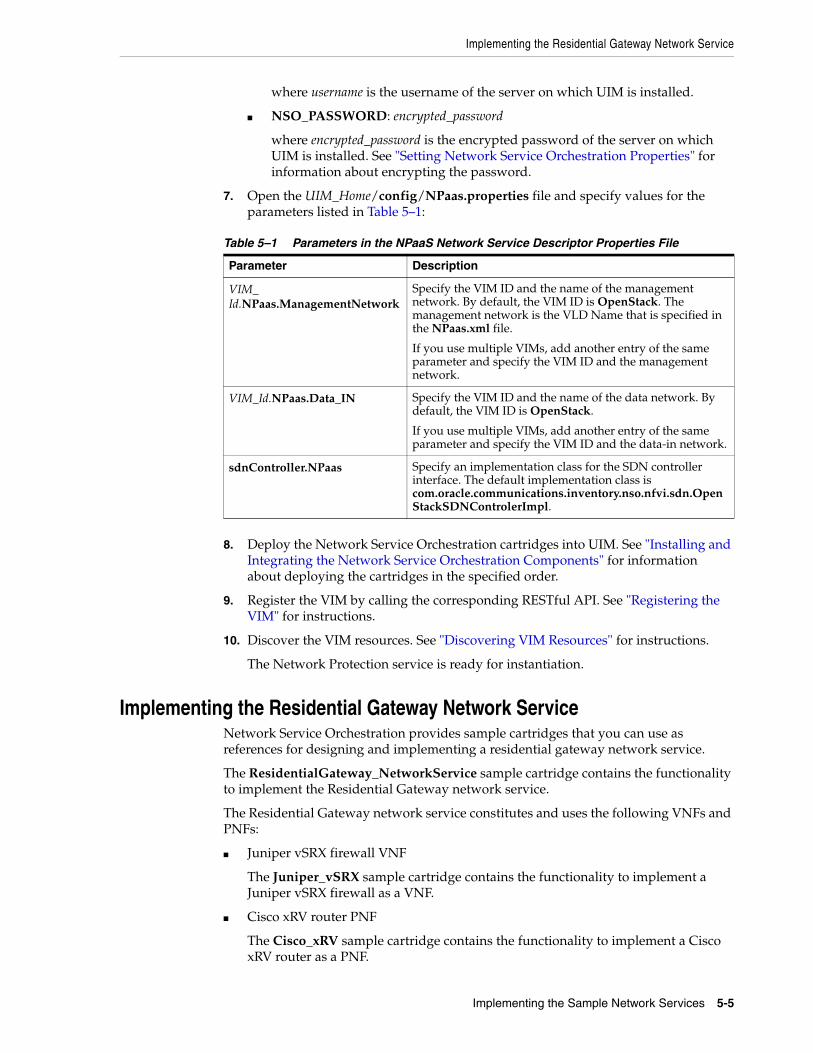
Implementing the Residential Gateway Network Service
Implementing the Sample Network Services 5-5
where username is the username of the server on which UIM is installed.
■ NSO_PASSWORD: encrypted_password
where encrypted_password is the encrypted password of the server on which UIM is installed. See "Setting Network Service Orchestration Properties" for information about encrypting the password.
7. Open the UIM_Home/config/NPaas.properties file and specify values for the parameters listed in Table 5–1:
8. Deploy the Network Service Orchestration cartridges into UIM. See "Installing and Integrating the Network Service Orchestration Components" for information about deploying the cartridges in the specified order.
9. Register the VIM by calling the corresponding RESTful API. See "Registering the VIM" for instructions.
10. Discover the VIM resources. See "Discovering VIM Resources" for instructions.
The Network Protection service is ready for instantiation.
Implementing the Residential Gateway Network ServiceNetwork Service Orchestration provides sample cartridges that you can use as references for designing and implementing a residential gateway network service.
The ResidentialGateway_NetworkService sample cartridge contains the functionality to implement the Residential Gateway network service.
The Residential Gateway network service constitutes and uses the following VNFs and PNFs:
■ Juniper vSRX firewall VNF
The Juniper_vSRX sample cartridge contains the functionality to implement a Juniper vSRX firewall as a VNF.
■ Cisco xRV router PNF
The Cisco_xRV sample cartridge contains the functionality to implement a Cisco xRV router as a PNF.
Table 5–1 Parameters in the NPaaS Network Service Descriptor Properties File
Parameter Description
VIM_Id.NPaas.ManagementNetwork
Specify the VIM ID and the name of the management network. By default, the VIM ID is OpenStack. The management network is the VLD Name that is specified in the NPaas.xml file.
If you use multiple VIMs, add another entry of the same parameter and specify the VIM ID and the management network.
VIM_Id.NPaas.Data_IN Specify the VIM ID and the name of the data network. By default, the VIM ID is OpenStack.
If you use multiple VIMs, add another entry of the same parameter and specify the VIM ID and the data-in network.
sdnController.NPaas Specify an implementation class for the SDN controller interface. The default implementation class is com.oracle.communications.inventory.nso.nfvi.sdn.OpenStackSDNControlerImpl.

Implementing the Residential Gateway Network Service
5-6 Network Service Orchestration Implementation Guide
The Residential Gateway network service requires and uses the following software components:
■ UIM 7.3.5 and the Network Service Orchestration 7.3.5 cartridges
■ OpenStack VIM
■ Software image of the Juniper firewall VNF
■ Cisco xRV PNF. Ensure that the PNF is up and running on a management IP address.
To implement the Residential Gateway network service:
1. Configure the Juniper vSRX base image. See "Configuring the Juniper vSRX Base Image" for instructions.
2. In OpenStack, create a tenant or reference an existing tenant with administrator privileges.
3. Reference an existing management network that can be shared by all the components of Network Service Orchestration.
4. Specify the details of the external network in the Endpoints tab. By default, NSO creates the floating IP address on the external network for providing access to the PNF. However, if you specify the floating IP address in the IP Address field, NSO uses this IP address for providing access to the PNF.
5. Open the UIM_Home/config/ResidentialGateway.properties file and specify values for the parameters listed in Table 5–2.
6. Deploy the Network Service Orchestration cartridges into UIM. See "Installing and Integrating the Network Service Orchestration Components" for information about deploying the cartridges in the specified order.
7. Register the PNF by using the REST API. See "Network Service Orchestration RESTful API Reference" for a sample request for registering PNFs.
Table 5–2 Parameters in the Residential Gateway Descriptor Properties File
Parameter Description
VIM_Id.ResidentialGateway.ManagementNetwork
Specify the VIM ID and the name of the management network. By default, the VIM ID is OpenStack. The management network is the VLD Name that is specified in the ResidentialGateway.xml file.
If you use multiple VIMs, add another entry of the same parameter and specify the VIM ID and the management network.
VIM_Id.ResidentialGateway.Data_IN
Specify the VIM ID and the name of the data-in network. By default, the VIM ID is OpenStack.
If you use multiple VIMs, add another entry of the same parameter and specify the VIM ID and the data-in network.
VIM_Id.ResidentialGateway.Data_OUT
Specify the VIM ID and the name of the data-out network. By default, the VIM ID is OpenStack.
If you use multiple VIMs, add another entry of the same parameter and specify the VIM ID and the data-out network.
sdnController.ResidentialGateway
Specify an implementation class for the SDN controller interface. The default implementation class is com.oracle.communications.inventory.nso.nfvi.sdn.OpenStackSDNControlerImpl.

Implementing the Proxy-Call Session Control Function Network Service
Implementing the Sample Network Services 5-7
See "Working with PNFs in Network Services" for more information about working with PNFs.
8. Register the VIM by using the REST API. See "Registering the VIM" for instructions.
9. Discover the VIM resources. See "Discovering VIM Resources" for instructions.
10. To enable connectivity between the VNF and PNF, the VNF is assigned with a floating IP address. Configure the static routes corresponding to the floating IP in the PNF manually or by extending the cartridges.
The Residential Gateway network service is ready for instantiation.
Implementing the Proxy-Call Session Control Function Network ServiceNetwork Service Orchestration provides sample cartridges that you can use as references for designing and implementing a Proxy-Call Session Control Function (P-CSCF) network service.
The OracleComms_P-CSCF_NetworkService sample cartridge contains the functionality to implement the sample P-CSCF network service.
The P-CSCF network service constitutes and uses the following VNF:
■ Session Border Controller (SBC) device
The OracleComms_SBC sample cartridge contains the functionality to implement an SBC device as a VNF.
The P-CSCF network service requires and uses UIM 7.3.5 and the Network Service Orchestration 7.3.5 cartridges.
To implement the P-CSCF network service:
1. In Oracle Communications Application Orchestrator, add and configure a hierarchical service configuration (HSC). When adding an HSC ensure that you select ASBC-Standalone in the CNFD field of the Add hierarchy service configuration pane. See Oracle Communications Application Orchestrator User Guide for more information.
2. Reference an existing management network that can be shared by all the components of Network Service Orchestration.
The machine on which Oracle Communications Application Orchestrator is installed requires, at a minimum, one management network that has at least one IP address for each virtual machine on which you want to bring up the SBC VNF.
3. In Oracle Communications Application Orchestrator, create the data-in and data-out networks.
See Oracle Communications Application Orchestrator Installation Guide for information about creating the management, data-in, and data-out networks.
4. Open the UIM_Home/config/P-CSCF.properties file and specify values for the parameters listed in Table 5–3.
Table 5–3 Parameters in the P-CSCF Network Service Descriptor Properties File
Parameter Description
P-CSCF.ManagementNetwork Specify the name of the Network Service Orchestration management network.

Implementing the Proxy-Call Session Control Function Network Service
5-8 Network Service Orchestration Implementation Guide
5. Open the UIM_Home/config/aoconfig.properties file and specify values for the parameters listed in Table 5–4.
6. Open the UIM_Home/config/SBC.properties file and set the following recommended values for the parameters:
SBC.vLink.SLRM_IP=198.51.100.1
P-CSCF.Data_IN Specify the name of the Network Service Orchestration data-in network.
P-CSCF.Data_OUT Specify the name of the Network Service Orchestration data-out network.
nso.aopoller.maxExecutions.Operational_Ready
Specify the maximum number of times Network Service Orchestration should poll the Application Orchestrator application to determine the status of the VNF instantiation/deployment.
nso.aopoller.maxExecutions.Not_Configured
Specify the maximum number Network Service Orchestration should poll the Application Orchestrator application to determine the status of VNF termination/undeployment.
nso.aopoller.deploy.finalState Specify the final status of the VNF deployment.
Table 5–4 Parameters in the Application Orchestrator Configuration Properties File
Parameter Description
ocao.host Specify the name of the host on which Oracle Communications Application Orchestrator is installed.
ocao.port Specify the port number of the machine on which Application Orchestrator is installed.
ocao.scheme Specify the scheme name of the Application Orchestrator.
ocao.username Specify the user name of the Application Orchestrator application.
ocao.password Specify the password of the Application Orchestrator application.
ocao.restapi.url Specify the REST API URL along with its version.
ocao.ManagementNetwork Specify the name of the Application Orchestrator management network.
ocao.Data_IN Specify the name of the Application Orchestrator data-in network.
ocao.Data_OUT Specify the name of the Application Orchestrator data-out network.
ocao.nfrc.appName Specify the name of the application that deployed the VNF.
ocao.nfrc.appGlobalId Specify the global ID of the application that deployed the VNF.
Note: Consult with the administrator of Oracle Communications Application Orchestrator before changing the parameter values.
Table 5–3 (Cont.) Parameters in the P-CSCF Network Service Descriptor Properties File
Parameter Description

Integrating Network Service Orchestration with IP Service Activator
Implementing the Sample Network Services 5-9
SBC.vLink.SipIp=198.51.100.2SBC.vLink.TunnelRemoteIp=198.51.100.3SBC.vLink.GatewayIp=198.51.100.21
Specify the following parameter values as name-value pairs:
SBC.vScalability.deviceInfo.param.1=userPassword,abc12345!SBC.vScalability.deviceInfo.param.2=adminPassword,abc12345!SBC.vScalability.deviceInfo.param.3=configPassword,acmepacketSBC.vScalability.deviceInfo.param.4=deviceGroup,HomeSBC.vScalability.deviceInfo.param.5=snmpCommunity,publicSBC.vScalability.deviceInfo.param.6=useDeviceCluster,falseSBC.vScalability.deviceInfo.param.7=entitlement:capacity:capacity,1000SBC.vScalability.deviceInfo.param.8=entitlement:feature:FEATURE_ACCOUNTING,trueSBC.vScalability.deviceInfo.param.9=entitlement:feature:FEATURE_IPV6,trueSBC.vScalability.deviceInfo.param.10=entitlement:feature:FEATURE_SAG,trueSBC.vScalability.deviceInfo.param.11=entitlement:feature:FEATURE_QOS,trueSBC.vScalability.deviceInfo.param.12=entitlement:feature:FEATURE_SESSION_RECORDING,trueSBC.vScalability.deviceInfo.param.13=entitlement:feature:FEATURE_IWF,trueSBC.vScalability.deviceInfo.param.14=entitlement:feature:Routing,trueSBC.vScalability.deviceInfo.param.15=entitlement:feature:Policy Server,trueSBC.vScalability.dcParameter.param.1=bootparams.gateway,198.51.100.21SBC.vScalability.dcParameter.param.2=bootparams.netmask0,192.0.2.254SBC.vScalability.dcParameter.param.3=bootparams.vlan,0
7. Deploy the Network Service Orchestration cartridges into UIM. See "Installing and Integrating the Network Service Orchestration Components" for information about deploying the cartridges in the specified order.
8. Register the VIM by calling the corresponding RESTful API. See "Registering the VIM" for instructions.
9. Discover the VIM resources. See "Discovering VIM Resources" for instructions.
The P-CSCF network service is ready for instantiation.
Integrating Network Service Orchestration with IP Service Activator Oracle Communications Network Service Orchestration provides a reference implementation for integrating with Oracle Communications IP Service Activator using the Juniper_vSRX sample cartridge. In this reference implementation, after the Network Service Orchestration VNFs are instantiated, Network Service Orchestration registers the VNFs with IP Service Activator, thus enabling IP Service Activator to discover and manage the VNFs.
To integrate Network Service Orchestration with IP Service Activator:
1. Create the following Java implementation class by extending the GenericVNFManagerClient class:
com.oracle.communications.inventory.nso.nfvi.juniper.JuniperSBSystemManagerImpl
2. In the GenericVNFManagerClient.postInstantiateVNF() method, use the following REST API to register the VNF with IPSA:
/Oracle/CGBU/IPSA/DomainController/resources/data/DiscoverDevices [POST]
JSON request:
{ "network":"testSystem",

Integrating Network Service Orchestration with IP Service Activator
5-10 Network Service Orchestration Implementation Guide
"devices":[ { "AccessStyle":"TACACS", "UserName":"myuser", "LoginPassword":"mypass", "EnablePassword":"myenablepass", "InheritsSecurity":"false", "IpAddress":"IP_Address" } ]}
where:
■ myuser is the user name of the virtual machine on which the VNF is deployed.
■ mypass is the password of the virtual machine on which the VNF is deployed.
■ (Optional) myenablepass is the enable password of the virtual machine on which the VNF is deployed.
■ IP_Address is the IP address of the management network to which the VNF is connected.
See Oracle Communications IP Service Activator User's Guide for more information.
The postInstantiateVNF() method is called as part of the VNF instantiation process.
3. In the GenericVNFManagerClient.postTerminateVNF() method, use the following REST API to unregister the VNF with IPSA:
/Oracle/CGBU/IPSA/DomainController/resources/data/Device?ip=IP_Address [DELETE]
where IP_Address is the IP address of the management network to which the VNF is connected.
The postTerminateVNF() method is called as part of the VNF termination process.
4. Set the properties in the Juniper.vSRX.properties file. See "Setting Juniper_vSRX Sample Cartridge Properties" for more information.
Setting Juniper_vSRX Sample Cartridge PropertiesNetwork Service Orchestration provides the Juniper_vSRX sample cartridge, which contains the Juniper_vSRX.properties file. You can configure the properties in the Juniper.vSRX.properties file to extend the reference implementation to meet your business requirements.
Table 5–5 lists the properties in the Juniper_vSRX.properties file.

Integrating Network Service Orchestration with IP Service Activator
Implementing the Sample Network Services 5-11
Table 5–5 Juniper_vSRX Sample Cartridge Properties
Property Description
sbClient.Juniper_vSRX Extends the GenericVNFManagerClient and provides the logic for enabling IP Service Activator to discover and manage Network Service Orchestration VNFs.
For example, sbClient.Juniper_vSRX=oracle.communications.inventory.nso.nfvi.sample.JuniperSBSystemManagerImpl.
juniper.enableIPSAIntegration Enables or disables the integration with IP Service Activator. Specify true if you want to enable integration with the IP Service Activator; otherwise, specify false. By default, this property is set to false.
For example, juniper.enableNetwork Service OrchestrationIPSAIntegration=false.
juniper.ipsa.delayInvocation Delays (in milliseconds) registering the Network Service Orchestration VNFs with IP Service Activator until the VNFs are instantiated.
For example, juniper.ipsa.delayInvocation=1.
ipsa.host Contains the IP address of the IP Service Activator server.
For example, ipsa.host=localhost.
ipsa.port Contains the port of the IP Service Activator server.
For example, ipsa.port=7001.
ipsa.secureProtocol Indicates whether the REST APIs use HTTP or HTTPS protocol. Specify true to indicate that the REST API is using HTTPS protocol; otherwise, specify false. By default, this property is set to false.
For example, ipsa.secureProtocol=false.

Integrating Network Service Orchestration with IP Service Activator
5-12 Network Service Orchestration Implementation Guide

6
Extending Network Service Orchestration 6-1
6Extending Network Service Orchestration
This chapter describes how you can customize and extend Oracle Communications Network Service Orchestration to meet the business needs of your organization.
You can extend the functionality of Network Service Orchestration by:
■ Designing cartridges in Oracle Communications Design Studio. See "Designing Custom Network Services".
For more information about designing cartridges:
– See UIM Cartridge Guide for information about the leading practices for extending cartridge packs.
– See the section on “About Cartridges and Cartridge Packs” in the chapter, “Using Design Studio to Extend UIM” in UIM Developer's Guide for information about how to extend cartridge packs.
– See the Design Studio Help for instructions on how to extend cartridge packs through specifications, characteristics, and rulesets.
■ Using extension points and Java interface extensions. See "Using Extension Points and Java Interface Extensions to Extend Network Service Orchestration".
Setting Up Design Studio for Extending Network Service OrchestrationTo extend Network Service Orchestration, you build an Inventory cartridge in Design Studio. The UIM Software Developer's Kit (UIM SDK) provides the resources required to build an Inventory cartridge in Design Studio.
To set up Design Studio for extending Network Service Orchestration:
1. Follow the steps described in the section on “Building an Inventory Cartridge Using the UIM SDK” in the chapter, “Using Design Studio to Extend UIM” in the UIM Developer’s Guide.
2. Create a local directory (NSO_CartridgePack_Home).
3. Locate the OracleComms_NSO_CartridgePacks.zip file and extract the file into the NSO_CartridgePack_Home local directory.
4. Copy the following WebLogic libraries from your WebLogic installation into the OTHER_LIB local directory:
Important: To ensure that your extensions can be upgraded and supported, you must follow the guidelines and policies described in UIM Cartridge Guide.

Using Extension Points and Java Interface Extensions to Extend Network Service Orchestration
6-2 Network Service Orchestration Implementation Guide
■ WL_Home/oracle_common/modules/groovy-all-2.0.5.jar
■ WL_Home/oracle_common/modules/jersey-client-1.18.jar
■ WL_Home/oracle_common/modules/jettison-1.1.jar
■ WL_Home/wlserver/modules/features/weblogic.server.merged.jar
5. In Design Studio, open a new workspace.
6. Import the following UIM base cartridges into Design Studio from UIM_SDK_Home/cartridges:
■ ora_uim_baseextpts
■ ora_uim_basemeasurements
■ ora_uim_basespecifications
■ ora_uim_basetechnologies
■ ora_uim_common
■ ora_uim_mds
■ ora_uim_model
■ OracleComms_NSO_BaseCartridge
7. Import the following Network Service Orchestration sample cartridges into Design Studio from NSO_CartridgePack_Home/designStudio/cartridgeZips:
■ Juniper_vSRX
■ Checkpoint_NG_FW
■ Cisco_xRV
■ ResidentialGateway_NetworkService
■ NPaaS_NetworkService
8. In Design Studio, configure the following Java build path classpath variables for the Network Service Orchestration cartridge projects:
■ UIM_LIB. Specify the path as UIM_SDK_Home/lib
■ OTHER_LIB. Specify the path as OTHER_LIB_Home
See "Designing Custom Network Services" for information about creating cartridges for new network services.
Using Extension Points and Java Interface Extensions to Extend Network Service Orchestration
You can extend the core functionality of Network Service Orchestration by:
■ Writing a custom ruleset extension point. See "Writing a Custom Ruleset Extension Point".
■ Using Java interface extensions. See "Using Java Interface Extensions".
Writing a Custom Ruleset Extension PointYou can extend the core functionality of Network Service Orchestration by writing a custom ruleset extension point and associating the extension point with the ruleset in
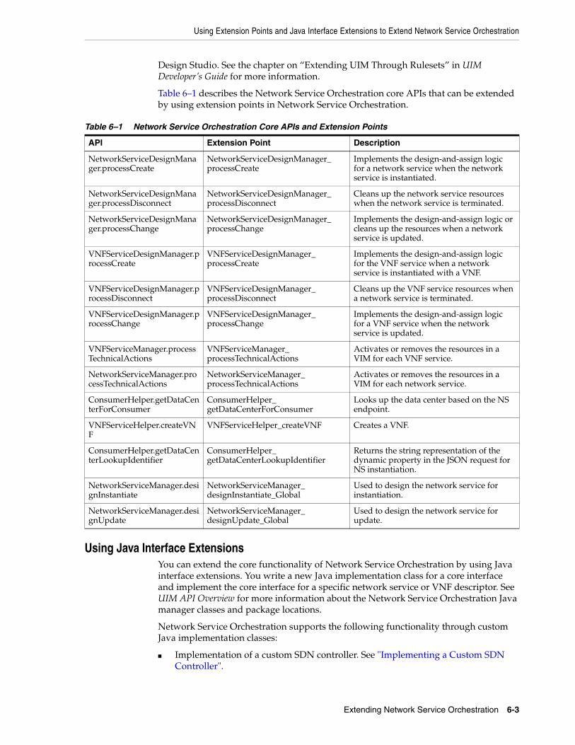
Using Extension Points and Java Interface Extensions to Extend Network Service Orchestration
Extending Network Service Orchestration 6-3
Design Studio. See the chapter on “Extending UIM Through Rulesets” in UIM Developer’s Guide for more information.
Table 6–1 describes the Network Service Orchestration core APIs that can be extended by using extension points in Network Service Orchestration.
Using Java Interface ExtensionsYou can extend the core functionality of Network Service Orchestration by using Java interface extensions. You write a new Java implementation class for a core interface and implement the core interface for a specific network service or VNF descriptor. See UIM API Overview for more information about the Network Service Orchestration Java manager classes and package locations.
Network Service Orchestration supports the following functionality through custom Java implementation classes:
■ Implementation of a custom SDN controller. See "Implementing a Custom SDN Controller".
Table 6–1 Network Service Orchestration Core APIs and Extension Points
API Extension Point Description
NetworkServiceDesignManager.processCreate
NetworkServiceDesignManager_processCreate
Implements the design-and-assign logic for a network service when the network service is instantiated.
NetworkServiceDesignManager.processDisconnect
NetworkServiceDesignManager_processDisconnect
Cleans up the network service resources when the network service is terminated.
NetworkServiceDesignManager.processChange
NetworkServiceDesignManager_processChange
Implements the design-and-assign logic or cleans up the resources when a network service is updated.
VNFServiceDesignManager.processCreate
VNFServiceDesignManager_processCreate
Implements the design-and-assign logic for the VNF service when a network service is instantiated with a VNF.
VNFServiceDesignManager.processDisconnect
VNFServiceDesignManager_processDisconnect
Cleans up the VNF service resources when a network service is terminated.
VNFServiceDesignManager.processChange
VNFServiceDesignManager_processChange
Implements the design-and-assign logic for a VNF service when the network service is updated.
VNFServiceManager.processTechnicalActions
VNFServiceManager_processTechnicalActions
Activates or removes the resources in a VIM for each VNF service.
NetworkServiceManager.processTechnicalActions
NetworkServiceManager_processTechnicalActions
Activates or removes the resources in a VIM for each network service.
ConsumerHelper.getDataCenterForConsumer
ConsumerHelper_getDataCenterForConsumer
Looks up the data center based on the NS endpoint.
VNFServiceHelper.createVNF
VNFServiceHelper_createVNF Creates a VNF.
ConsumerHelper.getDataCenterLookupIdentifier
ConsumerHelper_getDataCenterLookupIdentifier
Returns the string representation of the dynamic property in the JSON request for NS instantiation.
NetworkServiceManager.designInstantiate
NetworkServiceManager_designInstantiate_Global
Used to design the network service for instantiation.
NetworkServiceManager.designUpdate
NetworkServiceManager_designUpdate_Global
Used to design the network service for update.

Using Extension Points and Java Interface Extensions to Extend Network Service Orchestration
6-4 Network Service Orchestration Implementation Guide
■ Implementation of a custom VNF monitoring engine. See "Implementing a Custom Monitoring Engine".
■ Implementation of a custom VIM. See "Implementing a Custom VIM".
■ Implementation of a custom VNF life cycle manager. See "Implementing a Custom VNF Life Cycle Manager".
■ Implementation of an adapter for a custom VNF manager. See "Implementing an Adapter for a Custom VNF Manager".
■ Implementation of a custom VNF connection manager. See "Implementing a Custom VNF Connection Manager".
■ Implementation of a custom VNF configuration manager. See "Implementing a Custom VNF Configuration Manager".
■ Implementation of a custom response manager. See "Implementing a Custom Response Manager".
■ Implementation of a custom notification manager. See "Implementing a Custom Notification Manager".
Implementing a Custom SDN ControllerBy default, Network Service Orchestration supports OpenStack Neutron Networking-SFC (Service Function Chaining) for service chaining, but you can also implement a custom SDN controller.
You can implement a custom SDN controller in one of the following ways:
■ Using a custom SDN driver in Openstack Networking-SFC. Network Service Orchestration supports VNF forwarding graph (VNFFG) implementation using Openstack Networking-SFC. OpenStack Neutron Networking-SFC can interface with different SDN drivers in the southbound integration. To use a different SDN Controller, you must configure the required driver in OpenStack Neutron. Refer to the OpenStack documentation for more information.
■ Creating a Java implementation class for the SDN Controller interface. See "Implementing a Custom SDN Controller by Creating a Java Implementation Class" for more information.
Implementing a Custom SDN Controller by Creating a Java Implementation ClassTo implement a custom SDN controller by creating a Java implementation class:
1. In the custom Network Service descriptor cartridge project, create a Java implementation class for the SDN controller.
2. Configure the custom SDN controller class to implement the oracle.communications.inventory.nso.nfvi.SDNController interface, which is available in UIM_SDK/lib/nso-managers.jar.
3. Override the following methods in the custom SDN controller Java implementation class:
public String createClassifier(Map request) throws Exception
Note: Implementing some custom managers requires changes to the nso.properties file. Make a backup copy of the file before modifying it.

Using Extension Points and Java Interface Extensions to Extend Network Service Orchestration
Extending Network Service Orchestration 6-5
public String deleteClassifier(Map request) throws Exceptionpublic String createNFP(Map request) throws Exceptionpublic String deleteNFP(Map request) throws Exceptionpublic String updateNFP(Map request) throws Exceptionpublic String customCall(Map request) throws Exception
4. In your Network Service descriptor cartridge project, create or update the network service properties file and add the following entry:
sdnController.NSD_Name=SDNController_ImplementationClassPath
where:
■ NSD_Name is the name of the network service descriptor
■ SDNController_ImplementationClassPath is the path of the implementation class of your custom SDN controller
5. Build and redeploy the cartridge.
Figure 6–1 shows a model diagram that depicts the relationship between the Java Manager interface for the SDN Controller and your new custom Java implementation class.
Figure 6–1 Custom SDN Controller Model

Using Extension Points and Java Interface Extensions to Extend Network Service Orchestration
6-6 Network Service Orchestration Implementation Guide
Implementing a Custom Monitoring EngineBy default, Network Service Orchestration supports integration with OpenStack Ceilometer, but you can also implement and use a custom monitoring engine.
Figure 6–2 shows a model diagram that depicts the relationship between the Java Manager interface for the Monitoring Manager and your new custom Java implementation class.
Figure 6–2 Custom Monitoring Engine Model
To implement a custom monitoring engine:
1. In the custom VNF descriptor cartridge project, create a Java implementation class for the VNF monitoring manager.
2. Configure the VNFMonitoringManager class to implement the oracle.communications.inventory.nso.nfvi.VNFMonitoringManager interface, which is available in UIM_SDK/lib/nso-managers.jar.
3. Override the following methods in the custom VNF monitoring engine Java implementation class:
public String createAlarms(Map request) throws Exceptionpublic String deleteAlarms(Map request) throws Exceptionpublic String updateAlarms(Map request) throws Exceptionpublic String getAlarms(Map request) throws Exceptionpublic String customCall(Map request) throws Exception
4. In the VNF descriptor cartridge project, create or update the VNF properties file and add the following entry:
vnfMonitor.VNFD_Name=MonitoringEngine_ImplementationClassPath
Note: If the sdnController.NSD_Name entry is commented out or if the path of the implementation class is not specified, Network Service Orchestration does not perform the network flow operations such as creation of flows, deletion of flows, and update of flows for the network service.

Using Extension Points and Java Interface Extensions to Extend Network Service Orchestration
Extending Network Service Orchestration 6-7
where:
■ VNFD_Name is the name of the VNF descriptor
■ MonitoringEngine_ImplementationClassPath is the path of the implementation class of your monitoring engine
5. Build and redeploy the cartridge.
Implementing a Custom VIMBy default, Network Service Orchestration supports integration with OpenStack, but you can also implement a custom VIM.
Figure 6–3 shows a model diagram that depicts the relationship between the Java Manager interface for the VIM and your new custom Java implementation class.
Figure 6–3 Custom VIM Model
Note: If the vnfMonitor.VNFD_Name entry is commented out or if the path of the implementation class is not specified, Network Service Orchestration does not perform monitoring operations such as creation, deletion, and update of alarms for the network service.

Using Extension Points and Java Interface Extensions to Extend Network Service Orchestration
6-8 Network Service Orchestration Implementation Guide
To implement a custom VIM:
1. In your custom cartridge project, create a Java implementation class for the NFVIManager interface.
2. Configure the NFVIManager class to implement the oracle.communications.inventory.nso.nfvi.NFVIManager interface, which is available in UIM_SDK/lib/nso-managers.jar.
3. Override the methods in the custom NFVI manager Java implementation class.
4. Open the UIM_Home/config/nso.properties file, and add or update the following entry:
nfviMgr.nfviType=VIM_ImplementationClassPath
where:
■ nfviType is the type of VIM. For example, OpenStack.
■ VIM_ImplementationClassPath is the path of the implementation class of your VIM
5. Build and redeploy the cartridge.
Implementing a Custom VNF Life Cycle ManagerBy default, Network Service Orchestration manages VNF life cycle operations (such as instantiate, reboot, and terminate) by using OpenStack Compute services (referred to as Nova), but you can also implement and use a custom VNF life cycle manager with Network Service Orchestration.
Figure 6–4 shows a model diagram that depicts the relationship between the Java Manager interface for the Life Cycle Manager and your new custom Java implementation class.

Using Extension Points and Java Interface Extensions to Extend Network Service Orchestration
Extending Network Service Orchestration 6-9
Figure 6–4 Custom VNF Life Cycle Manager Model
To implement a custom VNF life cycle manager:
1. In your custom cartridge project, create a Java implementation class for the VNF life cycle manager.
2. Configure the custom VNF life cycle manager class to implement the oracle.communications.inventory.nso.nfvi.VNFLifeCycleManager interface, which is available in UIM_SDK/lib/nso-managers.jar.
3. Override the methods in the custom VNF life cycle manager Java implementation class.
4. Open the UIM_Home/config/nso.properties file, and add or update the following entry:
vnflcMgr.vimType=VNFLifecycleManager_ImplementationClassPath
where:
■ vimType is the type of VIM
■ VNFLifecycleManager_ImplementationClassPath is the path of the implementation class of your custom VNF life cycle manager
5. Build and redeploy the cartridge.
Implementing an Adapter for a Custom VNF ManagerBy default, Network Service Orchestration contains and uses the built-in adapter for the built-in VNF manager to manage the VNFs in your network services, but you can also implement an adapter to integrate with third-party VNF managers.

Using Extension Points and Java Interface Extensions to Extend Network Service Orchestration
6-10 Network Service Orchestration Implementation Guide
Figure 6–5 shows a model diagram that depicts the relationship between the Java Manager interface for the VNF Manager and your new custom Java implementation class.
Figure 6–5 Custom Adapter for VNF Manager Model
To implement an adapter for custom VNF manager:
1. In your custom cartridge project, create a Java implementation class for the custom adapter.
2. Configure the custom adapter class to implement the oracle.communications.inventory.nso.api.sb.SBSystemManager interface, which is available in UIM_SDK/lib/nso-managers.jar.
3. Override the methods in the custom adapter Java implementation class:
4. Open the UIM_Home/config/nso.properties file, and add or update the following entry:
sbClient.name=vnf_manager_adapter_ImplementationClassPath
where:
■ name is the name of the VNF descriptor
■ vnf_manager adapter_ImplementationClassPath is the path of the implementation class of your custom
5. Build and redeploy the cartridge.
Implementing a Custom VNF Connection ManagerNetwork Service Orchestration includes a VNF connection manager that enables Network Service Orchestration to establish a communication channel with VNFs for deploying configurations during VNF life cycle operations. You can also implement a custom VNF connection manager for Network Service Orchestration by writing an extension.

Using Extension Points and Java Interface Extensions to Extend Network Service Orchestration
Extending Network Service Orchestration 6-11
Figure 6–6 shows a model diagram that depicts the relationship between the Java Manager interface for the VNF Connection Manager and your new custom Java implementation class.
Figure 6–6 Custom VNF Connection Manager Model
To implement a custom VNF connection manager:
1. In the custom VNF descriptor cartridge project, create a Java implementation class for the custom VNF connection manager.
2. Configure the custom VNF connection manager class to implement the oracle.communications.inventory.nso.nfvi.VNFConnectionManager interface, which is available in UIM_SDK/lib/nso-managers.jar.
3. Override the methods in the custom VNF connection manager Java implementation class.
4. In the VNF descriptor cartridge project, create or update the VNF properties file and add the following entry:
vnfConnectionMgr.VNFD_Name=VNFConnectionManager_ImplementationClassPath
where:
■ VNFD_Name is the name of the VNF descriptor
■ VNFConnectionManager_ImplementationClassPath is the path of the implementation class of your custom VNF connection manager
5. Build and redeploy the cartridge.
Note: If the vnfConnectionMgr.VNFD_Name key is commented out or if the path of the implementation class is not specified, Network Service Orchestration does not run configurations on the virtual machines on which the VNFs are deployed.

Using Extension Points and Java Interface Extensions to Extend Network Service Orchestration
6-12 Network Service Orchestration Implementation Guide
Implementing a Custom VNF Configuration ManagerNetwork Service Orchestration includes a VNF configuration manager that generates configuration content for VNF configuration. You can also implement a custom VNF configuration manager for Network Service Orchestration by writing an extension.
Figure 6–7 shows a model diagram that depicts the relationship between the Java Manager interface for the VNF Configuration Manager and your new custom Java implementation class.
Figure 6–7 Custom VNF Configuration Manager Model
To implement a custom VNF configuration manager:
1. In the custom VNF descriptor cartridge project, create a Java implementation class for the custom VNF configuration manager.
2. Configure the custom VNF configuration manager class to implement the oracle.communications.inventory.nso.nfvi.VNFConfigManager interface, which is available in UIM_SDK/lib/nso-managers.jar.
3. Override the methods in the custom VNF configuration manager Java implementation class.
4. In the VNF descriptor cartridge project, create or update the VNF properties file and add the following entry:
vnfConfigMgr.VNFD_Name=VNFConfigurationManager_ImplementationClassPath
where:
■ VNFD_Name is the name of the VNF descriptor
■ VNFConfigurationManager_ImplementationClassPath is the path of the implementation class of your custom VNF configuration manager
5. Build and redeploy the cartridge.
Note: If the vnfConfigMgr.VNFD_Name entry is commented out or if the path of the implementation class is not specified, Network Service Orchestration does not generate configurations for the VNF.
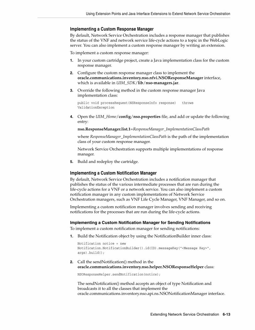
Using Extension Points and Java Interface Extensions to Extend Network Service Orchestration
Extending Network Service Orchestration 6-13
Implementing a Custom Response ManagerBy default, Network Service Orchestration includes a response manager that publishes the status of the VNF and network service life-cycle actions to a topic in the WebLogic server. You can also implement a custom response manager by writing an extension.
To implement a custom response manager:
1. In your custom cartridge project, create a Java implementation class for the custom response manager.
2. Configure the custom response manager class to implement the oracle.communications.inventory.nso.nfvi.NSOResponseManager interface, which is available in UIM_SDK/lib/nso-managers.jar.
3. Override the following method in the custom response manager Java implementation class:
public void processRequest(NSResponseInfo response) throws ValidationException
4. Open the UIM_Home/config/nso.properties file, and add or update the following entry:
nso.ResponseManager.list.1=ResponseManager_ImplementationClassPath
where ResponseManager_ImplementationClassPath is the path of the implementation class of your custom response manager.
Network Service Orchestration supports multiple implementations of response manager.
5. Build and redeploy the cartridge.
Implementing a Custom Notification Manager By default, Network Service Orchestration includes a notification manager that publishes the status of the various intermediate processes that are run during the life-cycle actions for a VNF or a network service. You can also implement a custom notification manager in any custom implementations of Network Service Orchestration managers, such as VNF Life Cycle Manager, VNF Manager, and so on.
Implementing a custom notification manager involves sending and receiving notifications for the processes that are run during the life-cycle actions.
Implementing a Custom Notification Manager for Sending NotificationsTo implement a custom notification manager for sending notifications:
1. Build the Notification object by using the NotificationBuilder inner class:
Notification notice = new Notification.NotificationBuilder().id(ID).messageKey("<Message Key>", args).build();
2. Call the sendNotification() method in the oracle.communications.inventory.nso.helper.NSOResponseHelper class:
NSOResponseHelper.sendNotification(notice);
The sendNotification() method accepts an object of type Notification and broadcasts it to all the classes that implement the oracle.communications.inventory.nso.api.ns.NSONotificationManager interface.

Localizing Network Service Orchestration
6-14 Network Service Orchestration Implementation Guide
Implementing a Custom Notification Manager for Receiving NotificationsTo implement a custom response manager for receiving notifications:
1. In your custom cartridge project, create a Java implementation class for the custom notification manager by implementing the oracle.communications.inventory.nso.api.ns.NSONotificationManager interface, which is available in UIM_SDK/lib/nso-managers.jar.
2. Override the following method in the custom notification manager Java implementation class:
public void processNotification(Notification notification)
3. Open the UIM_Home/config/nso.properties file, and add or update the following entry:
nso.NotificationAgent.list.1=NotificationManager_ImplementationClassPath
where NotificationManager_ImplementationClassPath is the path of the implementation class of your custom notification manager.
Network Service Orchestration supports multiple implementations of notification manager.
4. Build and redeploy the cartridge.
Localizing Network Service OrchestrationYou can localize the UIM user interface, UIM Help, and the responses that the REST APIs return into your local language.
To localize Network Service Orchestration:
1. Localize the UIM user interface and UIM Help. For instructions, see the chapter about localizing UIM in UIM Developer’s Guide.
2. Localize the responses that the RESTful APIs return. See "Localizing the Responses in RESTful APIs" for instructions.
Localizing the Responses in RESTful APIsTo localize the responses in the Network Service Orchestration RESTful APIs:
1. Make a copy of the UIM_Home/config/resources/logging/nsoresourcebundle.properties file in the same directory and rename it as nsoresourcebundle_localeID.properties, where localeID is the locale ID of your local language. For example, rename it to nsoresourcebundle_fr_FR.properties to localize the responses into French.
2. Open the nsoresourcebundle_localeID.properties file and localize the messages.
3. (Optional) If you want to implement the sample Network Protection service by using the sample cartridges, make a copy of the UIM_Home/config/resources/logging/npassresourcebundle.properties file in the same directory and name it as npaasresourcebundle_localeID.properties and localize the messages.
4. Restart the UIM server.
5. In your RESTful API client, update the Accept-Language header with the locale ID. For example, for French, specify fr-FR.

7
Network Service Orchestration RESTful API Reference 7-1
7Network Service Orchestration RESTful APIReference
This chapter provides reference information about the Oracle Communications Network Service Orchestration RESTful API resources.
About the Network Service Orchestration RESTful APIsThe Network Service Orchestration RESTful API requests provide the northbound interface to Network Service Orchestration. Operation support systems (OSS) and VNF managers query the resource inventory for data.
The RESTful API requests enable you to perform various functions by using a RESTful API client.
The root URL for the Network Service Orchestration RESTful API resources is:
■ HTTP connection: http://nso_host:port/ocnso/1.1
■ SSL connection: https://nso_host:ssl_port/ocnso/1.1
where:
– nso_host is the name of the host on which Oracle Communications Unified Inventory Management (UIM) is installed
– port is the port number of the machine on which UIM is installed
– ssl_port is the SSL port number of the machine on which UIM is installed
To access the Network Service Orchestration RESTful API resources, in your RESTful API client, choose Basic Authentication and specify the user name and password of the machine on which UIM is installed.
The ora_nso_webservices.war file is included in the inventory.ear file and is deployed once the UIM installation is complete.
Note: If you use HTTPS-enabled OpenStack Keystone RESTful APIs, add the Certified Authority certificate to the TrustStore that your application server uses. If OpenStack Keystone is configured with self-signed certificate, then add the self-signed certificate to the TrustStore of the application server. See the Oracle WebLogic Server documentation for information about configuring the TrustStore.

Network Service Orchestration RESTful API Resources
7-2 Network Service Orchestration Implementation Guide
Network Service Orchestration RESTful API ResourcesTable 7–1 lists the Network Service Orchestration RESTful API requests provided, along with the method, resource and description for each. This table is ordered first by entity and then by the method in the order of POST, PUT, GET and DELETE.
Table 7–1 Network Service Orchestration RESTful API Resources
Request Method Resource Description
Register VIM POST /ocnso/1.1/vim Registers the IP address, port, user name and password of the Virtual Infrastructure Manager (VIM) with Network Service Orchestration.
Discover VIM Resources POST /ocnso/1.1/vim/vimId/discovery?infoLevel=vim_information
Discovers the resources of the registered VIM and adds them to inventory.
Update VIM PUT /ocnso/1.1/vim/vimId Updates the attributes (for example IP address, port, user name, password, and project name) of an existing VIM in Network Service Orchestration.
Get VIM Details GET /ocnso/1.1/vim/vimId Returns information about a VIM that is registered with Network Service Orchestration.
Instantiate Network Service POST /ocnso/1.1/ns Instantiates a network service and its constituent Virtual Network Functions (VNFs).
Get Network Services GET /ocnso/1.1/ns/nsdName=nsdName
Returns a list of all active network services that are created based on the given network service descriptor.
Get Network Service Details GET /ocnso/1.1/ns/networkServiceId
Returns details about a network service.
Get Network Service VNFs GET /ocnso/1.1/ns/networkServiceId/vnfs
Returns details about VNFs in a network service.
Get Network Service Networks GET /ocnso/1.1/ns/networkServiceId/networks
Returns details about networks in a network service.
Get Network Service End Points
GET /ocnso/1.1/ns/networkServiceId/endpoints
Returns details about endpoints in a network service.
Get Network Service Status GET /ocnso/1.1/ns/networkServiceId/status
Returns status information of a network service.
Terminate Network Service DELETE /ocnso/1.1/ns/networkServiceId
Terminates a network service and the constituent VNFs.
Add VNF to Network Service POST /ocnso/1.1/ns/networkServiceId/vnfs
Adds VNFs to a network service.
Terminate VNF in a Network Service
DELETE /ocnso/1.1/ns/networkServiceId/vnfs
Terminates a VNF in a network service.
Heal VNF POST /ocnso/1.1/vnf/vnfId/heal?action=action
Heals a VNF by either rebooting or replacing all the virtual machines on which the VDUs of the VNF are deployed.
Available values for the action parameter are:
■ replace
■ reboot
Scale VNF POST /ocnso/1.1/ns/networkServiceId/scale/vnfId
Scales a VNF in a network service by either adding new instances or removing existing instances of the constituent VDUs of the VNF.
Get VNF Details GET /ocnso/1.1/vnf/vnfId Returns details about a VNF.
Get VNF Status GET /ocnso/1.1/vnf/vnfId/status Returns status information about a VNF.
Heal VDU POST /ocnso/1.1/vnf/vnfId/vdus/vduId/heal
Heals a VDU by rebooting the virtual machine on which the VDU is deployed.
Register PNF POST /ocnso/1.1/pnfs Registers or creates a Physical Network Function (PNF) in inventory.

RESTful API Responses
Network Service Orchestration RESTful API Reference 7-3
RESTful API ResponsesThis section describes the fields and possible values for the responses returned from Network Service Orchestration RESTful API calls.
Table 7–2 describes the fields that are contained in a response.
Update PNF PUT /ocnso/1.1/pnfs/pnfId Updates an existing registered PNF.
Get PNFs GET /ocnso/1.1/pnfs?descriptorName=pnfdName
Returns the list of PNFs given the input descriptor name.
Get PNF Details GET /ocnso/1.1/pnfs/pnfId Returns the PNF details given the input PNF identifier.
Unregister PNF DELETE /ocnso/1.1/pnfs/pnfId Unregisters an existing PNF.
Register EMS POST /ocnso/1.1/ems Registers or creates an Element Management System (EMS) in inventory.
Update EMS PUT /ocnso/1.1/ems/emsId Updates an existing registered EMS.
Get EMSs GET /ocnso/1.1/ems?descriptorName=emsdName
Returns the list of EMSs given the input descriptor name.
Get EMS Details GET /ocnso/1.1/ems/emsId Returns the EMS details given the input EMS identifier.
Unregister EMS DELETE /ocnso/1.1/ems/emsId Unregisters an existing EMS.
Get Network Service Descriptors
GET /ocnso/1.1/nsd Returns a list of all network service descriptors that are deployed in Network Service Orchestration.
Get Network Service Descriptor Details
GET /ocnso/1.1/nsd/nsdName Returns details about a network service descriptor.
Get Network Service Descriptor VNFDs
GET /ocnso/1.1/nsd/nsdName/vnfds
Returns a list of VNF descriptors in a network service descriptor.
Get Network Service Descriptor Flavors
GET /ocnso/1.1/nsd/nsdName/flavors
Returns a list of all constituent service flavors that are defined for a network service descriptor.
Get VNF Descriptor Details GET /ocnso/1.1/vnfd/vnfdName Returns details about a VNF descriptor.
Get VNF Descriptor Flavors GET /ocnso/1.1/vnfd/vnfdName/flavors
Returns a list of deployment flavors that are defined for a VNF descriptor.
Table 7–2 Fields in the Response
Response Field Description
status This field contains the status of the request processing. The following are the valid values:
■ SUCCESS
■ ACCEPTED
■ FAILURE
code This field contains the HTTP status code value. Table 7–3 describes the possible values.
message This optional field contains a high-level error message and is present only for a failed request.
data This optional field contains the response information from the request and it only exists for successful requests. This field may not be relevant to all requests.
Table 7–1 (Cont.) Network Service Orchestration RESTful API Resources
Request Method Resource Description

RESTful API Responses
7-4 Network Service Orchestration Implementation Guide
Example 7–1 shows a success response for a network service instantiation request. The data portion contains the operation-specific information and message about the successful request.
Example 7–1 Sample Response Snippet on Success
{ "status": "SUCCESS", "code": "202", "message": "[INV-430902] Network Service instantiation is in progress.", "data": { "id": "1125001", "descriptorName": "NPaas", "name": "NSO_NPassService_1", "status": "PENDING", "businessInteractionId": "1275003", "businessInteractionStatus": "IN_PROGRESS" . . . }}
Example 7–2 shows a response to a failed request.
Example 7–2 Sample Response on Failure
{ "status": "FAILURE", "code": "500", "message": "No Network service exists with provided Network Service id 100.", "errors": [], "exception": { "code": "INV-430355", "message": "No Network service exists with provided Network Service id 100." }}
Table 7–3 describes the HTTP response status codes for the RESTful API resources.
exception This optional field contains information when an exception occurs for a failed request.
errors This optional field contains an array of information when an error occurs for a failed request.
warnings This optional field contains an array of information when a warning occurs for a failed request.
Table 7–2 (Cont.) Fields in the Response
Response Field Description

Sample Requests and Responses
Network Service Orchestration RESTful API Reference 7-5
Sample Requests and ResponsesThe following sections provide sample JSON requests and responses for the Network Service Orchestration RESTful API resources.
Register VIMRegisters details about the VIM with Network Service Orchestration such as the following:
■ Host IP address
■ Port
■ User name
■ Password
This resource results in the creation of a VIM.
MethodPOST
URLhttp://nso_host:port/ocnso/1.1/vim
Sample Request{ "id": "Vim1", "name": "Vim1", "host": "192.0.2.251", "port": "12345", "userName": "nso", "pswd": "password",
Table 7–3 HTTP Response Status Codes for the RESTful API Resources
Response Code Description
200 OK The request is successful.
The information returned in the response depends on the method used in the request. For example:
■ GET returns one or more entities corresponding to the requested resource.
■ POST returns an entity describing or containing the result of the action.
202 Accepted The request has been accepted for processing, but processing has not yet started.
The request might or might not eventually be acted upon; it might be disallowed when the request is processed.
400 Bad Request The request could not be understood by the server due to incorrect syntax. Correct the syntax before repeating the request.
401 Unauthorized The request could not be authorized by the server due to invalid authentication or the absence of a valid user name and password. All requests require valid user authentication. See "About the Network Service Orchestration RESTful APIs" for more information.
404 Not Found The server has not found a matching request or URI.
500 Internal Server Error
The server encountered an unexpected condition that prevented it from fulfilling the request.

Sample Requests and Responses
7-6 Network Service Orchestration Implementation Guide
"projectName": "test", "domainName": "default", "version": "3", "sslEnabled": "false", "type": "OpenStack", "cpuOvercommitRatio": "15", "memoryOvercommitRatio": "1.5", "diskOvercommitRatio": "1.0"}
Sample Response{ "status": "SUCCESS", "code": "200", "message": "[INV-430914] Vim1 is successfully registered with NSO."}
Discover VIM ResourcesDiscovers the resources that are available on the VIM. For example, it creates the following resources as custom objects:
■ Availability zones
■ Flavors
■ Hosts
■ Virtual Data Center (VDC)
MethodPOST
URLhttp://nso_host:port/ocnso/1.1/vim/vimId/discovery?infoLevel=vimInformation
where:
■ vimId is the identifier of the VIM whose resources you want to discover
■ vimInformation is the level of information about the VIM that you want to receive in the response. The values for infoLevel are:
– summary: Include a summary of the VIM resources.
– details: Include complete details about all the VIM resources.
Sample RequestThis API does not require any request parameters.
Sample ResponseThis is a sample response when the infoLevel parameter in the URL is set to summary:
{ "status": "SUCCESS", "code": "200", "data": { "summary": { "Number of Flavors": 26,

Sample Requests and Responses
Network Service Orchestration RESTful API Reference 7-7
"Number of Zones": 3 "Number of Hosts": 4, "Number of Networks": 80, "Number of Subnets": 80, } }}
The following is a sample response when the infoLevel parameter in the URL is set to details:
{ "data": { "availabilityZones": [ { "zone": "CustomerTermination", "hosts": [ "compute2" ] }, { "zone": "nova", "hosts": [ "compute4" ] } ], "networks": [ { "network": "ext-net", "subnets": [ "ext-subnet" ] }, { "network": "QANetwork", "subnets": [ "QASubnet" ] } ], "flavors": [ "m1.tiny", "m1.small", "m1.large" ] }}
Update VIMUpdates details about an existing VIM in Network Service Orchestration. For example, you can update the following attributes:
■ Host IP address
■ Port
■ User name
■ Password

Sample Requests and Responses
7-8 Network Service Orchestration Implementation Guide
■ Project name
The update persists the new attribute values to the inventory database.
MethodPUT
URLhttp://nso_host:port/ocnso/1.1/vim/vimId
where vimId is the identifier of the VIM that you want to update.
Sample Request{ "host": "192.0.2.252", "port": "12345", "userName": "nso", "pswd": "password", "projectName": "test", "domainName": "default", "version": "3", "sslEnabled": "false", "type": "OpenStack", "cpuOvercommitRatio": "15", "memoryOvercommitRatio": "1.5", "diskOvercommitRatio": "1.0"}
Sample Response{ "status": "SUCCESS", "code": "200", "message": "[INV-430921] VIM updated successfully."}
Get VIM DetailsRetrieves the details of a VIM that is registered in inventory.
MethodGET
URLhttp://nso_host:port/ocnso/1.1/vim/vimId
where vimId is the identifier of the VIM.
Sample Response{ "status": "SUCCESS", "code": "200", "data": { "id": "Vim1", "name": "Vim1", "host": "192.0.2.249", "port": "12345", "userName": "admin",

Sample Requests and Responses
Network Service Orchestration RESTful API Reference 7-9
"pswd": "****", "projectName": "admin", "domainName": "default", "type": "OpenStack", "version": "3", "sslEnabled": false, "cpuOvercommitRatio": "15", "memoryOvercommitRatio": "1.5", "diskOvercommitRatio": "1.0" }}
Instantiate Network ServiceCreates a network service, the related resources, and starts the resources in the network service. This resource can optionally include VNFFGs, VNFs, and PNFs.
MethodPOST
URLhttp://nso_host:port/ocnso/1.1/ns
Sample Request{ "name":"NPaaS_A", "descriptorName":"NPaaS", "flavorName":"Juniper", "vnffgs": [ "data-vnffg" ], "vnfs":[ { "name":"VNF_A", "descriptorName":"Juniper_vSRX", "flavorName":"standard", "version":"1.0" } ], "pnfs": [ { "id": "39", "descriptorName": "Cisco_xRV" } ], "endPoints": [ { "name": "Service-EP1", "reference":"Service_EP1", "parameters": [ { "name": "IPAddress", "value": "192.0.2.251" }, { "name": "externalNet", "value": "ext1" },

Sample Requests and Responses
7-10 Network Service Orchestration Implementation Guide
{ "name": "serviceLocation", "value": "SanFransisco" } ] }, { "name": "Service-EP2", "reference":"Service_EP2", "parameters": [ { "name": "IPAddress", "value": "192.0.2.252" }, { "name": "externalNet", "value": "ext1" }, { "name": "serviceLocation", "value": "SanFransisco" } ] } ]}
The following list indicates which request parameters are mandatory and which are optional:
■ The name, descriptorName, and flavorName parameters for the network service are mandatory.
■ The vnffgs request parameter is optional. Ensure that the ID of the VNFFG is same as the ID that you specified in the <vnffg> element of the network service descriptor XML file.
The VNFFG that you specify in the vnffgs request parameter overrides any default VNFFG you specified in the network service descriptor file. If you want to instantiate the network service with the default VNFFG, you must either leave the vnffgs request parameter blank or specify the same ID that you specified for the default VNFFG in the <vnffg> element of the network service descriptor file.
If you want the network service to have an additional VNFFG beside the default VNFFG, you must specify both the VNFFGs separately within the vnffgs parameter in the network service instantiation request.
■ The vnfs request parameter is optional. Specify the VNF name if you want to name the VNF.
■ The pnfs request parameter is optional. Specify the information about PNFs if your network service contains PNFs.
■ The endPoints request parameter is mandatory because a network service should have at least one endpoint to determine the best suitable data center for the network service. If your network service contains forwarding graphs, specify the information about service endpoints.
Sample Response{ "status": "SUCCESS",

Sample Requests and Responses
Network Service Orchestration RESTful API Reference 7-11
"code": "202", "message": "[INV-430902] Network Service instantiation is in progress.", "data": { "id": "39", "name": "NPaaS_A", "descriptorName": "NPaaS", "status": "PENDING", "businessInteractionId": "83", "businessInteractionStatus": "IN_PROGRESS", "serviceDeploymentFlavorName": "Juniper", "vimId": "ONAP21MitakaCloud2", "datacenterName": "ONAP21MitakaCloud2", "networks": [ { "name": "39_Data_OUT(ONAP21MitakaCloud2)", "id": "39_Data_OUT(ONAP21MitakaCloud2)", "status": "PENDING_REFERENCE", "subnets": [ { "startIP": "192.0.2.21", "prefix": "28" } ] }, { "name": "nfvo-poc3-mgmt(ONAP21MitakaCloud2)", "id": "nfvo-poc3-mgmt(ONAP21MitakaCloud2)", "externalId": "c64943a8-6717-4880-a46e-5b0d2a625a8c", "status": "PENDING_REFERENCE", "subnets": [ { "startIP": "192.0.2.22", "prefix": "24", "externalId": "6aa4a6cd-4c21-48e4-9f47-330a9e227046" } ] }, { "name": "39_Data_IN(ONAP21MitakaCloud2)", "id": "39_Data_IN(ONAP21MitakaCloud2)", "status": "PENDING_REFERENCE", "subnets": [ { "startIP": "192.0.2.23", "prefix": "27" } ] } ], "endpoints": [ { "id": "39", "name": "Service-EP1", "descriptorName": "NetworkServiceEndPoint", "status": "Pending Reference" }, { "id": "40", "name": "Service-EP2", "descriptorName": "NetworkServiceEndPoint",

Sample Requests and Responses
7-12 Network Service Orchestration Implementation Guide
"status": "Pending Reference" } ], "vnfs": [ { "id": "37", "name": "VNF_A", "status": "Pending Assign", "descriptorName": "Juniper_vSRX", "businessInteractionId": "84", "businessInteractionStatus": "IN_PROGRESS" } ], "pnfs": [ { "id": "39", "name": "PNF_A", "descriptorName": "Cisco_xRV", "ipAddress": "192.0.2.231", "userName": "user", "pswd": "****", "sslEnabled": false, "sshKey": "xxxxxxxxxxxxxxxxx", "parameters": [ {} ] } ], "forwardingGraphs": [ { "name": "data-vnffg", "nfps": [ { "name": "nfp1" } ] } ] }}
Get Network ServicesRetrieves the list of active network services that are related to the input network service descriptor.
MethodGET
URLhttp://nso_host:port/ocnso/1.1/ns?nsdName=nsdName&status=nsStatus
where:
■ nsdName is the name of the network service descriptor and
■ (Optional) nsStatus is the status of the network service. If you do not specify the status parameter, all the network services that are in In Service status are retrieved.

Sample Requests and Responses
Network Service Orchestration RESTful API Reference 7-13
■ You can retrieve the network services that are in the following statuses:
– Cancel Pending Disconnect
– Cancelled
– In Service
– Pending
– Pending Cancel
– Pending Disconnect
– Suspended
Sample ResponseThe following is the sample response when the status parameter in the URL is not set.
{ "status": "SUCCESS", "code": "200", "data": [ { "id": "1050001", "name": "NSO_NPassService_1", "descriptorName": "NPaaS", "status": "IN_SERVICE" }, { "id": "1050005", "name": "NSO_NPassService_2", "descriptorName": "NPaaS", "status": "IN_SERVICE" }, { "id": "1125001", "name": "NSO_NPassService_3", "descriptorName": "NPaaS", "status": "IN_SERVICE" } ]}
Get Network Service DetailsRetrieves the details of a network service.
MethodGET
URLhttp://nso_host:port/ocnso/1.1/ns/networkServiceId
where networkServiceId is the identifier of the network service whose details you want to retrieve.
Sample Response{ "status": "SUCCESS", "code": "200",

Sample Requests and Responses
7-14 Network Service Orchestration Implementation Guide
"data": { "id": "1500001", "name": "NS_A", "descriptorName": "NPaaS", "status": "IN_SERVICE", "businessInteractionId": "1500001", "businessInteractionStatus": "COMPLETED", "serviceDeploymentFlavorName": "Juniper", "vimId": "ONAP21MitakaCloud2", "datacenterName": "ONAP21MitakaCloud2", "networks": [ { "name": "1500001_Data_OUT(ONAP21MitakaCloud2)", "id": "1500001_Data_OUT(ONAP21MitakaCloud2)", "externalId": "ef68fda2-da9c-4b45-a9c2-f6add002278e", "status": "REFERENCED", "subnets": [ { "startIP": "192.0.2.25", "prefix": "30", "externalId": "81acf49b-f656-4d5b-83f5-208cb05212df" } ] }, { "name": "nfvo-poc3-mgmt(ONAP21MitakaCloud2)", "id": "nfvo-poc3-mgmt(ONAP21MitakaCloud2)", "externalId": "c64943a8-6717-4880-a46e-5b0d2a625a8c", "status": "REFERENCED", "subnets": [ { "startIP": "192.0.2.25", "prefix": "24", "externalId": "6aa4a6cd-4c21-48e4-9f47-330a9e227046" } ] }, { "name": "1500001_Data_IN(ONAP21MitakaCloud2)", "id": "1500001_Data_IN(ONAP21MitakaCloud2)", "externalId": "a200be4e-cf49-4a3d-91eb-abc4c6747134", "status": "REFERENCED", "subnets": [ { "startIP": "192.0.2.23", "prefix": "27", "externalId": "e0308cf2-d95e-4da6-bb70-f1d917b15924" } ] } ], "endpoints": [ { "id": "1500001", "name": "Service-EP1", "descriptorName": "NetworkServiceEndPoint", "status": "Referenced", "serviceLocation": "SanFransisco" }, {

Sample Requests and Responses
Network Service Orchestration RESTful API Reference 7-15
"id": "1500002", "name": "Service-EP2", "descriptorName": "NetworkServiceEndPoint", "status": "Referenced", "serviceLocation": "SanFransisco" } ], "vnfs": [ { "id": "1425001", "name": "A", "status": "Assigned", "descriptorName": "Juniper_vSRX", "version": "1.0", "businessInteractionId": "1500002", "businessInteractionStatus": "COMPLETED", "deploymentFlavor": "standard" } ], "forwardingGraphs": [ { "name": "data-vnffg", "nfps": [ { "id": "79baa1d6-397c-482b-80b6-4f7edeb23b88", "name": "nfp1" } ] } ], "policies": [ { "id": "premium", "name": "premium", "type": "traffic-classification", "ruleReferences": [ { "id": "rule1", "action": "nfp-ref-id:nfp1" } ] }, { "id": "standard", "name": "standard", "type": "traffic-classification", "ruleReferences": [ { "id": "rule1", "action": "nfp-ref-id:nfp1" } ] } ], "rules": [ { "id": "rule1", "name": "rule1", "type": "traffic-classification", "params": [

Sample Requests and Responses
7-16 Network Service Orchestration Implementation Guide
{ "name": "protocol", "value": "UDP" } ] } ] }}
Get Network Service VNFsRetrieves the details about the VNFs in a network service.
MethodGET
URLhttp://nso_host:port/ocnso/1.1/ns/networkServiceId/vnfs
where networkServiceId is the identifier of the network service for the VNFs.
Sample Response{ "status": "SUCCESS", "code": "200", "data": { "id": "1500031", "name": "NS_D2", "descriptorName": "NPaaS", "status": "DISCONNECTED", "vnfs": [ { "id": "1425031", "name": "D2", "status": "Unassigned", "descriptorName": "Juniper_vSRX", "serviceId": "1500032", "serviceName": "D2Juniper_vSRX_Service", "serviceStatus": "DISCONNECTED", "serviceDescriptorName": "Juniper_vSRX_Service", "version": "1.0", "externalId": "1425031", "businessInteractionId": "1500050", "businessInteractionStatus": "COMPLETED", "deploymentFlavor": "standard", "connectionPoints": [ { "id": "1425032-1", "name": "CP03", "ipAddress": { "address": "192.0.2.25", "network": "nfvo-poc3-mgmt(ONAP21MitakaCloud2)", "externalId": "92cdbd28-9fed-49a3-a45c-5678e7a9e6df" } }, { "id": "1425032-2",

Sample Requests and Responses
Network Service Orchestration RESTful API Reference 7-17
"name": "CP01", "ipAddress": { "address": "192.0.2.27", "network": "1500031_Data_IN(ONAP21MitakaCloud2)", "externalId": "2b5d7b6b-9b42-4587-98a0-979d4d25ca1d" } }, { "id": "1425032-3", "name": "CP02", "ipAddress": { "address": "192.0.2.23", "network": "1500031_Data_OUT(ONAP21MitakaCloud2)", "externalId": "6563445b-0eff-4b21-b721-e6d0010b7f2f" } } ], "vdus": [ { "id": "1425032", "name": "NS_D2_1425031_1425032", "status": "Unassigned", "descriptorName": "Juniper_vSRX_VDU", "imageName": "vsrx-12.1X47-D20.7-npaas-v0.3", "availabilityZoneName": "nova", "externalID": "0b9140aa-a857-4d4c-8975-2a46c2aad89e", "host": "83e39178aac9fb1af89bcf825bcd5e808d3de2d370b12b0653a3e966", "flavor": { "name": "vsrx.medium", "cpus": "2", "memory": "4096.0", "disk": "20.0" }, "vnfcs": [ { "connectionPoints": [ { "id": "1425032-1", "name": "CP03", "ipAddress": { "address": "192.0.2.12", "network": "nfvo-poc3-mgmt(ONAP21MitakaCloud2)", "externalId": "92cdbd28-9fed-49a3-a45c-5678e7a9e6df" } }, { "id": "1425032-2", "name": "CP01", "ipAddress": { "address": "192.0.2.14", "network": "1500031_Data_IN(ONAP21MitakaCloud2)", "externalId": "2b5d7b6b-9b42-4587-98a0-979d4d25ca1d" } }, { "id": "1425032-3", "name": "CP02", "ipAddress": { "address": "192.0.2.15", "network": "1500031_Data_OUT(ONAP21MitakaCloud2)",

Sample Requests and Responses
7-18 Network Service Orchestration Implementation Guide
"externalId": "6563445b-0eff-4b21-b721-e6d0010b7f2f" } } ] } ], "parameters": [ { "name": "imageVersion", "value": "1.0" }, { "name": "imageId", "value": "vsrx-v1.0" } ] } ] } ] }}
Get Network Service NetworksRetrieves the details about the networks within a network service.
MethodGET
URLhttp://nso_host:port/ocnso/1.1/ns/networkServiceId/networks
where networkServiceId is the identifier of the network service.
Sample Response{ "status": "SUCCESS", "code": "200", "data": { "id": "1575001", "name": "NSO_NetworkService", "descriptorName": "NPaaS", "status": "IN_SERVICE", "serviceDeploymentFlavorName": "Juniper", "vimId": "ONAP21MitakaCloud2", "datacenterName": "ONAP21MitakaCloud2", "networks": [ { "name": "1575001_Data_OUT(ONAP21MitakaCloud2)", "id": "1575001_Data_OUT(ONAP21MitakaCloud2)", "externalId": "87697297-2795-440d-bea8-a33c2ba2e20e", "status": "REFERENCED", "subnets": [ { "startIP": "192.0.2.12", "prefix": "30", "externalId": "fba5b8f2-06b8-4d1b-8011-7d6d2b020101"

Sample Requests and Responses
Network Service Orchestration RESTful API Reference 7-19
} ] }, { "name": "1575001_Data_IN(ONAP21MitakaCloud2)", "id": "1575001_Data_IN(ONAP21MitakaCloud2)", "externalId": "7b801c76-ab7e-4f1b-9328-80a898611120", "status": "REFERENCED", "subnets": [ { "startIP": "192.0.2.13", "prefix": "27", "externalId": "3115de7a-b1e4-475d-ae94-393cfc4d3df6" } ] }, { "name": "nfvo-poc3-mgmt(ONAP21MitakaCloud2)", "id": "nfvo-poc3-mgmt(ONAP21MitakaCloud2)", "externalId": "c64943a8-6717-4880-a46e-5b0d2a625a8c", "status": "REFERENCED", "subnets": [ { "startIP": "192.0.2.12", "prefix": "24", "externalId": "6aa4a6cd-4c21-48e4-9f47-330a9e227046" } ] } ] }}
Get Network Service End PointsRetrieves the details about the endpoints in a network service.
MethodGET
URLhttp://nso_host:port/ocnso/1.1/ns/networkServiceId/endpoints
where networkServiceId is the identifier of the network service.
Sample Response{ "status": "SUCCESS", "code": "200", "data": { "id": "22", "name": "NPaaS_Service", "descriptorName": "NPaas", "status": "IN_SERVICE", "endpoints": [ { "id": "14", "name": "NSO_SGPcnsmr2",

Sample Requests and Responses
7-20 Network Service Orchestration Implementation Guide
"descriptorName": "NetworkServiceEndPoint", "ipAddress": "192.0.2.218", "status": "Referenced", "serviceLocation": "MTRLPQ03" } ] }}
Get Network Service StatusRetrieves the status information for a network service.
MethodGET
URLhttp://nso_host:port/ocnso/1.1/ns/networkServiceId/status
where networkServiceId is the identifier of the network service whose status information you want to retrieve.
Sample Response{ "status": "SUCCESS", "code": "200", "data": { "id": "22", "name": "Sample NS", "descriptorName": "NPaas", "status": "IN_SERVICE", "businessInteractionId": "47", "businessInteractionStatus": "COMPLETED", "networks": [ { "name": "22_Data_OUT(ONAP21)", "status": "REFERENCED" }, { "name": "22_Data_IN(ONAP21)", "status": "REFERENCED" }, { "name": "nfvo-poc3-mgmt(ONAP21)", "status": "REFERENCED" } ], "endpoints": [ { "id": "14", "name": "NSO_smr2", "descriptorName": "NetworkServiceEndPoint", "status": "Referenced" } ], "vnfs": [ { "id": "6",

Sample Requests and Responses
Network Service Orchestration RESTful API Reference 7-21
"name": "VNF-1_06", "status": "Assigned", "descriptorName": "Juniper_vSRX", } ] }}
Terminate Network ServiceTerminates a network service. This API undeploys the constituent VNFs in the network service and releases all the resources that were allocated to the service.
MethodDELETE
URLhttp://nso_host:port/ocnso/1.1/ns/networkServiceId
where networkServiceId is the identifier of the network service that you want to terminate.
Sample RequestThis API does not require a request body. Specify the network service identifier in the URL.
Sample Response{ "status": "SUCCESS", "code": "202", "message": "[INV-430907] Network Service termination is in progress.", "data": { "id": "1500001", "name": "NSO_NS_A", "descriptorName": "NPaaS", "status": "PENDING_DISCONNECT", "businessInteractionId": "1500005", "businessInteractionStatus": "IN_PROGRESS", "serviceDeploymentFlavorName": "Juniper", "vimId": "ONAP21MitakaCloud2", "datacenterName": "ONAP21MitakaCloud2", "networks": [ { "name": "1500001_Data_OUT(ONAP21MitakaCloud2)", "id": "1500001_Data_OUT(ONAP21MitakaCloud2)", "externalId": "ef68fda2-da9c-4b45-a9c2-f6add002278e", "status": "PENDING_UNREFERENCE", "subnets": [ { "startIP": "192.0.2.12", "prefix": "30", "externalId": "81acf49b-f656-4d5b-83f5-208cb05212df" } ] }, { "name": "nfvo-poc3-mgmt(ONAP21MitakaCloud2)", "id": "nfvo-poc3-mgmt(ONAP21MitakaCloud2)",

Sample Requests and Responses
7-22 Network Service Orchestration Implementation Guide
"externalId": "c64943a8-6717-4880-a46e-5b0d2a625a8c", "status": "PENDING_UNREFERENCE", "subnets": [ { "startIP": "192.0.2.12", "prefix": "24", "externalId": "6aa4a6cd-4c21-48e4-9f47-330a9e227046" } ] }, { "name": "1500001_Data_IN(ONAP21MitakaCloud2)", "id": "1500001_Data_IN(ONAP21MitakaCloud2)", "externalId": "a200be4e-cf49-4a3d-91eb-abc4c6747134", "status": "PENDING_UNREFERENCE", "subnets": [ { "startIP": "192.0.2.13", "prefix": "27", "externalId": "e0308cf2-d95e-4da6-bb70-f1d917b15924" } ] } ], "endpoints": [ { "id": "1500001", "name": "Service-EP1", "descriptorName": "NetworkServiceEndPoint", "status": "Pending Unreference" }, { "id": "1500002", "name": "Service-EP2", "descriptorName": "NetworkServiceEndPoint", "status": "Pending Unreference" } ], "vnfs": [ { "id": "1425001", "name": "NSO_A", "status": "Pending Unassign", "descriptorName": "Juniper_vSRX", "businessInteractionId": "1500006", "businessInteractionStatus": "IN_PROGRESS" } ], "forwardingGraphs": [ { "name": "data-vnffg", "nfps": [ { "id": "79baa1d6-397c-482b-80b6-4f7edeb23b88", "name": "nfp1" } ] } ] }

Sample Requests and Responses
Network Service Orchestration RESTful API Reference 7-23
}
Add VNF to Network ServiceAdds new VNFs to an existing network service.
MethodPOST
URLhttp://nso_host:port/ocnso/1.1/ns/networkServiceId/vnfs
where networkServiceId is the identifier of the existing network service to add the VNF to.
Sample Request[ { "name": "VNF_D1", "flavorName": "standard", "descriptorName": "Juniper_vSRX", "version": "1.0" }]
Sample Response{ "status": "SUCCESS", "code": "202", "message": "[INV-430903] Adding VNF to Network Service is in progress.", "data": { "id": "47", "name": "NSO_NS_D", "descriptorName": "ResidentialGateway", "status": "IN_SERVICE", "vnfs": [ { "id": "46", "name": "VNF_D1", "status": "Pending Assign", "descriptorName": "Juniper_vSRX", "serviceId": "50", "serviceName": "NSO_D1Juniper_vSRX_Service", "serviceStatus": "PENDING", "serviceDescriptorName": "Juniper_vSRX_Service", "version": "1.0", "businessInteractionId": "99", "businessInteractionStatus": "IN_PROGRESS", "deploymentFlavor": "standard", "connectionPoints": [ { "id": "47-1", "name": "CP03" }, { "id": "47-2", "name": "CP01", "ipAddress": {

Sample Requests and Responses
7-24 Network Service Orchestration Implementation Guide
"address": "192.0.2.15", "network": "nfvo-poc3-mgmt(ONAP21MitakaCloud2)" } }, { "id": "47-3", "name": "CP02" } ], "vdus": [ { "id": "47", "name": "NSO_NS_D_46_47", "status": "Pending Assign", "descriptorName": "Juniper_vSRX_VDU", "imageName": "vsrx-12.1X47-D20.7-npaas-v0.3", "availabilityZoneName": "nova", "securityGroups": "open, default", "flavor": { "name": "vsrx.medium", "cpus": "2", "memory": "4096.0", "disk": "20.0" }, "vnfcs": [ { "connectionPoints": [ { "id": "47-1", "name": "CP03" }, { "id": "47-2", "name": "CP01", "ipAddress": { "address": "192.0.2.15", "network": "nfvo-poc3-mgmt(ONAP21MitakaCloud2)" } }, { "id": "47-3", "name": "CP02" } ] } ], "parameters": [ { "name": "imageVersion", "value": "1.0" }, { "name": "imageId", "value": "vsrx-v1.0" }, { "name": "securityGroups", "value": "open, default" } ]

Sample Requests and Responses
Network Service Orchestration RESTful API Reference 7-25
} ] } ] }}
Terminate VNF in a Network ServiceTerminates a VNF in an existing network service and undeploys the VNF in the VIM.
MethodDELETE
URLhttp://nso_host:port/ocnso/1.1/ns/networkServiceId/vnfs
where networkServiceId is the identifier of the existing network service for the VNF.
Sample Request[ { "id": "450002" }]
The input id is the identifier of the VNF to terminate, represented as a logical device in UIM.
Sample Response{ "status": "SUCCESS", "code": "202", "message": "[INV-430904] Deleting VNF from Network Service is in progress.", "data": { "id": "47", "name": "NPaaS_D", "descriptorName": "ResidentialGateway", "status": "IN_SERVICE", "vnfs": [ { "id": "46", "name": "VNF_D1", "status": "Pending Unassign", "descriptorName": "Juniper_vSRX", "serviceId": "50", "serviceName": "VNF_D1Juniper_vSRX_Service", "serviceStatus": "PENDING_DISCONNECT", "serviceDescriptorName": "Juniper_vSRX_Service", "version": "1.0", "externalId": "46", "businessInteractionId": "101", "businessInteractionStatus": "IN_PROGRESS", "deploymentFlavor": "standard", "connectionPoints": [ { "id": "47-1", "name": "CP03",

Sample Requests and Responses
7-26 Network Service Orchestration Implementation Guide
"ipAddress": { "address": "192.0.2.12", "network": "47_Data2(ONAP21MitakaCloud2)", "externalId": "8d6bd0a0-df67-412e-90a3-e110d2fa28b7" } }, { "id": "47-2", "name": "CP01", "ipAddress": { "address": "192.0.2.13", "network": "nfvo-poc3-mgmt(ONAP21MitakaCloud2)", "externalId": "59c56433-de74-4f58-804d-889014780105" } }, { "id": "47-3", "name": "CP02", "ipAddress": { "address": "192.0.2.14", "network": "47_Data1(ONAP21MitakaCloud2)", "externalId": "99b49d31-d9b0-4d15-8756-1921b029bbd2" } } ], "vdus": [ { "id": "47", "name": "NS_D_46_47", "status": "Pending Unassign", "descriptorName": "Juniper_vSRX_VDU", "imageName": "vsrx-12.1X47-D20.7-npaas-v0.3", "availabilityZoneName": "nova", "externalID": "26a6c4ef-eb00-41c8-b8d0-0f9882672e87", "host": "a176de955a47e134e56ee84a4d312e035c077ee2a05ece687447c5a9", "securityGroups": "open, default", "flavor": { "name": "vsrx.medium", "cpus": "2", "memory": "4096.0", "disk": "20.0" }, "vnfcs": [ { "connectionPoints": [ { "id": "47-1", "name": "CP03", "ipAddress": { "address": "192.0.2.12", "network": "47_Data2(ONAP21MitakaCloud2)", "externalId": "8d6bd0a0-df67-412e-90a3-e110d2fa28b7" } }, { "id": "47-2", "name": "CP01", "ipAddress": { "address": "192.0.2.13", "network": "nfvo-poc3-mgmt(ONAP21MitakaCloud2)",

Sample Requests and Responses
Network Service Orchestration RESTful API Reference 7-27
"externalId": "59c56433-de74-4f58-804d-889014780105" } }, { "id": "47-3", "name": "CP02", "ipAddress": { "address": "192.0.2.14", "network": "47_Data1(ONAP21MitakaCloud2)", "externalId": "99b49d31-d9b0-4d15-8756-1921b029bbd2" } } ] } ], "parameters": [ { "name": "imageVersion", "value": "1.0" }, { "name": "imageId", "value": "vsrx-v1.0" }, { "name": "securityGroups", "value": "open, default" } ] } ] } ] }}
Heal VNFHeals a VNF by either rebooting or replacing all the virtual machines on which the virtual deployment units of the VNF are deployed.
MethodPOST
URLhttp://nso_host:port/ocnso/1.1/vnf/vnfId/heal?action=action
where:
■ vnfId is the required identifier of the VNF.
■ action is the optional action that you want to perform on the VNF. Specify one of the following values:
– reboot: Reboots all the virtual machines on which the virtual deployment units of the VNF are deployed. This is the default action if the action is not specified.

Sample Requests and Responses
7-28 Network Service Orchestration Implementation Guide
– replace: Undeploys all the virtual machines on which the virtual deployment units of the VNF are deployed and deploys new virtual machines with the same attributes.
Sample RequestThis API does not require a request body.
Sample ResponseThe following is a sample response when the action parameter in the URL is set to reboot:
{ "status": "SUCCESS", "code": "200", "message": "VNF has been rebooted successfully.", "data": { "id": "75031", "name": "VNF_A", "status": "Assigned", "descriptorName": "Juniper_vSRX", "serviceId": "75025", "serviceName": "VNF_AJuniper_vSRX_Service", "serviceStatus": "IN_SERVICE", "serviceDescriptorName": "Juniper_vSRX_Service", "version": "1.0", "externalId": "75031", "businessInteractionId": "75039", "businessInteractionStatus": "COMPLETED", "deploymentFlavor": "standard", "connectionPoints": [ { "id": "75032-1", "name": "CP01", "ipAddress": { "address": "192.0.2.12", "network": "Gi-LAN-Network(ONAP21MitakaCloud2)", "externalId": "630ed52f-36d8-4266-8543-d212e26025be" } }, { "id": "75032-2", "name": "CP02", "ipAddress": { "address": "192.0.2.12", "network": "Gi-LAN-Network(ONAP21MitakaCloud2)", "externalId": "630ed52f-36d8-4266-8543-d212e26025be" } } ], "vdus": [ { "id": "75032", "name": "NS_A_75031_75032", "status": "Assigned", "descriptorName": "Juniper_vSRX_VDU", "imageName": "cirros", "availabilityZoneName": "nova", "externalID": "15d444b9-73a0-4fac-84f5-6a072d0d5235", "host": "83e39178aac9fb1af89bcf825bcd5e808d3de2d370b12b0653a3e966",
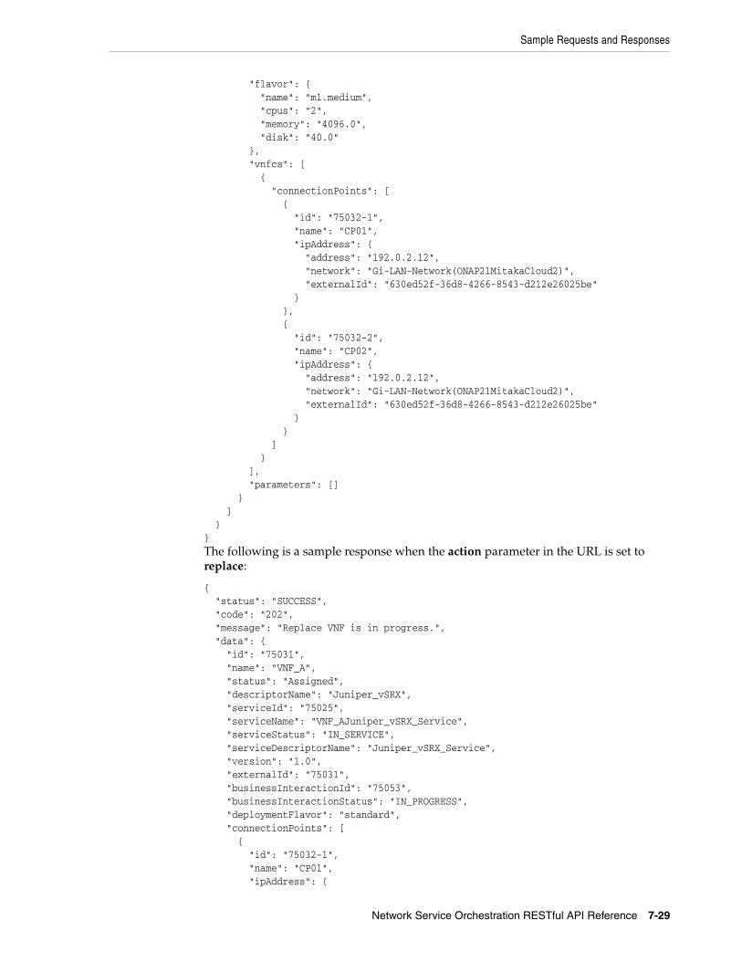
Sample Requests and Responses
Network Service Orchestration RESTful API Reference 7-29
"flavor": { "name": "m1.medium", "cpus": "2", "memory": "4096.0", "disk": "40.0" }, "vnfcs": [ { "connectionPoints": [ { "id": "75032-1", "name": "CP01", "ipAddress": { "address": "192.0.2.12", "network": "Gi-LAN-Network(ONAP21MitakaCloud2)", "externalId": "630ed52f-36d8-4266-8543-d212e26025be" } }, { "id": "75032-2", "name": "CP02", "ipAddress": { "address": "192.0.2.12", "network": "Gi-LAN-Network(ONAP21MitakaCloud2)", "externalId": "630ed52f-36d8-4266-8543-d212e26025be" } } ] } ], "parameters": [] } ] }}The following is a sample response when the action parameter in the URL is set to replace:
{ "status": "SUCCESS", "code": "202", "message": "Replace VNF is in progress.", "data": { "id": "75031", "name": "VNF_A", "status": "Assigned", "descriptorName": "Juniper_vSRX", "serviceId": "75025", "serviceName": "VNF_AJuniper_vSRX_Service", "serviceStatus": "IN_SERVICE", "serviceDescriptorName": "Juniper_vSRX_Service", "version": "1.0", "externalId": "75031", "businessInteractionId": "75053", "businessInteractionStatus": "IN_PROGRESS", "deploymentFlavor": "standard", "connectionPoints": [ { "id": "75032-1", "name": "CP01", "ipAddress": {
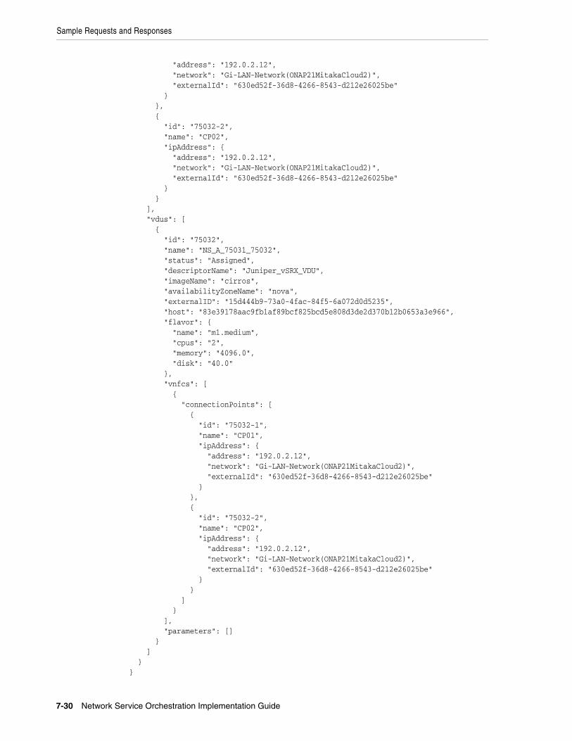
Sample Requests and Responses
7-30 Network Service Orchestration Implementation Guide
"address": "192.0.2.12", "network": "Gi-LAN-Network(ONAP21MitakaCloud2)", "externalId": "630ed52f-36d8-4266-8543-d212e26025be" } }, { "id": "75032-2", "name": "CP02", "ipAddress": { "address": "192.0.2.12", "network": "Gi-LAN-Network(ONAP21MitakaCloud2)", "externalId": "630ed52f-36d8-4266-8543-d212e26025be" } } ], "vdus": [ { "id": "75032", "name": "NS_A_75031_75032", "status": "Assigned", "descriptorName": "Juniper_vSRX_VDU", "imageName": "cirros", "availabilityZoneName": "nova", "externalID": "15d444b9-73a0-4fac-84f5-6a072d0d5235", "host": "83e39178aac9fb1af89bcf825bcd5e808d3de2d370b12b0653a3e966", "flavor": { "name": "m1.medium", "cpus": "2", "memory": "4096.0", "disk": "40.0" }, "vnfcs": [ { "connectionPoints": [ { "id": "75032-1", "name": "CP01", "ipAddress": { "address": "192.0.2.12", "network": "Gi-LAN-Network(ONAP21MitakaCloud2)", "externalId": "630ed52f-36d8-4266-8543-d212e26025be" } }, { "id": "75032-2", "name": "CP02", "ipAddress": { "address": "192.0.2.12", "network": "Gi-LAN-Network(ONAP21MitakaCloud2)", "externalId": "630ed52f-36d8-4266-8543-d212e26025be" } } ] } ], "parameters": [] } ] }}

Sample Requests and Responses
Network Service Orchestration RESTful API Reference 7-31
Scale VNFScales a VNF in a network service by either adding new instances or removing existing instances of the constituent VDUs of the VNF.
MethodPOST
URLhttp://nso_host:port/ocnso/1.1/ns/networkServiceId/scale/vnfId?action=action
where:
■ networkServiceId is the required identifier of the network service for the VNF.
■ vnfId is the required identifier of the VNF to scale.
■ action is the scale action. Specify one of the following values:
– scale-in: Removes the existing instances of constituent VDUs of the specified VNF.
– scale-out: Adds additional instances of constituent VDUs of the specified VNF. This is the default action if the action is not specified.
Sample RequestThis API does not require a request body.
Sample Response{ "status": "SUCCESS", "code": "202", "message": "[INV-431002] VNF scale operation is in progress.", "data": { "id": "150011", "name": "NS_D", "descriptorName": "NPaaS", "status": "IN_SERVICE", "vnfs": [ { "id": "86", "name": "NS_D_Juniper_vSRX_86", "status": "Assigned", "descriptorName": "Juniper_vSRX", "serviceId": "150012", "serviceName": "Juniper_vSRX_Service", "serviceStatus": "IN_SERVICE", "serviceDescriptorName": "Juniper_vSRX_Service", "version": "1.0", "externalId": "86", "businessInteractionId": "150020", "businessInteractionStatus": "IN_PROGRESS", "deploymentFlavor": "standard", "connectionPoints": [ { "id": "87-1", "name": "CP03", "ipAddress": { "address": "192.0.2.12", "network": "nfvo-poc3-mgmt(VIMCloudTest)",

Sample Requests and Responses
7-32 Network Service Orchestration Implementation Guide
"externalId": "2327384b-1ad4-4541-918d-62605ce8d31e" } }, { "id": "87-2", "name": "CP01", "ipAddress": { "address": "192.0.2.13", "network": "150011_Data_IN(VIMCloudTest)", "externalId": "bf4159c0-f830-43bb-a163-8345a0335f46" } }, { "id": "87-3", "name": "CP02", "ipAddress": { "address": "192.0.2.14", "network": "150011_Data_OUT(VIMCloudTest)", "externalId": "c06d13b5-b068-48a0-a5fb-f3000ea2fbce" } }, { "id": "88-1", "name": "CP03", "ipAddress": { "address": "192.0.2.15", "network": "nfvo-poc3-mgmt(VIMCloudTest)", "externalId": "e480b805-612e-44f6-96f2-b5f58bd002be" } }, { "id": "88-2", "name": "CP01", "ipAddress": { "address": "192.0.2.16", "network": "150011_Data_IN(VIMCloudTest)" } }, { "id": "88-3", "name": "CP02", "ipAddress": { "address": "192.0.2.17", "network": "150011_Data_OUT(VIMCloudTest)" } } ], "vdus": [ { "id": "87", "name": "NS_D_86_87", "status": "Assigned", "descriptorName": "Juniper_vSRX_VDU", "imageName": "vsrx-12.1X47-D20.7-npaas-v0.3", "availabilityZoneName": "nova", "externalID": "c131a04c-16bb-40b2-8dc9-59efa731632c", "host": "417ebf996e80c98e2d3781a089a2089b295a1a011e74f0475e4cbdcb", "flavor": { "name": "vsrx.medium", "cpus": "2",

Sample Requests and Responses
Network Service Orchestration RESTful API Reference 7-33
"memory": "4096.0", "disk": "20.0" }, "vnfcs": [ { "connectionPoints": [ { "id": "87-1", "name": "CP03", "ipAddress": { "address": "192.0.2.20", "network": "nfvo-poc3-mgmt(VIMCloudTest)", "externalId": "2327384b-1ad4-4541-918d-62605ce8d31e" } }, { "id": "87-2", "name": "CP01", "ipAddress": { "address": "192.0.2.21", "network": "150011_Data_IN(VIMCloudTest)", "externalId": "bf4159c0-f830-43bb-a163-8345a0335f46" } }, { "id": "87-3", "name": "CP02", "ipAddress": { "address": "192.0.2.22", "network": "150011_Data_OUT(VIMCloudTest)", "externalId": "c06d13b5-b068-48a0-a5fb-f3000ea2fbce" } } ] } ], "parameters": [] }, { "id": "88", "name": "NS_D_86_88", "status": "Pending Assign", "descriptorName": "Juniper_vSRX_VDU", "imageName": "vsrx-12.1X47-D20.7-npaas-v0.3", "availabilityZoneName": "nova", "flavor": { "name": "vsrx.medium", "cpus": "2", "memory": "4096.0", "disk": "20.0" }, "vnfcs": [ { "connectionPoints": [ { "id": "88-1", "name": "CP03", "ipAddress": { "address": "192.0.2.32", "network": "nfvo-poc3-mgmt(VIMCloudTest)",

Sample Requests and Responses
7-34 Network Service Orchestration Implementation Guide
"externalId": "e480b805-612e-44f6-96f2-b5f58bd002be" } }, { "id": "88-2", "name": "CP01", "ipAddress": { "address": "192.0.2.33", "network": "150011_Data_IN(VIMCloudTest)" } }, { "id": "88-3", "name": "CP02", "ipAddress": { "address": "192.0.2.34", "network": "150011_Data_OUT(VIMCloudTest)" } } ] } ], "parameters": [] } ] } ] }}
Get VNF DetailsRetrieves the details about a VNF given the input VNF identifier.
MethodGET
URLhttp://nso_host:port/ocnso/1.1/vnf/vnfId
where vnfId is the identifier of the VNF.
Sample Response{ "status": "SUCCESS", "code": "200", "data": { "id": "1500001", "name": "NSO_E", "status": "Assigned", "descriptorName": "Juniper_vSRX", "serviceId": "1575002", "serviceName": "NSO_EJuniper_vSRX_Service", "serviceStatus": "IN_SERVICE", "serviceDescriptorName": "Juniper_vSRX_Service", "version": "1.0", "externalId": "1500001", "businessInteractionId": "1575002",

Sample Requests and Responses
Network Service Orchestration RESTful API Reference 7-35
"businessInteractionStatus": "COMPLETED", "deploymentFlavor": "standard", "connectionPoints": [ { "id": "1500002-1", "name": "CP03", "ipAddress": { "address": "192.0.2.12", "network": "nfvo-poc3-mgmt(ONAP21MitakaCloud2)", "externalId": "4c8d514b-f933-4065-8baa-fab1556c6381" } }, { "id": "1500002-2", "name": "CP01", "ipAddress": { "address": "192.0.2.13", "network": "1575001_Data_IN(ONAP21MitakaCloud2)", "externalId": "c4ee6127-c29f-489d-9993-732e822052c2" } }, { "id": "1500002-3", "name": "CP02", "ipAddress": { "address": "192.0.2.14", "network": "1575001_Data_OUT(ONAP21MitakaCloud2)", "externalId": "ed241427-a429-46c1-8425-dd1a89e5ec77" } } ], "vdus": [ { "id": "1500002", "name": "NSO_NS_E_1500001_1500002", "status": "Assigned", "descriptorName": "Juniper_vSRX_VDU", "imageName": "vsrx-12.1X47-D20.7-npaas-v0.3", "availabilityZoneName": "nova", "externalID": "f3ab2c68-3746-4ab1-a17d-e24771b420f6", "host": "417ebf996e80c98e2d3781a089a2089b295a1a011e74f0475e4cbdcb", "flavor": { "name": "vsrx.medium", "cpus": "2", "memory": "4096.0", "disk": "20.0" }, "vnfcs": [ { "connectionPoints": [ { "id": "1500002-1", "name": "CP03", "ipAddress": { "address": "192.0.2.21", "network": "nfvo-poc3-mgmt(ONAP21MitakaCloud2)", "externalId": "4c8d514b-f933-4065-8baa-fab1556c6381" } }, {

Sample Requests and Responses
7-36 Network Service Orchestration Implementation Guide
"id": "1500002-2", "name": "CP01", "ipAddress": { "address": "192.0.2.22", "network": "1575001_Data_IN(ONAP21MitakaCloud2)", "externalId": "c4ee6127-c29f-489d-9993-732e822052c2" } }, { "id": "1500002-3", "name": "CP02", "ipAddress": { "address": "192.0.2.23", "network": "1575001_Data_OUT(ONAP21MitakaCloud2)", "externalId": "ed241427-a429-46c1-8425-dd1a89e5ec77" } } ] } ], "parameters": [] } ] }}
Get VNF StatusRetrieves the status information of a VNF and the VIM given the input VNF identifier.
MethodGET
URLhttp://nso_host:port/ocnso/1.1/vnf/vnfId/status
where vnfId is the identifier of the VNF.
Sample Response{ "status": "SUCCESS", "code": "200", "data": { "id": "75085", "name": "ChkptVNF_CP_B253", "status": "Assigned", "descriptorName": "Checkpoint_NG_FW" }}
Heal VDUHeals a VDU by rebooting the virtual machine on which the VDU is deployed.
MethodPOST

Sample Requests and Responses
Network Service Orchestration RESTful API Reference 7-37
URLhttp://nso_host:port/ocnso/1.1/vnf/vnfId/vdus/vduId/heal
where:
■ vnfId is the required identifier of the VNF.
■ vduId is the required identifier of the VDU.
Sample RequestThis API does not require a request body.
Sample Response{ "status": "SUCCESS", "code": "200", "data": "VDU has been healed successfully"}
Register PNFRegisters or creates a new PNF in inventory.
MethodPOST
URLhttp://nso_host:port/ocnso/1.1/pnfs
Before registering a PNF, you must register the EMS. In the PNF registration request, specify the ID of the EMS in the id attribute under the management parameter.
Sample Request{ "name": "xtv59", "descriptorName": "Cisco_xRV", "description": "", "userName": "user", "pswd": "password", "sslEnabled": false, "sshKey": "7b:ab:75:32:9e:b6:6c:4b:29:dc", "ipAddress": "192.0.2.252", "management": { "id": "225001", "name": "ems5111", "mgmtInterface": "EMS", "descriptorName": "Cisco_xRV_EMS" }, "parameters": []}
Sample Response{ "status": "SUCCESS", "code": "200", "data": { "id": "525003",

Sample Requests and Responses
7-38 Network Service Orchestration Implementation Guide
"name": "xtv598912", "descriptorName": "Cisco_xRV", "description": "", "ipAddress": "192.0.2.252", "userName": "user", "pswd": "****", "sslEnabled": false, "sshKey": "7b:ab:75:32:9e:b6:6c:4b:29:dc", "parameters": [ {} ], "management": { "id": "225001", "name": "ems5111", "mgmtInterface": "EMS", "descriptorName": "Cisco_xRV_EMS" } }}
Update PNFUpdates an existing registered PNF. The update persists the new attribute values to the inventory database.
MethodPUT
URLhttp://nso_host:port/ocnso/1.1/pnfs/pnfId
where pnfId is the identifier of the PNF that you want to update.
Sample Request{ "pswd": "password", "sshKey": "7b:ab:75:32:9e:b6:6c:4b:29:dc"}
Sample Response{ "status": "SUCCESS", "code": "200", "data": { "id": "525003", "name": "xtv598912", "descriptorName": "Cisco_xRV", "description": "", "ipAddress": "192.0.2.252", "userName": "user", "pswd": "****", "sslEnabled": false, "sshKey": "7b:ab:75:32:9e:b6:6c:4b:29:dc", "parameters": [ {} ] }}

Sample Requests and Responses
Network Service Orchestration RESTful API Reference 7-39
Get PNFsRetrieves the list of active PNFs that are related to the input PNF descriptor.
MethodGET
URLhttp://nso_host:port/ocnso/1.1/pnfs?descriptorName=pnfdName
where pnfdName is the name of the PNF descriptor.
Sample Response{ "status": "SUCCESS", "code": "200", "data": [ { "id": "22001", "name": "xtv0018", "descriptorName": "Cisco_xRV", "ipAddress": "192.0.2.228", "userName": "user2", "pswd": "****", "sslEnabled": false, "sshKey": "", "parameters": [ {} ], "management": {} }, { "id": "300012", "name": "xtv592", "descriptorName": "Cisco_xRV", "ipAddress": "192.0.2.226", "userName": "user8", "pswd": "****", "sslEnabled": false, "sshKey": "", "parameters": [ {} ], "management": { "id": "75007", "name": "ems363", "mgmtInterface": "EMS", "descriptorName": "Cisco_xRV_EMS" } }, { "id": "300016", "name": "xtv595", "descriptorName": "Cisco_xRV", "ipAddress": "192.0.2.227", "userName": "user5", "pswd": "****", "sslEnabled": false, "sshKey": "",

Sample Requests and Responses
7-40 Network Service Orchestration Implementation Guide
"parameters": [ {} ], "management": {} } ]}
Get PNF DetailsRetrieves the details of a PNF given the PNF identifier.
MethodGET
URLhttp://nso_host:port/ocnso/1.1/pnfs/pnfId
where pnfdId is the identifier of the PNF that you want to retrieve.
Sample Response{ "status": "SUCCESS", "code": "200", "data": { "id": "525003", "name": "xtv59", "descriptorName": "Cisco_xRV", "description": "", "ipAddress": "192.0.2.224", "userName": "user", "pswd": "****", "sslEnabled": false, "sshKey": "", "parameters": [ {} ], "management": { "id": "225001", "name": "ems5111", "mgmtInterface": "EMS", "descriptorName": "Cisco_xRV_EMS" } }}
Unregister PNFUnregisters an existing PNF. The request deletes the PNF matching the input identifier value from the inventory database.
MethodDELETE
URLhttp://nso_host:port/ocnso/1.1/pnfs/pnfId

Sample Requests and Responses
Network Service Orchestration RESTful API Reference 7-41
where pnfId is the identifier of the PNF that you want to unregister.
Sample RequestThis API does not require a request body.
Sample Response{ "status": "SUCCESS", "code": "200", "message": "[INV-430925] PNF 300007 is deleted successfully."}
Register EMSRegister or create a new EMS in inventory.
MethodPOST
URLhttp://nso_host:port/ocnso/1.1/ems
Sample Request{ "name": "ems574", "descriptorName": "Cisco_xRV_EMS", "description": "Sample Description", "userName": "user", "pswd": "password", "ipAddress": "192.0.2.212", "port": "7001", "sslEnabled": false, "protocol": "REST"}
Sample Response{ "status": "SUCCESS", "code": "200", "data": { "id": "375003", "name": "ems574", "descriptorName": "Cisco_xRV_EMS", "description": "Sample Description", "ipAddress": "192.0.2.212", "port": "7001", "userName": "user", "pswd": "****", "sslEnabled": false, "protocol": "REST", "parameters": [ {} ] }}

Sample Requests and Responses
7-42 Network Service Orchestration Implementation Guide
Update EMSUpdates the details of a registered EMS in inventory. The update persists the new attribute values to the inventory database.
MethodPUT
URLhttp://nso_host:port/ocnso/1.1/ems/emsId
where emsId is the identifier of the EMS that you want to update.
Sample Request{ "description": "New EMS description", "userName": "sys_user_1", "pswd": "password"}
Sample Response{ "status": "SUCCESS", "code": "200", "data": { "id": "375003", "name": "ems574236312", "descriptorName": "Cisco_xRV_EMS", "description": "New EMS description", "ipAddress": "192.0.2.212", "port": "7001", "userName": "sys_user_1", "pswd": "****", "sslEnabled": false, "protocol": "REST", "parameters": [ {} ] }}
Get EMSsRetrieves the list of active EMSs that are related to the input EMS descriptor.
MethodGET
URLhttp://nso_host:port/ocnso/1.1/ems?descriptorName=emsdName
where emsdName is the name of the EMS descriptor.
Sample Response{ "status": "SUCCESS", "code": "200",

Sample Requests and Responses
Network Service Orchestration RESTful API Reference 7-43
"data": [ { "id": "225001", "name": "ems5111", "descriptorName": "Cisco_xRV_EMS", "description": "description", "ipAddress": "192.0.2.221", "port": "1234", "userName": "user", "pswd": "****", "sslEnabled": false, "protocol": "REST", "parameters": [ {} ] }, { "id": "375001", "name": "ems5742", "descriptorName": "Cisco_xRV_EMS", "description": "description", "ipAddress": "192.0.2.222", "port": "12345", "userName": "user", "pswd": "****", "sslEnabled": false, "protocol": "REST", "parameters": [ {} ] } ]}
Get EMS DetailsRetrieves the details of an EMS given the EMS identifier.
MethodGET
URLhttp://nso_host:port/ocnso/1.1/ems/emsId
where emsId is the identifier of the EMS that you want to retrieve.
Sample Response{ "status": "SUCCESS", "code": "200", "data": { "id": "375003", "name": "ems5742", "descriptorName": "Cisco_xRV_EMS", "description": "description", "ipAddress": "192.0.2.220", "port": "1234", "userName": "user11",

Sample Requests and Responses
7-44 Network Service Orchestration Implementation Guide
"pswd": "****", "sslEnabled": false, "protocol": "REST", "parameters": [ {} ] }}
Unregister EMSUnregisters an existing EMS. The request deletes the EMS matching the input identifier value from the inventory database.
MethodDELETE
URLhttp://nso_host:port/ocnso/1.1/ems/emsId
where emsId is the identifier of the EMS that you want to unregister.
Sample RequestThis API does not require a request body.
Sample Response{ "status": "SUCCESS", "code": "200", "message": "[INV-430936] EMS 75003 is deleted successfully."}
Get Network Service DescriptorsRetrieves a list of deployed network service descriptors.
MethodGET
URLhttp://nso_host:port/ocnso/1.1/nsd
Sample Response{ "status": "SUCCESS", "code": "200", "data": [ "NPaas", "P-CSCF", "ResidentialGateway" ]}

Sample Requests and Responses
Network Service Orchestration RESTful API Reference 7-45
Get Network Service Descriptor DetailsRetrieves details about a specified network service descriptor.
MethodGET
URLhttp://nso_host:port/ocnso/1.1/nsd/nsdName
where nsdName is the name of the network service descriptor.
Sample Response{ "status": "SUCCESS", "code": "200", "data": { "name": "NPaaS", "virtualLinks": [ { "id": "ManagementNetwork", "name": "ManagementNetwork", "referencedCPs": [ { "id": "CP03", "name": "CP03", "type": "MANAGEMENT", "vnfdId": "Juniper_vSRX" }, { "id": "CP03", "name": "CP03", "type": "MANAGEMENT", "vnfdId": "Checkpoint_NG_FW" } ] }, { "id": "Data_IN", "name": "Data_IN", "referencedCPs": [ { "id": "CP01", "name": "CP01", "type": "EXTERNAL", "vnfdId": "Juniper_vSRX" }, { "id": "CP01", "name": "CP01", "type": "EXTERNAL", "vnfdId": "Checkpoint_NG_FW" } ] }, { "id": "Data_OUT", "name": "Data_OUT", "referencedCPs": [

Sample Requests and Responses
7-46 Network Service Orchestration Implementation Guide
{ "id": "CP02", "name": "CP02", "type": "EXTERNAL", "vnfdId": "Juniper_vSRX" }, { "id": "CP02", "name": "CP02", "type": "EXTERNAL", "vnfdId": "Checkpoint_NG_FW" } ] } ], "deploymentFlavors": [ { "name": "Checkpoint", "constituentVNFs": [ { "vnfRefId": "Checkpoint_NG_FW", "deploymentFlavorReference": "standard", "minInstances": 1, "maxInstances": 1 } ] }, { "name": "Juniper", "constituentVNFs": [ { "vnfRefId": "Juniper_vSRX", "deploymentFlavorReference": "standard", "minInstances": 1, "maxInstances": 1 } ] } ], "referencedVNFs": [ "Checkpoint_NG_FW", "Juniper_vSRX" ], "forwardingGrpahs": [ { "id": "data-vnffg", "name": "data-vnffg", "isDefault": false, "referredVNFDs": [ "Juniper_vSRX" ], "referredVLDs": [], "referredEndpoints": [ "Service_EP1", "Service_EP2" ], "forwardingPaths": [ { "id": "nfp1", "name": "nfp1",

Sample Requests and Responses
Network Service Orchestration RESTful API Reference 7-47
"forwardingPolicy": "SYMMETRIC", "sourceEndpoint": "Service_EP1", "destinationEndpoint": "Service_EP2", "connectionPoints": [ "CP01", "CP02" ] } ] } ], "policies": [ { "id": "premium", "name": "premium", "type": "traffic-classification", "rules": [ { "id": "rule1", "name": "rule1", "type": "traffic-classification", "action": "nfp-ref-id:nfp1", "referredFG": "data-vnffg", "params": [ { "name": "protocol", "value": "UDP" } ] } ] }, { "id": "standard", "name": "standard", "type": "traffic-classification", "rules": [ { "id": "rule1", "name": "rule1", "type": "traffic-classification", "action": "nfp-ref-id:nfp1", "referredFG": "data-vnffg", "params": [ { "name": "protocol", "value": "UDP" } ] } ] } ] }}
Get Network Service Descriptor VNFDsRetrieves a list of VNF descriptors that a network service descriptor references.

Sample Requests and Responses
7-48 Network Service Orchestration Implementation Guide
MethodGET
URLhttp://nso_host:port/ocnso/1.1/nsd/nsdName/vnfds
where nsdName is the name of the network service descriptor.
Sample Response{ "status": "SUCCESS", "code": "200", "data": [ "Checkpoint_NG_FW", "Juniper_vSRX" ]}
Get Network Service Descriptor FlavorsRetrieves a list of deployment flavors for a specified network service descriptor.
MethodGET
URLhttp://nso_host:port/ocnso/1.1/nsd/nsdName/flavors
where nsdName is the name of the network service descriptor.
Sample Response{ "status": "SUCCESS", "code": "200", "data": [ { "name": "Checkpoint", "constituentVNFs": [ { "vnfRefId": "Checkpoint_NG_FW", "deploymentFlavorReference": "standard", "minInstances": 1, "maxInstances": 1 } ] }, { "name": "Juniper", "constituentVNFs": [ { "vnfRefId": "Juniper_vSRX", "deploymentFlavorReference": "standard", "minInstances": 1, "maxInstances": 1 } ] }

Sample Requests and Responses
Network Service Orchestration RESTful API Reference 7-49
]}
Get VNF Descriptor DetailsRetrieves details about a specified VNF descriptor.
MethodGET
URLhttp://nso_host:port/ocnso/1.1/vnfd/vnfdName
where vnfdName is the name of the VNF descriptor.
Sample Response{ "status": "SUCCESS", "code": "200", "data": { "id": "Juniper_vSRX", "name": "Juniper_vSRX", "vendor": "Oracle", "version": "1.0", "vdus": [ { "id": "Juniper_vSRX_VDU", "name": "Juniper_vSRX_VDU", "imageReference": "vsrx-v1.0", "vnfComponents": [ { "id": "vsrxc", "name": "vsrxc", "connectionPoints": [ { "id": "CP03", "name": "CP03", "type": "MANAGEMENT", "vnfdId": "Juniper_vSRX" }, { "id": "CP01", "name": "CP01", "type": "EXTERNAL", "vnfdId": "Juniper_vSRX" }, { "id": "CP02", "name": "CP02", "type": "EXTERNAL", "vnfdId": "Juniper_vSRX" } ] } ] } ], "deploymentFlavors": [

Sample Requests and Responses
7-50 Network Service Orchestration Implementation Guide
{ "id": "standard", "name": "standard", "constituentVDUs": [ { "minInstances": 1, "maxInstances": 1, "constituentVNFCs": [ { "vnfcReference": "vsrxc", "minInstances": 1, "maxInstances": 1 } ], "id": "Juniper_vSRX_VDU", "flavorID": "vsrx.medium" } ] } ], "connectionPoints": [ { "id": "CP03", "name": "CP03", "type": "MANAGEMENT", "vnfdId": "Juniper_vSRX" }, { "id": "CP01", "name": "CP01", "type": "EXTERNAL", "vnfdId": "Juniper_vSRX" }, { "id": "CP02", "name": "CP02", "type": "EXTERNAL", "vnfdId": "Juniper_vSRX" } ], "vduImages": [ { "id": "vsrx-v1.0", "softwareImages": [ { "extensionsImpl": [ { "type": "ImageCredentials", "handler": "oracle.communications.inventory.nso.extensions.impl.ImageCredentialsHandlerImpl", "params": [ { "name": "username", "value": "root" }, { "name": "password", "value": "labms01" } ]

Sample Requests and Responses
Network Service Orchestration RESTful API Reference 7-51
} ], "name": "vsrx-12.1X47-D20.7-npaas-v0.3", "version": "1.0", "extensions": [ { "type": "ImageCredentials", "handler": "oracle.communications.inventory.nso.extensions.impl.ImageCredentialsHandlerImpl", "params": [ { "name": "username", "value": "root" }, { "name": "password", "value": "labms01" } ] } ] } ] } ] "vduFlavors": [ { "id": "vsrx.small", "cpus": "2", "memory": "2048.0", "disk": "20.0" }, { "id": "vsrx.medium", "cpus": "2", "memory": "4096.0", "disk": "20.0" }, { "id": "m1.medium", "cpus": "2", "memory": "4096.0", "disk": "40.0" } ] }}
Get VNF Descriptor FlavorsRetrieves the list of VNF flavors of a specified VNF descriptor.
MethodGET
URLhttp://nso_host:port/ocnso/1.1/vnfd/vnfdName/flavors
where vnfdName is the name of the VNF descriptor.

Sample Requests and Responses
7-52 Network Service Orchestration Implementation Guide
Sample Response{ "status": "SUCCESS", "code": "200", "data": [ { "id": "standard", "name": "standard", "constituentVDUs": [ { "minInstances": 1, "maxInstances": 1, "constituentVNFCs": [ { "vnfcReference": "vsrxc", "minInstances": 1, "maxInstances": 1 } ], "id": "Juniper_vSRX_VDU", "flavorID": "vsrx.medium" } ] } ]}


![Oracle Communications Platform® Communications Platform TPD Initial Product ... [2] Oracle Integrated ...](https://static.documents.pub/doc/80x56/5afcad0d7f8b9a994d8c6cf9/oracle-communications-platform-communications-platform-tpd-initial-product-2.jpg)


