1 Senior Asst. Professor, Tagore Engineering College, E-mail: [email protected] Professor, EEE, Jerusalem College of Engineering, E-mail: [email protected] PG Scholar, Tagore Engineering College, E-mail: [email protected]
Implementation of ACO Techniques in highvoltage gain converter for SPV System underpartial shading conditionS. Sasikala1, V. Jamuna2 and R. Saranya3
ABSTRACT
Partial shading of a photovoltaic array reduces its output power. In this paper a converter which is used to improvethe voltage level by combining the traditional buck- boost converter and KY Converter and maintain the outputvoltage constant but irrespective of change in input voltage. Then Performance of converter can be improved byusing controller tuned by one of the neural network techniques of ANT Colony optimization techniques.
Index Terms: Charge pump, Coupled inductor, KY converter, ACO, PI Controller.
1. INTRODUCTION
Due the recompense decreased effect of global warming and increasing the demand of power the renewableenergy come in engage in recreation as a significant role. Compare to non-conventional energy source,renewable energy usage is increasing, like PV installation for several application. The photovoltaic (PV)industry is experiencing rapid growth due to improving technology, lower cost, government subsidies,standardized interconnection to the electric utility grid, and public enthusiasm for an environmentally benignenergy source. PV system sizes vary from the MW range, in utility applications, down to the KW range inresidential applications. The shaded area and reduction in solar irradiance, causing the decrease in powerproduction and leads to the shading factor. Power producing from the solar panel is not adequate to meetthe power the equipments in different applications. For that we are proposing the high voltage gain converterfor boost up voltage gain based on change in the environmental condition and which load changes [2].
Concerning the traditional non- isolated voltage-boosting converters such as the traditional buck-boostconverter and boost converter, their voltage gains are not high enough [3], [4],. Many techniques are incorporatedlike several inductors connected in series, auxiliary transformer with turn’s ratio etc, but these techniquesare increasing components and conversion complexity. In this paper discussed the electrical characteristics’performance of the high voltage gain converter. This converter is a combination of KY Converter andtradition buck-boost converter and one coupled inductor with turn’s ratio [2] and in addition to which itsperformance of converter can be improved by using controller that is tuned by using swarm optimizationtechniques like ANT Colony optimization techniques.
2. SOLAR PANEL
Current from the solar panel is inherently direct current. Fig. 1 shows the equivalent circuit of solar cell.Performance of PV panel is analyzed based on the PV and an IV characteristic, under a non-uniforminsolation due to partial shading.
810 S. Sasikala, V. Jamuna and R. Saranya
Figure 1: Equivalent circuit of solar cell
3. HIGH VOLTAGE GAIN CONVERTER CONFIGURATION
The KY converter has a special feature of enlarge the voltage ratio provided individual inductors Therefore,the proposed converter has a higher voltage gain compare to the converter in [5] and can be determined byadjusting both the duty cycle and the turn’s ratio. KY converter is referred as high voltage gain Furthermore,the duty cycle and the turns ratios are independent, which way that tuning the duty cycle does not affect theturn’s ratio and vice versa. In addition, the proposed high voltage gain converter has an output inductor sothere is no floating output. Hence, the output current is not pulsating.
Proposed converter shown in Fig 2, this converter consists of two MOSFET switches (S1& S2),onecoupled inductor of primary and secondary winding (N
p and N
s), three capacitors are used for energy
transferring C1,second capacitor act as a charge pump C2 ,and third one is used as a output capacitor C
0 , L
0
act as output inductor. In addition it contains input voltage is Vi, the output voltage is V
0 , and R
0 represents
a output resistor. In coupled inductor, primary winding consists of magnetizing inductor and leakage inductorwhich is connected in parallel and series respectively with primary winding. Therefore k is defined as acoupling coefficient L
m / (L
m+L
l1), output inductor L
0 is connected in series with secondary winding and
current flowing through Lm ,
L0 are always positive.
Figure 2: High Voltage gain converter
4. OPERATING PRINCIPLE OF CONVERTER
There are two operating modes for high voltage gain converter. Duty cycle for the two MOSFET is (D-1)and D, where D represents a duty cycle is defined from the controller. Here the Coupling coefficient k istaking as one for both modes, therefore leakage inductor is neglected.
Mode 1: During this period, shown in fig 4, S1 is turned off and S
2 turned on. when voltage V
i appeared
across Np , that causes inductor which is connected in parallel with N
p get magnetized and voltage is induced
across Ns.
therefore diode D1 get forward biased, the capacitor C
2 is charging, voltage appeared across the
output inductor is negative, thus making L0 get demagnetized.
Implementation of ACO Techniques in High Voltage Gain Converter for SPV System... 811
VNs
= Vi x (N
s/N
p ) (1)
C2 = V
i + V
c1+(V
i x (N
s/N
p)) (2)
VL0
= VC2
–V0
(3)
VNp
= Vi
(4)
Therefore supply voltage Vi, together with C
1, plus voltage induced across N
s and voltage across L
0,
provides the energy to the load.
Mode 2: During this period, as shown in Fig 5, Switch S1 is turned on, S
2 is turned off. Therefore
negative voltage VC1
is imposed on NP. So that L
m gets demagnetized, such that voltage is induced across N
s.
Figure 3: High Voltage gain converter
Figure 4: Power flow diagram when switch S1 is OFF
Figure 5: Power flow diagram when switch S1 is ON
812 S. Sasikala, V. Jamuna and R. Saranya
Therefore diode get reverse bias, C2 start to discharging, then Voltage across L
0 get positive, thus causing
the output inductor is magnetized.
VNs
= - VC1
x Ns / N
P(5)
VL0
= Vi + VC1
+VC2
–V0
(6)
VNp
= - VC1
(7)
As a consequence supply voltage Vi, together with voltage across L
m, plus the voltage across C
2, provides
the energy to the load and output inductor L0.
By applying the voltage, second balance principle to Lm and L
0 over one switching period, the following
equations can be obtained as,
For Lm,
Vi *
D + (-VC1
) * (1-D) = 0 (8)
The voltage across C1,
VC1
= (D / (1-D)) * Vi
(9)
For L0,
(VC2
-V0) * D + (V
i +V
C1+V
C2-V
0) *(1-D) = 0 (10)
The voltage across C2,
VC2
= Vi +V
C1 + V
i * (N
S/N
P) (11)
From equation VC1
and VC2
, The Voltage gain becomes,
V0 /
Vi = ((2-D)/ (1-D)) + (N
S/N
P) (12)
From equation (12) D is varies between
0 < D < 1
5. HIGH VOLTAGE GAIN CONVERTER WITH PI CONTROLLER
PI controller provides stability, offers zero steady state error. The disadvantages are remunerated at thesame time with P & I controllers. By using this controller can maintain the constant output voltage bycompare the reference voltage and actual output voltage obtained from the converter.
Figure 6: MATLAB simulation for high voltage gain converter with PI Controller
Implementation of ACO Techniques in High Voltage Gain Converter for SPV System... 813
When comparing there is no error, the controller output is remains constant. At the time t=0, theobservation is started. If error not settled at zero, propositional term used for correction and based on theerror sign, integral term contribute to increase or decrease the accumulated value in forward or reversedirection. Main advantage of this type is integral term eliminate the offset. Based on error value, thiscontroller output determine the duty cycle for converter to maintain the constant output voltage.[13] Converteris operated for different input voltage (15V to 21V) obtained from solar module and load conditions. PIcontroller output is depends upon the error signal. Fig 6 shows the simulation circuit in which, for a giveninput voltage, output voltage of converter is compare with the reference voltage of 80V and determine theerror signal this signal sends to as a input for PI controller. Duty cycle of the controller is changes based onthe input it is determined by the PWM, this switching frequency will be 20 KHz
6. ANT COLONY OPTIMIZATION
The ant colony optimization (ACO) is swarm optimization technique based on the behavior of ants seekinga path between their colony and a source of food. ACO is belongs to heuristic algorithm and based on thereal ant behavior.
A colony of ants is passes in two possible paths. At initial condition each ant chooses the path randomly.The ant chooses the shortest path will come back faster than other. This shortest path chosen based on thepheromones deposited on that path.
The pheromone � = {�ij}
Initial condition ô is defines as
�ij= �
0 (i,j), where �0 > 0. (13)
The probability for node j at node i is defined as
*( )
, *, € ( )
( ) , € 04ij ijA Ai j A
i j T ij ij
P t if i j T� �
�
� �� �� � � (14)
� and � are constant value it determines the corresponding pheromone and heuristic function on decisionof ant.
The capacity of pheromone ��ij
A on each path can write as
1/ , €
0
A AAij
L if i j T�� � �
�� � �� �
(15)
Evaporation of pheromone is way to avoid unlimited of pheromone trails.
�ij�(1 - �) * �ij + �A=1
NA ��ij
A(t) (16)
Where � is the evaporation rate, NA is the number of ants. Advantage of ACO is the ability of the algorithmto run continuously while adapting to changes in real time.
7. ACO TUNED PI CONTROLLER AND CONVERTER
Optimal value of KP and K
I is determined by using the ACO. The main objective of optimal controller
design is to reduce the peak over shoot and output voltage maintained as constant.KP and K
I are randomly
selected at each node, which gives the solution. These values are kept on changing from resource to objective.After taking more iteration to complete path the solution is found. Minimum overshoot is calculated andcompare with other node solution to describe the good solution.
814 S. Sasikala, V. Jamuna and R. Saranya
In High voltage gain converter, changes in the input voltage based on the environmental condition aswell as load changes, it not maintain the output voltage constant at 80V.for maintain the output voltageconstant by using PI controller but in the output having the peak over shoot, oscillation, efficiency andsettling time problems are occur due to changes in input and load condition this can be overcome byoptimization techniques. Fig 7 shows the ACO tuned High voltage gain converter.
Figure 7: ACO tuned High voltage gain converter
8. SIMULATION RESULTS
Fig. 8 (a), (b) shows IV and PV characteristics in normal condition (without shading). Under normal conditionthe solar system shading will not be presented and generated power will be normal. The generated peakvoltage, current & power values are 21V, 7.6A & 159.6W respectively. The maximum power point of119.7W at the voltage and current are 17V and 7.04A.
Figure 8: (a),(b) IV and PV characteristics in Normal condition
Fig 9 (a),(b) shows the IV and PV characteristics under different partial shading condition of 0 and 0.05in p.u . At the irradiance level peak voltage, current and power values are 15.5 V, 0.148A & 2.294 W. Fig 10(a),(b) shows the IV and PV characteristics under partial shading condition of 1 and 0.5 in p.u .
Implementation of ACO Techniques in High Voltage Gain Converter for SPV System... 815
At this condition, peak voltage, current and power values are 20.638V, 5.8 A & 119.7 W. The maximumpower point of 95.7W is obtained at the point of voltage & current is 16.9 V & 5.6 A.
Therefore the power output obtained from solar panel is not high and efficiency is very low. We haveto improve the utilization of solar panel by improving the power output. This can be achieved by using theproposed high voltage gain converter. This can be discussed by following. Fig 11,12 shows the simulationresult of output voltage, current and Power of 51.5V , 0.015A and 0.07W obtained from the converter underthe partial shading condition of 0 & 0.05 p.u, as a input to the converter
Figure 10: (a),(b) IV and PV characteristics under shading condition of 1 & 0.5 p.u
Figure 9: (a),(b) IV and PV characteristics under shading condition of 0 & 0.05 p.u
Figure 11: Output voltage of converter under partial shading of 0 & 0.05 p.u
816 S. Sasikala, V. Jamuna and R. Saranya
Fig 13, 14 shows the simulation result of output voltage, current and Power of 68.75V, 0.0687A and3.76W obtained from the converter under the partial shading condition of 1 & 0.5 p.u, as an input to theconverter.
The simulation is carried for different shading condition(0 p.u to 1 p.u ) and load condition while theoutput voltage is maintained at constant level of 80V.To maintain the output voltage based on environmentalcondition ,duty cycle of the switches S
1, S
2 is changed.
Figure 12: Output voltage of converter under partial shading of 0 & 0.05 p.u
Figure 13: Output voltage of converter under partial shading of 1 & 0.5 p.u
Figure 14: Output current of converter under partial shading of 1 & 0.5 p.u.
Implementation of ACO Techniques in High Voltage Gain Converter for SPV System... 817
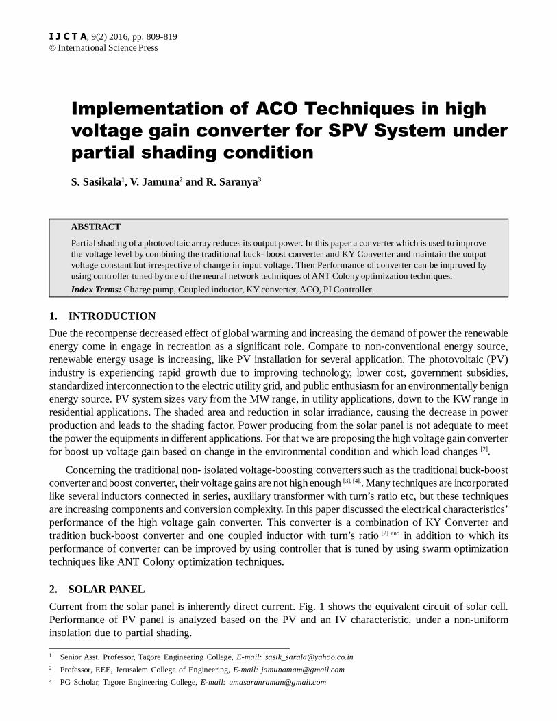
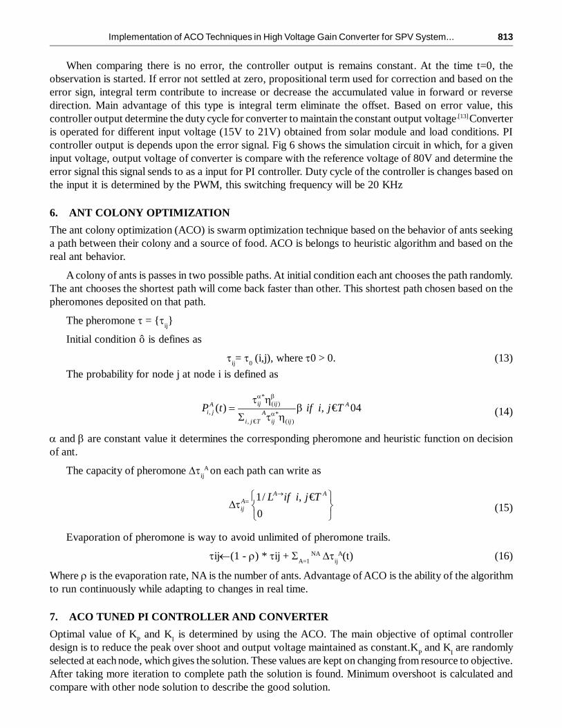
The input changes from (0 p.u to 1 p.u), Fig 15, shows the output voltage contains peak over shoot andripples. By using the PI controller we reduce the peak over shoot and ripples. For the input voltage of 15V,load resistance of 100 ohms, controller of PI parameter K
P , K
I is 1,10 respectively. From the simulation
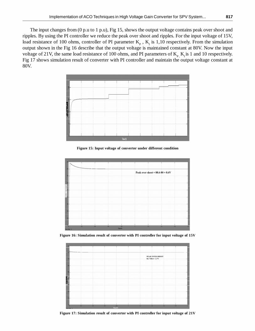
output shown in the Fig 16 describe that the output voltage is maintained constant at 80V. Now the inputvoltage of 21V, the same load resistance of 100 ohms, and PI parameters of K
P , K
I is 1 and 10 respectively.
Fig 17 shows simulation result of converter with PI controller and maintain the output voltage constant at80V.
Figure 15: Input voltage of converter under different condition
Figure 16: Simulation result of converter with PI controller for input voltage of 15V
Figure 17: Simulation result of converter with PI controller for input voltage of 21V
818 S. Sasikala, V. Jamuna and R. Saranya
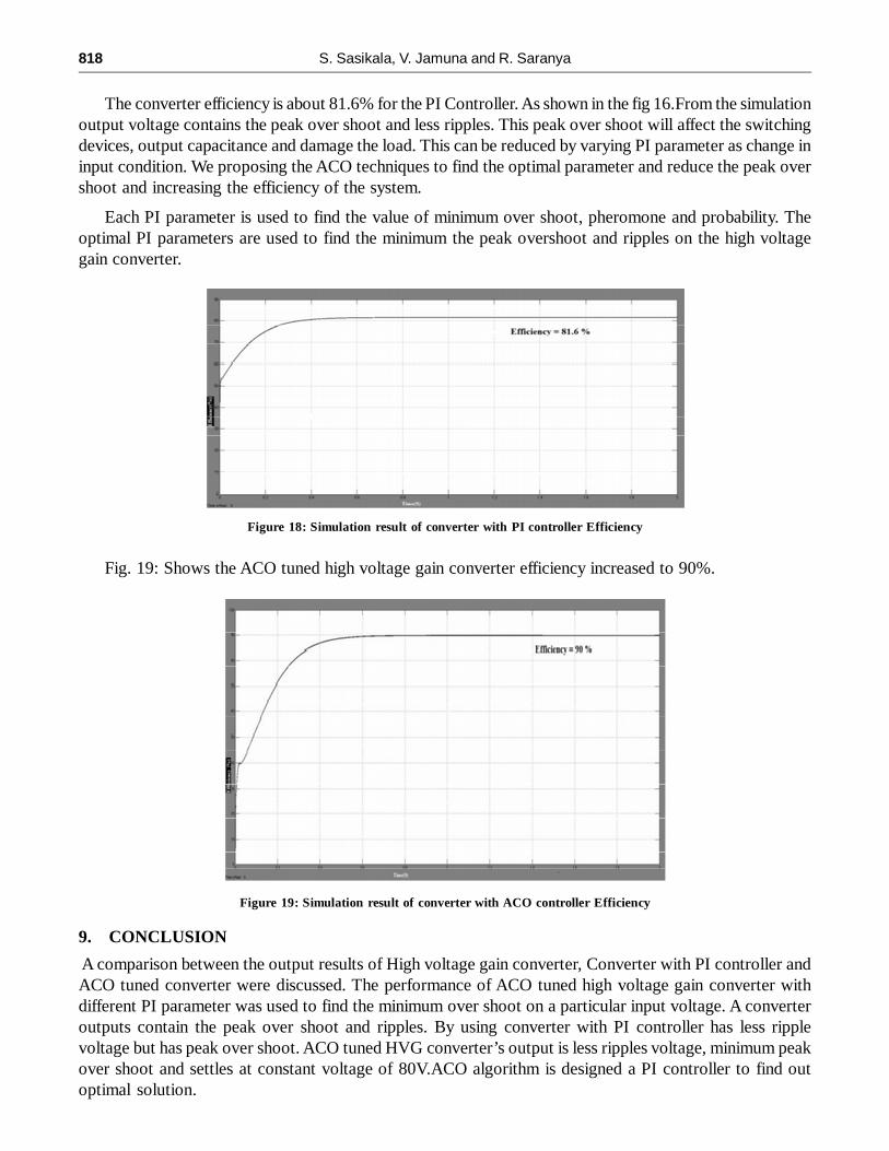
The converter efficiency is about 81.6% for the PI Controller. As shown in the fig 16.From the simulationoutput voltage contains the peak over shoot and less ripples. This peak over shoot will affect the switchingdevices, output capacitance and damage the load. This can be reduced by varying PI parameter as change ininput condition. We proposing the ACO techniques to find the optimal parameter and reduce the peak overshoot and increasing the efficiency of the system.
Each PI parameter is used to find the value of minimum over shoot, pheromone and probability. Theoptimal PI parameters are used to find the minimum the peak overshoot and ripples on the high voltagegain converter.
Figure 18: Simulation result of converter with PI controller Efficiency
Fig. 19: Shows the ACO tuned high voltage gain converter efficiency increased to 90%.
Figure 19: Simulation result of converter with ACO controller Efficiency
9. CONCLUSION
A comparison between the output results of High voltage gain converter, Converter with PI controller andACO tuned converter were discussed. The performance of ACO tuned high voltage gain converter withdifferent PI parameter was used to find the minimum over shoot on a particular input voltage. A converteroutputs contain the peak over shoot and ripples. By using converter with PI controller has less ripplevoltage but has peak over shoot. ACO tuned HVG converter’s output is less ripples voltage, minimum peakover shoot and settles at constant voltage of 80V.ACO algorithm is designed a PI controller to find outoptimal solution.
Implementation of ACO Techniques in High Voltage Gain Converter for SPV System... 819
REFERENCE[1] Mahendran. G and Kandaswamy.K. V. “Ant Colony Optimized Tuned DC-DC Converter,” Int Journal of Computer
Applications (0975 – 8887) ., ICIIIOSP-2013.
[2] K. I. Hwu,and W. Z. Jiang “Voltage Gain Enhancement for A Step-Up Converter Constructed By Ky And Buck-BoostConverters,” IEEE Transaction on Industrial Electronics, Vol 61,No. 4,Apr 2014.
[3] R. W. Erickson and D. Maksimovic, Fundamentals of Power Electronics,2nd ed. Norwell, MA, USA: Kluwer, 2001.
[4] A. I. Pressman, Switching Power Supply Design, 2nd ed. New York, NY, USA: McGraw-Hill, 1998.
[5] K. I. Hwu, K. W. Huang, and W. C. Tu, “Step-up converter combining KY and buck-boost converters,” IET Electron.Lett., vol. 47, no. 12, pp. 722–724, Jun. 2011.
[6] R. J. Wai and R. Y. Duan, “High-efficiency power conversion for low power fuel cell generation system,” IEEE Trans.Power Electron., vol. 20,no. 4, pp. 847–856, Jul. 2005.
[7] C. T. Pan and C. M. Lai, “A high-efficiency high step-up converter with low switch voltage stress for fuel-cell systemapplications,” IEEE Trans.Ind. Electron., vol. 57, no. 6, pp. 1998–2006, Jun. 2010.
[8] Sweta Srivastav, Sanjay Singh., “An Introduction To Sepic Converters”, International Referred Research Journal,July,2011.
[9] Brahim Berbaoui. Chellali Benachaiba. Mustapha Rahli. Hamza tedjini, “An efficient algorithm to tuning PI-controllerparameters for shunt active power filter using ant colony optimization”, Przegl¹d Elektrotechniczny (Electrical Review),Issn 0033-2097, 2011.
[10] Hong He. Fang Liu. Li Li. Jin-Rong Yang. Lei Su. Yi Wu. “Study of PID Control System For Ant Colony Algorithm”IEEE, 2009.
[11] Michael Brand. Michael Masuda. Nicole Wehner. Xiao-Hua Yu .2010, “Ant Colony Optimization Algorithm for RobotPath Planning”, International Conference On Computer Design And Appliations, 2010.
[12] W. Li,W. Li, X. He, D. Xu, and B.Wu, “General derivation law of nonisolated high-step-up interleaved converters withbuilt-in transformer,” IEEE Trans. Ind. Electron., vol. 59, no. 3, pp. 1650–1661, Mar. 2012.