Implementation of An Automatic Fingerprint Identification System Peihao Huang, Chia-Yung Chang, Chaur-Chi n Chen Department of Computer Science National Tsing Hua University Hsinchu, Taiwan 30013 E-mail: [email protected]
Transcript
Implementation of An Automatic Fingerprint Identification System
Peihao Huang, Chia-Yung Chang, Chaur-Chin ChenDepartment of Computer Science
National Tsing Hua UniversityHsinchu, Taiwan 30013
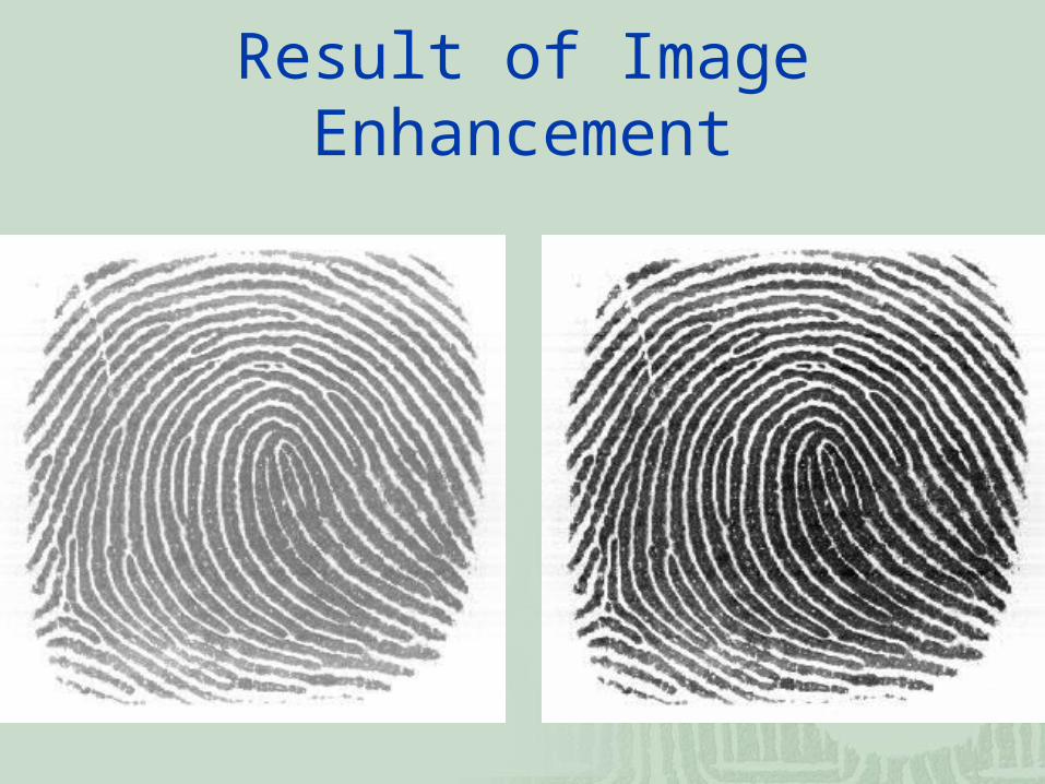
The moisture and scars of a finger as well as the pressure due to a fingerprint sensing could distort the quality of the acquired fingerprint image.
We adopt an ad hoc strategy to enhance the quality of a fingerprint image.
Support that A (i, j) is image gray level at pixel (i, j), μ and s2 are the mean and variance of gray levels of input image, and α=150, γ=95, γ must satisfy γ>s.
The enhanced image B( i , j ) is given as follows.
B( i , j ) α + γ * ([A ( i , j ) – μ] / s)
Result of Image Enhancement
Orientation Computation(1)
First we apply a 5 by 5 median filtering on the image to avoid false gradient vectors generated by noise.
Then compute the gradient (Gx,Gy) at each pixel by a Sobel operator.
mask Sobel Operation
)2()2(
)2()2(
741963
321987
zzzzzzG
zzzzzzG
y
x
z1 z2 z3
z4 z5 z6
z7 z8 z9
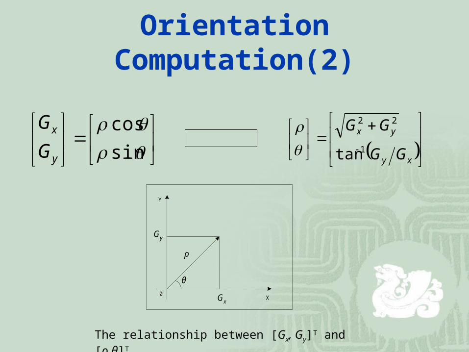
Orientation Computation(2)
sin
cos
y
x
G
G
xy
yx
GG
GG
1
22
tan
0 GxX
Y
Gy
ρ
θ
The relationship between [Gx, Gy]T and [ρ,θ]T
Orientation Computation(3)
Because of opposite gradient vectors might offset each other, we double the angles of the gradient vectors before averaging each block, and let the length of the gradient vectors be squared.
Let be represented by
The average gradient in each block R (w×w) is
Tyx ,
yx
yx
y
x
GG
GG
2cossin2
sincos
2sin
2cos 22
2
222
2
2
Tyx ~,~
yx
yx
Ry
x
Ry
x
GG
GG
2w
1
w
1~
~ 22
22
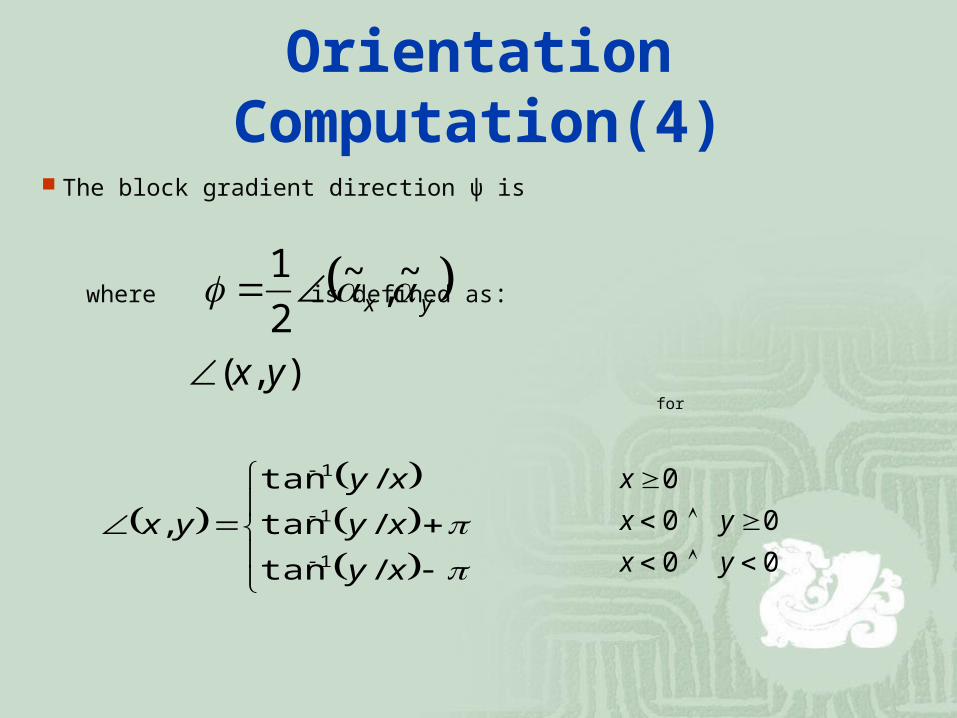
Orientation Computation(4)
The block gradient direction ψ is
where is defined as:
for
yx ~,~2
1
),( yx
xy
xy
xy
yx
/tan
/tan
/tan
,1
1
1
0 0
0 0
0
yx
yx
x
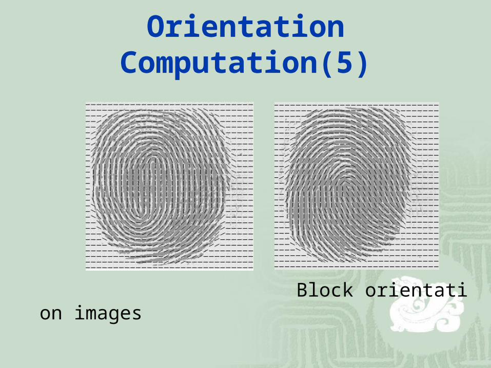
Orientation Computation(5)
Block orientation images
Region of Interest Detection(1)
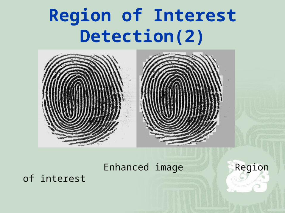
To avoid obtaining false singular points or minutiae, we use mean and standard deviation in each block to determine if the block is “good” (not a marginal block) or not.
where , and is the ratio of distance to the center of the fingerprint image. μ and σ are normalized
to be in [0,1]. If v > 0.8, the block is what we want.
210 ww)1(w v
2w5.0w 0 5.0w1
Region of Interest Detection(2)
Enhanced image Region of interest
Singular Point Detection(1)
Because of noisy directions, we have to smooth the direction before computing the Poincaré index.
We regard the direction as a vector, double the angles and use a 3 by 3 averaging filter to smooth the direction.
The average direction of the block is
ciiBBB
BBb
BBa
yixii
i ycyi
i xcxi
or 70 ,,
2
2
,,
7
0 ,,
7
0 ,,B3 B2 B1
B4 Bc B0
B5 B6 B7
1 1 1
1 2 1
1 1 1
a
barctan
2
1
Singular Point Detection(2)
We compute Poincaré index by summing up the difference in the direction surrounding the block P. For each block Pj, we compute the angle difference from 8 neighboring blocks along counter-clockwise direction.
P1 P8 P7
P2 P P6
P3 P4 P5
P1 → P2 → P3 → P4 → P5 → P6 → P7 → P8 → P1
Core if the sum of difference is 180°
Delta if the sum of difference is -180°
Singular Point Detection(3)
Singular points of Fingerprint Images
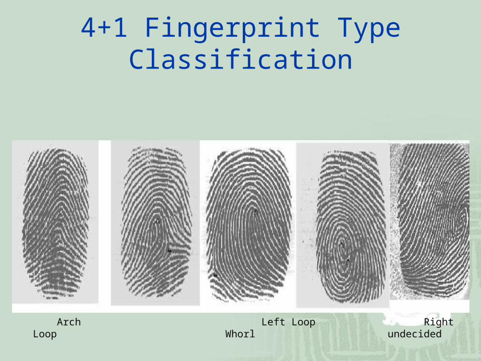
4+1 Fingerprint Type Classification
Arch Left Loop Right Loop Whorl undecided
Type Classification
Type Arch
(tented arch)
Left loop
Right loop
Whorl
(twins loop)
Others
# of cores
0 or 1 1 1 2 0 or >2
# of deltas
0 or 1
(middle)
1(right) 1(left) 0~2 0 or >2
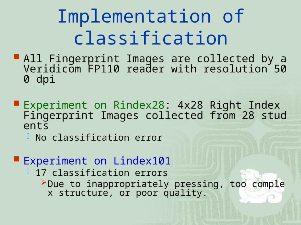
Implementation of classification
All Fingerprint Images are collected by a Veridicom FP110 reader with resolution 500 dpi
Experiment on Rindex28: 4x28 Right Index Fingerprint Images collected from 28 students No classification error
Experiment on Lindex101 17 classification errors
Due to inappropriately pressing, too complex structure, or poor quality.
Inappropriately Pressing
Whorl Left Loop
Inappropriately Pressing
Right Loop Arch
Too Complex Structure
Left or Whorl Left or Arch
Fingerprint Images of Poor Quality
? X ? X
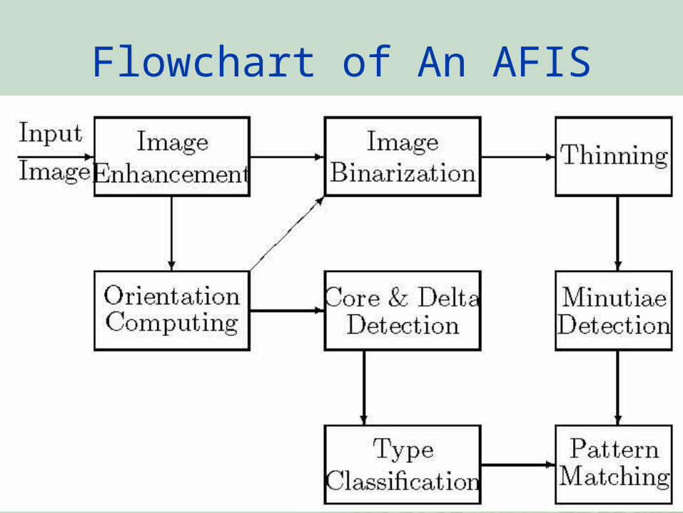
Flowchart of An AFIS
Image Binarization(1)
We have to distinguish valley and ridge of a fingerprint image before smoothing and thinning. So the gray value of pixels in the enhanced fingerprint image will be binarized to 0 or 255.
First we compute the gray value of P25 and P50 from the enhanced image, where Pk is the kth percentile of enhanced fingerprint image histogram.
Then we partition an enhanced fingerprint image into w by w blocks and compute the mean of each blocks. We define that Mj is the mean of the j-th block.
Image Binarization(2)
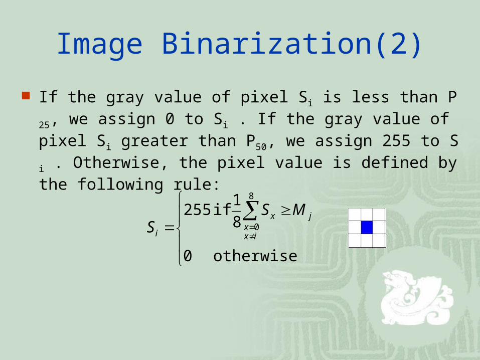
If the gray value of pixel Si is less than P25, we assign 0 to Si . If the gray value of pixel Si greater than P50, we assign 255 to Si . Otherwise, the pixel value is defined by the following rule:
otherwise 0
8
1 if 255
8
0j
ixx
x
i
MSS
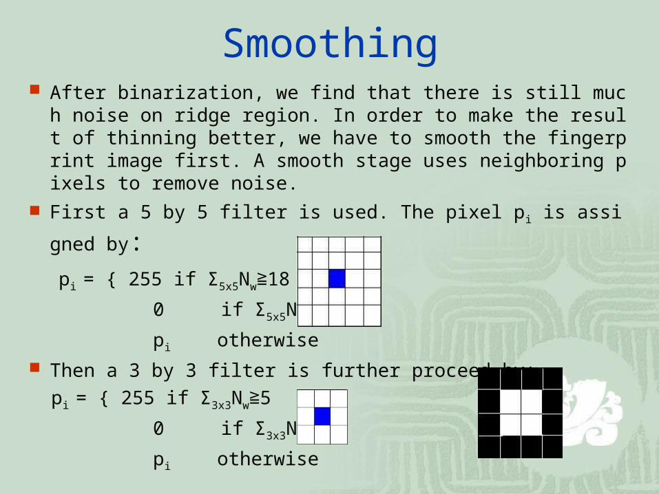
Smoothing After binarization, we find that there is still much noise on ri
dge region. In order to make the result of thinning better, we have to smooth the fingerprint image first. A smooth stage uses neighboring pixels to remove noise.
First a 5 by 5 filter is used. The pixel pi is assigned by:
pi = { 255 if Σ5x5Nw 18≧ 0 if Σ5x5Nb 18 ≧ pi otherwise
Then a 3 by 3 filter is further proceed by:
pi = { 255 if Σ3x3Nw 5≧ 0 if Σ3x3Nb 5 ≧ pi otherwise
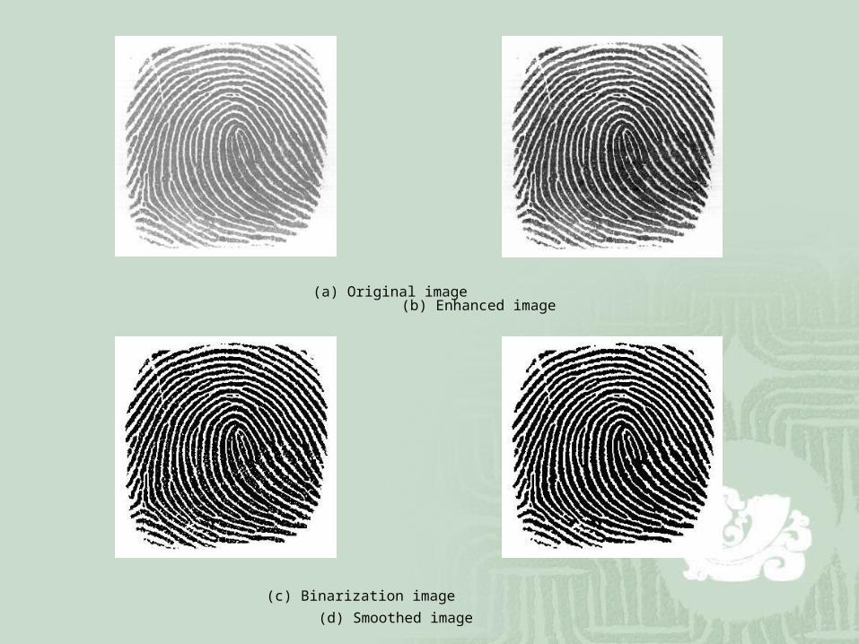
(a) Original image (b) Enhanced image
(c) Binarization image (d) Smoothed image
Thinning
The purpose of thinning stage is to gain the skeleton structure of fingerprint image.
It reduces a binary image consisting of ridges and valleys into a ridge map of unit width.
(d) Smoothed image (e) Thinned image
Minutiae Detection
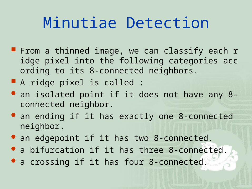
From a thinned image, we can classify each ridge pixel into the following categories according to its 8-connected neighbors.
A ridge pixel is called : an isolated point if it does not have any 8-connected neigh
bor. an ending if it has exactly one 8-connected neighbor. an edgepoint if it has two 8-connected. a bifurcation if it has three 8-connected. a crossing if it has four 8-connected.
Minutiae Extraction
Due to broken ridges, fur effects, and ridge endings near the margins of an image, we have to remove the spurious minutiae as described below.
(1) Two endings are too close (within 8 pixels)
(2) An ending and a bifurcation are too close (< 8 pixels)
(3) Two bifurcations are too close (< 8 pixels)
(4) Minutiae are near the margins (< 8 pixels)
Minutiae Extraction
Spurious minutia pixels include :
(a) Ending that lie on the margins of the region of interest.
(b) Two nearest endings with the same ridge orientation.
(c) ending and bifurcation that are connected and close enough.
(d) two bifurcations that are too close.
Example of Minutiae Extraction
Example of Minutiae Extraction
Example of Minutiae Extraction
Minutiae Extraction (10)
Fingerprint Template Data
The information format of fingerprint template data.
The information format of singular points, core or delta.
The information format of a minutia.
Type #of cores
Core* # of deltas Delta* # of minutiae
Minutiae*
4 bits 2 bits 24 bits 2 bits 24 bits
7 bits 26 bits
X Coordinate Y Coordinate Direction
10 bits 10 bits 4 bits
Kind of Minutiae X Coordinate Y Coordinate Direction
2 bits 10 bits 10 bits 4 bits
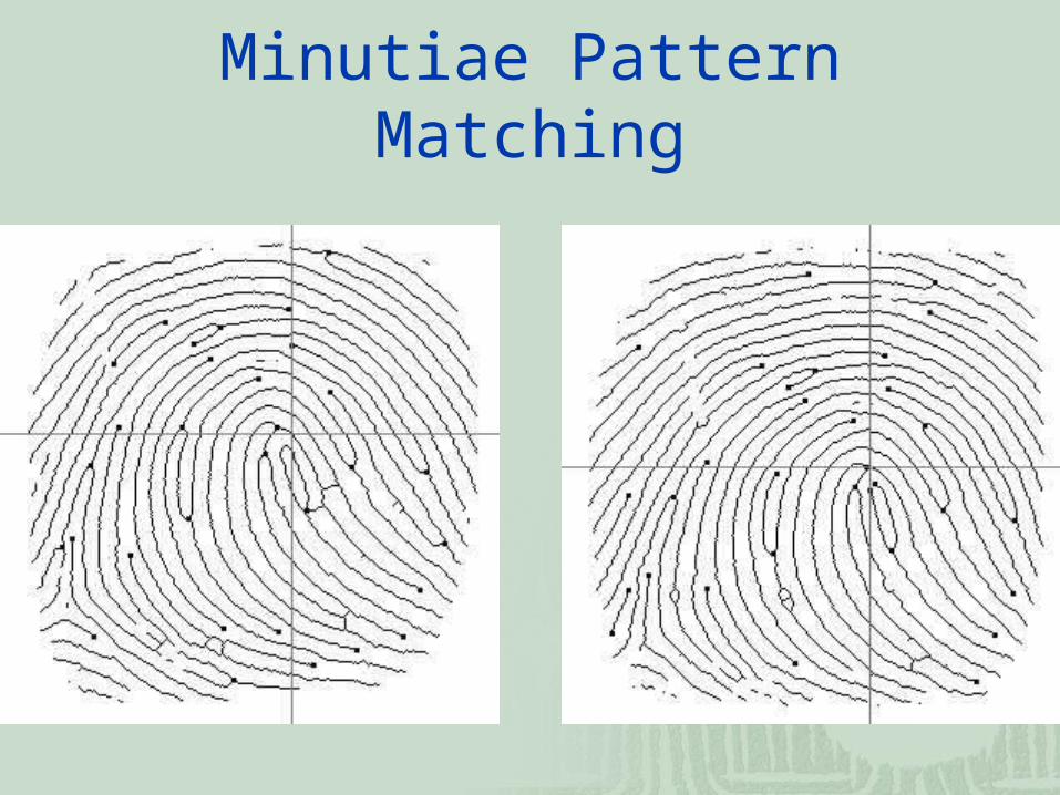
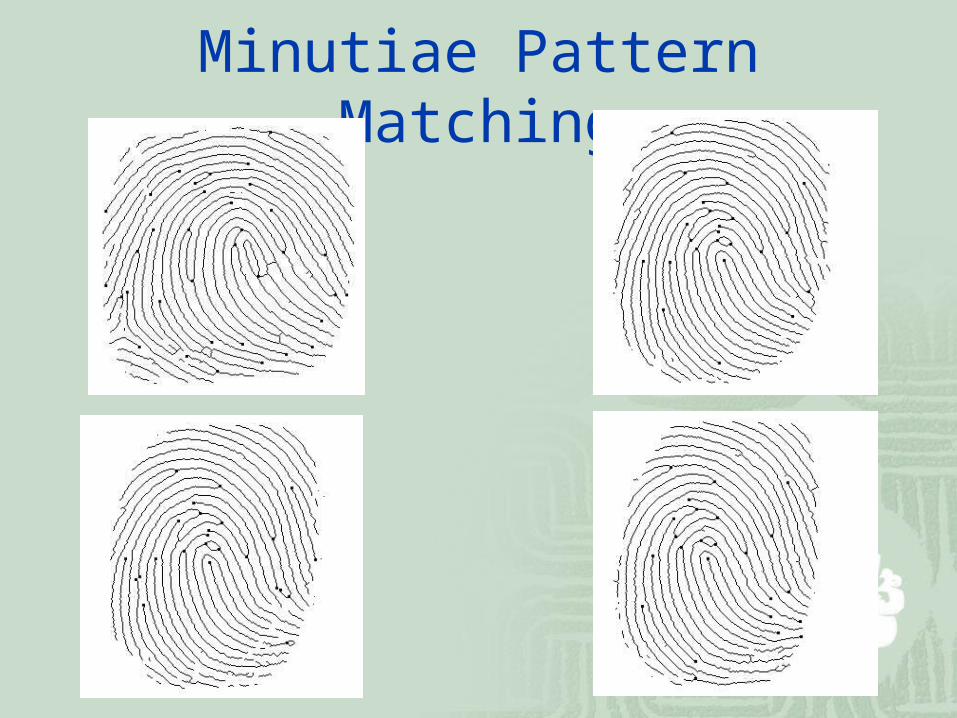
Minutiae Matching
Minutiae Pattern Matching
Minutiae Pattern Matching
Fingerprint Matching Score
The matching score of these two fingerprints is calculated by
where M is the number of potential type-matching minutiae within a disk of a certain user-specified radius, R (about 8~16 pixels). r measures the distance between a pair of potentially matched minutiae points.
j
M
j R
r
MS
1
)1(1
100
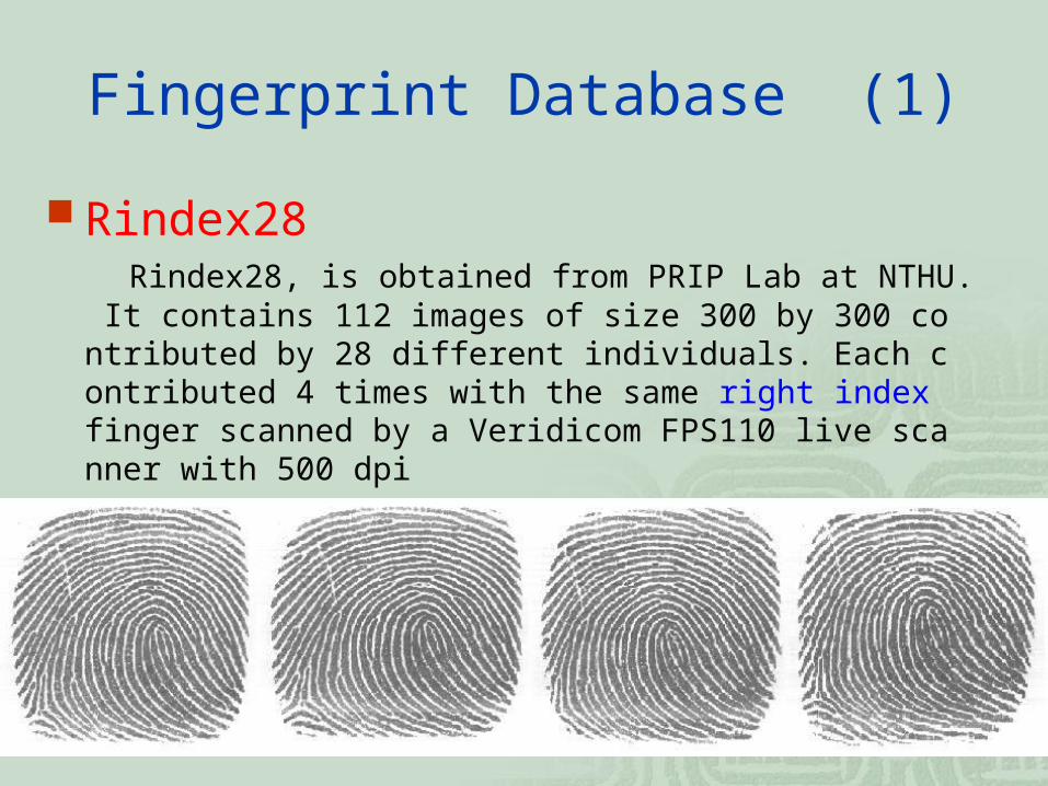
Fingerprint Database (1)
Rindex28 Rindex28, is obtained from PRIP Lab at NTHU. It contains 11
2 images of size 300 by 300 contributed by 28 different individuals. Each contributed 4 times with the same right index finger scanned by a Veridicom FPS110 live scanner with 500 dpi
Fingerprint Database (2)
Lindex101 Lindex101, is obtained from PRIP Lab at NTHU. It contains 40
4 images of size 300 by 300 contributed by 101 different individuals. Each contributed 4 times with the same left index finger scanned by a Veridicom FPS110 live scanner with 500 dpi
Fingerprint Database (3)
FVC2000
Sensor Type Image Size Resolution
DB1 Low-cost Optical Sensor 300x300 500 dpi
DB2 Low-cost Capacitive Sensor
256x364 500 dpi
DB3 Optical Sensor 448x478 500 dpi
DB4 Synthetic Generator 240x320 about500 dpi
Fingerprint Database (4)
Examples of fingerprint images from each database of FVC2000
Fingerprint has been used as an individual identification for more than a century.
A perfect automatic fingerprint matching system has not been discovered yet.
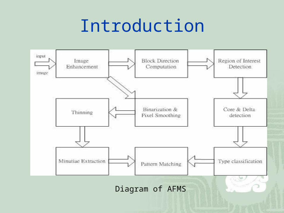
We attempt to develop a sequence of algorithms to achieve an AFMS.
Introduction
Diagram of AFMS
Fingerprint Classification (1)
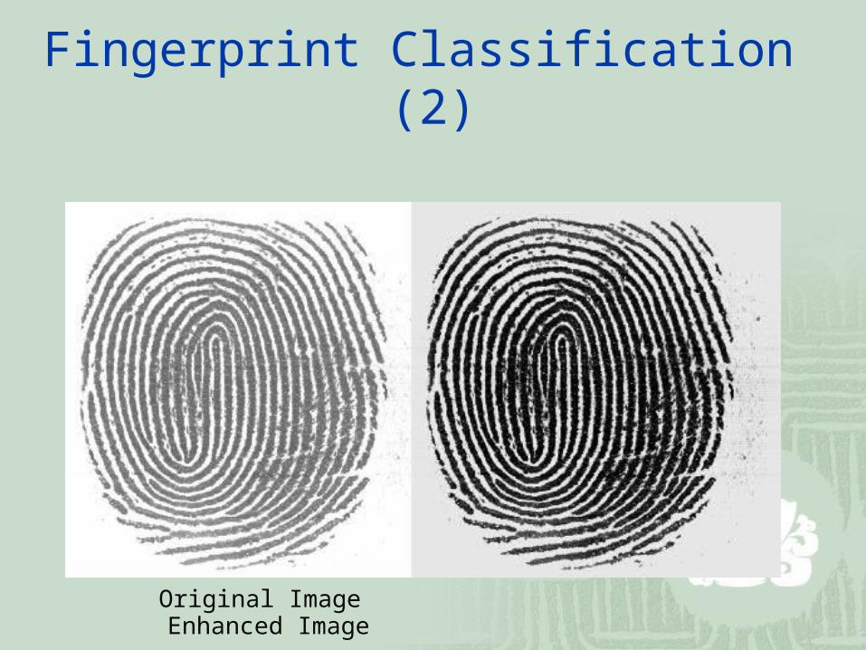
Image Enhancement we adopt the following transformation to stretch the
distribution of gray levels.
μ is the mean of gray levels of input image.
α=150, γ=100.
σ is the standard deviation of gray level of input image
)/]),(([*),( jiAjiB
Fingerprint Classification (2)
Original Image Enhanced Image
Fingerprint Classification (3)
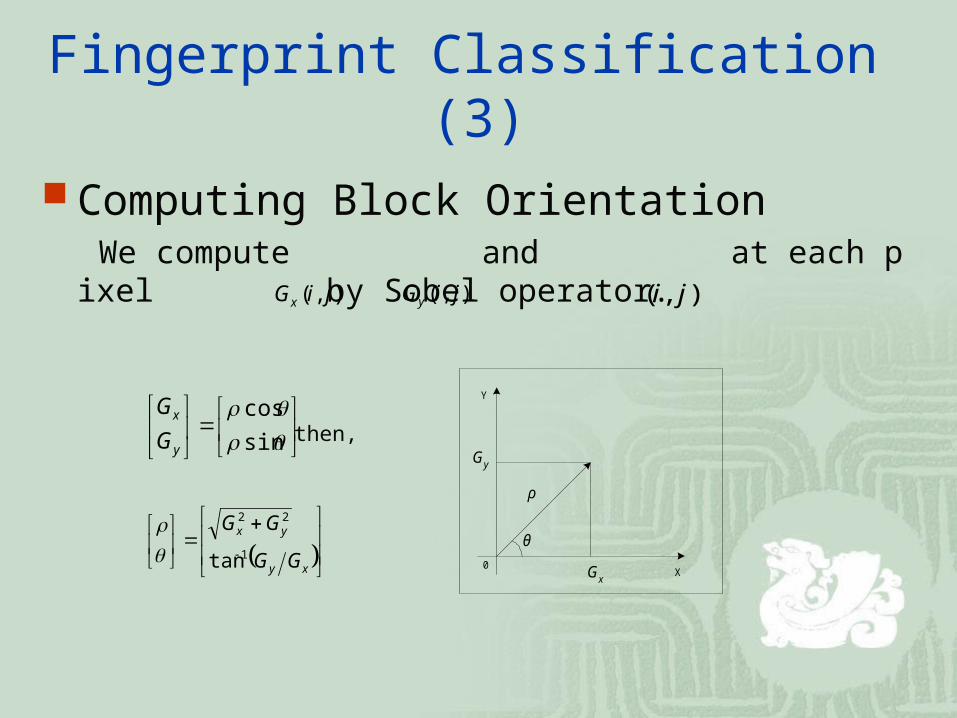
Computing Block Orientation We compute and at each pixel by Sobel op
erator. ),( jiGx ),( jiGy ),( ji
sin
cos
y
x
G
Gthen,
xy
yx
GG
GG
1
22
tan
0 GxX
Y
Gy
ρ
θ
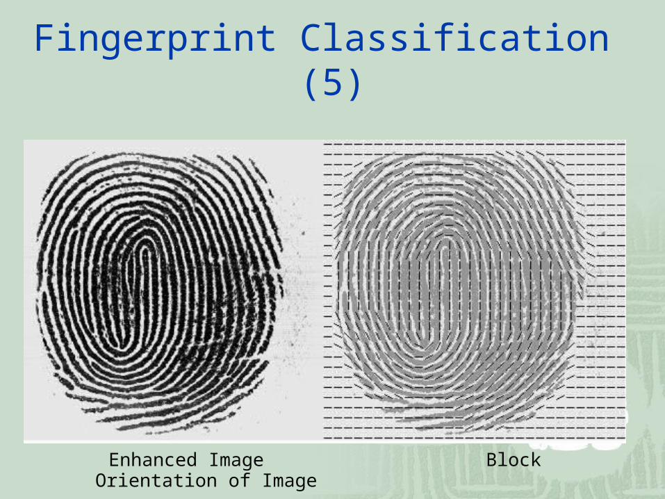
Fingerprint Classification (4)
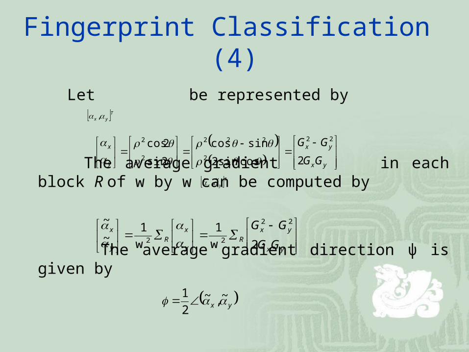
Let be represented by
The average gradient in each block R of w by w can be computed by
The average gradient direction ψ is given by
yx
yx
y
x
GG
GG
2cossin2
sincos
2sin
2cos 22
2
222
2
2
yx
yx
Ry
x
Ry
x
GG
GG
2w
1
w
1~
~ 22
22
yx ~,~2
1
Tyx ,
Tyx ~,~
Fingerprint Classification (5)
Enhanced Image Block Orientation of Image
Fingerprint Classification (6)
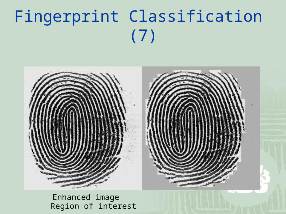
Region of Interest (RoI) Detection In order to avoid detecting false singular points or minutiae We can us
e the mean and standard deviation in each block to decide if the block is of interest or not
We assign and . is the percentage of distance to the center of a fingerprint image.
The meanμand the standard deviationσare normalized to be in [0,1]
The block is of interest if v > 0.5.
210 ww)1(w v
5.0w0 5.0w1 2w
Fingerprint Classification (7)
Enhanced image Region of interest
Fingerprint Classification (8)
Singular Point Detection Due to the unavoidable noisy directions, we smooth the direction befor
e computing the Poincaré index We regard the direction as a vector, double the angles by using a 3 by
3 averaging box filter to smooth the direction.
The average direction of the block is defined as
a
barctan
2
1
ciiBBB
BBb
BBa
yixii
i ycyi
i xcxi
or 70 ,,
2
2
,,
7
0 ,,
7
0 ,,
B3 B2 B1
B4 Bc B0
B5 B6 B7
1 1 1
1 2 1
1 1 1
Fingerprint Classification (9)
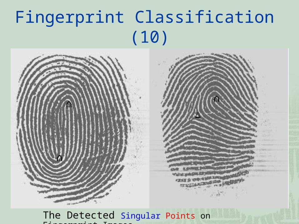
We compute the Poincaré index by summing up the changes along the direction surrounding the block P. For each block P j, we compute the angle difference from 8 neighboring blocks along counter-clockwise direction.
P1 P8 P7
P2 P P6
P3 P4 P5
Core if the sum of difference is 180°
Delta if the sum of difference is -180°
P1 → P2 → P3 → P4 → P5 → P6 → P7 → P8 → P1
Fingerprint Classification (10)
The Detected Singular Points on Fingerprint Images
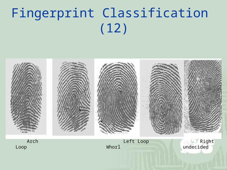
Fingerprint Classification (11)
typearch
(tented arch)left loop right loop
Whorl(twins loop)
others
# of cores 0 or 1 1 1 2 0 or >2
# of deltas
0 or 1 (middle)
1 (right) 1 (left) 0 ~ 2 0 or >2
Criteria for the types of fingerprints
Fingerprint Classification (12)
Arch Left Loop Right Loop Whorl undecided
Minutiae Extraction (1)
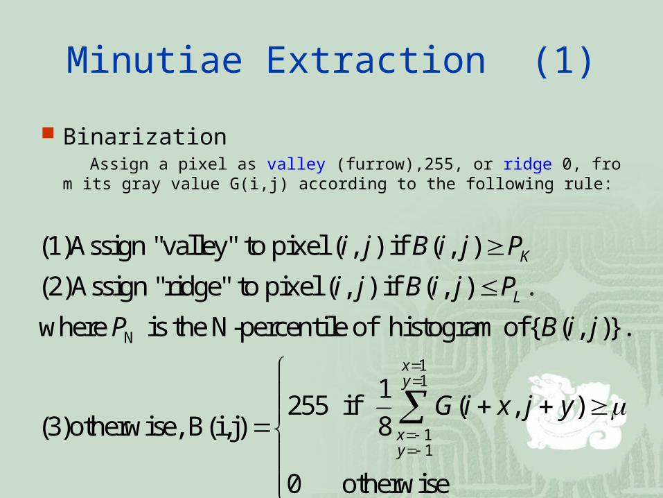
Binarization Assign a pixel as valley (furrow),255, or ridge 0, from its gray value
G(i,j) according to the following rule:
N
1
11
(1)Assign "valley" to pixel ( , ) if ( , )
(2)Assign "ridge" to pixel ( , ) if ( , ) .
where is the N-percentile of histogram of{ ( , )}.
1255 if ( , )
8(3)otherwise, B(i,j)
K
L
xy
xy
i j B i j P
i j B i j P
P B i j
G i x j y
1
0 otherwise
Minutiae Extraction (2)
Enhanced image Binarized image
Minutiae Extraction (3)
Smoothing In order to make the result of thinning better, we might
further smooth the fingerprint image by filtering.
First a 5 by 5 filter is used. The pixel is assigned by:
Then a 3 by 3 filter is further proceeded by:
otherwise
18 if 0
18 if 255
55
55
i
b
w
i
p
N
N
p
ip
otherwise
5 if 0
5 if 255
33
33
i
b
w
i
p
N
N
p
Minutiae Extraction (4)
Binarized image Smoothed image
Minutiae Extraction (5)
Thinning The purpose of thinning is to gain the skeleton structure of f
ingerprint image. The ridge is thinned to unit width for minutiae extraction. We use a thinning algorithm based on Hilditch (Suen+Wang, Pavalidis) to preserve the connectedness and shape of the fingerprint image.
Minutiae Extraction (6)
Smoothed image Thinning image.
Minutiae Extraction (7)
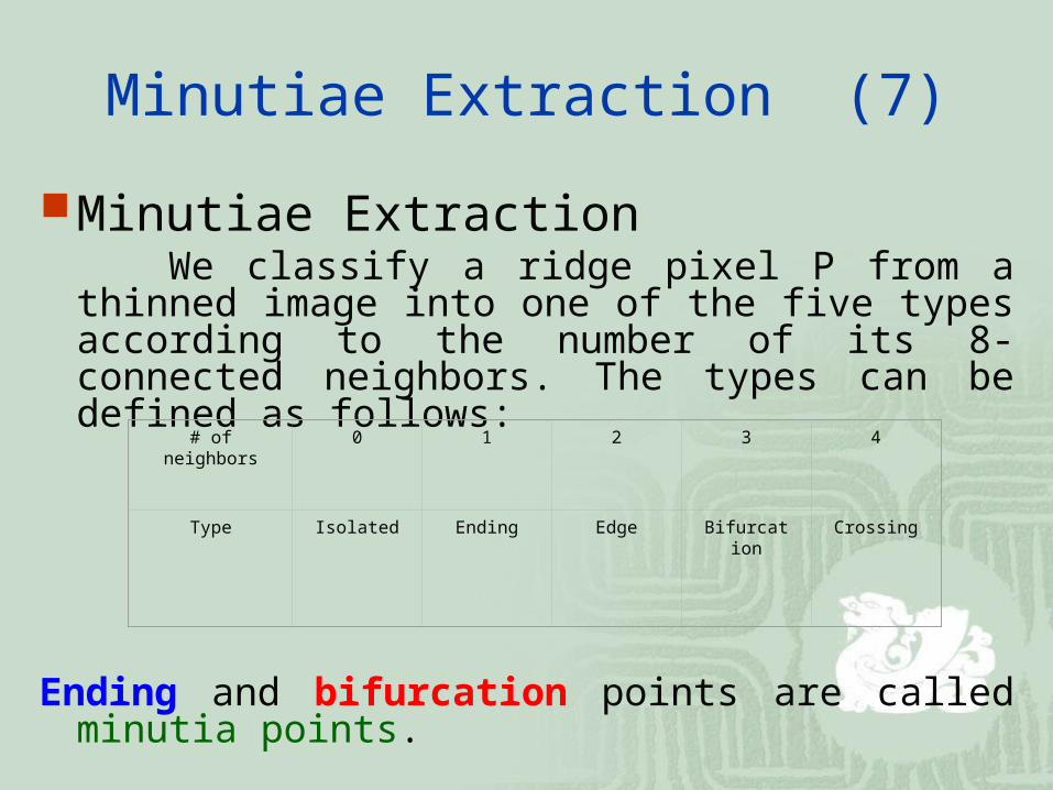
Minutiae Extraction We classify a ridge pixel P from a thinned image
into one of the five types according to the number of its 8-connected neighbors. The types can be defined as follows:
Ending and bifurcation points are called minutia points.
# of neighbors 0 1 2 3 4
Type Isolated Ending Edge Bifurcation Crossing
Minutiae Extraction (8)
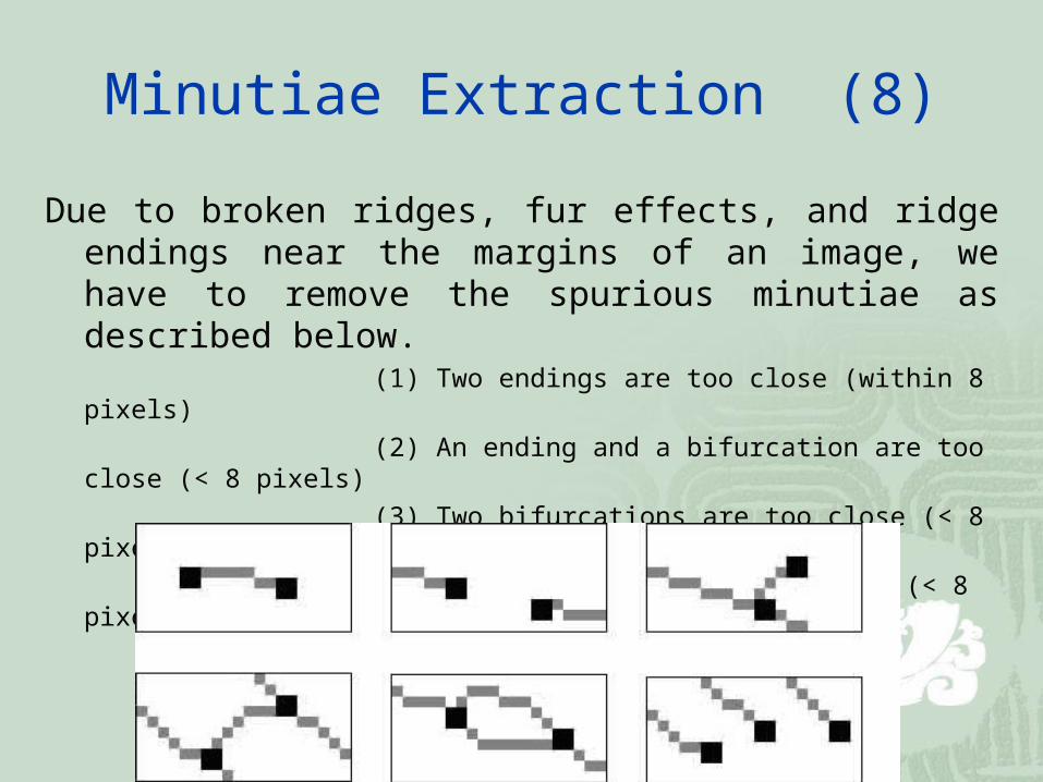
Due to broken ridges, fur effects, and ridge endings near the margins of an image, we have to remove the spurious minutiae as described below.
(1) Two endings are too close (within 8 pixels)
(2) An ending and a bifurcation are too close (< 8 pixels)
(3) Two bifurcations are too close (< 8 pixels)
(4) Minutiae are near the margins (< 8 pixels)
Minutiae Extraction (9)
Thinning image Minutiae points after removingspurious minutiae
Minutiae Extraction (10)
Fingerprint Template Data
The information format of fingerprint template data.
The information format of singular points, core or delta.
The information format of a minutia.
Type #of cores
Core* # of deltas Delta* # of minutiae
Minutiae*
4 bits 2 bits 24 bits 2 bits 24 bits
7 bits 26 bits
X Coordinate Y Coordinate Direction
10 bits 10 bits 4 bits
Kind of Minutiae X Coordinate Y Coordinate Direction
2 bits 10 bits 10 bits 4 bits
Fingerprint Matching (1)
Registration Point The registration point is regarded as the origin when
processing minutiae matching. Left Loop and Right Loop: its core is employed Whorl: the coordinate of the upper-row core is utilized Arch: we apply the mask shown as follows
_
/ _ \
Fingerprint Matching (2)
Minutiae MatchingThere are four steps involved in our matching process:
(1) Check the type of fingerprint
(2) Overlay by registration point
(3) Rotate and relocate
(4) Compute the matching score
(5) Comparison (the larger match score, the better match)
Fingerprint Matching (3)
The matching score of these two fingerprints is calculated by
where M is the number of potential type-matching minutiae within a disk of a certain user-specified radius, R (about 8~16 pixels). r measures the distance between a pair of potentially matched minutia points.
j
M
j R
r
MS
1
)1(1
100
Fingerprint Database (1)
Rindex28 Rindex28, is obtained from PRIP Lab at NTHU. It contains 11
2 images of size 300 by 300 contributed by 28 different individuals. Each contributed 4 times with the same right index finger scanned by a Veridicom FPS110 live scanner with 500 dpi
Fingerprint Database (2)
Lindex101 Lindex101, is obtained from PRIP Lab at NTHU. It contains 40
4 images of size 300 by 300 contributed by 101 different individuals. Each contributed 4 times with the same left index finger scanned by a Veridicom FPS110 live scanner with 500 dpi
Fingerprint Database (3)
FVC2000
Sensor Type Image Size Resolution
DB1 Low-cost Optical Sensor 300x300 500 dpi
DB2 Low-cost Capacitive Sensor
256x364 500 dpi
DB3 Optical Sensor 448x478 500 dpi
DB4 Synthetic Generator 240x320 about500 dpi
Fingerprint Database (4)
Examples of fingerprint images from each database of FVC2000