Page 1
University of Montana University of Montana
ScholarWorks at University of Montana ScholarWorks at University of Montana
Graduate Student Theses, Dissertations, & Professional Papers Graduate School
2008
Implementation of an XML-based user interface with applications Implementation of an XML-based user interface with applications
in ice sheet modeling in ice sheet modeling
Daniel Ross Lande The University of Montana
Follow this and additional works at: https://scholarworks.umt.edu/etd
Let us know how access to this document benefits you.
Recommended Citation Recommended Citation Lande, Daniel Ross, "Implementation of an XML-based user interface with applications in ice sheet modeling" (2008). Graduate Student Theses, Dissertations, & Professional Papers. 554. https://scholarworks.umt.edu/etd/554
This Thesis is brought to you for free and open access by the Graduate School at ScholarWorks at University of Montana. It has been accepted for inclusion in Graduate Student Theses, Dissertations, & Professional Papers by an authorized administrator of ScholarWorks at University of Montana. For more information, please contact [email protected] .
Page 2
(i)
IMPLEMENTATION OF AN XML-BASED USER INTERFACE WITH APPLICATIONS IN
ICE SHEET MODELING
By
Daniel Ross Lande
B.S. Computer Science, The University of Montana, Missoula, Montana, 2005
Thesis
presented in partial fulfillment of the requirements
for the degree of
Master of Science
in Computer Science
The University of Montana
Missoula, MT
Fall 2008
Approved by:
Dr. David A. Strobel, Dean
Graduate School
Dr. Joel Henry, Chair
Department of Computer Science
Dr. Jesse Johnson
Department of Computer Science
Dr. Jeff Shay
Department of Management & Marketing
Page 3
(i)
Lande, Daniel, M.S., December 2008 Computer Science
Implementation of an XML-based user interface with applications in ice sheet model-
ing
Chairperson: Dr. Joel Henry
The scientific domain presents unique challenges to software developers. This thesis
describes the application of design patterns to the problem of dynamically changing
interfaces to scientific application software (GLIMMER, which performs ice sheet
modeling). In its present form, GLIMMER uses a text configuration file to define
model behavior, set parameters, and structure model input/output (I/O). The creation
of the configuration file presents a significant problem to users due to its format and
complexity. GLIMMER is still under development, and the number of changes to
configuration parameters, parameter types, and parameter dependencies makes devel-
opment of any single interface of use only for a short term. The application of design
patterns described here resulted in an interface specification tool that then generates
multiple versions of a user interface usable across a wide variety of configuration pa-
rameter types, values, and dependencies. The resulting products have leveraged de-
sign patterns and solved problems associated with design pattern usage not found in
the specialized software engineering literature.
Page 4
(ii)
ACKNOWLEDGMENTS
I would like to take this opportunity to thank those who have helped me with this
thesis and my graduate studies. To my wife Lindsay, who supports me in all aspects
of life and allows me to achieve my goals and aspirations through her love and sup-
port. To my family, for helping me in all the ways they do and always encouraging
me to strive for greater things. To Dr. Joel Henry, a mentor and advisor who I can
always count on. To Dr. Jesse Johnson, for stimulating my scientific mind and allow-
ing me to work on this project. To Dr. Jeff Shay, for encouraging my curiosity in
business and “spinning” me into shape. And, thanks to the countless others who have
helped me along the way.
Page 5
(iii)
TABLE OF CONTENTS
Acknowledgments .................................................................................................... ii
Table of Contents .................................................................................................... iii
List of Figures .......................................................................................................... v
Chapter 1 Introduction ...................................................................................... 1.1
1.1 Introduction ............................................................................................. 1.1
1.2 Motivation ............................................................................................... 1.2
1.3 Background .............................................................................................. 1.3
1.4 Goal ......................................................................................................... 1.4
1.5 Thesis Organization ................................................................................. 1.5
Chapter 2 Requirements .................................................................................... 2.7
2.1 Requirements Analysis ............................................................................. 2.7
2.2 Requirements Specification ...................................................................... 2.9
Chapter 3 Design .............................................................................................. 3.10
3.1 Overview ............................................................................................... 3.10
3.2 Element Structure ................................................................................... 3.15
3.2.1 Elements ................................................................................... 3.18
3.2.2 Rules ......................................................................................... 3.27
3.2.3 Logic......................................................................................... 3.32
3.2.4 Other Classes ............................................................................ 3.32
3.3 Interface Specification Tool ................................................................... 3.35
3.4 Interface Presentation Tools ................................................................... 3.39
3.4.1 ISIS ........................................................................................... 3.39
3.4.2 ISIS Educational Version .......................................................... 3.40
Chapter 4 Implementation .............................................................................. 4.42
4.1 Implementation Strategy ........................................................................ 4.42
4.2 Element Structure Implementation ......................................................... 4.43
4.3 Interface Specification Implementation .................................................. 4.43
4.4 Interface Presentation Implementation.................................................... 4.44
4.5 Distributables ......................................................................................... 4.46
Chapter 5 Testing............................................................................................. 5.48
5.1 Testing Strategy ..................................................................................... 5.48
Chapter 6 Results ............................................................................................. 6.50
6.1 ISIS XML Creator .................................................................................. 6.50
6.2 ISIS ........................................................................................................ 6.53
6.3 ISIS Educational Version ....................................................................... 6.60
Chapter 7 Future Directions............................................................................ 7.63
7.1 Next Generation Functionality ............................................................... 7.63
7.2 Extensibility of Design ........................................................................... 7.64
Chapter 8 Conclusion ...................................................................................... 8.68
8.1 Lessons Learned..................................................................................... 8.68
Page 6
(iv)
Chapter 9 References ....................................................................................... 9.70
Appendix A. Compiling GLIMMER for Microsoft Windows ......................... 9.72
Overview ........................................................................................................ 9.72
Prerequisites .................................................................................................... 9.73
Method............................................................................................................ 9.73
Page 7
(v)
LIST OF FIGURES
Figure 1 Example of a simple GLIMMER configuration file ............................... 3.13
Figure 2 Echo Design Diagram ............................................................................ 3.16
Figure 3 Element Inheritance Hierarchy ............................................................... 3.18
Figure 4 ElementRange numeric spinner .............................................................. 3.19
Figure 5 ElementOptions drop-down box ............................................................. 3.20
Figure 6 ElementOptionsExecutable drop-down box ............................................. 3.20
Figure 7 ElementList textbox ............................................................................... 3.20
Figure 8 ElementFileSingleIn textbox and file dialog button ................................ 3.21
Figure 9 File Dialog ............................................................................................. 3.22
Figure 10 ElementFileMultipleIn controls with ElementRange for
specifying time step .......................................................................... 3.23
Figure 11 ElementFileMultipleOut and additional controls .................................. 3.24
Figure 12 ElementParent complete panel ............................................................. 3.25
Figure 13 Tooltip using shortDescription .............................................................. 3.26
Figure 14 Returned value of the writeConfig() method for ElementParent
options .............................................................................................. 3.27
Figure 15 Rules Inheritance Hierarchy ................................................................. 3.28
Figure 16 Use of setLabelColor() to show invalid file path .................................. 3.29
Figure 17 Helper classes and their integration into the design. ............................. 3.33
Figure 18 Scenario Chooser Design Diagram ....................................................... 3.35
Figure 19 ISIS XML Creator design diagram ....................................................... 3.36
Figure 20 Example of an XML file produced by the ISIS XML Creator............... 3.38
Figure 21 ISIS Design Diagram ........................................................................... 3.39
Figure 22 ISIS Educational Version Design ......................................................... 3.40
Figure 23 ISIS XML Creator main screen ............................................................ 6.50
Figure 24 ISIS XML Creator element tree creation ............................................... 6.51
Figure 25 ISIS XML Creator XML file for simple tree with three nodes .............. 6.52
Page 8
(vi)
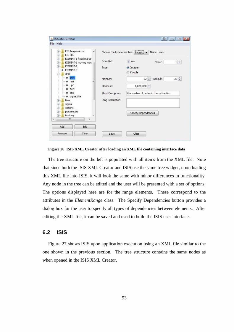
Figure 26 ISIS XML Creator after loading an XML file containing
interface data .................................................................................... 6.53
Figure 27 ISIS main screen .................................................................................. 6.54
Figure 28 ISIS Configuration Tab ........................................................................ 6.55
Figure 29 ISIS Data Validation ............................................................................ 6.56
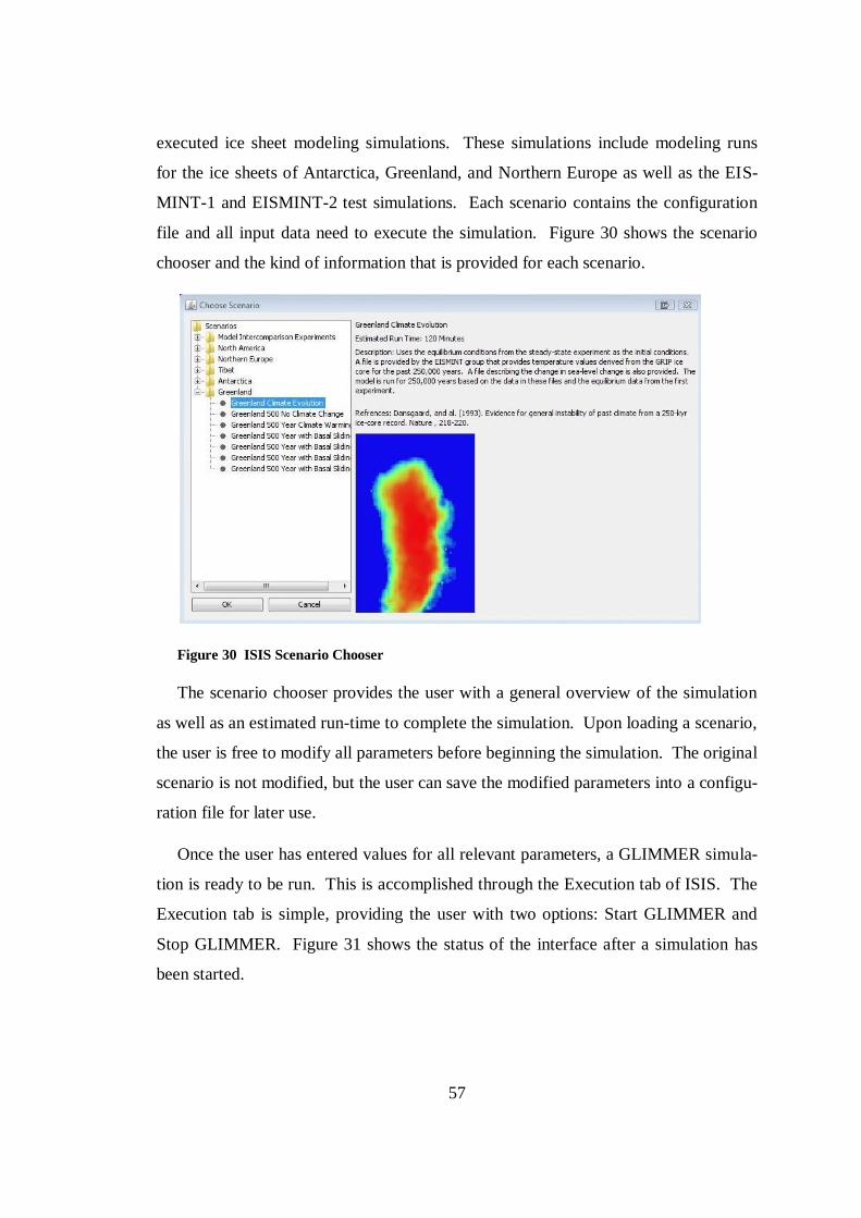
Figure 30 ISIS Scenario Chooser ......................................................................... 6.57
Figure 31 ISIS after beginning GLIMMER simulation ......................................... 6.58
Figure 32 ISIS Visualization Tab ......................................................................... 6.59
Figure 33 ISIS Analysis Tab ................................................................................ 6.60
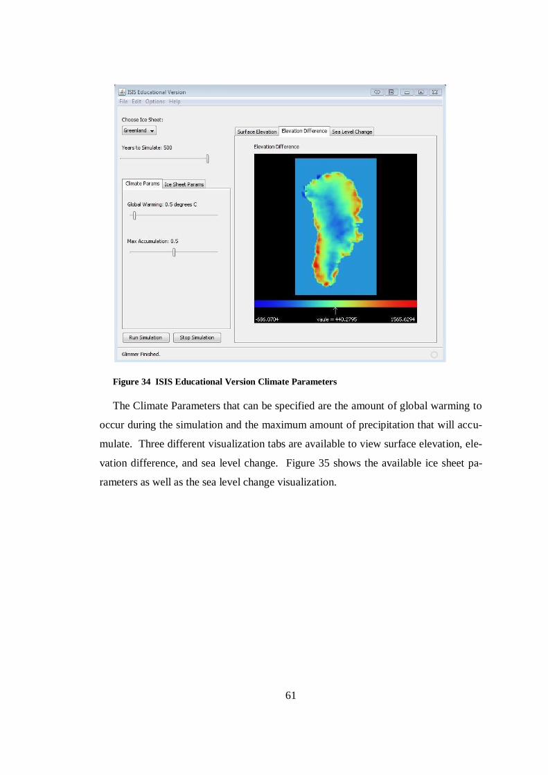
Figure 34 ISIS Educational Version Climate Parameters ...................................... 6.61
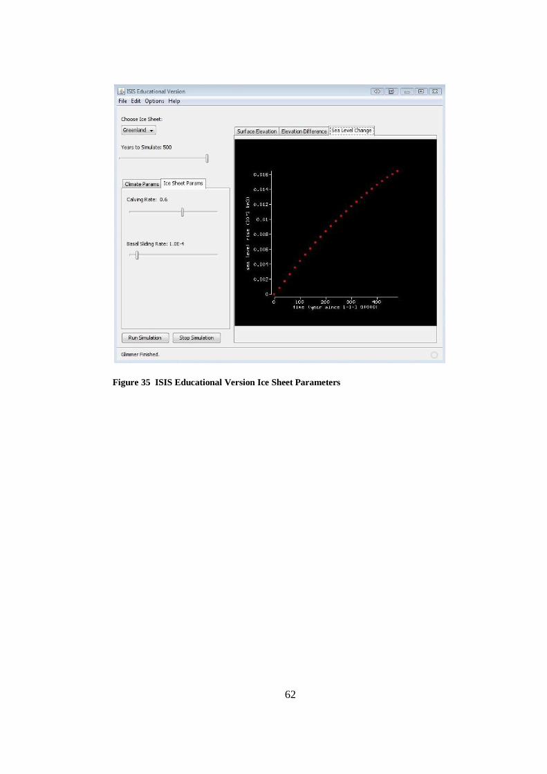
Figure 35 ISIS Educational Version Ice Sheet Parameters .................................... 6.62
Figure 36 Executing a PISM simulation from the Linux command line ................ 7.65
Page 9
1
CHAPTER 1 INTRODUCTION
1.1 Introduction
Development of software to be used in the scientific domain is a task occasionally
encountered by software engineers. These software projects present several interest-
ing challenges including lack of domain knowledge for the developers, need for rapid
development cycles, and adaptation to existing software products that may lack do-
cumentation and full functionality. These challenges make the development process
more difficult than for other types of software, but a software engineer can leverage
sound software design and implementation principles and practices to overcome chal-
lenges and produce products that help the scientist perform research and support the
spread of scientific concepts and techniques to a wide variety of users.
Scientific concepts are constantly evolving and our understanding of how our
world works is rapidly changing. This is especially true in the geological sciences,
particularly climate research. Climate research produces some of the most complex
and highly coupled computer simulation models in use today. As the scientific foun-
dation evolves and additional data becomes available, software applications must be
able to adapt and extend to new understandings and discoveries. The challenge of
creating software that is able to respond to these changes is a critically important goal
that must be supported throughout the software development process.
The project discussed in this thesis involves the development of a user interface to
interact with a pre-existing scientific software product. This project included many of
the challenges typically faced by software engineers when working with scientific ap-
plications. The need to quickly adapt the user interface to changes within the scientif-
ic software became a driving force behind the design and implementation of the re-
sulting software products.
While many development environments provide automated tools for specifying
both the look and functionality of user interfaces, these tools are meant for one-time
Page 10
2
usage early in the development process. These environments are not suitable for spe-
cifying a set of user interfaces that work seamlessly with a backend that implements
business or scientific processes. However, this is exactly what is needed across a
wide variety of applications, namely, the ability for the user to specify the interface
they want, including the number, type, and relationships between interface fields and
widgets.
This thesis describes how design patterns, specifically those proposed by Gamma
et. al, were used to create a tool that builds a functional user interface, not simply the
graphical portions or simple stubs of functions or methods (Gamma, 1995). The tool
creates the specification of a user interface to be used in conjunction with the scientif-
ic application. The resulting extensible markup language (XML)-based interface de-
scription language (IDL) allows for rapid adaptation of the user interface to the para-
meters of the scientific application. While the software products show the results of
pattern application and the creation of a dynamically produced user interface, it is the
process used and lessons learned that make this thesis of interest.
This thesis provides background to the problem; background necessary to under-
stand the application requirements and design goals. Next, the requirements and de-
sign of the products are presented and discussed. The implementation strategy and
challenges are described. Testing strategy is presented in order to complete the de-
velopment process. An overview of the resulting products is given, followed by the
lessons learned and future directions for these projects. The lessons learned includes
specifically what a reader would want to take from this thesis to leverage the expe-
rience of this process in their project.
1.2 Motivation
The work for this thesis was funded by NSF grant number – NSF-ANT0632161.
This grant was secured for the creation of a community ice sheet model similar to the
model that was used in the Intergovernmental Panel on Climate Change (IPCC) simu-
lations. This model was to be developed with end users in mind, which led to the cre-
Page 11
3
ation of a graphical user interface to work in conjunction with an ice sheet modeling
application, GLIMMER (GENIE Land Ice Model with Multiply Enabled Regions).
Two user interfaces were proposed: one for more advanced users and another for high
school and middle school students to be used in conjunction with an educational cur-
riculum developed through the grant.
The resulting software products are called ISIS (Interactive System for Ice Sheet
modeling) and ISIS Educational Version and are open source (Gnu Public License)
products available for download at http://www.cs.umt.edu/ISIS/.
Software design, coding, and testing of the main portion of the software product
were completed by the author and Geddy Tarbell between May 2007 and January
2008 under the guidance of Dr. Jesse Johnson and Dr. Joel Henry at The University of
Montana. Initial development of the visualization tools were completed by Alexander
Petkov between June and August 2007. This work was continued by James Fish-
baugh from August 2007 until January 2008. The grant is funded for two years and
work has been continued by several students and researchers at The University of
Montana and several other universities. This thesis outlines the development of the
ISIS software project from its conceptual phases through design and implementation
and the initial alpha release which was distributed starting in December 2007.
1.3 Background
The anticipated climate warming due to anthropogenic production of carbon dio-
xide has numerous environmental, economic, and societal consequences. Chief
among these consequences is the increase in sea level that is expected to result from
the melting of large ice masses in Greenland and Antarctica.
The primary means of assessing the amount of sea level rise is the ice-sheet model
(Hulbe & Payne, 2001). These models rely upon a “first principals” treatment of the
physics of ice flow, which results in a coupling of thermal and mechanical responses
of the ice. The computational complexity of such a formulation is intermediate, and
Page 12
4
most such models have been developed by small groups of researchers, working in
relative isolation.
The need to unite the community with a common ice sheet modeling platform has
become apparent as recent findings show that the uncertainty in sea level predictions
for 2100 is about 80 cm (Cubasch, et al., 2001). GLIMMER is an open source ice
sheet model that meets this challenge (Payne, 1999; Payne & Dongelmans, 1997;
GLIMMER, 2007). However, download statistics and journal publications show that
it has not yet seen widespread usage due in part to its lack of an intuitive user inter-
face.
In its present form, GLIMMER uses a textual configuration file to define model
behavior, set parameters, and structure model input/output (I/O). The creation of the
configuration file presents a significant problem to users due to its format and com-
plexity. A large number of parameters as well as insufficient documentation make it
difficult for a user new to GLIMMER or ice sheet modeling to perform even simple
simulations. ISIS and its related tools attempt to make this experience more user-
friendly, less complex, and more transparent to a larger group of people.
1.4 Goal
A single primary goal existed for this project at it outset. This goal was the crea-
tion of a user interface that could be used for executing GLIMMER ice sheet simula-
tions without the direct editing of the GLIMMER configuration file. The desire was
for an interface that could be used by a wider variety of user groups ranging from re-
searchers familiar with the use of GLIMMER to college students and finally to middle
and high school students with no previous experience in ice sheet modeling. This in-
terface would be designed in such a way that it could be extended and modified in or-
der to adapt to configuration changes in future versions of GLIMMER. This applica-
tion would be dubbed ISIS (Interactive System for Ice Sheet modeling). ISIS would
be available for use in all major operating systems including Microsoft Windows,
Mac OS X, and Linux.
Page 13
5
A secondary goal for was to integrate a visual browser into ISIS for the NetCDF
output files that GLIMMER produces from a successful simulation. This would be
developed concurrently, but separately from the development of ISIS and would be
merged into ISIS as components before distribution. Consolidation of simulation and
graphical tools into one package would enable a much larger audience to experiment
with ice sheet modeling and view the results.
The final goal was to provide an educational based version of ISIS. This interface
would provide a subset of the GLIMMER functionality at a level of abstraction more
easily understood by middle to high school students. This version would also contain
the visual browser developed for use with ISIS, with appropriate visualizations being
chosen to meet the needs of this age group. An education curriculum for teaching ice
sheet modeling would be developed using this application.
These initial goals were solidified as design and development commenced into the
set of requirements that are listed in Chapter 2.
1.5 Thesis Organization
The remainder of this thesis is organized as follows:
Chapter 2 discusses the requirements that drove the design and develop-
ment of ISIS and how they evolved from the initial goals.
Chapter 3 describes the design of the ISIS software project and its related
tools.
Chapter 4 describes the implementation process used for ISIS.
Chapter 5 addresses the testing techniques that were used for verifying the
correct functionality of ISIS.
Chapter 6 contains the results of the project and a brief overview of their
functionality.
Chapter 7 discusses future directions for the ISIS software project.
Chapter 8 provides a conclusion and lessons learned.
Page 14
6
Appendix A gives the procedure used to produce GLIMMER executables
for the Microsoft Windows operating system.
Page 15
7
CHAPTER 2 REQUIREMENTS
2.1 Requirements Analysis
The requirements analysis phase of a software project is one of the most crucial
stages. During this phase, it is important to identify the core features that must be im-
plemented within the software product and prioritize them in order of importance.
This can be accomplished by meeting with potential users of the software and taking
into consideration their needs as well as any system requirements. Specifying core
requirements allow them to be reviewed by users to ensure that their needs and not the
needs of the programmers will be met (McConnell, 2004).
For this software project, the primary users were the author and Dr. Jesse Johnson.
Dr. Johnson has extensive experience in the use of GLIMMER and a clear idea on the
functionality that would be needed in ISIS. The author had limited experience with
GLIMMER and could provide insight into the more typical user with a limited under-
standing of ice sheet modeling. Other users with no previous experience with
GLIMMER or ice sheet modeling were also considered as potential users, and their
needs were addressed during requirements analysis.
There are often pressures to move beyond requirements into the latter phases of the
software development process that produce more tangible output, but the software
analysis phase is critical to the success of a software product. If the core requirements
are not identified before implementation begins, significant rework or scrapping of the
entire project could occur. Requirements are inherently unstable, with customers and
users rarely able to convey exactly what features are needed in the end product
(McConnell, 2004) . This project experienced moderate changing of the requirements
as development commenced.
In addition to the goals outlined in Section 1.4, there were several other outside
forces driving the creation of requirements for ISIS. Several researchers from other
universities were also contributors on the grant funding the development of ISIS.
Page 16
8
These researchers needed working prototypes as early as possible in order to make
their contributions. A conference involving all contributors of the grant was sche-
duled after six weeks of work had been completed on the software and prototypes
demonstrating the functionality of ISIS were expected. This put additional pressure
into completing the requirements and design phases quickly and efficiently.
Since GLIMMER is open source and is in active development by other users out-
side of the ISIS development team, the desire was to develop ISIS with no modifica-
tion to the GLIMMER source code. ISIS would have no direct communication with
GLIMMER source code but instead simply launch GLIMMER as an external process.
It was decided early on that ISIS would work with GLIMMER by writing a configura-
tion file and then executing GLIMMER with this configuration file in the same way
that GLIMMER was currently run from the command line.
During requirements analysis, the development team learned that GLIMMER is a
constantly evolving program. As scientists using the platform explore new questions
in ice sheet modeling, the parameters, model behavior, and I/O specifications of
GLIMMER change. Hence, there are two major challenges. First, the dynamic na-
ture of GLIMMER itself, and second, the fact that GLIMMER is open source means
that changes are outside of the control of the user interface design team. The devel-
opment team decided that there should be an attempt to design ISIS in such a way that
it could be rapidly and easily changed in order to meet the ever changing state of
GLIMMER.
As stated in Section 1.4, the grant specified the creation of an educational version
of ISIS to be used by students in high school and middle school. The requirements
for this version were not initially formalized, but considerations were made that this
version would provide a subset of the functionality of the full version of ISIS.
Using the initial goals in Section 1.4 and the feedback from users, the requirements
were formalized into the list in the following section.
Page 17
9
2.2 Requirements Specification
The high-level requirements driving the design of this product were:
The ability to rapidly adapt the ISIS interface to the constantly changing GLIM-
MER source code.
The ability to create multiple interfaces to support educational outreach across
several academic levels.
These high-level requirements were expanded into the following list:
Cross-platform support for Microsoft Windows, Macintosh OS X, and Linux
Specify all relevant GLIMMER parameters
Error-checking to prevent incorrect data entry by the user
Save configurations for later use
Ability to execute GLIMMER simulations and monitor progress
Scenario chooser to allow the user to choose a premade simulation
Inclusion of relevant data files for simulations
NetCDF file viewer with appropriate options for viewing and analysis of GLIM-
MER output
Page 18
10
CHAPTER 3 DESIGN
3.1 Overview
The requirements listed in Section 2.2 were used as the basis for the design. As the
design process commenced, several important decisions were made that altered the
course of the project and how it was implemented. These changes are outlined in the
following paragraphs, followed by an overview of the design.
As the requirements for ISIS were specified, it was decided that a rules system
would be needed in order to verify the limitations that would be placed on the values
that could be entered for each parameter in ISIS. Each of these parameters would cor-
respond to an option that could be specified in the GLIMMER configuration file. Li-
mitations on these values could include minimum and maximum values, types that
could be specified (integer, decimal, string), and dependencies between various para-
meters. Since it was difficult to identify all rules from the GLIMMER documentation
and the author’s limited experience, it was decided that the rules should be specified
in an XML file so that they could be added as discovered.
Design began on the rules system, but it soon became apparent that not only were
the rules difficult to determine during design, but the parameters available for
GLIMMER were not clearly specified. The GLIMMER documentation provided with
the GLIMMER source code described the parameters that were available. These are
divided into sections within the configuration file. An example is the time section.
Within the time section, the user will specify parameters including tstart and tend,
which specify the starting and ending times of the model in years. There are a large
number of parameters in the documentation and not all contained clear descriptions of
their function and any limitations that pertained to them.
During the author’s previous experience with GLIMMER, parameters had been
used that could not be located inside the GLIMMER documentation. In addition, it
was known that there are often new parameters added to GLIMMER as development
Page 19
11
of its source code continues. These new parameters are usually added by researchers
using customized versions of GLIMMER in order to accomplish specific modeling
goals. The development team made the decision that specifying the entire interface
and not just the rules inside an XML file would help ISIS to adapt to these changing
conditions.
In order to specify information about the interface within an XML file, decisions
were made regarding what kinds of interface widgets would be available. It was ne-
cessary restrict the variety of graphical interface widgets to those suitable for scientif-
ic modeling software to meet development and delivery deadlines. While more user
friendly graphical user interface (GUI) widgets might have been better in certain situ-
ations, no loss of GLIMMER modeling functionality was sacrificed. Restricting GUI
widgets simplified design and implementation, allowing the team to meet exacting
delivery deadlines.
By analyzing the GLIMMER documentation, developers settled on four main types
of parameters accepted by GLIMMER. The first is a simple numeric input, either a
decimal or integer. A spinner widget was chosen for this type (see Section 3.2.1 for
widget images). The second type of parameter identified allows the user to select one
of several options. This was implemented as a drop-down box widget.
A third type of parameter was a list of data, delimited in some way. The delimita-
tion was not standard between all items of this type, so this was implemented as a
textbox allowing the user to enter the list of items with the appropriate delimitation.
The final type of parameter was specification of input or output file names. This was
implemented as a textbox for specifying the file using a file dialog box available for
choosing a file on the user’s machine. All of these UI widgets were implemented into
a set of classes that are discussed in Section 3.18. All UI widgets were dubbed “ele-
ments” during design and development.
The XML file format utilizes a hierarchy well-suited to the parameters available
for GLIMMER. The parameters are organized inside the GLIMMER configuration
file with a parent-child relationship. A parent usually contains several children such
Page 20
12
as the time example given above. Since the only interface between ISIS and GLIM-
MER would be through a written configuration file, it made sense to maintain the
same parent-child relationships within the XML. ISIS is then insulated from many of
the changes to GLIMMER through the XML file, which changes as GLIMMER
changes. An example of a simple GLIMMER configuration file is shown in Figure 1.
Page 21
13
Figure 1 Example of a simple GLIMMER configuration file
Once the widgets and their necessary settings were formalized, the intent was for
the developers to open the XML file and enter data for all GLIMMER parameters.
Page 22
14
This was quickly deemed to be infeasible. The number of parameters for GLIMMER
was too great and the file quickly became large and unwieldy. It was decided that
creation of a tool was needed to allow the user to enter data about parameters. The
tool would then write the XML file that could be read by ISIS at runtime to create the
user interface. Details pertaining to the ISIS XML Creator tool are provided in Sec-
tion 3.3. In effect, the author developed an interface specification tool to create the
XML file.
There were doubts as to the feasibility of this approach by some members of the
development team. Although many attempts have been made within the software en-
gineering field to interface description languages (IDL) for the creation of end-user
products, the toolset available has been largely incomplete. The use of an IDL-based
approach removes much of the control of the final presentation of the interface from
the developers. IDL-based products often lack the graphical polish of a standard user
interface. Many products developed using an IDL have failed to meet end user expec-
tations.
IDLs, in the general case, prove to be difficult to use during maintenance. The
IDL specification tool developed here is able to overcome this difficulty by restricting
user interface widgets and by using a restrictive XML file format. Given ISIS is not
meant to be a general purpose user interface tool but rather an interface tool for scien-
tific applications using configuration files, the typical IDL limitations do not present
problems.
Initially, the intent was to allow the end users to modify the XML file specifying
the interface to meet their own needs. This was deemed too risky (e.g., users would
specify relationships ISIS could not understand or implement) and the potential for
problems was too great (i.e., the error checking code for ISIS would be far larger than
the size of functional ISIS code). Once the decision was made to have the XML inter-
face file be a closed system only edited by developers, those doubting the approach
felt more confident that it would succeed. The development team decided that the
Page 23
15
risk in pursing and IDL-based approach was worth the effort as the potential payoff in
easy adaptation to changes in GLIMMER was a worthwhile goal.
The decision to develop a dynamically created interface led to engineering of two
separate products, both utilizing accepted design patterns in order to create an inter-
face specification tool called ISIS XML Creator and an interface presentation and
GLIMMER model launching tool called ISIS. The backend structure was later
adapted for use with the ISIS Educational Version. The design of the element struc-
ture backend common to all tools is presented in Section 3.2. The design of the ISIS
XML Creator is shown and discussed in Section 3.3. Section 3.4.1 describes the de-
sign of ISIS. Section 3.4.2 describes the ISIS Educational Version.
The design of both tools as well as the backend allow for a very extendable and
maintainable implementation. If a new UI widget is needed, an appropriate element
class can be created. Options are then added to the interface specification tool to al-
low the parameters of this new type of widget to be specified. These parameters are
then specified through the tool and added to the XML file. Once this XML file is read
into the interface presentation tool, the new widgets will be drawn into the UI.
3.2 Element Structure
The design of the backend element structure (referred to as Echo during develop-
ment) is shown in Figure 2. The design focuses on maintainability and extendibility.
As shown in the design, insulation from element types is provided through the Ele-
ment base class, which provides an interface to ElementRoot, ElementParent, Ele-
mentFile, ElementList, and ElementOptions. These classes correspond to the chosen
UI widgets. This portion of the design is further discussed in Section 3.2.1.
Page 24
16
Figure 2 Echo Design Diagram
Page 25
17
The goal of this design was to create a set of classes that were common to both the
interface specification and interface presentation tools. These classes needed to allow
creation of objects that represent the information needed for each control in the inter-
face as well as specification for how they are presented in the actual user interface.
Figure 2 shows the use of the Strategy, Composite, and Factory patterns. Strategy
is provided through the DependencyRule class which allows a family of algorithms to
be shared among Element objects, algorithms that can vary and be easily extended
with new algorithms. The Composite pattern has been applied to the inheritance hie-
rarchy with the base class Element. An Element can be a single element or the root of
an entire Element tree. The Factory pattern is readily apparent; ElementFactory im-
plements a factory. The lines to classes created by the factory have been omitted to
keep Figure 2 readable. All three of these patterns have standard implementation
schemes (Metsker & Wake, 2006).
The relationships between ElementManager, Element, and ElementRoot presented
a problem not amenable to a solution by accepted design patterns. Element objects
need a reference to ElementRoot objects and vice-versa, which introduces a circular
dependency. Circular dependencies are known to be hazardous to design maintaina-
bility and extendibility (Lakos, 1996). In this case, the circular dependency could not
be readily avoided. If a class was inserted between these two classes, the inserted
class would have circular dependencies with both Element and ElementManager,
which is clearly no better than a direct circular dependency.
It was decided to accept this dependency and limit the impact of changes through
the Element base class interface and ElementManager uniqueness (not inherited and
used by only two other classes). The development team considered the mediator pat-
tern to solve this problem, which provides a unified interface to a set of interfaces in a
subsystem. However, no need existed for multiple ConcreteMediator classes or mul-
tiple ConcreteColleague classes (Gamma, 1995). This would again only move the
circular dependency to another portion of the design rather than removing the depen-
Page 26
18
dency. The nature of the requirement drives the problem, not the implementation in
this case.
This design structure overall shows good insulation through the use of base classes
which serve as interfaces. Multiple dependencies have been captured by the Factory
pattern. The Strategy and Composite patterns solve known design problems. Circular
dependency has been accepted and negative effects localized. This design has been
used across three software products supporting consistency and reuse, while minimiz-
ing multiple changes in multiple files in multiple products, a known source of defects
and maintenance problems.
The following sections separate this design into smaller portions for more thorough
discussion.
3.2.1 Elements
Figure 3 shows the design structure of the element hierarchy. Since all UI parame-
ters share a similar set of attributes, an inheritance hierarchy worked especially well.
Classes outside of this hierarchy need to only be aware of the existence of the Element
class and none of the classes inherited from it. The only exception is the ElementFac-
tory class, which implements the Factory pattern.
Figure 3 Element Inheritance Hierarchy
The most important class in this design is the abstract base class Element. The
Element class specifies all attributes that are common to a UI widget. These include
Page 27
19
name, value, defaultValue, shortDescription, longDescription, ErrMsg, rules, parent,
children, label, and a control. This class is then inherited into six implemented classes
called ElementRoot, ElementParent, ElementRange, ElementList, ElementOptions,
and ElementFile. These classes are stored in a tree structure with each element class
storing references to its parent and its children.
The Element base class also contains several methods, which are overridden by the
inherited classes as needed. The most important of these methods are draw(), isVa-
lid(), and writeConfig(). Other methods include setters and getters as well as several
helper methods of lesser importance.
The hierarchy of the element structure always takes the following form: a single
instance of an ElementRoot class is the base of the tree. The ElementRoot class con-
tains any number of children that are of type ElementParent. All ElementParent
classes then contain at least one child of type ElementRange, ElementList, Elemen-
tOptions, or ElementFile. This inheritance is important as it is fundamental to the ex-
ecution of the three most important methods listed above.
The ElementRange class is used for GLIMMER parameters that have a numeric
input. Instances of this class have a type (Integer or Double) and a minimum and
maximum value in addition to the attributes of the Element base class. The type and
range restrictions are implemented as rules covered in the following section. The
widget for the ElementRange is a numeric spinner as demonstrated in Figure 4.
Figure 4 ElementRange numeric spinner
The ElementOptions class is used for GLIMMER parameters that have a set list of
possible inputs to choose from. These are often represented as numbers in the
GLIMMER configuration file, with each number having a textual meaning. An ex-
ample would be the temperature parameter in which 0 is isothermal and 1 is full. All
parameters in an ElementOptions widget are represented with a full description in
Page 28
20
ISIS as shown in Figure 5. Behind the scenes, these descriptions map to the numeric
inputs that are expected by GLIMMER.
Figure 5 ElementOptions drop-down box
A class called ElementOptionsExecutable was inherited from ElementOptions for
the specialized purpose of selecting the type of model that would be simulated. These
model types correspond to different GLIMMER executables that must executed to
start the simulation. This class needed to have a different implementation of the wri-
teConfig() method. A method was also added to return the selected executable for
use with launching GLIMMER. The appearance and other functionality of this class
remains the same as ElementOptions.
Figure 6 ElementOptionsExecutable drop-down box
The ElementList class serves several purposes, but is used primarily for GLIM-
MER parameters that consist of a textual string. An example is the CF default sec-
tion, which has several parameters to specify the title, institution, and comments for a
modeling run. Another example is the sigma_levels parameter, which is represented
by a list of ascending numbers between zero and one, separated by spaces. As shown
in Figure 7, the control for ElementList is represented by a textbox, allowing input of
textual or string-based data.
Figure 7 ElementList textbox
Page 29
21
The fourth type of widget that was needed for ISIS was a file widget. Three types
of file parameters were identified for GLIMMER. The first is an input file where only
a single input file can be specified. The second is an input file in which multiple data
files can be input for a single parameter. The final type that was identified was a pa-
rameter where multiple output files could be specified. Another level of inheritance
was added to the ElementFile class, and the three file types were implemented as
ElementFileSingleIn, ElementFileMultipleIn, and ElementFileMultipleOut.
The ElementFileSingleIn class is used for parameters such as the temp_file para-
meter contained within the EIS Temperature section of the GLIMMER configuration
file. For this parameter, the user must input a single file containing temperature data.
The control for ElementFileSingleIn was implemented as a text box for specifying the
file path, with a button providing a file dialog for choosing the file path graphically.
Figure 8 and Figure 9 demonstrate the ElementFileSingleIn widget and the file dialog
provided upon clicking the button.
Figure 8 ElementFileSingleIn textbox and file dialog button
Page 30
22
Figure 9 File Dialog
The ElementFileMultipleIn class is used for GLIMMER parameters in which mul-
tiple input files can be specified. An example is the CF input section in which any
number of NetCDF files can be specified as data input into the model. ElementFile-
MultipleIn also uses a textbox and a button as its controls, but a second button is add-
ed for inserting additional file inputs. ISIS currently limits the number of file inputs
to twelve, but the design is flexible to allow this to be changed to any number of input
files.
When specifying these kinds of input files, the user also needs to specify the time
step within the NetCDF file to begin reading data from. This functionality is provided
through the containment of an ElementRange object within the ElementFileMultipleIn
class. The lower panel within the ElementParent panel that is usually used to provide
descriptions of each control contains the instance of ElementRange control for speci-
fying the time step. Figure 10 shows an example of two file inputs and the corres-
ponding control for specifying the time step for input file 2. Note that the lower panel
Page 31
23
containing the ElementRange control changes as the user navigates between file in-
puts.
Figure 10 ElementFileMultipleIn controls with ElementRange for specifying time step
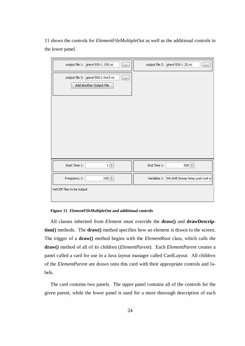
ElementFileMultipleOut is used for GLIMMER parameters in which multiple out-
put files can be specified by the user. An example is the CF output parameter which
allows the user to specify any number of NetCDF output files to write output data to.
The ElementFileMultipleOut class also needs to have additional parameters specified
about the output data. This is accomplished through the containment of three Elemen-
tRange and one ElementList objects. These represent the start time, end time, and
frequency of file output as well as the output variables to be written to the file. Like
the ElementFileMultipleIn class, these values are specified in the lower panel. Figure
Page 32
24
11 shows the controls for ElementFileMultipleOut as well as the additional controls in
the lower panel.
Figure 11 ElementFileMultipleOut and additional controls
All classes inherited from Element must override the draw() and drawDescrip-
tion() methods. The draw() method specifies how an element is drawn to the screen.
The trigger of a draw() method begins with the ElementRoot class, which calls the
draw() method of all of its children (ElementParent). Each ElementParent creates a
panel called a card for use in a Java layout manager called CardLayout. All children
of the ElementParent are drawn onto this card with their appropriate controls and la-
bels.
The card contains two panels. The upper panel contains all of the controls for the
given parent, while the lower panel is used for a more thorough description of each
Page 33
25
parameter as specified in their drawDescription() method. This lower panel is also
used for additional parameters that must be specified for the ElementFileMultipleIn
and ElementFileMultipleOut elements. Figure 12 shows the complete panel for the
ElementParent isostasy.
Figure 12 ElementParent complete panel
The ElementRoot contains a showCard() method that is called to display the ap-
propriate parent panel depending on where the user has navigated in the interface, par-
ticularly within the tree widget formed by the DynamicTree class that is discussed in
Section 3.2.3.
Every element contains a shortDescription and a longDescription. The shortDe-
scription is used to create a tooltip for every element, while the longDescription is
used for the description that is displayed in the lower panel of the parent card. Figure
Page 34
26
12 shows the use of the longDescription for relaxed_tau as the description displayed
in the lower panel. Figure 13 shows the short description for the update parameter
displayed as a tooltip when the user places the mouse over the label or numeric spin-
ner.
Figure 13 Tooltip using shortDescription
Early in the design phase, the decision was made that the development team would
be making no changes to the GLIMMER source code. The only way to start GLIM-
MER simulations would be to create a GLIMMER configuration file and then call on
GLIMMER to execute the simulation using this file. ISIS must be able to correctly
create the configuration file expected by GLIMMER. In addition to using the confi-
guration file for launching GLIMMER simulations, this format was used for saving
current ISIS configurations for later use. ISIS uses the existing GLIMMER configu-
ration file for saving and then reading configuration data specified through ISIS. The
writing of configuration files was accomplished using the writeConfig() method.
The writeConfig() method is executed in a manner similar to the draw() method.
The writeConfig() method is called within the ElementRoot class, which in turn calls
the writeConfig() of all of its children (ElementParent). GLIMMER configuration
files are divided into sections, with each section represented by an ElementParent in-
stance. Each ElementParent calls the writeConfig() of each of its children which re-
turns a string containing its parameter-value pair. The ElementParent places its name
inside of square brackets ([]) and combines all the strings of its children to form its
section. This is returned to the ElementRoot object and combined with all Element-
Parent sections to form the configuration file. Figure 14 shows the string that would
be returned by the writeConfig() method of the options parent.
Page 35
27
Figure 14 Returned value of the writeConfig() method for ElementParent options
GLIMMER configuration files do not often contain values specified for every
possible parameter. If a parameter is not specified, GLIMMER assumes default val-
ues. Significant effort was made to ensure that ISIS could read existing GLIMMER
configuration files and then rewrite them with the same parameters that were read in,
rather than rewriting all parameters available. This was accomplished by setting a
Boolean loadedFromConfig to true when a parameter is read in from a configuration
file. When the writeConfig() method is called on an element, a the parameter value
pair is only returned if the parameter was loaded from a configuration file or if the
value has been changed from the default value. This logic keeps configuration files
clean and simple.
The third method that is most important to the functionality of this structure is the
isValid() method used in conjunction with the rules system, covered in Section 3.2.2.
The element structure provides a great deal of flexibility. New types of classes can
be added by inheriting from the Element class and overriding the appropriate me-
thods. This allows additional interface widgets to be created if the need ever arises.
The design allows these additions to be made with a minimal amount of code rework.
3.2.2 Rules
When designing the element structure, it was clear a rules system was needed to
maintain the restrictions on individual elements as well as the dependencies between
the elements. These rules would be contained within the element structure in the
Page 36
28
XML file so they could be added and modified without changing the source code.
The rules system provides important error detection and correction information to the
user, information not available when specifying values by hand as they are entered
into a GLIMMER configuration file.
Analyzing the GLIMMER documentation, several types of rules were identified.
The first type of rule was a rule to specify the type for numerical input, specifically an
integer or a decimal number. The second type of rule identified was a rule specifying
boundary conditions for an element. The final type was a dependency between two
elements, which was later expanded into three specific types.
All rule classes inherit from the base class Rule. Each element in the element struc-
ture can contain any number of rules. The class Element only knows of the existence
of the base class Rule, allowing additional rule types to be created without affecting
the implementation of the element structure. Each instance of an element will contain
references to one or more rules that pertain to it. Figure 15 shows the inheritance hie-
rarchy of the rules system and its connection to the element structure through the
Element base class.
Figure 15 Rules Inheritance Hierarchy
The rules system works in conjunction with the isValid() method of the element
structure. The isValid() method is executed in a similar manner to the draw() and
writeConfig() methods in which the call to the method begins in the ElementRoot
class and then is propagated through the remainder of the element structure. A
change of focus within the user interface triggers the call to the isValid() methods.
Page 37
29
When the calls reach the lowest level of the element structure, the individual elements
loop through all of their rules, calling the isValid() method of each rule that they are
storing.
After validating all of the rules, an element makes a call to the setLabelColor()
method. This method will change the color of the element’s label to red if there was
an invalid rule or back to the standard black if the rule has been fixed. An example is
when the user enters an invalid file path for an input file of type ElementFileSingleIn.
The label is changed to red and the tooltip is changed to represent what the current
error is.
Figure 16 Use of setLabelColor() to show invalid file path
The TypeRule class is used to specify the type of an element. This is primarily
used for the ElementRange class to check if the value of the element is the correct
type (integer, decimal, or string). The TypeRule is set to either int, double, or string.
When the isValid() method of this rule is called, the current value of the control is
checked to see if its value is of the proper type. During implementation, this rule was
largely rendered unnecessary. The use of the Java numeric spinner allowed the type
to be set within the spinner, which prevents the user from entering an invalid type.
The BoundRule class is used for placing boundary rules on elements. BoundRule
is an abstract class and is inherited into two classes, BoundRuleRange and BoundRu-
leString. BoundRuleRange is used for specifying minimum and maximum values for
elements. The isValid() method checks if the current value of the element containing
the rule is within the boundaries specified within the rule. BoundRuleString is used to
check if the current value of an element is equivalent to the string specified within the
rule. In addition to being used as boundary rules for elements, these rules are also
used in conjunction with the dependency rules, specifying the range in which the de-
pendencies must be enforced.
Page 38
30
The dependency rules are used for specifying dependencies between elements.
These dependencies can exist between elements of any type except for ElementRoot.
The dependency rules all inherit from the class DependencyRule, which inherits from
Rule. The three types of specific dependency rules are DependencyRuleBounds, De-
pendencyRuleRequired, and DependencyRuleVisibility.
Dependency rules are stored such that an element stores rules about all elements
that are dependent on it. This allows the element to validate its rules against its cur-
rent value and then trigger the appropriate actions on those elements that are depen-
dent. This hierarchy was chosen since most of the rules are dependent on the value of
the element that is depended on. If an element were to store rules about the elements
it was dependent on, it would not have access to the values of those elements. Im-
plementing access to values of other elements introduces significant coupling and
makes encapsulation and information hiding impossible.
All of the dependency rules store a reference to the dependent element and an array
of containing BoundRule objects. These boundary rules specify in what range of val-
ues the dependency holds. These boundaries can be numeric or string based by using
the BoundRuleRange and BoundRuleString classes. Multiple boundary rules can be
used to accomplish more complicated relationships. For example, if a dependency on
an ElementRange type is valid given a value of 1, 3-6, and 9, three BoundRuleRange
instances must be specified within the dependency rule.
DependencyRuleBounds is used to specify relationships in which given a certain
value for an element, the value of another element must fall within a certain range.
This is type of rule would commonly be used to create a relationship between and
ElementOptions and an ElementRange. If the user has selected a given value from the
dropdown box for the ElementOptions control, the ElementRange would be restricted
to a range of values.
DependencyRuleRequired is used when the specification of a certain value for an
element specifies that a value must be provided for another element. An example
would be that if the user chooses to hot start the GLIMMER simulation (continue a
Page 39
31
previous simulation based on conditions stored within a NetCDF data file) using the
hotstart parameter, they must provide a NetCDF hotfile as input. The user will not be
able to save the configuration file or run simulations until a valid hotfile is specified.
DependencyRuleVisibility specifies that given a certain value for an element,
another element is visible. If an ElementParent is the dependent element and is set to
not be visible, the node is not displayed in the tree widget as discussed in the follow-
ing section. Since the node is not displayed in the tree widget, the card containing all
of the ElementParent’s children will not be viewable. This kind of relationship is
commonly used between the ElementOptionsExecutable Model Selection and a num-
ber of parents. When the user chooses between the different types of models, differ-
ent parameters will be available to the user through use of the DependencyRuleVisibil-
ity. The other parameters will be hidden because they are not included in the selected
type of modeling run.
DependencyRuleVisibility can also be used between two children elements. In this
case, if an element is set to not be visible, the element will appear on the screen but
will be grayed out and unusable. This allows the user to see that that parameter is
available, but is not relevant given the currently specified parameters. This also pre-
vents awkward screen redraws that would occur if the parameter was hidden as op-
posed to being grayed out.
The rules system is important for providing error checking to the end user. The
user will not be able to save configuration files or execute GLIMMER simulations
until all violated rules have been corrected. Many simulations can take several hours
or even days, so discovering errors before executing the simulation is very important.
However, the system prevents the user from discovering incorrect but legal parameter
values input to ISIS and written to the configuration file once the GLIMMER simula-
tion has been started.
Page 40
32
3.2.3 Logic
The DynamicTree class serves as the logic system of the element structure. All
connections between the various user interfaces and the element structure are made
through this class. In the early stages of the design, the DynamicTree was intended to
serve as a tree widget for displaying the element structure within ISIS. This role was
later expanded into serving as a full logic class, with methods to provide all of the
needed functionality to the other systems. Logical methods include writing the ele-
ment structure to an XML file and saving the current values to a configuration file.
The DynamicTree is displayed to the user as a tree widget. Both the ISIS XML
Creator and ISIS tools use this tree widget as the basis for specifying and presenting
the UI controls. The tree has a slightly different behavior depending on the tool that
is using it. If a user interface is created that does not need a tree control, the logic me-
thods can be used without the presentation of the tree.
The separation of the logic into this DynamicTree class simplifies the adaptation of
the element structures to the various tools that rely on its use. By limiting connectivi-
ty between these tools and the element structure, the tools are insulated from any
changes that occur to the element structure. If methods within the structure are
changed, adaptations only need to be made to the DynamicTree class instead of the
individual tools.
3.2.4 Other Classes
Several other classes that are critical to the design, but fall outside of the imme-
diate element hierarchy are the Constants, ElementManager, ElementFactory, Glim-
merLaunch, and LogFile classes. Figure 17 shows the relationship between these
classes and the other portions of the design.
Page 41
33
Figure 17 Helper classes and their integration into the design.
A factory pattern was implemented through the use of a class called ElementFacto-
ry. This class is responsible for creation of all element types and their associated
rules. By encapsulating the creation of objects to one class, the duplication of code
within individual element classes can be prevented. The factory pattern also eases the
addition of new types of elements to the element structure. The ElementFactory me-
thods are necessary for use with the interface specification tool discussed in Section
3.3.
The ElementManager class is responsible for all other actions required on the ele-
ments and element structure such as retrieving a specific element from the structure.
The ElementManager class contains methods for writing parameter values to a confi-
guration file, loading a configuration file values, and serializing the element structure
to XML. These methods are initialized through the DynamicTree class by the various
tools that utilize the tree for logic methods.
A reference to the root element of the structure is stored within the DynamicTree,
ElementFactory, and ElementManager since all three classes need access to the ele-
ment structure. The DynamicTree class stores references to the ElementFactory and
ElementManager classes since access to their methods by other subsystems must oc-
cur through the tree class. Finally, the ElementFactory stores a reference to the Ele-
mentManager in order to use its methods such as retrieving a specific element from
Page 42
34
the structure. The circular references that occur in this section of the source code
were not readily avoidable and are isolated to a small portion of the source code.
The Constants class contains values specifying the sizes for all portions of the UI
components. Element classes use these values within their draw() methods to set the
sizes for panels and controls. Isolation of these size values to the Constants class al-
lows sizing to be modified in one location without accessing all of the source code for
each element type. The Constants class also contains file path specification for where
the interface presentation tools will write output files and save configuration files.
The GlimmerLaunch class contains methods to start a GLIMMER simulation given
a configuration file as input. These methods are accessed by the model launching
tools through the DynamicTree class. The GlimmerLaunch class determines which
operating system the software is currently running on in order to determine the me-
thod that should be used to start the simulation. GlimmerLaunch also contains a me-
thod to stop the currently running simulation.
The LogFile class works in conjunction with the GlimmerLaunch class to read the
GLIMMER log file and display it to the user in the model launching tools. These
tools pass a reference to a text area through the DynamicTree to the LogFile class for
writing the contents of the log file to as the simulation executes.
The GlimmerLaunch and LogFile classes provide flexibility to the design by allow-
ing the swapping of these classes to allow different modeling applications to be
launched. Section 7.2 provides an overview of adapting these classes to allow ISIS to
launch ice sheet simulations using the PISM application as opposed to GLIMMER.
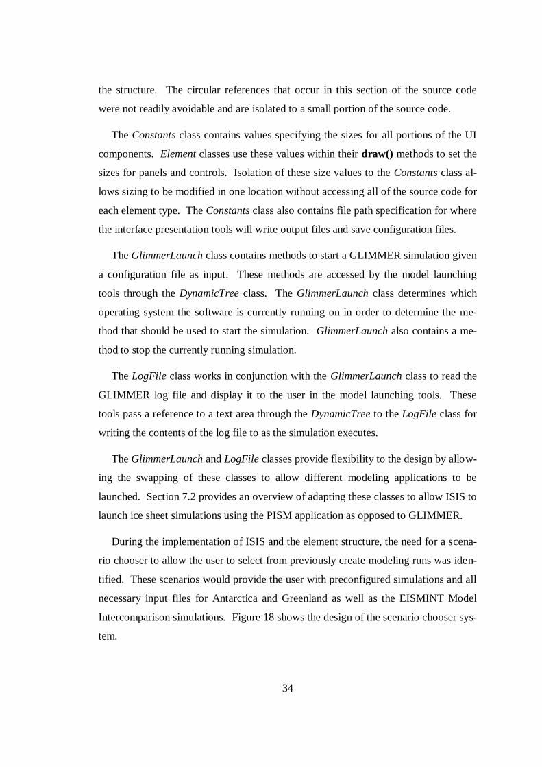
During the implementation of ISIS and the element structure, the need for a scena-
rio chooser to allow the user to select from previously create modeling runs was iden-
tified. These scenarios would provide the user with preconfigured simulations and all
necessary input files for Antarctica and Greenland as well as the EISMINT Model
Intercomparison simulations. Figure 18 shows the design of the scenario chooser sys-
tem.
Page 43
35
Figure 18 Scenario Chooser Design Diagram
The classes of the scenario chooser subsystem are accessed through the DynamicT-
ree class. The ScenarioChooser class consists of a dialog box allowing the user to
select from the available scenarios. These are stored within objects of type Scenario-
Group. Each group can contain any number of objects of type Scenario. These
groups and scenarios are displayed within a tree widget contained within the Scenari-
oChooser dialog box. After choosing a simulation, a configuration file containing the
necessary parameter values is loaded by ISIS.
The list of available scenarios is stored within an XML file that is loaded at run-
time. This allows additional scenarios to be added or existing ones to be edited with-
out modification of the source code. This ability combined with the interface XML
file provides a very flexible design.
3.3 Interface Specification Tool
The interface specification tool, or ISIS XML Creator, was designed to be simple,
yet adaptable to changing requirements. The design for this tool used a more agile
and less structured method since it was the first piece of software implemented and
had to be done in order to begin development of ISIS. ISIS XML Creator would be
used only when GLIMMER configuration files changed and therefore would not be
used often or for any length of time. ISIS, however, would be used frequently for
long periods of time making it important to rapidly build ISIS XML Creator and dedi-
cate more time, effort, and design knowledge to ISIS. The components making up the
design of the interface specification tool are shown in Figure 19.
Page 44
36
Figure 19 ISIS XML Creator design diagram
The Logic class initializes the interface, making calls to the MainFrame class to
display the interface to the user. The connection to the element structure occurs
through interaction with the DynamicTree class. The DynamicTree class was initially
designed for use with the ISIS XML Creator. This design was later adapted for use
with ISIS and the ISIS Educational Version.
The DynamicTree class displays all nodes that have been added to the tree. Each
node represents one element contained within the element structure. The user can na-
vigate this tree to add, edit, or remove nodes. Upon editing a node, the user is pro-
vided a panel within the interface to specify all attributes for the type of element they
are creating or editing. The DependencySpecification class provides the user with a
dialog box to allow dependencies between elements to be specified.
The ISIS XML Creator collects all of the specified parameters and dependencies
for a new or edited element into a standard data type. This structure is passed through
the DynamicTree class to the ElementFactory class. The ElementFactory class parses
this structure and creates a new element of the proper type with the proper values.
The ElementFactory also creates the dependencies between elements if any have been
specified.
If new element widgets are added to the element structure design, new panels can
be added to the ISIS XML Creator in order to allow specification of parameters for
these types. Code must also be added to the ElementFactory in order to allow it to
create elements of this new type. This design allows adding of new element types to
this tool to occur with a minimum of changes to the code.
Page 45
37
Ones the user has finished creating or editing an element structure using the tool,
the structure needs to be written to XML for use with the ISIS or ISIS Educational
Version interfaces. This is accomplished through a technique called serialization, in
which an object’s current state is written to some sort of storage medium in a standard
format. Instead of writing a custom serialization class, the XStream library was used.
XStream is open source software that is made available for free use under a BSD li-
cense (XStream - License). This Java library allows the serialization of objects to
XML, which can then be written to a file or other storage. This XML file can then be
deserialized back into the object structure that preexisted.
An example of an XML file produced through serialization is shown in Figure 20.
Each field in the XML file maps to some attribute in one of the element class objects
that was serialized. The simple example given above shows the XML format with the
root element, one parent, and one child specified. The child is of type ElementRange
and the fields contained within the ElementRange class can be seen within the XML.
Some attributes were not serialized to the XML and are reinstantiated upon unseriali-
zation.
Page 46
38
Figure 20 Example of an XML file produced by the ISIS XML Creator
XML files created by the ISIS XML Creator can later be deserialized and edited
using this tool. This allows a base interface file to be created and then edited as
needed. This may occur in the form of adding new elements or simply editing the
values of current elements. This system provides the desired ability to adapt the inter-
face to meet the changing state of GLIMMER.
Page 47
39
3.4 Interface Presentation Tools
3.4.1 ISIS
ISIS serves as the primary interface presentation tool, which allows the creation of
GLIMMER configuration files and the launching of GLIMMER simulations. The
high-level design of ISIS is shown in Figure 21.
Figure 21 ISIS Design Diagram
The ISISApp class initializes the application, calling the ISISView class to display
the user interface to the screen. ISISView communicates with the element structure
through the DynamicTree class using the same methods as the ISIS XML Creator.
ISISView also communicates to the visualization subsystem through the ScientificDis-
playPanel and SeaLevelDisplayPanel classes. The ISISAboutBox class simply serves
as a dialog box providing information about ISIS to the user.
Upon initialization, the ISISView class makes a call to the DynamicTree class to
deserialize the XML file that is specified within the code. Using the XStream library,
the XML file is inflated to the set of objects represented within the XML file. The
state of these objects is identical to their state prior to serialization through the ISIS
XML Creator. ISIS never modifies the XML file, and the objects are deserialized into
the same state upon execution of ISIS each time it is launched.
The DynamicTree class is displayed to the user in the same manner as the ISIS
XML Creator but functions differently. As the user navigates the tree structure, ap-
propriate methods are called within the element structure to display the correct panels
to the user interface. The Java focus system was used to allow focus to be transferred
Page 48
40
to the correct element widget as the user navigates the tree. This also works in re-
verse, with user navigation within the element widgets highlighting the correct tree
node within the dynamic tree.
ISIS makes use of a visualization subsystem that was designed independently from
Echo, ISIS XML Creator, and ISIS. ISIS was designed to be componentized. Within
the design of the UI portion of ISIS, room was left for the visualization and analysis
portions. This was accomplished through use of Java panels. The developers of the
visualization and analysis tools were instructed to design their systems to display to
the screen using a panel of a specified size. Upon completion of their tools, only a
few lines of code need be added to the design to allow proper communication to these
panels. This design allows these portions to be swapped out for newer panels if better
tools are developed with minimal changes to the code of ISIS.
3.4.2 ISIS Educational Version
The ISIS Educational Version was designed following the implementation of ISIS
and uses a very similar design. The design of this tool is shown in Figure 22.
Figure 22 ISIS Educational Version Design
The ISIS Educational Version application functions in the same manner as ISIS,
described in Section 3.4.1. The ISIS Education Version also uses a visualization sub-
system. The SeaLevelDisplayPanel is identical to that used in ISIS. This application
also uses two additional visualization panels called EduSurfaceElevation and EduEle-
vationDifferancePanel. Screen space for these panels was reserved within the UI
Page 49
41
frame. Communication with the ISISEduView class takes place through a simple in-
terface, allowing the panels to be modified or replaced without change to the imple-
mentation of the ISIS Educational Version.
The main difference between the ISIS Educational Version and ISIS is the use of
the DynamicTree class. The ISIS Educational Version does not use the DynamicTree
class as a display widget, instead using only its methods to communicate with the
element structure. This prevents code rework and maintains compatibility with the
standard version of ISIS.
Since this version only uses a small number of parameters, the dynamically created
interface is not needed. The XML structure is still deserialized upon runtime, but on-
ly the values of certain elements will be modified. The UI widgets can either map
directly to an element, or they might modify the value of several elements in order to
achieve the desired effect. For example, there is no GLIMMER parameter
representing the option contained in the ISIS Educational Version for global warming.
Global warming is achieved by creating a temperature file and supplying it to
GLIMMER as a parameter. The user is unaware of these additional behind-the-
scenes steps. The GLIMMER parameters that are not manipulated by the ISIS Educa-
tional Version remain at their default values.
Page 50
42
CHAPTER 4 IMPLEMENTATION
4.1 Implementation Strategy
Implementation of these tools presented an interesting dilemma. If the tools were
created in parallel, then the risk of rework would be high in that the interface specifi-
cation tool might require changes that would invalidate work on the interface presen-
tation tool. However, a sequential implementation (specification tool implemented
completely first, then the presentation tool implemented) would not meet the delivery
deadline.
While it is theoretically possible to specify a design completely in advance and
then implement without changes, in practice this rarely occurs. The solution was a
“thin” implementation of the specification tool in order to encounter as many prob-
lems and make as many changes as possible. In this case, “thin” meant a streamlined
top-down implementation of a thread of functionality that created one GUI widget.
This allowed a learn-as-you-go experience and captured most of the changes that typ-
ically occur in during the implementation of a design.
This implementation method followed the pattern of an iterative development
process, with the addition of direct contact with a GLIMMER user. The iterative
process usually involves significant overlap between the specification, design, and
development (Sommerville, 2004). Certain portions of the design were filled in as
implementation continued and additional details were uncovered. The insertion of
user contact into this process proved to be helpful, preventing the developers from
making assumptions as to how GLIMMER functioned and the nature of the configu-
ration files. Overall, the implementation process proved to be successful.
Since one of the goals of the project was cross-platform support for Microsoft
Windows, Mac OS X, and Linux, the Java programming language was chosen for im-
plementation. Each of these operating systems can install a Java virtual machine that
enables them to run applications that have been coded using the Java programming
Page 51
43
language. Java version 1.6 was used for all development. Cross-platform support
was made more difficult due to the lack of GLIMMER executables for all operating
systems. Appendix A provides an overview of the process used to create GLIMMER
executables for the Microsoft Windows operating system.
4.2 Element Structure Implementation
The first thread of the thin implementation included coding of the backend element
structure. This included all of the Element classes and their appropriate methods. De-
tails of how these classes would be displayed were left incomplete. The Rule, Boun-
dRule, and TypeRule classes were also implemented at this point since the Elemen-
tRange class was dependent on these. DependencyRule classes were implemented
later once the actual dependencies that were needed for GLIMMER were better un-
derstood.
Implementation of the ElementRange class was undertaken first. This was leve-
raged into creation of the ElementOptions class and then the ElementList class. Final-
ly, the ElementFile and its three inherited classes were implemented. Effort was
made to prevent code duplication wherever possible and to move any code that was
general between all element types to the Element base class.
4.3 Interface Specification Implementation
The interface specification tool ISIS XML Creator proved to be more time con-
suming to develop, although not necessarily more difficult, than the interface presen-
tation tool ISIS. Implementing this tool required creation of the ElementFactory class
and the ElementManager classes. The user interface for this tool was created to col-
lect the appropriate data and pass it through the DynamicTree class to the Element-
Factory for object creation. A significant amount of work was done to ensure that
future UI widgets could be added to this interface with minimal effort.
As mentioned previously, the DynamicTree class was implemented as a tree wid-
get. Both the specification and presentation tool were intended to use a tree as a main
Page 52
44
portion of the interfaces. The DynamicTree class was written to be general enough to
serve as a UI widget as well as the logic of the system. During the implementation of
the ISIS XML Creator, the DynamicTree widget was created, with considerations be-
ing made to allow the appropriate functionality to be added during implementation of
the presentation tool.
4.4 Interface Presentation Implementation
Creation of the interface presentation tool proved to be fairly straightforward. The
biggest step at this point was implementing the draw() method of each Element class.
This draw() method specifies what kind of control each class will use to display itself
to the screen. Again, the ElementRange draw() method was implemented first, and
this code was leveraged to create the draw() methods for the other classes.
A frame was created using four tabs: Configuration, Execution, Visualization, and
Analysis. Initially, only the Configuration tab was implemented. This tab contains
the DynamicTree widget and is where all parameters for GLIMMER are viewed and
edited. An XML file was created using the ISIS XML Creator containing information
about a small number of parameters in order to test the functionality. Appropriate
methods were added to the DynamicTree class to allow proper communication be-
tween ISIS and the element structure.
Once this step was completed and ISIS was able to draw elements, additional me-
thods were added to enhance the functionality. The remainder of the draw() methods
were completed. Methods to allow focus to transfer from the tree to element widgets
and vice-versa were implemented. The ElementManager had methods added to allow
GLIMMER configuration files to be saved onto the local machine using the output
path specified. Another method was implemented to allow the saved or preexisting
configuration files to be read into ISIS.
Once these changes were made and ISIS correctly allowed users to set GLIMMER
parameters and save them to a file, implementation of the Execution tab began. This
tab allows users to start and stop GLIMMER simulations as well as view the log file
Page 53
45
that is output by GLIMMER. This implementation was completed within the Glim-
merLaunch and LogFile classes. Special considerations were made within this class
to allow GLIMMER to be correctly executed from Windows, Linux, and Mac envi-
ronments.
The implementation of the Visualization and Analysis tabs were completed next.
This was fairly simple and only involved making appropriate calls to initiate the pa-
nels that had been implemented by the other developers. A minimal amount of cod-
ing had to be completed so that the correct NetCDF files were being passed to the vi-
sualization subsystem.
At this point, a complete XML file containing all known GLIMMER parameters
was created. The GLIMMER documentation and the knowledge of GLIMMER users
were leveraged to create the correct parameters as well as specify the proper limita-
tions and default values. This process was somewhat difficult due to incomplete do-
cumentation, but the nature of the ISIS XML Creator tool allowed this XML file to be
edited and enhanced as new information was discovered.
Implementation of the ISIS Educational Version was begun at this point in the de-
velopment cycle. Large portions of the code written for ISIS were reused, which
made implementation a much easier process. As stated previously, the ISIS Educa-
tion Version does not use the dynamic XML interface. A static set of widgets were
created for this version which is what was being avoided in the implementation of
ISIS.
The small number of widgets and the functional stability of these widgets allow
this compromise to be made. Even though the ISIS Education Version does not use
the element structure to display widgets to the screen, the structure still functions be-
hind the scenes. As the XML interface file is modified for ISIS, the same file will be
used for the ISIS Educational Version so that the element structure corresponds to the
current version of GLIMMER configuration parameters.
Page 54
46
Once ISIS was correctly functioning at a basic level, additional code was imple-
mented to provide better error-checking and error recovery. This came primarily in
the form of implementing the DependencyRuleVisibility class. Once these dependen-
cies were added to the XML file, the user would be prevented from entering values
for parameters that did not match the type of simulation they were attempting to run.
Additional options were added to the visualization system. These required the ad-
dition of menu options for choosing the options, but required no other changes.
Throughout implementation, the design of all components proved to be strong. Very
little rework was needed, and the design proved to be adaptable to the many changes
that were encountered.
The scenario chooser subsystem was developed after ISIS was correctly function-
ing. Little modification was needed to the ISIS source code since loading a scenario
only involves loading a configuration file. A menu option to open the dialog box for
choosing a scenario was added. Once the user chooses a scenario, the configuration
file path is returned and loaded in the same way as a standard configuration file.
4.5 Distributables
Creation of the installation packages for each product proved to be somewhat time
consuming. Initially, development of ISIS had been performed with the Linux envi-
ronment in mind due to the lack of functioning GLIMMER executables for the Win-
dows environment (see Appendix A).
Once Windows GLIMMER executables were created, the installation package for
ISIS was created for the Windows environment due to the large number of potential
users most familiar with this environment. Windows executables were created using
the NSIS, an open source system for creating Windows installers (NSIS - Main Page).
This installer packages ISIS, GLIMMER executables, and data files needed for a wide
range of simulations into an easy to install package.
Page 55
47
Linux and Macintosh distributables were not created during the author’s time on
the project but have since been created by developers continuing on this project.
Page 56
48
CHAPTER 5 TESTING
5.1 Testing Strategy
Testing products created during this effort required a less formal approach at this
point in the development process than many software products. The products created
were to be tested for functionality but not in preparation for full release. The next
phase of the project involved two teams of students that were to provide quality assur-
ance and documentation, as well as fully capable installation packages. Therefore, the
testing done here is better characterized as a functional capability assessment.
Because the output of the specification tool was immediately visible in the presen-
tation tool, defects were able to be quickly discovered and corrected. The XML file
was typically reviewed first to investigate the GUI information produced by the speci-
fication tool. If that information appeared accurate, the presentation tool was then
used as a test of the XML. Debugging might then occur in the specification tool, the
presentation tool, or both. Again, the thin, vertical implementation helped to discover
and correct defects without the rework a sequential implementation might have re-
quired.
The second step in testing was done similarly. Using configuration files known to
be correct (because GLIMMER could read and then execute a modeling run with
them), the presentation tool was tested by attempting to duplicate the creation of these
configuration files. These known configuration files provided expected output to be
compared against files created with ISIS. Logically, this made sense in that once the
specification and presentation tools were implemented, the ability to create configura-
tion files that would correctly run the GLIMMER model was tested.
Once these tests were passed, more rigorous testing was done on the dependencies.
This proved to be quite time consuming to test despite the fact that few defects were
found. Dependency testing was absolutely necessary in that the ability of the presen-
Page 57
49
tation tool to enforce dependencies between configuration elements is a key require-
ment of the tool.
Page 58
50
CHAPTER 6 RESULTS
This software project has resulted in three interrelated products. The following
sections give a brief demonstration of the functionality of each of these products.
6.1 ISIS XML Creator
Figure 23 ISIS XML Creator main screen
Figure 23 shows the ISIS XML Creator upon application execution. The user can
begin by adding nodes to the root node or by loading and existing XML file. After
adding nodes to the tree, the user can edit or remove the nodes, or clear the entire tree.
The user cannot remove the Configuration node as it is necessary for all XML files
that are read by ISIS.
The user begins by adding a node to the tree using the Add button. The user can
then click on the node to change its name. Nodes can then be added as children to
this node, or additional parent nodes can be added as children to the Configuration
node. Any node can be selected and the Edit button be used to edit the parameter
Page 59
51
properties of the node. Figure 24 shows the creation of a simple tree with one parent
node with a child of type ElementOptions. The options on the right are displayed af-
ter clicking the Edit button with the Element Options node highlighted.
Figure 24 ISIS XML Creator element tree creation
Figure 25 shows the XML file resulting from serializing the node structure and pa-
rameter values shown in Figure 24. All information provided for the ElementOptions
type is embedded within the file as well the tree structure that was specified using
DynamicTree widget.
Page 60
52
Figure 25 ISIS XML Creator XML file for simple tree with three nodes
XML files that are saved can be used with ISIS or reloaded with the ISIS XML
Creator for modification. Figure 26 shows the ISIS XML Creator after opening a typ-
ical interface XML file and editing the ewn node. The XML file loaded in the figure
is the one used for the complete ISIS interface.
Page 61
53
Figure 26 ISIS XML Creator after loading an XML file containing interface data
The tree structure on the left is populated with all items from the XML file. Note
that since both the ISIS XML Creator and ISIS use the same tree widget, upon loading
this XML file into ISIS, it will look the same with minor differences in functionality.
Any node in the tree can be edited and the user will be presented with a set of options.
The options displayed here are for the range elements. These correspond to the
attributes in the ElementRange class. The Specify Dependencies button provides a
dialog box for the user to specify all types of dependencies between elements. After
editing the XML file, it can be saved and used to build the ISIS user interface.
6.2 ISIS
Figure 27 shows ISIS upon application execution using an XML file similar to the
one shown in the previous section. The tree structure contains the same nodes as
when opened in the ISIS XML Creator.
Page 62
54
Figure 27 ISIS main screen
ISIS uses a tabbed interface with four tabs: Configuration, Execution, Visualiza-
tion, and Analysis. ISIS displays the Configuration tab when executed. The Configu-
ration tab allows users to specify values for GLIMMER parameters. By navigating
through the tree structure, the user is prevented with the UI widgets. Figure 28 shows
the controls the user will be presented with after clicking on the ewn node within the
grid parent. All values for controls are initially set to their default value as specified
in the interface XML.
Page 63
55
Figure 28 ISIS Configuration Tab
After clicking on any parent node in the tree, all of its children are displayed in the
panel on the right side. Notice that all of the nodes inside the grid node have corres-
ponding controls displayed. Focus transfers between the nodes and the widgets and
vice-versa. If the user clicks on the dns control located on the above panel, the dns
node in the tree will become highlighted.
Data validation is provided in several ways, using both the rules system as well as
the actual controls themselves. ElementRange items, for example, use the minimum
and maximum values specified in the interface XML file. The numeric spinner wid-
get that represents these items will not allow the user to enter a value outside of this
range. Every time a value is changed in one of the controls, the rules system is
checked to see if any rules have been violated or any dependencies have been
changed.
Figure 29 shows the results of entering invalid file paths for input files.
Page 64
56
Figure 29 ISIS Data Validation
When a rule is violated, the user is made aware both in the tree and the actual con-
trol where the rule has been violated by coloring the text red. This enables the user to
navigate the tree to discover where the error is. The tooltip for the control violating a
given rule is also changed to provide information on the nature of the error. In the
case in Figure 29, the user is notified that the specified input file does not exist. The
user will not be able to start a GLIMMER simulation or save the GLIMMER configu-
ration file until all errors have been corrected.
In addition to allowing the specification of values for every parameter, the user can
also load previous GLIMMER configuration files. This includes files created from
previous use of GLIMMER as well as configuration files saved from within ISIS.
ISIS configuration files are structurally identical to GLIMMER configuration files
allowing free exchange between users of both software.
Besides being able to load existing configuration files, ISIS also includes a scena-
rio chooser. The scenario chooser allows the user to select from a set of commonly
Page 65
57
executed ice sheet modeling simulations. These simulations include modeling runs
for the ice sheets of Antarctica, Greenland, and Northern Europe as well as the EIS-
MINT-1 and EISMINT-2 test simulations. Each scenario contains the configuration
file and all input data need to execute the simulation. Figure 30 shows the scenario
chooser and the kind of information that is provided for each scenario.
Figure 30 ISIS Scenario Chooser
The scenario chooser provides the user with a general overview of the simulation
as well as an estimated run-time to complete the simulation. Upon loading a scenario,
the user is free to modify all parameters before beginning the simulation. The original
scenario is not modified, but the user can save the modified parameters into a configu-
ration file for later use.
Once the user has entered values for all relevant parameters, a GLIMMER simula-
tion is ready to be run. This is accomplished through the Execution tab of ISIS. The
Execution tab is simple, providing the user with two options: Start GLIMMER and
Stop GLIMMER. Figure 31 shows the status of the interface after a simulation has
been started.
Page 66
58
Figure 31 ISIS after beginning GLIMMER simulation
Once the simulation is started, the user is provided with a display of the GLIM-
MER log file. This file provides a large amount of information relating to the current
status of simulation. ISIS keeps track of whether a simulation is still executing. If the
user tries to exit ISIS while a simulation is executing, the user is made aware of this
and given the choice to stop GLIMMER execution or exit and leave GLIMMER run-
ning. This is convenient for longer simulation in which the user wants to start a simu-
lation and leave it running overnight without ISIS remaining open.
The third tab in the ISIS interface is the Visualization tab. The Visualization tab
allows the user to graphically view NetCDF files. This includes input files for
GLIMMER simulations as well as files output by GLIMMER. Users can enter this
tab before a simulation has been started to view input files that have been specified.
Once a simulation is started, users can view output files as they are being written to.
Figure 32 shows the Visualization tab displaying an output file from a Greenland si-
mulation as well as some of the options that are available to users.
Page 67
59
Figure 32 ISIS Visualization Tab
The dropdown box at the lower-left corner of the interface allows the user to select
from all input or output files that have been specified in the Configuration tab. The
Visualization tab also uses a tree structure to display all variables contained within the
NetCDF file. Figure 32 shows the visualization with the thk variable representing ice
thickness selected. The user can use the animation controls to see how the variables
change over time. This is useful for watching the evolution of the ice thickness. The
Display Options menu allows the user to choose a colormap, enable interpolation,
contours, or axes and save the image to a file.
The final tab is the Analysis tab. Currently, this tab has limited functionality,
which will be expanded through future work as discussed in Section 7.1. In its cur-
rent state, the Analysis tab allows the user to display the world wide sea-level change
that has occurred during an ice-sheet simulation. Figure 33 shows the change in sea
level that was caused by a 500 year simulation of the Greenland ice sheet using pro-
posed global warming climate data.
Page 68
60
Figure 33 ISIS Analysis Tab
6.3 ISIS Educational Version
The ISIS Educational Version provides the user with a limited set of the functio-
nality provided by ISIS. Behind the scenes, this version works the same as ISIS.
Configuration files are created which are then passed to GLIMMER for simulation.
In the ISIS Educational Version, only a small number of parameters are provided for
the users to modify. The user can choose from running a Greenland or Antarctica si-
mulation and how many years to run the simulation. Climate parameters and ice sheet
parameters can also be specified. Figure 34 shows the ISIS Educational Version after
performing a Greenland simulation and viewing the elevation difference visualization.
Page 69
61
Figure 34 ISIS Educational Version Climate Parameters
The Climate Parameters that can be specified are the amount of global warming to
occur during the simulation and the maximum amount of precipitation that will accu-
mulate. Three different visualization tabs are available to view surface elevation, ele-
vation difference, and sea level change. Figure 35 shows the available ice sheet pa-
rameters as well as the sea level change visualization.
Page 70
62
Figure 35 ISIS Educational Version Ice Sheet Parameters
Page 71
63
CHAPTER 7 FUTURE DIRECTIONS
7.1 Next Generation Functionality
The grant supporting this project will continue for at least one more year and work
has continued since the end of the author’s time on this project. Current work in-
cludes work on designing and testing installation packages for the Mac and Linux
versions of ISIS. Work has also continued on the ISIS Education Version, moving it
towards full functionality.
The ISIS XML Creator meets its needs, but features that would increase its usabili-
ty include a more featured dependency specification panel and the ability to reorder
nodes within the tree. Currently, dependencies are specified using a long string with
the names of the elements and the type of dependencies that will be created. This
process could be more streamlined with the addition of more user friendly control.
The ability to reorder nodes in the tree would also be useful. The drag-and-drop abili-
ty can easily be enabled for the tree widget, but code would need to be added to rear-
range the element structure to match the changes made to the tree.
The interface XML file will continue to evolve with the addition of more complete
descriptions and tighter limitations on parameters using the rules system. Due to in-
complete GLIMMER documentation, maximum and minimum values for Elemen-
tRange types were set at a very wide range. Future work can help to set these values
to more reasonable levels. Dependencies between some elements are also left incom-
plete at this time and can be created using the ISIS XML Creator.
Creation of a help system for use with ISIS would also be beneficial. Using the
XML file to link to an html based help system would probably be the best way to ac-
complish this. Another parameter could be added to the Element class for insertion of
the relative link to the appropriate position within the help system. Ability to specify
these links will also need to be added to the ISIS XML creator.
Page 72
64
The scenario chooser of ISIS will continue to be enhanced by adding more simula-
tions as well as filling in more information about the scenarios that are currently in-
cluded. Linking the scenario chooser to the help system would also be beneficial so
that more complete descriptions of the scenarios can be provided. The scenario
chooser is what makes ISIS accessible to the largest audience and any enhancements
that can be completed in this area will help encourage the spread of ISIS usage.
Currently, the Execution tab of ISIS displays the log file written by GLIMMER.
While this provides all of the necessary information for the current status of simula-
tions, future versions will provide a more detailed progress indicator showing the per-
centage completed and estimated time to completion for simulation runs. Calcula-
tions will need to be made to determine this information using numbers extracted
from the log file.
Additional work is planned for the Analysis tab of ISIS. The addition of data pick-
ing tools will allow the user to view cross-sectional data of the ice sheet and bedrock.
Other features will be added as identified to provide a fully featured set of tools for
ice sheet analysis. These features can be identified by members of the grant specializ-
ing in ice sheet modeling who know what tools would be the most beneficial.
The inclusion of PISM (Parallel Ice Sheet Model) as an alternate to GLIMMER for
use in performing simulations has also been discussed. The next section discusses a
proof of concept for running PISM ice sheet simulations using ISIS. The ability to
run the same simulations using GLIMMER and PISM and then compare the results
would be useful to researchers. Decisions will need to be made about whether both
types of modeling runs will be accessible from the same tool (ISIS) or whether sepa-
rate tools should be developed. Any ability to compare results within ISIS would also
be beneficial.
7.2 Extensibility of Design
The extensibility of the design was tested and demonstrated by implementation of
a version of ISIS called ISIS PISM. The intent was to demonstrate the flexibility of
Page 73
65
the design of ISIS and its related tools. This was accomplished through the modifica-
tion of ISIS to use PISM instead of GLIMMER for its simulation work.
PISM simulations are executed in a fundamentally different way than GLIMMER
simulations. Instead of parsing a configuration file to read parameters, PISM func-
tions by calling the appropriate executable from the command line with and passing in
a long string of parameter value pairs. PISM then writes the results of the simulation
out to the screen as opposed to a log file. PISM uses a similar set of parameters to
GLIMMER, but most are represented by different names. Figure 36 demonstrates the
format for launching PISM simulations and the resulting output.
Figure 36 Executing a PISM simulation from the Linux command line
The first step to execute PISM simulations with ISIS was the creation of a new
XML file containing a small number of PISM parameters. Most modeling tools are
going to use inputs that fit into the classification of one of the widgets that were cho-
sen for ISIS and PISM proved no different. The ISIS XML Creator was use to speci-
fy the new XML file with the available parameters.
Page 74
66
The writeConfig() method of all Element classes were modified in order to match
the required format. The change was minor and involved adding that the ElementPa-
rent use a hyphen before their name instead of enclosing the name in brackets (-eisII
instead of [eisII]). The children of the parents were separated by spaces instead of
new line characters. Instead of writing the contents of the configuration string to a
configuration file, the string was passed to the method for launching PISM.
A new class for launching the PISM simulations was created called PISMLaunch.
This class functioned very similarly to GlimmerLaunch. Instead of launching
GLIMMER and passing in the appropriate configuration file, PISMLaunch passes in
the configuration string created by the calls to writeConfig(). Since PISM does not
use a log file, standard output was rerouted from the screen to a file which could be
parsed in the same manner as the GLIMMER log file.
The visualization and analysis portions of ISIS needed no modification in order to
work with PISM. PISM writes output files in the same NetCDF format used by
GLIMMER. These files were easily displayed by the visualization tools.
Creation of this basic version of ISIS to launch PISM simulations proved to be
simple. Future work will be completed to make this version more fully featured. The
ability to launch both GLIMMER and PISM simulations from one version of ISIS
will also be explored. Comparison of the results of two ice sheet modeling simula-
tions using the same input data and parameters is a useful tool for researchers.
The ISIS PISM version demonstrated how adaptable the designs of these tools are.
New interfaces could be created for any type of modeling application, not just ice
sheet modeling. It would be extremely simple to create an interface for launching
model simulations for a modeling application that uses the NetCDF output format.
Changes similar to those outlined here for PISM would need to be completed depend-
ing on the form of execution that the application uses.
If a modeling application was used that did not use the NetCDF file format, simu-
lations could still be executed, the results would just not be viewable with the visuali-
Page 75
67
zation tools. This could be remedied with the creation of a new visualization subsys-
tem to allow the visualization of whatever type of file format that the modeling appli-
cation uses. Given the architecture of all related tools, adaptations to other types of
modeling applications could be done in a relatively easy manner depending on the
completeness desired.
Page 76
68
CHAPTER 8 CONCLUSION
In every software project, major decisions have to be made that will influence the
project throughout its development. These decisions often determine the success of
failure of the project. The major decision in this project was to create a dynamic, run-
time created interface as opposed to a typical static interface. Although this was un-
dertaken at significant risk, the result has been very successful. Not only have the re-
sultant products met all specified requirements and goals, but significant learning oc-
curred for all developers involved.
This project presented significant challenges in the areas of design patterns and
their application to a scientific problem. Due to the use of design patterns and an
XML-based user interface, three products have been created which are both flexible
and capable. The software architecture and design of these applications have posi-
tioned them to be applicable to the problem of interfacing with the ice sheet modeling
application GLIMMER as well as future modeling applications. They will continue
to evolve through future development and make ice sheet and other forms of model-
ing more accessible to a wider audience.
8.1 Lessons Learned
The lessons learned in this successful application of design patterns and interleaved
implementation to the problem of interfacing with a scientific application through a
dynamically created interface include:
Design patterns provide excellent templates for solving problems. Using
proven patterns provides a basis for good software design that carries
through implementation.
Some requirements of software do not lend themselves to design patterns
solutions. While a design pattern might be applied, the resulting design and
implementation are not always better in terms of complexity, maintainabili-
ty, and extendibility.
Page 77
69
Interfacing with other applications requires thorough documentation. Lack
of documentation can create ambiguities that are difficult to solve without
expert knowledge.
Although expert domain knowledge is not a necessity to create scientific
software, a firm background and the ability to consult with expert users is
extremely beneficial.
The tradeoffs between developing a dynamically created interface or a
more static interface include increased development time and less advanced
graphical presentation for more rapid modification and adaptation. Appli-
cations utilizing a fixed number of parameter types are best suited to this
approach.
The XML file structure is well adapted to both data storage and interface
specification.
Generally accepted implementation strategies do not always suit a project.
Neither top-down or bottom-up approaches would have worked as well as a
vertical, thin implementation of features across the software products de-
scribed here.
Testing both the specification and presentation products in parallel worked
well. Given the overlap in design and code used by both tools, concurrent
testing of both, interleaved with development, kept the amount of rework
small and allowed lessons learned to be applied in real-time rather than in a
subsequent project (which may or may not occur).
The ability to maintain and extend the software products described here has
been tested, to a limited extent, through development of multiple scientific
and educational interfaces. This evaluation is ongoing, and while the inter-
faces can be created and correct configuration files produced, the ability to
meet general needs will be assessed at a later point.
Page 78
70
CHAPTER 9 REFERENCES
(n.d.). Retrieved from GLIMMER Documentation and Tutorial Home Page:
http://wiki.nesc.ac.uk/read/glimmer-project?HomePage
Cubasch, U., Meehl, G., Boer, G., Stougger, R., Dix, M., Noda, A., et al. (2001).
Projections of Future Climate Change. Climate Change 2001: the Scientific Basis,
IPCC , 881.
Gamma, e. a. (1995). Design Patterns: elements of reusable software. Upper
Saddle River, NJ: Addison-Wesley.
GLIMMER. (2007). downloadable from the Internet at:
http://forge.nesc.ac.uk/projects/glimmer.
Hagdorn, M., Rutt, I., Payne, T., & Hebeler, F. (2007, May 29). GLIMMER 1.0.4
Documentation.
Hulbe, C., & Payne, A. (2001). The contribution of numerical modeling to our
understanding of the West Antarctic ice sheet. The West Antarctic Ice Sheet Behavior
and Environment (pp. 201-219). Washington, D.C: American Geophysical Union.
Lakos, J. (1996). Large-Scale C++ Design. Upper Saddle River, NJ: Addison-
Wesley.
McConnell, S. C. (2004). Code Complete, Second Edition. Redmond, Washington:
Microsoft Press.
Metsker, S., & Wake, S. J. (2006). Design Patterns in Java. Upper Saddle River,
NJ: Addison-Wesley.
NetCDF (network Common Data Form). (n.d.). Retrieved February 28, 2008, from
Unidata: http://www.unidata.ucar.edu/software/netcdf/
NSIS - Main Page. (n.d.). Retrieved April 2008, from Nullsoft Scriptable Install
System: http://nsis.sourceforge.net/Main_Page
Page 79
71
Payne, A. J. (1999). A thermomechanical model of ice flow in West Antarctica.
Climate Dynamics , 15, 115-125.
Payne, A. J., & Dongelmans, P. W. (1997). Self-organisation in the
thermomechanical flow of ice sheets. Journal of Geo-physical Research, 102(B6) ,
1219-12233.
Sommerville, I. (2004). Software Engineering 7. Boston, Massachusetts: Pearson
Education Limited.
XStream - License. (n.d.). Retrieved April 2008, from XStream:
http://xstream.codehaus.org/license.html
Page 80
72
APPENDIX A. COMPILING GLIMMER FOR MICRO-
SOFT WINDOWS
Overview
One of the main goals throughout the implementation of ISIS was cross-platform
support. ISIS needed to be available for use on the UNIX/Linux, Macintosh, and Mi-
crosoft Windows platforms. ISIS was implemented using the Java programming lan-
guage due to its built-in cross-platform support. Since ISIS is dependent on GLIM-
MER, compiled versions of GLIMMER were needed for each of the operating sys-
tems.
Most researchers currently using GLIMMER use some form of the Linux operating
system. Instructions for how to compile GLIMMER for Linux is readily available on
the GLIMMER website (GLIMMER Documentation and Tutorial Home Page).
These instructions are easily adapted to compile GLIMMER for the Macintosh oper-
ating system. Instructions are provided based on a single user’s installation of
GLIMMER on the Microsoft Windows platform, but these proved to be inadequate.
The compilation of GLIMMER proved to be a time consuming process, taking place
over several months.
Compilation of GLIMMER is further complicated by its dependency on the
NetCDF libraries. NetCDF is a set of libraries that are commonly used to support the
creation, access, and sharing of array-oriented scientific data (NetCDF (network
Common Data Form)). GLIMMER uses the NetCDF format for data I/O. Packages
are available for NetCDF for many operating systems, but they do not normally in-
clude the Fortran 90 bindings which GLIMMER requires. NetCDF usually needs to
be compiled and installed along with GLIMMER. This again proved to be a some-
what difficult task on the Microsoft Windows platform.
The following documentation is provided as record of the steps that were per-
formed to create the Windows executables of GLIMMER. These executables have
Page 81
73
been tested successfully on Microsoft XP 32-bit and Microsoft Vista 32-bit and 64-bit
operating systems.
Prerequisites
The following items are needed in order to compile a version of GLIMMER that
will work with the Microsoft Windows operating system. The versions listed are
what have been successfully tested.
1. Released version of GLIMMER (Version 1.06) from the GLIMMER website
2. NetCDF current 3.6.2 daily snapshot from the Unidata website
3. Microsoft Visual Studio 2005
4. Intel C++ and Fortran (version 10.1.011) Compilers
Method
The first step is to install the Intel C++ and Fortran compilers. Instructions can be
found on the Intel website. It may be possible to use the Microsoft C++ compiler in-
cluded with Visual Studio, but this was not tested. Both Intel compilers require a
compatible development environment. Currently, the Intel Compilers only support
Visual Studio 2005 and earlier IDE’s, so Visual Studio 2005 was used.
The next step is to obtain NetCDF. NetCDF needs to be built with the same com-
pilers that will be used to build GLIMMER. The pre-built DLL’s provided through
the Unidata website will not work correctly. The release version of NetCDF Version
3.6.2 available on the Unidata website does not contain the Visual Studio Solution
files needed in order to build NetCDF for Windows. The daily development snapshot
contains the necessary files. This download is available under the NetCDF Develop-
ment Snapshots section located inside the NetCDF Downloads section of the Unidata
website. The most recent version of NetCDF verified to build successfully is the
NetCDF-3 C/C++/Fortran Development snapshot dated February 25, 2008.
Page 82
74
Once the proper NetCDF files have been obtained, the Visual Studio solution file
needs to be opened. This is located in a folder called NET inside the win32 folder
contained within the NetCDF download. Once this solution file is opened, the user
will be prompted to convert the solution to the current version of Visual Studio. The
solution should convert without error. This solution contains eight projects. The
project we want to build is the netcdf project. The following changes must be made
to the netcdf project before building:
Convert the netcdf project to the Intel C++ project system. Right-click on
the netcdf project and select the appropriate option.
Remove the VISUAL_CPLUSPLUS option from the Preprocessor Defini-
tions under the netcdf project properties. Replace this option with pgiFor-
tran.
Change the build method from Debug to Release.
Build the project
Retrieve the netcdf.dll and netcdf.lib files from the Release folder inside
the NET folder.
The netcdf.dll contains the NetCDF library that can be linked to at runtime. The
netcdf.lib folder is a static library that is linked to at compile time. These libraries are
built with a C interface to connect to NetCDF, but GLIMMER is written in Fortran
90, so the appropriate bindings must be created to allow GLIMMER to use the
NetCDF libraries. This is accomplished with the following steps:
Create a new project in Visual Studio. Select Intel Fortran and create a
Static Library. Give the project an appropriate name (NetCDF_F90).
Add the files netcdf.f90 and typeSizes.f90 to the Source Files of the project.
These files are contained in the NetCDF src directory inside a directory
called f90.
Go to the project properties and under the Fortran option, External Proce-
dures, change Calling Convention to C, REFERENCE. Change the Ap-
Page 83
75
pend Underscore to External Names to YES. These options ensure compa-
tibility with the previously compiled NetCDF libraries.
Change the build method from Debug to Release.
Build the project.
Retrieve the NetCDF_F90.lib and netcdf.mod files from the Release folder.
The NetCDF_F90.lib and netcdf.mod files contain the appropriate bindings to al-
low GLIMMER to connect to the NetCDF libraries. To build GLIMMER, obtain the
appropriate GLIMMER source files and complete the following steps:
Create a new project in Visual Studio. Select Intel Fortran and create an
empty Console Application. Name the project GLIMMER
Extract the GLIMMER source files onto the local machine. Move the
netcdf.mod file previously created into the GLIMMER fortran directory.
Add all F90 files contained in the GLIMMER fortran directory including
all files contained in the SLAP_library folder into the Visual Studio project.
Disable compilation of unnecessary files. Several of the GLIMMER source
files contain a main method. These files include eis_glide.f90, eis-
mint3_glide.f90 glex_ebm.f90, glint_example.f90, nc2config.f90 sim-
ple_glide.f90, test_config.f90, test_integrate.f90, test_lithot.f90,
test_setup.f90, test_ts.f90. Only one of these files can be set to compile at
each build. A corresponding executable will be created. The ones that will
be needed for most GLIMMER simulations are eis_glide, eismint3_glide,
and simple_glide. To disable compilation on the other files, right on the
files and select Properties. Within the property dialog box, change Exclude
File From Build to Yes. Do this for all of the above files, leaving only of
them to be compiled.
Under the Preprocessor section, change Preprocess Source File to Yes.
Go to the project properties and under the Fortran option, External Proce-
dures, change Calling Convention to C, REFERENCE. Change the Ap-
Page 84
76
pend Underscore to External Names to YES. These options ensure compa-
tibility with the previously compiled NetCDF libraries.
Change the build method from Debug to Release.
Enable any performance enhancing compiler options desired. These can be
found in the Optimization section of the Fortran compiler options.
Build the project.
Retrieve the appropriate executable file from the Release folder located in-
side the Visual Studio Project folder.
Enable compilation for the remaining files, disabling the previously
enabled file, until all desired executables are created.
Once all necessary executables are placed into a directory along with the netcdf.dll
file, GLIMMER can be launched by double-clicking on the executable or by launch-
ing the exe from the command line and providing a path to a GLIMMER configura-
tion file. GLIMMER