www.ijemr.net ISSN (ONLINE): 2250-0758, ISSN (PRINT): 2394-6962
467 Copyright © 2016. Vandana Publications. All Rights Reserved.
Volume-7, Issue-2, March-April 2017
International Journal of Engineering and Management Research
Page Number: 467-474
Implementation of CIC Filter for Multirate Transmission Systems
Dr. G.V.R. Sagar
Haramaya Institute of Technology, HU, INDIA
ABSTRACT In this paper a Cascaded Integrated Comb (CIC)
filter, an optimized class of linear filters such as FIR is
implemented for Digital Down Conversion (DDC) for
efficient transmission multi-rate system. CIC filters are
often used for the purpose of reducing sampling rate
(decimation) and increasing sampling rate (interpolation).
This work is to show the efficiency of CIC filters over FIR
filters in fixed point applications. Single stage CIC filter
and multistage CIC filters are realized. Here CIC filter
design models are developed using Simulink software. Also
the multi-rate filters are further improved by cascading
various CIC filter stages.
Keywords-- cascaded Integrated comb, interpolation,
decimation
I. INTRODUCTION
In signal processing, most frequently used
procedure is to adjust sample rate frequency with respect
to signal of interest. Systems dealing with different kind
of sampling rates are termed as multi-rate system. As the
need of data conversion is increasing day by day,
extraction of narrow band from the wide band sources,
and designing narrow band filters with wideband signals
are becoming more decisive. The use of non-recursive
filter structures has been increasing in the recent years
for various applications. This is due to the low power
consumption and increase in the circuit speed,
especially when the decimation factor and the filter
order are high. The frequency response of CIC
(Cascaded-integrator comb) decimation filter with
various techniques has been reported in the past few
decades by many researchers [1-12]. In 1981,
Eugene Hogenauer [12] proposed a class of digital
filter for interpolation and decimation that
requires no multipliers and use limited storage
hereby leading to more economical hardware
implementations. They are designated as cascaded
integrator -comb (CIC) filter, because structure
consists of an equal number of integrator section
operating at the high sampling rate and a comb
section operating at the low sampling rate. A low
power fifth order decimation comb filter with pro
grammable decimation ratio (16 and 8) and sampling
rate (128 MHz and 44.8 GHz) for GSM and DECT
application have been proposed by Y.Gao et al [3].
The low power consumption is achieved by following
approaches. First the non-recursive architecture for comb
filter is employed, second unnecessary computations
eliminated with polyphase implementation of each
stage and third each polyphase components
implemented with data broadcast structure. H.
Aboushady et al. [4] presented a multistage polyphase
structure with maximum decimation factor in the
first stage has been used. The proper choice of this first
stage decimation factor can significantly improve the
power consumption, area and maximum sampling
frequency. F. Kaiser and R.W. Hamming[8] describes
the filter sharpening technique based on the idea of
amplitude change function (ACF) which is restricted to
symmetric non-recursive (FIR) filters with piecewise
constant pass band and stop band. A. Kwentus [5]
designed and implemented a programmable CIC
multi-rate decimation filter structure with filter
sharpening techniques to improve the filters pass
band response. This allows the first stage CIC
decimation filter to be followed by a fixed-coefficient
second-stage filter rather than a programmable filter
thereby achieving a significant hardware reduction over
existing approaches. A very efficient multistage
decimation filter for a sigma-delta A/D converter has
been proposed by L.L. Presti [6]. In this structure,
the first-stage of the filter is obtained by properly
rotating the zero-pole distribution of a comb filter in
z-plane and then it can be implemented by using a
recursive structure. Several schemes have been proposed
by G. J. Dolecek and S.K. Mitra [7], [9-11] to
design CIC filters with improved magnitude
response. The authors proposed a different
structure that consists of a comb section and a
sharpening comb section with the latter section
operating at a lower rate than the high input rate for
the realization of comb-decimation filter with a
sharpened magnitude response. Applying sharpening
to the decimation filter in the last stage provides
very good results, saving in number of operations
comparing to the case of sharpening of complete filter.
The main idea of this paper is to integrate the advantages
www.ijemr.net ISSN (ONLINE): 2250-0758, ISSN (PRINT): 2394-6962
468 Copyright © 2016. Vandana Publications. All Rights Reserved.
of the structures presented in order to obtain the structure
that can operate at a lower sampling rate while achieving
better performances than the original comb filter based
structure.
II. CASCADED INTEGRATOR –
COMB FILTER
The CIC filter is formed by cascade of digital
accumulator (integrator) subsequently chased by a
cascade of digital differentiators (combs) in equal
number. A digital switch or decimator is serviced to
lower the sampling frequency of the comb signals with
respect to the system sampling frequency, which is
placed in between the integrators and the combs. This
cascaded filter architecture is more powerful. Consider
for decimation , one can get down computational
complexity of narrowband low pass filter as compared
with using a single stage low pass FIR, along which the
filter operate at reduced clock rates, with low power and
high speed applications. The reason of CIC filter more
popular is because of its architecture that uses only
adders, subtractors and registers. The CIC arithmetic
requires no multiplication. After performing A/D
conversion, the signal of interest could be recovered in a
small frequency band compared to original frequency
band transmitted, if it‘s so then it‘s necessary to filter it
with a lowpass or bandpass filter to decrease the
sampling rate. A narrowband filter followed by a down
sampler as termed as decimator. The sampling rate can
be decreased up to the ―Nyquist rate‖ which says
sampling rate is twice the highest frequency that means
sampling rate is higher than the bandwidth of the signal,
so as to avoid aliasing. In a band pass signal, the
required frequency band for signal of interest should be
within the integer band. The CIC filter is a class of
hardware efficient linear phase FIR digital filter
consists of an equal number of stages of ideal
integrator and comb filter pairs. The highly symmetric
structure of this filter allows efficient implementation in
hardware. However the disadvantage of a CIC filter
is that is passband is not flat, which is undesirable
in many applications. This problem can be overcome
through the use of compensation filter. CIC filter
achieve sampling rate decrease (decimation) without
using multiplication. The CIC filter first performs the
averaging operation then follows it with the decimation.
The transfer function of the CIC filter in z-domain is
given as
𝐻 𝑍 = 1
𝑁
1−𝑧−𝑁
1−𝑧−1 𝐾
(1)
where M is the decimation factor, and K is the
number of the stages. The transfer function in (1) will be
also referred to as the comb filter. The integrator section
works at the higher input data rate thereby resulting in
higher chip area and higher power dissipation for this
section. In order to resolve this problem the non-
recursive structure of Eq. (1) can be used [12], [13].
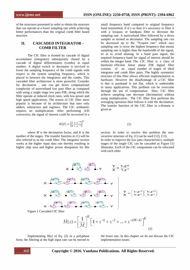
In order to improve the low pass characteristics, multiple
stages of the single CIC can be cascaded as Figure (1)
illustrates. Each of the CIC components can be relocated
with each other.
Figure 1 Cascaded CIC filter
(2)
Implementing H(z) of Eq. (2) in a polyphase
form, the filtering at the high input rate can be moved to
the lower rate. In this chapter we do not discuss the CIC
implementation issues.
www.ijemr.net ISSN (ONLINE): 2250-0758, ISSN (PRINT): 2394-6962
469 Copyright © 2016. Vandana Publications. All Rights Reserved.
2.1 Magnitude characteristic:
The magnitude characteristic of the comb
decimator must satisfy two requirements:
To have a low droop in the frequency band
defined by the passband frequency ωp in order to
preserve the signal after decimation.
To have a high attenuations in so called folding
bands, i. e. the bands around of the zeros of the comb
filter,
(3)
We define the passband frequency as the
frequency where the worst case of passband drop occurs,
(Kwentus, Willson, 1997).
(4)
where R is the decimation stage that follows the
CIC decimation stage, and that is usually much less than
M.
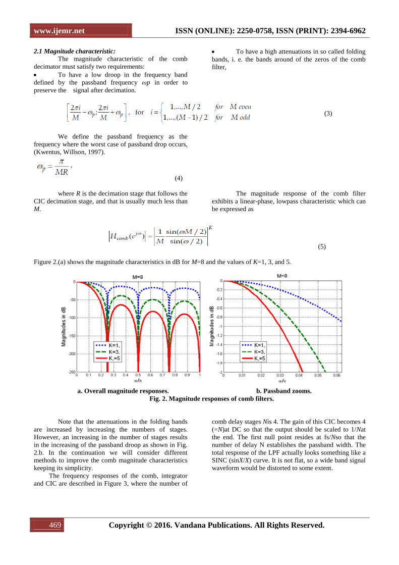
The magnitude response of the comb filter
exhibits a linear-phase, lowpass characteristic which can
be expressed as
(5)
Figure 2.(a) shows the magnitude characteristics in dB for M=8 and the values of K=1, 3, and 5.
a. Overall magnitude responses. b. Passband zooms.
Fig. 2. Magnitude responses of comb filters.
Note that the attenuations in the folding bands
are increased by increasing the numbers of stages.
However, an increasing in the number of stages results
in the increasing of the passband droop as shown in Fig.
2.b. In the continuation we will consider different
methods to improve the comb magnitude characteristics
keeping its simplicity.
The frequency responses of the comb, integrator
and CIC are described in Figure 3, where the number of
comb delay stages Nis 4. The gain of this CIC becomes 4
(=N)at DC so that the output should be scaled to 1/Nat
the end. The first null point resides at fs/Nso that the
number of delay N establishes the passband width. The
total response of the LPF actually looks something like a
SINC (sinX/X) curve. It is not flat, so a wide band signal
waveform would be distorted to some extent.
www.ijemr.net ISSN (ONLINE): 2250-0758, ISSN (PRINT): 2394-6962
470 Copyright © 2016. Vandana Publications. All Rights Reserved.
Figure 3 Comb Filter and its Responces
In this work the designing CIC decimation filter
is performed. The block diagram of the CIC decimation
filter is shown in the figure below.
Figure 4: CIC decimation filter block diagram
Above Figure (4) shows the CIC decimation
filter block diagram. Here in the figure we are designing
CIC decimation filter with the help of Simulink software
in MATLAB. Selecting the parameters for the designing
CIC filter is explained below.
2.2 Implementation of CIC Filters:
Simulink is used to design the systems by using
only block diagram representation. By giving the
parameters we can design the system without writing the
code. The diagrammatic representation of CIC Filters is
shown in the fig. below.
Figure 5 CIC filter circuit diagram using simulink
We can select the components of the system in
simulink library browser, where we have to select CIC
decimation form ‗CIC library‘ and discrete sine wave
from the ‗signal processing block set‘. To see the output
of our system, scope has to be selected from the ‗sinks‘
block.
Here we are sampling the signal with the
frequency of 64 KHz. For example we have 8 KHz sine
wave. We have decimate it at the rate of two. It means in
the input side we have 8 samples (i.e. 64/8=8), at the
output side we should have only 4 samples when we
decimate the signal at the rate of two. The input sine
wave parameters are shown in the Figure 6(a).
www.ijemr.net ISSN (ONLINE): 2250-0758, ISSN (PRINT): 2394-6962
471 Copyright © 2016. Vandana Publications. All Rights Reserved.
After giving the parameters for sine wave we
have to give the parameters for CIC decimation block.
The parameters should be selected according to our
desired output. We have to keep decimation factor as
required i.e. in this project we are keeping decimation
factor as two. This is shown in the Figure 6(b).
Fig (a) source block parameters
Fig (b) CIC function block parameters
Figure 6: The CIC decimation block parameters are shown in the figure below
As shown in the above figure we have given the
parameters for both input signal and CIC decimation
filter. The filter response is shown in the Figure 7 below.
Fig 7 CIC decimation filter response.
Here we are getting a gain of about 12db. This
is the main disadvantage of CIC filters. As a result in the
output there is change in the amplitude i.e. the amplitude
of the output signal is increased. So in order to
compensate this, we will use compensation filter which
will be explained later. After giving the required
parameters to the signal and CIC filter the output of the
filter will be observed in the ‗scope‘. Here in Scope we
have two channels one for input channel and one for
output. The output of the filter is shown in the below
Figure 8.
www.ijemr.net ISSN (ONLINE): 2250-0758, ISSN (PRINT): 2394-6962
472 Copyright © 2016. Vandana Publications. All Rights Reserved.
Figure 8 Output response of CIC filter
Here the below channel shows the input signal
and the upper channel shows the output signal of the
CIC filter. In the input channel we have 8 samples where
as in the output channel we have only 4 channels. So we
can say that it is decimated. But where as the amplitude
of the signal got increased because the gain of the CIC
filter is very high. This can be reduced with the help of
Compensation filter.
III. COMPENSATION FILTER
As discussed earlier the disadvantage of using
CIC filter is it has more gain in the frequency response.
It means the CIC filter frequency response does not have
a wide, flat pass band. To overcome the magnitude
droop, a FIR filter that has a magnitude response that is
the inverse of the CIC filter can be applied to achieve
frequency response correction. Such filters are called
―compensation filters.‖ compensation filter always
operates at the lower rate in a rate conversion design.
One benefit of running the compensation filter at the low
rate is to achieve a more efficient hardware solution, that
is, more time sharing in the compensation FIR filter.
3.1 Mathematical model:
We describe here the compensation filter
(Jovanovic Dolecek & Mitra, 2008) [7] because this
filter satisfies all the properties mentioned previously.
Consider a filter with the Magnitude response
(6) where b is a
integer parameter the corresponding transfer function can be expressed as
(7) Denoting
(8)
we arrive at
(9)
The compensator filter has the scaling factor A
and a single coefficient B which requires only one adder.
Additionally, the compensator can be implemented at a
lower rate after the downsampling by M by making use
of the multirate identity (Jovanovic Dolecek, 2002),
becoming a second order filter
(10)
In that way the filter does not depend on the
decimation factor M but only on the number of
the stages K which defines the parameter b in equation
(7). The system after compensation filter used is shown
in the Figure (9) below.
www.ijemr.net ISSN (ONLINE): 2250-0758, ISSN (PRINT): 2394-6962
473 Copyright © 2016. Vandana Publications. All Rights Reserved.
Figure 9: CIC filter using compensation filter
Compensation filter parameters should be
selected such that the gain of the decimation filter is to
be reduced in a considerable manner. It means we have
gain of the decimation filter about 22dB. So in order to
compensate this we have to design the compensation
filter in the right way. The first thing we have to
consider while designing the decimation filter is no. of
sections in the compensation filter should be equal to the
no. of sections of the decimation filter. It means that no.
of sections that we have taken in the compensation filter
sections should be equal to the no. of sections that we
have taken in the decimation filter section.
In our filter we have taken the no. of sections in
the decimation filter is 4. So we have to take no. of
sections in the compensation filter also as 4. As we have
already decimated the signal by 2, we have to take the
filter type in the compensation filter is single rate. The
parameters of the compensation filter are shown below.
As shown in the figure8 no. of CIC sections are
4 because no. of sections that we have taken in the
decimation filter are 4, so no. of sections in the
Compensation filter are also 4. We have selected the
filter type is single rate because we have already did the
decimation process in the decimation filter. So if we
select decimator in this compensation filter again then
we will get the decimated signal again in the output of
compensation filter. Compensation filter is used just for
compensation purpose but not for decimation purpose.
So we will select filter type as single rate. The filter
specifications parameters selection is shown in Figure
(10).
Figure 10 parameters for selecting the compensation filter
After using the compensation filter the output
amplitude of the signal is reduced to great extent. The
output of the signal without using compensation filter is
12v whereas after using compensation filter is 1.5v as
shown in the simulation results. The frequency response
of the compensation filter is shown Figure 11.
Figure 11 Response of CIC compensation filter
IV. SIMULATION RESULTS
If an 8 KHz signal is applied then the output
contains about 12V.The output of the filter with and
www.ijemr.net ISSN (ONLINE): 2250-0758, ISSN (PRINT): 2394-6962
474 Copyright © 2016. Vandana Publications. All Rights Reserved.
without using the compensation filter is shown in the
below Figure (12). So after using compensation filter,
the amplitude got reduced to 1.4V from 12V
Figure 12: Output responses of CIC filter for 8 KHz signal.
.
V. CONCLUSION
A Cascaded Integrated Comb (CIC) filter has
been designed for efficient transmission multirate
systems. This paper presented different methods that
have been proposed to improve the magnitude
characteristics of the CIC decimator. The CIC filter has
given better result than the traditional FIR filter.
Particularly, the methods are divided into 3 groups based
on the improvement in the passband, stopband or in both
i.e. passband and stopband. The CIC filter is also
implemented using compensation filter, after using this
magnitude is drastically decreases which is shown in the
simulation results. All the codes are done in MATLAB.
REFERENCES
[1] Bijoy Babu, Shesharaman .K.N, ―Power Optimized
Digital Decimation Filter for medical application,
International Conference on Advances in Computing and
Communications 2012.
[2] Pal Alto CA GC4016 Multi-Standard QUAD DDC
Chip, Datasheet, Graychip, USA, Aug., 2000.
[3] Gao, Y. et al. (2000). A Comparison Design of Comb
Decimators for Sigma-Delta Analogto Digital
Converters, Analog Integrated Circuits and Signal
Processing, Vol. 22, No. 1, (January 2000), pp. 51-60,
ISSN 0925-1030
[4] Aboushady, H. et al. (2001). Efficient Polyphase
Decomposition of Comb Decimation Filters in Sigma
Delta Analog-to Digital Converters, IEEE Transactions
on Circuits and Systems II, Vol. 48, No. 10, (October
2001), pp. 898-905, ISSN 1057-7130
[5] Kwentus A. &. Willson, Jr. A, (1997). Application of
Filter Sharpening to Cascaded Integrator-Comb
Decimation Filters, IEEE Transactions on Signal
Processing, Vol. 45, No. 2, (February 1997), pp. 457-
467, ISSN 1057-7122
[6] S. A. White, ―Applications of Distributed Arithmetic
to Digital Signal Processing”, IEEE ASSP Magazine,
Vol.6(3), pp. 4-19, July 1989.
[7] Jovanovic Dolecek, G. & Mitra, S. K. (2008), Simple
Method for Compensation of CIC Decimation Filter,
Electronics Letters, Vol. 44, No. 19, (September 11,
2008), ISSN 0013-5194.
[8] E. B. Hogenauer, ―An Economical Class of Digital
Filters for Decimation and Interpolation'', IEEE. Trans.
Acoust., Speech Signal Processing, Vol. 29, No. 2, pp.
155-162, April 1981.
[9] Xilinx Inc., Virtex-II Platform FPGA Handbook,
2000. [4] Peled and B. Liu, ―A New Hardware
Realization of Digital Filters‖, IEEE Trans. on Acoust.,
Speech, Signal Processing, vol. 22, pp. 456-462, Dec.
1974.
[10] Y.Gao, L. Jia, and H. Tenhunen, ―A fifth-order
comb decimation filter for multistandard transceiver
applications,‖ in Proc. IEEE Int. Symp. Circuits and
Systems, Geneva, Switzerland, May 2000, pp. III-89–III-
92.
[11] Y. Gao, L. Jia, J. Isoaho and H. Tenhunen, ―A
comparison design of comb decimators for sigma-delta
analog-to-digital converters,‖ Analog Integrated
Circuitsand Signal Processing, vol. 22, pp. 51-60,
January 2000.
[12] Gordana Jovanovic Dolecek and Fred Harris,‖ On
Design of Two-Stage CIC Compensation Filter‖, IEEE
International Symposium on Industrial Electronics (ISlE
2009) Seoul Olympic Parktel, Seoul, Korea, pp. 903-
908, July 5-8, 2009
[13] S. K. Mitra, Digital Signal Processing—A
Computer Based Approach, 2nd ed. New York:
McGraw-Hill, 2001.
[14] Nikhil Reddy Karnati,‖A Power Efficient
PolyphaseSharpended CIC Decimation Filter for
SIGMA-DELTA ADCs ―, A Thesis Presented to The
Graduate Faculty of The University of Akron,
December, 2011