doi:10.1016/j.promfg.2016.08.077 Implementation of Conformal Cooling & Topology Optimization in 3D Printed Stainless Steel Porous Structure Injection Molds Suchana A. Jahan 1* , Tong Wu 1 , Yi Zhang 1 , Hazim El-Mounayri 1 , Andres Tovar 1 , Jing Zhang 1 , Douglas Acheson 1 , Razi Nalim 1 , Xingye Guo 1 , Weng Hoh Lee 1 1 IndianaUniversity Purdue University Indianapolis, USA. [email protected],[email protected]Abstract This work presents implementation of numerical analysis and topology optimization techniques for redesigning traditional injection molding tools. Traditional injection molding tools have straight cooling channels, drilled into a solid body of the core and cavity. The cooling time constitutes a large portion of the total production cycle that needs to be reduced as much as possible in order to bring in a significant improvement in the overall business of injection molding industry. Incorporating conformal cooling channels in the traditional dies is a highly competent solution to lower the cooling time as well as improve the plastic part quality. In this paper, the thermal and mechanical behavior of cavity and core with conformal cooling channels are analyzed to find an optimum design for molding tools. The proposed design with conformal cooling channels provides a better alternative than traditional die designs with straight channels. This design is further optimized using thermo-mechanical topology optimization based on a multiscale approach for generating sound porous structures. The implemented topology optimization results in a light-weight yet highly effective die cavity and core. The reduction in weight achieved through the design of dies with porous structures is meant to facilitate the adoption of additive manufacturing for die making by the tooling industry. Keywords: Design, topology optimization, injection molds, conformal cooling, 15-5 PH1 Stainless Steel 1 Introduction Plastic injection molding is a versatile process that uses heat and pressure to convert thermoplastic and thermosetting materials into a variety of complex shapes with high-quality surface finish and dimensional precision (Kauffer, 2011). The design of tooling for plastic injection is considered critically important for the quality of the product that influences the business to a great extent. Traditional * Corresponding author Procedia Manufacturing Volume 5, 2016, Pages 901–915 44th Proceedings of the North American Manufacturing Research Institution of SME http://www.sme.org/namrc Selection and peer-review under responsibility of the Scientific Programme Committee of NAMRI/SME c The Authors. Published by Elsevier B.V. 901
Transcript
doi: 10.1016/j.promfg.2016.08.077
Implementation of Conformal Cooling & Topology Optimization in 3D Printed Stainless Steel Porous
Structure Injection Molds
Suchana A. Jahan1*, Tong Wu1, Yi Zhang1, Hazim El-Mounayri1, Andres Tovar1,Jing Zhang1, Douglas Acheson1, Razi Nalim1, Xingye Guo1, Weng Hoh Lee1
AbstractThis work presents implementation of numerical analysis and topology optimization techniques for redesigning traditional injection molding tools. Traditional injection molding tools have straight cooling channels, drilled into a solid body of the core and cavity. The cooling time constitutes a large portion of the total production cycle that needs to be reduced as much as possible in order to bring in a significant improvement in the overall business of injection molding industry. Incorporating conformal cooling channels in the traditional dies is a highly competent solution to lower the cooling time as well as improve the plastic part quality. In this paper, the thermal and mechanical behavior of cavity and core with conformal cooling channels are analyzed to find an optimum design for molding tools. The proposed design with conformal cooling channels provides a better alternative than traditional die designs with straight channels. This design is further optimized using thermo-mechanical topology optimization based on a multiscale approach for generating sound porous structures. The implementedtopology optimization results in a light-weight yet highly effective die cavity and core. The reduction in weight achieved through the design of dies with porous structures is meant to facilitate the adoption of additive manufacturing for die making by the tooling industry.
1 IntroductionPlastic injection molding is a versatile process that uses heat and pressure to convert thermoplastic
and thermosetting materials into a variety of complex shapes with high-quality surface finish and dimensional precision (Kauffer, 2011). The design of tooling for plastic injection is considered critically important for the quality of the product that influences the business to a great extent. Traditional
* Corresponding author
Procedia Manufacturing
Volume 5, 2016, Pages 901–915
44th Proceedings of the North American ManufacturingResearch Institution of SME http://www.sme.org/namrc
injection molds are limited to manufacture simple geometries such as the solid bodies of core and cavity with straight cooling channels drilled into the cavity wall. Nowadays, Additive Manufacturing (AM)allows manufacturing complicate geometries with the same cost as the simple geometries, which makes possible to adopt many optimization approaches. In this work, the main optimization methods contained are conformal cooling design and thermo-mechanical topology optimization using porous structures. The design of conformal cooling channels, thermo-mechanical topology optimization using porous structures are discussed. In the latter approach, homogenization theory is involved. The final designs can be formatted in STL files and they can be manufactured by Direct Metal Laser Sintering (DMLS)technique.
A microscale material characterization process of 15-5 PH1 stainless steel powder is carried to obtain accurate properties of material that can be incorporated into the numerical and experimental studies of an actual mold created via additive manufacturing method. This also proves the feasibility of the design in microscale. The purpose of this work is to provide a methodology to improve the current injection molding process with limited cost to help manufacturers sustain in the present competitive economy.
2 Literature ReviewThe use of cooling channels conformal to the molding cavity improves the control of mold
temperature and part dimensions. This has been reported by a group at MIT in the 1990’s. (Sachs et al., 2000). Though there have been a series of studies in the area of design and modeling of conformal cooling channels in injection molding tooling, the concept of simulating the designs cannot be rooted back to more than 10 years. Since then, different simulation packages have been used to analyze the tool and channel designs. Moldflow analysis in I-DEAS™ was used by Dimla et al. in 2005 to find the best position of the runner (Dimla et al., 2005). ABM Saifullah and SH Masood analyzed ‘part cooling time’using ANSYS thermal analysis software 2007(Saifullah and Masood, 2007). In 2009, the same group used MPI simulation software for part analysis and compared results for conventional and square section conformal cooling channels; concluding conformal channels render 35% less cooling time than conventional ones(Saifullah et al., 2009). A thermal-structural FEA analysis was performed by Saifullah et al. in 2012 by coupling results from ANSYS Workbench and Autodesk Moldflow Advisor in terms of temperature and stress distribution(Saifullah et al., 2012).
Though there have been many studies in the field of injection mold and their numerical analysis, there is only a limited amount of studies for the design rules for the molds. A simple relationship between 4 parameters for the design of conformal cooling channels using additive manufacturing is found from Mayer (Mayer, 2005). Some research activities show that the use of different cross section for channels other than circular might provide better cooling efficiency. Some current research are being conducted in the analyses of variable distance cooling channels for molding tools (Au and Yu, 2014). In this research a widely accepted design method has been implemented to obtain an optimum design of mold in terms of channel design parameters using CAD and CAE techniques.
Coupled thermo-mechanical analysis has been used in the topology optimization of micro-electro-mechanical-systems (MEMS) in which an electric current causes thermal expansions in the structure(Sigmund, 2001, Du et al., 2009). Several applications have been conducted to maximize the thermal conduction for thermal components including heat sinks for multichip module (Gao et al., 2008) and thermal-fluid electronics micro-channels (Dede, 2012, Koga et al., 2013). Studies that simultaneously consider both mechanical performance (e.g., internal strain energy) and heat conduction are importantfor the design of porous injection molds and dies but these are less frequently found in literature. In recent years, topology optimization using porous structures has been developed with the support of AM to manufacture simple cellular structures (Brackett et al., 2011, Zhang et al., 2015) and practical mechanical components such as bone replacement prototypes (Khanoki and Pasini, 2012). However, these works are limited to simplified 2D models. Considering 3D models have advantages in terms of
Conformal Cooling & Topology Optimization in 3D Printed Injection Molds Jahan et al.
902
accuracy and practical implementation compared with 2D models. In this study 3D analyses are performed using the proposed design method with less computational cost.
15-5 PH1 stainless Steel powder is widely used in the DMLS fabrication. Direct metal laser sintering (DMLS) is a technique that commonly applied to the modern additive manufacturing process. A laser beam is applied to the surface of metal powder bed, adding powders to a designed three dimensional geometry by powder sintering, therefore create a solid printed part. This metal powder would be used in the 3D printing process to create a functionally working injection molding die. Microscale material characterization of the metal powder provides accurate data regarding material properties that can be incorporated in the analysis, which will in turn provide better prediction of the behavior of printed mold in actual manufacturing process.
3 MethodologyIn this paper, a systematic approach is followed to redesign traditional dies (with straight cooling
channels) by incorporating conformal cooling channels as well as porous structure. Earlier investigation of the current authors has recommended 6 designs for conformal cooling channels in a given die. By analyzing these design models for thermal behavior, an optimized structure with conformal cooling channels can be obtained. Next, thermo-mechanical topology optimization using porous structures has been employed to create a light weight and optimum geometry, which can be used for plastic part production in industry. The thermal and mechanical analysis of the solid injection molding tool havebeen performed using structural steel as the die material. On the other hand, as the ultimate mold is to be printed with stainless Steel powder, the topology optimization and homogenization analysis have been done using stainless steel properties for mold material. Moreover microscale characterization is done for stainless steel (15-5 PH1) powder to obtain accurate material properties, which would be used foranalysis of a printed mold in the future.
3.1 Thermal Analysis of Conformal Cooling
To analyze the effect and benefits of conformal cooling channels in injection molds in place of traditional straight drilled channels, six design cases have been chosen for study from an earlier analysis scheme of the same research group.
The CAD models include conformal cooling channels that vary in design from one another in terms of channel diameter (D), pitch distance (P) and channel centerline distance from the mold wall (L). The parameters are illustrated in the schematic diagram in figure 1.
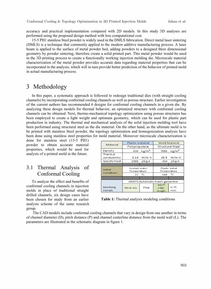
Table 1: Thermal analysis modeling conditions
Conformal Cooling & Topology Optimization in 3D Printed Injection Molds Jahan et al.
903
The die (core and cavity) design is inspired from the existing single cavity tool of the industrial collaborator, which has been used to manufacture a cylindrical plastic bottle cap. Designs are created in Creo parametric and Thermal analysis is performed in ANSYS workbench transient thermal analysis module.Table 1 shows the design parameters of the above discussed design cases and the thermal analysis case setup conditions are mentioned in Table 2.
The design cases being analyzed for both thermal and mechanical performance, it is further reasonable to improve the channel designs with optimal cross sectional shape and study the results. A previous study of the research group has analyzed the effect of various channel cross sections. These included circular, rectangular, square, elliptical and semicircular channel designs, and the rectangular channels provided the best results in terms of cooling time. Hence, the earlier discussed 6 cases have been modified here with rectangular shaped conformal cooling channels and analyzed for performance
Table 2: Design parameters of circular conformal cooling channels in case study
Table 3: Design parameters of rectangular conformal cooling channels in case study
Figure 1: Schematic diagram of a die cavity with parameter definition used in thermal analysis
Conformal Cooling & Topology Optimization in 3D Printed Injection Molds Jahan et al.
904
analysis. These are identified as case 2.1-2.6 for ease of discussion henceforward. The channel cross section size of these cases are shown in Table 3.
3.2 Thermo-Mechanical Analysis of Porous StructuresAfter thermal analysis, the feasibilities of the previously mentioned designs based on the mechanical
properties are investigated. A 110 ton total force is uniformly distributed at the bottom of the cavity and core, 1.31× Pa pressure is applied on the surface of the injected part as the injected pressure. The inlet water temperature of the pipes are assumed to be 22 , 1000W heat flux is imposed on the injected part. Thermal expansion is included.
3.3 Implementation of Thermo-Mechanical PropertiesThe optimization problem addressed in this work involves two length-scales, namely macroscale
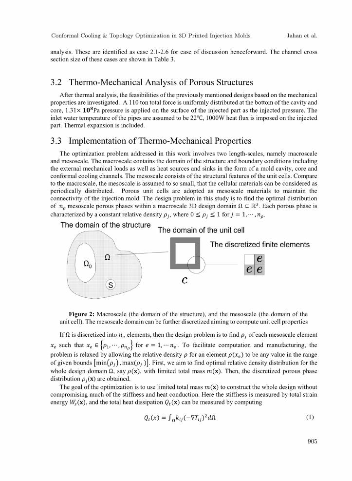
and mesoscale. The macroscale contains the domain of the structure and boundary conditions including the external mechanical loads as well as heat sources and sinks in the form of a mold cavity, core and conformal cooling channels. The mesoscale consists of the structural features of the unit cells. Compare to the macroscale, the mesoscale is assumed to so small, that the cellular materials can be considered as periodically distributed. Porous unit cells are adopted as mesoscale materials to maintain the connectivity of the injection mold. The design problem in this study is to find the optimal distribution of mesoscale porous phases within a macroscale 3D design domain . Each porous phase is characterized by a constant relative density , where 0 1 for = 1, , .
If is discretized into elements, then the design problem is to find of each mesoscale element
such that , , for = 1, . To facilitate computation and manufacturing, the
problem is relaxed by allowing the relative density for an element ( ) to be any value in the range of given bounds min , max ( ) . First, we aim to find optimal relative density distribution for the whole design domain , say ( ), with limited total mass ( ). Then, the discretized porous phase distribution ( ) are obtained.
The goal of the optimization is to use limited total mass ( ) to construct the whole design without compromising much of the stiffness and heat conduction. Here the stiffness is measured by total strain energy ( ), and the total heat dissipation ( ) can be measured by computing( ) = ( ) (1)
Figure 2: Macroscale (the domain of the structure), and the mesoscale (the domain of the unit cell). The mesoscale domain can be further discretized aiming to compute unit cell properties
Conformal Cooling & Topology Optimization in 3D Printed Injection Molds Jahan et al.
905
in ,where indicates thermal conductivity, indicates temperature gradient (Gersborg-Hansen et al., 2006, Bendsøe and Sigmund, 2003). The smallest strain energy and heat dissipation are obtained in a design of solid structure, a reduction of mass causes the increase of these two measurements, which represents the decrease of mold performance. Therefore, the optimization problem statement is defined as minimize the mass subject to the upper bounds of strain energy and heat dissipation. Analogically, with the application of linear FEA, ( ) and ( ) can be discretized to quadratic forms as: = ; = , = ; = , (2)
where and are nodal displacement and nodal temperature respectively; and are assembled stiffness matrix and so called assembled thermal stiffness matrix (Bendsøe and Sigmund, 2003)respectively; and represent the strain-displacement and temperature-temperature gradient relationships respectively. and are homogenized elasticity and thermal conductivity tensor respectively. Both of the total strain energy and heat dissipation will increase while ( ) decreasing. Therefore, the upper bounds need to be defined to control their increment. In addition, obviously, linear elasticity problems and heat conductions follow Hooke's law and Fourier's law respectively:= (Hooke s law),
(3)= ( law),
where and are boundary load and heat flux for , respectively. These equations can be used as equality constraints in the optimization problem. Therefore, the whole thermal-mechanical topology optimization can be formulated as: ( ) (Relaxed porous phase distribution) ( ) = ( ) (Total mass of the macroscale domain) ( ) (Strain energy upper bound) ( ) (Thermal dissipation upper bound) (4) = (Hooke s law)= ( law),where ( ) is a vector containing the relative density for every element and are tolerance factors defined to control the upper bounds of total strain energy and heat dissipation, respectively; ( ) and ( ) indicate the total strain energy and heat dissipation of a component composed of pure solids, respectively. The optimal result of Eq. 4 can be obtained via Globally Convergence Method of Moving Asymptotes (GCMMA) algorithm developed by Svanberg (Svanberg, 2007).
Numerical homogenization is applied by discretizing the domain of the unit cell, in order to obtain and in the foregoing problem. The standard homogenization procedures for elasticity tensor are
well represented in some papers, see e.g. (Bendsøe and Kikuchi, 1988, Guedes and Kikuchi, 1990,Hassani and Hinton, 1998a, Hassani and Hinton, 1998b). The procedure also can be explained using anenergy based approach (Sigmund, 1994). Both of standard homogenization and energy based approach give the same result, which can be written in discretized form (Liu et al., 2002):
Conformal Cooling & Topology Optimization in 3D Printed Injection Molds Jahan et al.
906
= 1| | ( ) ( ) , (5)
where indicates the volume of a mesoscale unit cell, represents the strain-displacement relations of the base cell elements included in , indicates the displacement caused by unit test strains imposed on the base cell elements included in . is a three time three identity matrix (six in 3D). represents the stiffness tensor of a base cell elements included in . Following the analogy relations between linear mechanical and thermal conduction described in the previous section, can be obtained as following equation:
= 1| | ( ) ( ) , (6)
where represents the relations of temperature and temperature gradients, indicates the nodal temperature caused by test temperature gradients included in . represents the thermal conductivity tensor of a base cell element included in . is a two times two identical matrix (3 in 3D). A sequence of unit cells with graded relative densities to obtain the relations between and as well as and using polynomial regression. We assume any homogenized tensor can be written as= + + + , (7)
where ( = 0, 1, 2, 3 ) are constant symmetric matrices. For manufacturing, each element density value is mapped into a set of given density values corresponding to the volume fractions of a family of manufacturable unit cells, while ensuring acceptable small errors with respect to the optimal homogenized and .
In this work, the classification approach is to impose a weighted penalty term on the objective function to restrict the spatial gradient of ( ) as follows:min(1 ) ( ) + ( )where is the weighting factor and is the spatial density distribution. This approach also can be applied to prevent the checkerboard and to prove the well-posed binary design as described in (Bends\oe, 1995) and it is useful when two unit cells are required.
4 Results and DiscussionThe results obtained by following the above mentioned methodology is discussed in the following
sections.
4.1 Results of Thermal AnalysisFigure 3 shows the temperature distribution on the injected plastic at 20 s. This provides a visible
identification about the cooling performance of the 6 design cases.Figure 4 shows the temperature vs. time curve that clearly depicts the cooling pattern of the six cases.
By analyzing the results, it can be stated that a conformal cooling channel with larger diameter is more suitable for the purpose of reducing the cooling time. This is due to the reason that a larger diameter provides larger surface area of the cooling channel, and with a constant value of heat transfer co-efficient, can take away higher amount of heat from the molten plastic and cool more quickly. Design
Conformal Cooling & Topology Optimization in 3D Printed Injection Molds Jahan et al.
907
case 1.5 provides the lowest cooling time as shown in Table 3.This is the channel design with D= 6, P=8 and L= 7mm. It is to be mentioned here that, though case# 1.6 has a larger diameter (D=7mm) than case#1.5, due to its high value of pitch distance, there is less amount of channel inside the mold, resulting in lesser coolant surface area. Moreover, these conformal channel designs provide highly uniform cooling throughout the plastic body( for example, case#1.5 has temperature variance less than 10°C in the plastic body at ejection temperature) compared to the straight drilled channels in traditional dies,which is a highly emphasized requirement in injection molding business. Though it is true that minimum
Figure 3: Temperature Distribution on Injected Plastic part for molds with circular channels
Figure 4: Temperature vs. Time curve for circular channel design case study
Conformal Cooling & Topology Optimization in 3D Printed Injection Molds Jahan et al.
908
possible pitch distance generates uniform cooling in the provided cases, the optimum design needs to take account of all the desired characteristics of a molding tool.
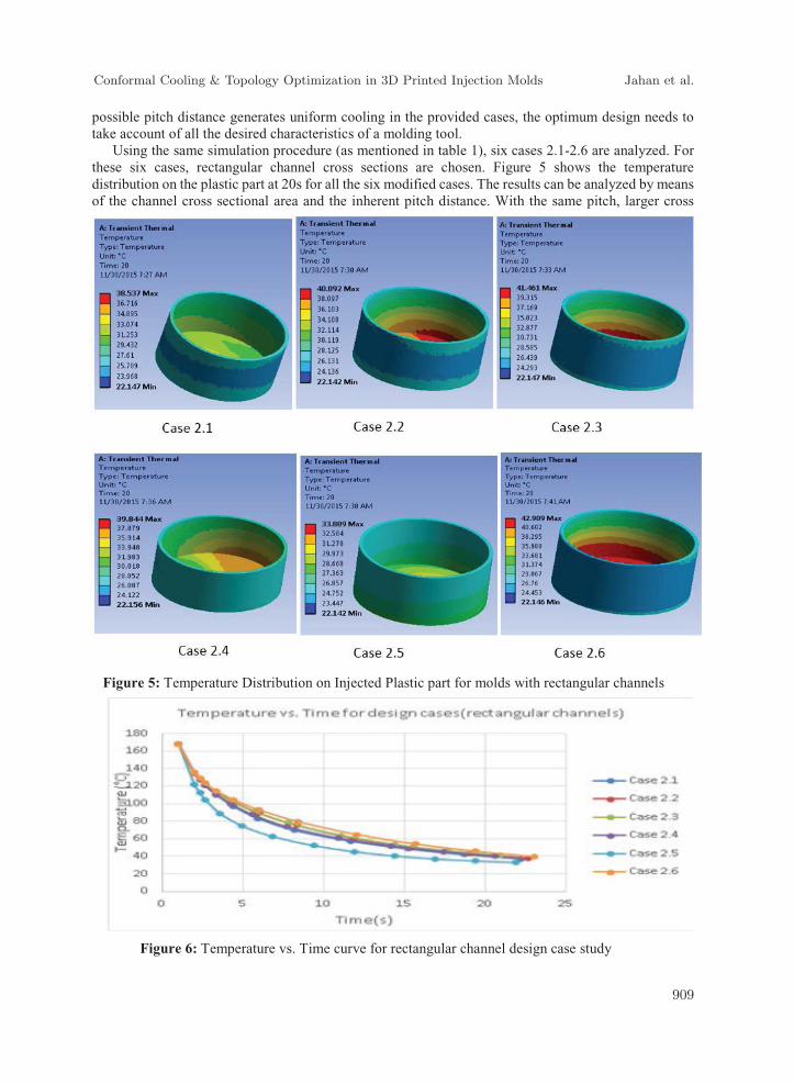
Using the same simulation procedure (as mentioned in table 1), six cases 2.1-2.6 are analyzed. For these six cases, rectangular channel cross sections are chosen. Figure 5 shows the temperature distribution on the plastic part at 20s for all the six modified cases. The results can be analyzed by means of the channel cross sectional area and the inherent pitch distance. With the same pitch, larger cross
Figure 5: Temperature Distribution on Injected Plastic part for molds with rectangular channels
Figure 6: Temperature vs. Time curve for rectangular channel design case study
Conformal Cooling & Topology Optimization in 3D Printed Injection Molds Jahan et al.
909
sectional area provides shorter cooling time. Hence, case#2.5 provides shortest cooling time, i.e., 10.15s, compared to same pitch cases as 1.1 and 1.3. Here, Minimum possible pitch distance generates uniform cooling In the Figure 6, a temperature vs. time curve demonstrates the cooling performance of the modified designs (case 2.1-2.6).
The cooling time for all the 12 cases are shown in Table 4. It is visible that case 2.5 reaches the cooling time earlier than the others. Hence this is to be considered for further topology optimization and homogenization process.
4.2 Results of Mechanical AnalysisThe FEA analysis for mechanical behavior of the CAD model of design cases provided satisfactory
results. The displacements on cavity and core is analyzed for case 1.1-1.6 and best case (from thermal analysis) of the rectangular channel models, i.e.; the case # 2.5. This implies that the designs are feasible to be printed via additive manufacturing, will not generate excessive strain or displacement under high temperature of molten plastic and are viable as molding tools. The results are shown in Table: 5.
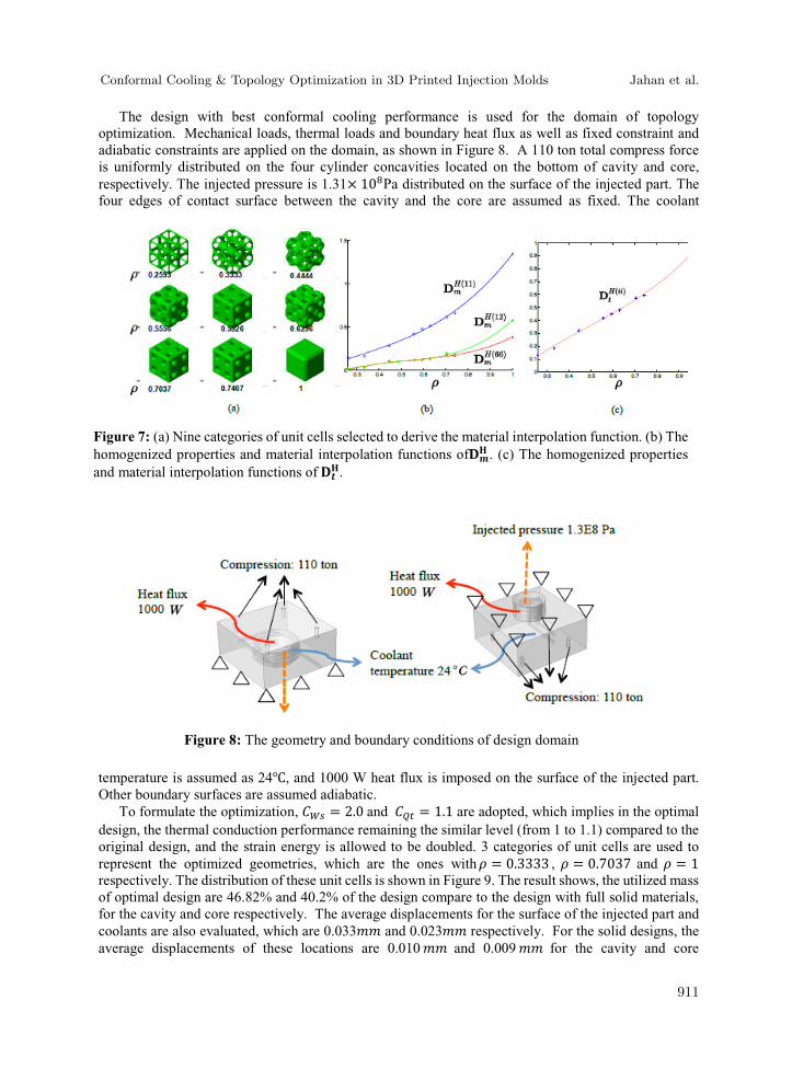
4.3 Results of Topology OptimizationNine categories of unit cells are adopted, which and are computed through homogenization.
All of these unit cells can be represented using a 6× 6 × 6 cubic with iso-surface interpolations, as Figure 7(a) shows. The relative densities for the unit cells are in the range of 0.259 to 1. The results and the fitting curve of the polynomial regression curves are shown in Figure 7(b) and 7(c). Since the select unit cells are orthotropic, only ( ), ( ) and ( ) in elasticity stiffness tensor and any ( ) in the thermal conductivity tensor are required to be computed. These curves will be adopted as material interpolation function in the topology optimization procedures.
Table 4: Cooling time for design case studies (both circular and rectangular channels)
Table 5: Average displacements on core and cavity for design cases
Conformal Cooling & Topology Optimization in 3D Printed Injection Molds Jahan et al.
910
The design with best conformal cooling performance is used for the domain of topology optimization. Mechanical loads, thermal loads and boundary heat flux as well as fixed constraint and adiabatic constraints are applied on the domain, as shown in Figure 8. A 110 ton total compress force is uniformly distributed on the four cylinder concavities located on the bottom of cavity and core, respectively. The injected pressure is 1.31× 10 Pa distributed on the surface of the injected part. The four edges of contact surface between the cavity and the core are assumed as fixed. The coolant
temperature is assumed as 24 , and 1000 W heat flux is imposed on the surface of the injected part. Other boundary surfaces are assumed adiabatic.
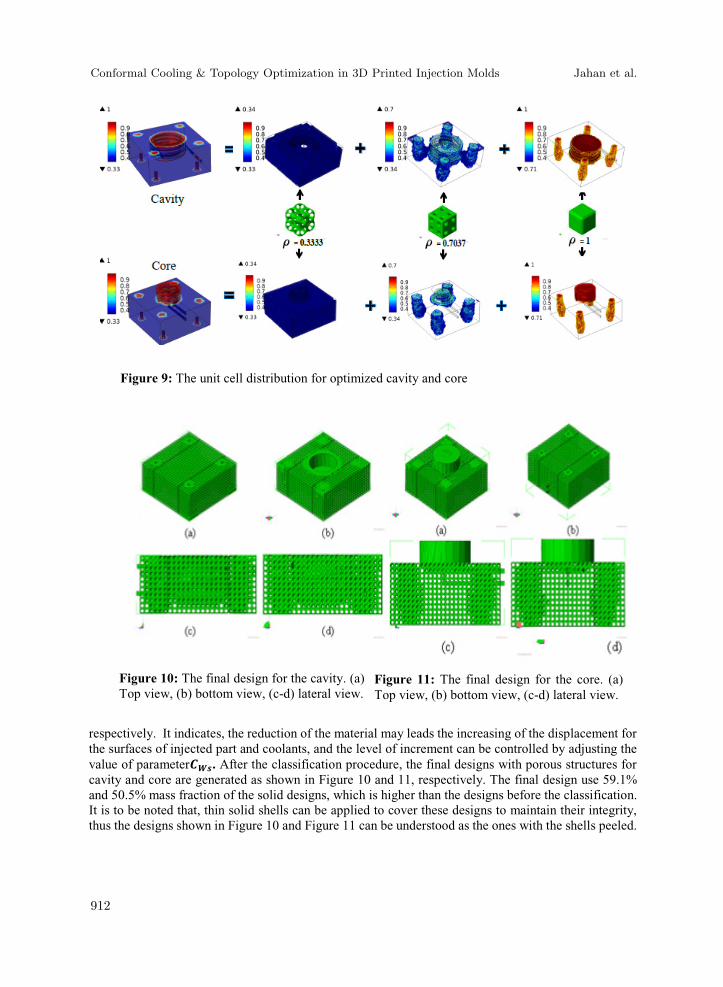
To formulate the optimization, = 2.0 and = 1.1 are adopted, which implies in the optimal design, the thermal conduction performance remaining the similar level (from 1 to 1.1) compared to the original design, and the strain energy is allowed to be doubled. 3 categories of unit cells are used to represent the optimized geometries, which are the ones with = 0.3333 , = 0.7037 and = 1respectively. The distribution of these unit cells is shown in Figure 9. The result shows, the utilized mass of optimal design are 46.82% and 40.2% of the design compare to the design with full solid materials, for the cavity and core respectively. The average displacements for the surface of the injected part and coolants are also evaluated, which are 0.033 and 0.023 respectively. For the solid designs, the average displacements of these locations are 0.010 and 0.009 for the cavity and core
Figure 7: (a) Nine categories of unit cells selected to derive the material interpolation function. (b) The homogenized properties and material interpolation functions of . (c) The homogenized properties and material interpolation functions of .
Figure 8: The geometry and boundary conditions of design domain
Conformal Cooling & Topology Optimization in 3D Printed Injection Molds Jahan et al.
911
respectively. It indicates, the reduction of the material may leads the increasing of the displacement forthe surfaces of injected part and coolants, and the level of increment can be controlled by adjusting the value of parameter . After the classification procedure, the final designs with porous structures for cavity and core are generated as shown in Figure 10 and 11, respectively. The final design use 59.1% and 50.5% mass fraction of the solid designs, which is higher than the designs before the classification. It is to be noted that, thin solid shells can be applied to cover these designs to maintain their integrity, thus the designs shown in Figure 10 and Figure 11 can be understood as the ones with the shells peeled.
Figure 9: The unit cell distribution for optimized cavity and core
Figure 11: The final design for the core. (a) Top view, (b) bottom view, (c-d) lateral view.
Figure 10: The final design for the cavity. (a) Top view, (b) bottom view, (c-d) lateral view.
Conformal Cooling & Topology Optimization in 3D Printed Injection Molds Jahan et al.
912
5 Conclusion and Work in ProgressAn existing injection mold from Hewitt Molding (industrial partner in this research) is redesigned
in this work for better performance and lower printing cost. Using optimum design methodologies for conformal cooling channels and topology optimization and material homogenization technique, a porous structure of injection mold with conformal cooling channel design has been created. Rectangular channel design (6.5mm x 4.3 mm) with a pitch distance 8mm and mold wall to channel centerline distance 7mm provided optimum performance in terms of cooling time and uniform cooling. Topology optimization renders a 59.1% and 50.5% porous structure for the cavity and core respectively. In addition to the optimization, microscale characterization is performed on stainless steel powders to an aid to validation process and experimental studies of 3D printed molds. By doing this, the result can be further applied to computer added design, process optimization etc. Specifically in this project, the obtained material properties are going to be used to provide better prediction of the behavior of printed mold in actual manufacturing process.
In order to further improve the accuracy of thermo-mechanical analysis, better material property estimation is needed. Scanning electron microscopy (SEM) and energy dispersive X-ray spectroscopy(EDS) techniques have been used to observe the microstructure of the powders and parts. A Rockwell micro hardness test of the surface of printed parts has been done. These experimental analysis aims at obtaining accurate material properties as hardness, yield strength, elasticity etc. to further apply in topology optimization process as mentioned earlier. The microstructure, composition of powders and printed part, as well as micro hardness of printed part surface are investigated. Diameter of the spherical particle are in the range of 15 ~ 70 m. Figure 12 and 13 below shows the scanning electron microscopic image of 15-5 stainless powder of magnification of 800 (Figure12) and 9500 (Figure 13). The powders are mostly spherical shaped in general, with a few particles irregular shape. Particle size are in a range from 15 to 70 micrometer in diameter. Particles grouped pairwise can be observed from figure 12 top right region by a neck between two or more particles, this is due to temperature induced sintering during the treatment of powder production, or due to partial of the powders are recycled from previous laser sintering process. Figure13 shows the surface texture of a particle at higher magnification. Grain structure of stainless steel can be observed from this figure, with grain size of about 2~3 micrometer.
The Rockwell hardness was measured according to ASTM 18E-15, with load of 150 kgf. The measured hardness is 42.9±0.3 HRC. The indentation mark of the HRC is given in Figure 14. According to EOS 2009 materials data, the HRC value for EOS stainless-steel PH1 is about 40, after age hardening. The reference HRC result is in consistent with this test at 150 kgf load, which is HRC standard load. Further studies are currently ongoing to extract exact material properties as yield strength, thermal
Figure 12: SEM image of the 15-5 PH1 powders
Figure 13: Surface texture of 15-5 PH1 powder
Figure 14: Indentation mark during the Rockwell Hardness Measurement
Conformal Cooling & Topology Optimization in 3D Printed Injection Molds Jahan et al.
913
conductivity etc. to provide more insight and accuracy into the numerical studies regarding thermal and mechanical behavior.
Further experimental analysis is going on to use more accurate material characteristics in order toapply those in topology optimization process. The researchers are looking forward to implementing their methodology and optimization algorithm for general benefit of injection molding industry in future.
References
Au, K. & Yu, K. 2014. Variable Distance Adjustment for Conformal Cooling Channel Design in Rapid Tool. Journal of Manufacturing Science and Engineering, 136, 044501.
Bendsøe, M. P. 1995. Optimization of structural topology, shape, and material. Springer.Bendsøe, M. P. & Kikuchi, N. 1988. Generating optimal topologies in structural design using a
homogenization method. Computer methods in applied mechanics and engineering, 71, 197-224.
Bendsøe, M. P. & Sigmund, O. 2003. Topology optimization: theory, method and applications, Springer.Brackett, D., Ashcroft, I. & Hague, R. Topology optimization for additive manufacturing. Proceedings
of the Solid Freeform Fabrication Symposium, Austin, TX, 2011. 348-362.Dede, E. M. 2012. Optimization and design of a multipass branching microchannel heat sink for
electronics cooling. Journal of Electronic Packaging, 134, 041001.Dimla, D., Camilotto, M. & Miani, F. 2005. Design and optimisation of conformal cooling channels in
injection moulding tools. Journal of Materials Processing Technology, 164, 1294-1300.Du, Y., Luo, Z., Tian, Q. & Chen, L. 2009. Topology optimization for thermo-mechanical compliant
actuators using mesh-free methods. Engineering Optimization, 41, 753-772.Gao, T., Zhang, W., Zhu, J., Xu, Y. & Bassir, D. 2008. Topology optimization of heat conduction
problem involving design-dependent heat load effect. Finite Elements in Analysis and Design,44, 805-813.
Gersborg-Hansen, A., Bendsøe, M. P. & Sigmund, O. 2006. Topology optimization of heat conduction problems using the finite volume method. Structural and multidisciplinary optimization, 31,251--259.
Guedes, J. M. & Kikuchi, N. 1990. Preprocessing and postprocessing for materials based on the homogenization method with adaptive finite element methods. Computer Methods in Applied Mechanics and Engineering, 83, 143-198.
Hassani, B. & Hinton, E. 1998a. A review of homogenization and topology optimization. I. Homogenization theory for media with periodic structure. Comput. Struct. (UK), 69, 707-17.
Hassani, B. & Hinton, E. 1998b. A review of homogenization and topology optimization. II. Analytical and numerical solution of homogenization equations. Comput. Struct. (UK), 69, 719-38.
Kauffer, P. H. 2011. Injection Molding: Process, Design and Applications.Khanoki, S. A. & Pasini, D. 2012. Multiscale design and multiobjective optimization of orthopedic hip
implants with functionally graded cellular material. Journal of biomechanical engineering,134, 031004.
Koga, A. A., Lopes, E. C. C., Nova, H. F. V., De Lima, C. R. & Silva, E. C. N. 2013. Development of heat sink device by using topology optimization. International Journal of Heat and Mass Transfer, 64, 759-772.
Liu, S. T., Cheng, G. D., Gu, Y. & Zheng, X. G. 2002. Mapping method for sensitivity analysis of composite material property. Structural and multidisciplinary optimization, 24, 212--217.
Conformal Cooling & Topology Optimization in 3D Printed Injection Molds Jahan et al.
914
Mayer, S. 2005. Optimised mould temperature control procedure using DMLS. EOS Whitepaper, EOS GmbH Ltd, 1-10.
Sachs, E., Wylonis, E., Allen, S., Cima, M. & Guo, H. 2000. Production of injection molding tooling with conformal cooling channels using the three dimensional printing process. Polymer Engineering & Science, 40, 1232-1247.
Saifullah, A. & Masood, S. Finite element thermal analysis of conformal cooling channels in injection moulding. Proceedings of the 5th Australasian congress on applied mechanics, 2007. Engineers Australia, 337.
Saifullah, A., Masood, S. & Sbarski, I. New cooling channel design for injection moulding. Proceedings of the World Congress on Engineering, 2009.
Saifullah, A., Masood, S. & Sbarski, I. 2012. Thermal–structural analysis of bi-metallic conformal cooling for injection moulds. The International Journal of Advanced Manufacturing Technology, 62, 123-133.
Sigmund, O. 1994. Materials with prescribed constitutive parameters: an inverse homogenization problem. Int. J. Solids Struct. (UK), 31, 2313-29.
Sigmund, O. 2001. Design of multiphysics actuators using topology optimization--Part I: One-material structures. Computer methods in applied mechanics and engineering, 190, 6577--6604.
Svanberg, K. 2007. MMA and GCMMA-two methods for nonlinear optimization.Zhang, P., Toman, J., Yu, Y., Biyikli, E., Kirca, M., Chmielus, M. & To, A. C. 2015. Efficient Design-
Optimization of Variable-Density Hexagonal Cellular Structure by Additive Manufacturing: Theory and Validation. Journal of Manufacturing Science and Engineering, 137, 021004.
Conformal Cooling & Topology Optimization in 3D Printed Injection Molds Jahan et al.