123 | Page IMPLEMENTATION OF MULTILEVEL INVERTER FOR SOLAR POWERED INDUSTRIAL UPS SYSTEMS R.Uthirasamy 1 , P.Ravi Kumar 2 ,V.J.Vijayalakshmi 3 ,J.Karpagam 4 1,2,3,4 Department of EEE, KPR Institute of Engineering & Technology, ABSTRACT The unbalanced load becomes non-linear, a the neutral of the loads are available. The four leg inverter produces the three output voltages independently with one additional leg. The main feature of a three phase inverter with an additional neutral leg, its ability to deal with load unbalance in a system. Also, in three leg Voltage Source Inverters (VSI) neutral current handling is one of the series problem under unbalanced load conditions. The goal of the three phase four leg inverter is to maintain the desired sinusoidal output voltage waveform for all loading conditions and transients. The neutral connection is present to handle the ground current due to unbalanced loads. This four wire inverter system is most applicable for UPS applications. In four leg inverter the voltage stress and harmonic issues is similar to that of conventional three wire VSI. To minimize the voltage stress and harmonics Cascaded Multilevel Inverter (CMLI) is introduced. In this paper, the four wire inverter is compared (without filter and with filter circuit) with multilevel inverter according to their switches, voltage balancing condition and Total Harmonic Distortion (THD). The entire system is simulated using MATLAB/SIMULINK. Key words:Four wire Voltage Source Inverter, Cascaded Multilevel inverter (CMLI), Total Harmonic Distortion. I. INTRODUCTION In power electronics conversion systems, AC power sources often feeds a star connected three-phase load with accessible neutral terminal. The currents flowing on each phase are generally not balanced. So, a connection to the neutral terminal should be provided by adding an extra wire to the inverter [1]. Compared to a three-phase three-wire system, it provides three dimensional controls by not using isolation transformer. Four-Leg converters are better actuating converter choice for unbalanced load conditions due to the introduction of the fourth leg. Essentially, the three phase currents/voltages can be regulated independently using the four-leg converters, which find applications in load balancing, distortion mitigation, and fault toleration [2].Multilevel inverters are being increasingly used in high power applications due to their superior performance over two level inverters. The main advantages of MLI are: higher output voltage with same device rating and lower harmonic content. The general structure of the multilevel VSI is to synthesize a sinusoidal output voltage from several levels of dc voltages; it can therefore be described as a Voltage Synthesizer. In conventional VSI, the maximum voltage output is determined by the blocking capability of each device whereas in a multilevel structure, the voltage stress on each switching device can be reduced in proportional to the number of voltage levels, thus this inverter can handle higher voltages. Another significant advantage is that several voltage levels leads to a better and
Transcript
123 | P a g e
IMPLEMENTATION OF MULTILEVEL INVERTER FOR
SOLAR POWERED INDUSTRIAL UPS SYSTEMS
R.Uthirasamy1, P.Ravi Kumar
2,V.J.Vijayalakshmi
3,J.Karpagam
4
1,2,3,4Department of EEE, KPR Institute of Engineering & Technology,
ABSTRACT
The unbalanced load becomes non-linear, a the neutral of the loads are available. The four leg inverter produces
the three output voltages independently with one additional leg. The main feature of a three phase inverter with
an additional neutral leg, its ability to deal with load unbalance in a system. Also, in three leg Voltage Source
Inverters (VSI) neutral current handling is one of the series problem under unbalanced load conditions. The goal
of the three phase four leg inverter is to maintain the desired sinusoidal output voltage waveform for all loading
conditions and transients. The neutral connection is present to handle the ground current due to unbalanced
loads. This four wire inverter system is most applicable for UPS applications. In four leg inverter the voltage
stress and harmonic issues is similar to that of conventional three wire VSI. To minimize the voltage stress and
harmonics Cascaded Multilevel Inverter (CMLI) is introduced. In this paper, the four wire inverter is compared
(without filter and with filter circuit) with multilevel inverter according to their switches, voltage balancing
condition and Total Harmonic Distortion (THD). The entire system is simulated using MATLAB/SIMULINK.
Key words:Four wire Voltage Source Inverter, Cascaded Multilevel inverter (CMLI), Total
Harmonic Distortion.
I. INTRODUCTION
In power electronics conversion systems, AC power sources often feeds a star connected three-phase load with
accessible neutral terminal. The currents flowing on each phase are generally not balanced. So, a connection to
the neutral terminal should be provided by adding an extra wire to the inverter [1]. Compared to a three-phase
three-wire system, it provides three dimensional controls by not using isolation transformer. Four-Leg
converters are better actuating converter choice for unbalanced load conditions due to the introduction of the
fourth leg. Essentially, the three phase currents/voltages can be regulated independently using the four-leg
converters, which find applications in load balancing, distortion mitigation, and fault toleration [2].Multilevel
inverters are being increasingly used in high power applications due to their superior performance over two
level inverters.
The main advantages of MLI are: higher output voltage with same device rating and lower harmonic content.
The general structure of the multilevel VSI is to synthesize a sinusoidal output voltage from several levels of dc
voltages; it can therefore be described as a Voltage Synthesizer. In conventional VSI, the maximum voltage
output is determined by the blocking capability of each device whereas in a multilevel structure, the voltage
stress on each switching device can be reduced in proportional to the number of voltage levels, thus this inverter
can handle higher voltages. Another significant advantage is that several voltage levels leads to a better and
124 | P a g e
more sinusoidal voltage waveform. As a result, a lower Total Harmonic Distortion (THD) is obtained [3-5]. This
paper is organized with the following sections: Section-I shows the introduction of MLI. The circuit description
of four wire inverter and MLI are addressed in Section-II. In Section-III the comparison and switching
combinations of inverters are shown with its output voltages. Complete reviews of three phase four wire inverter
and single H-bridge MLI simulation results are obtained in Section-IV. Finally, the conclusion is presented in
Section-V.
II. CIRCUIT DESCRIPTION OF INVERTER
2.1Four wire inverter
The two main ways for neutral wire connection are
Inverter with split dc link capacitors
Inverter with fourth (neutral) leg
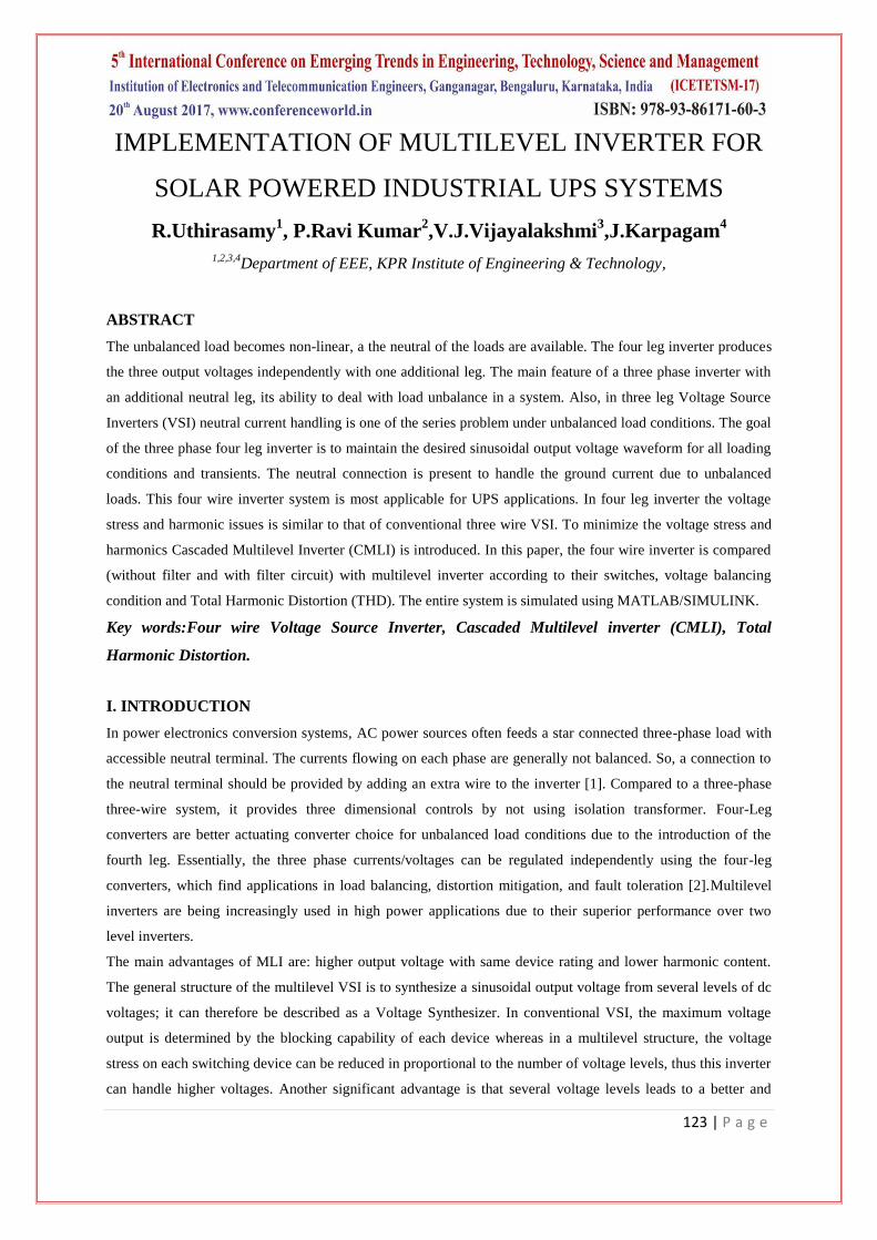
The first way is the simple method but it generates the zero sequence harmonics. When the load is unbalanced
or non-linear a high voltage ripple over supply capacitor is produced by neutral currents. The second way is it
requires additional power switches and is quite complex control strategy. It offers different advantages such as
increased maximum output voltage value, reduction of neutral currents and the possibility of neutral point
voltage control shown in Fig. 1.
Fig.1. Three phase four wire inverter with split dc link capacitor
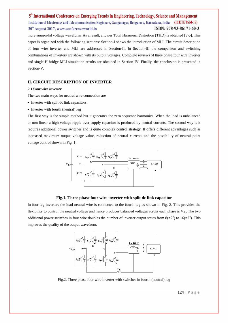
In four leg inverters the load neutral wire is connected to the fourth leg as shown in Fig. 2. This provides the
flexibility to control the neutral voltage and hence produces balanced voltages across each phase is Vdc. The two
additional power switches in four wire doubles the number of inverter output states from 8(=23) to 16(=2
4). This
improves the quality of the output waveform.
Fig.2. Three phase four wire inverter with switches in fourth (neutral) leg
125 | P a g e
2.2 Multi level inverter
A cascaded multilevel inverter is a power electronic device built to synthesize a desired AC voltage from several
levels of DC voltages [6]. The most common topologies of multilevel inverters are the following: the Diode-
Clamped Multilevel Inverter (DCMLI), the Flying Capacitor Multilevel Inverter (FCMLI) and the Cascaded
Multilevel Inverter (CMLI). CMLI topology is the most attractive. It requires the least number of components. It
has simple circuit layout and modular in structure. Furthermore, this type of topology is free of DC voltage
balancing issue that occurred in DCMLI and FCMLI topologies. Multilevel voltage source inverters offer
several advantages compared to their conventional counterparts. Synthesizing the sinusoidal ac output terminal
voltage from several levels of dc voltages, staircase waveforms can be produced with low harmonic distortion
and thereby reducing the filter requirements [7-10].
Here new converter structure, CMLI with separate dc sources (SDC‟s) is introduced. This new converter can
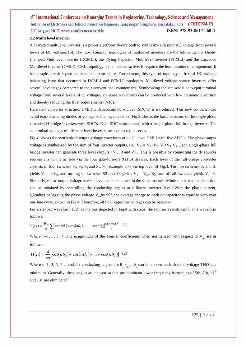
avoid extra clamping diodes or voltage balancing capacitors. Fig.3. shows the basic structure of the single phase
cascaded H-bridge inverters with SDC‟s. Each SDC is associated with a single-phase full-bridge inverter. The
ac terminal voltages of different level inverters are connected in series.
Fig.4. shows the synthesized output voltage waveform of an 11-level CMLI with five SDC‟s. The phase output
voltage is synthesized by the sum of four inverter outputs, i.e., Van = V1+V2+V3+V4+V5. Each single-phase full
bridge inverter can generate three level outputs +Vdc, 0 and -Vdc. This is possible by connecting the dc sources
sequentially to the ac side via the four gate-turn-off (GTO) devices. Each level of the full-bridge converter
consists of four switches S1, S2, S3 and S4. For example take the top level of Fig.3. Turn on switches S1 and S4
yields V1 = +Vdc and turning on switches S2 and S3 yields V1= -Vdc. By turn off all switches yields V1= 0.
Similarly, the ac output voltage at each level can be obtained in the same manner. Minimum harmonic distortion
can be obtained by controlling the conducting angles at different inverter levels.With the phase current,
ia,leading or lagging the phase voltage Vanby 90°, the average charge to each dc capacitor is equal to zero over
one line cycle, shown in Fig.4. Therefore, all SDC capacitor voltages can be balanced.
For a stepped waveform such as the one depicted in Fig.4 with steps, the Fourier Transform for this waveform
follows:
n
tnnnn
VtV
n
dc
sincos...coscos
4)( 821 (1)
Where n=1, 3, 5, 7…the magnitudes of the Fourier coefficients when normalized with respect to Vdc
are as
follows:
821 cos...coscos4
nnnn
nH (2)
Where n=1, 3, 5, 7… and the conducting angles are θ1,θ
2,…,θ
s can be chosen such that the voltage THD is a
minimum. Generally, these angles are chosen so that pre-dominant lower frequency harmonics of 5th, 7th, 11th
and 13th
are eliminated.
126 | P a g e
Fig.3. Single phase Cascaded H-bridge inverter
Fig.4. Output voltage waveform for 11-level CMLI
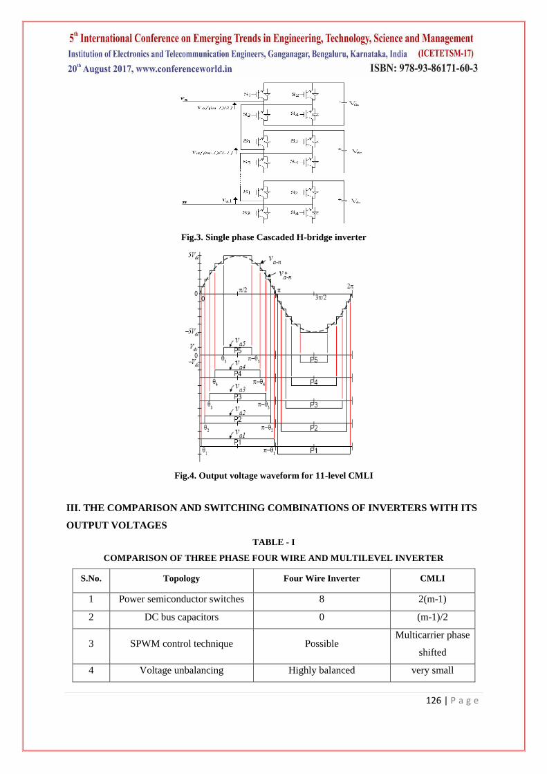
III. THE COMPARISON AND SWITCHING COMBINATIONS OF INVERTERS WITH ITS
OUTPUT VOLTAGES
TABLE - I
COMPARISON OF THREE PHASE FOUR WIRE AND MULTILEVEL INVERTER
S.No. Topology Four Wire Inverter CMLI
1 Power semiconductor switches 8 2(m-1)
2 DC bus capacitors 0 (m-1)/2
3 SPWM control technique Possible Multicarrier phase
shifted
4 Voltage unbalancing Highly balanced very small
127 | P a g e
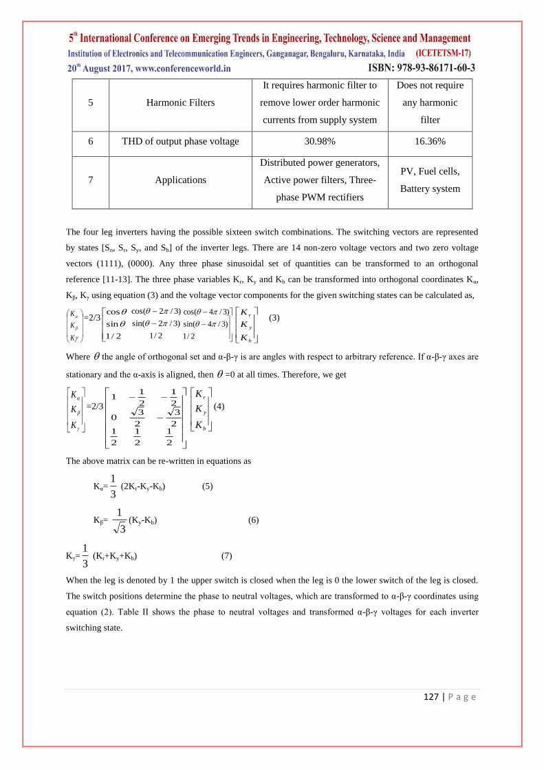
5 Harmonic Filters
It requires harmonic filter to
remove lower order harmonic
currents from supply system
Does not require
any harmonic
filter
6 THD of output phase voltage 30.98% 16.36%
7 Applications
Distributed power generators,
Active power filters, Three-
phase PWM rectifiers
PV, Fuel cells,
Battery system
The four leg inverters having the possible sixteen switch combinations. The switching vectors are represented
by states [Sn, Sr, Sy, and Sb] of the inverter legs. There are 14 non-zero voltage vectors and two zero voltage
vectors (1111), (0000). Any three phase sinusoidal set of quantities can be transformed to an orthogonal
reference [11-13]. The three phase variables Kr, Ky and Kb can be transformed into orthogonal coordinates Kα,
Kβ, Kγ using equation (3) and the voltage vector components for the given switching states can be calculated as,
K
K
K=2/3
2/1
sin
cos
2/1
)3/2sin(
)3/2cos(
2/1
)3/4sin(
)3/4cos(
b
y
r
K
K
K (3)
Where the angle of orthogonal set and α-β-γ is are angles with respect to arbitrary reference. If α-β-γ axes are
stationary and the α-axis is aligned, then =0 at all times. Therefore, we get
K
K
K
=2/3
2
1
2
1
2
12
3
2
30
2
1
2
11
b
y
r
K
K
K
(4)
The above matrix can be re-written in equations as
Kα=3
1 (2Kr-Ky-Kb) (5)
Kβ= 3
1(Ky-Kb) (6)
Kγ=3
1 (Kr+Ky+Kb) (7)
When the leg is denoted by 1 the upper switch is closed when the leg is 0 the lower switch of the leg is closed.
The switch positions determine the phase to neutral voltages, which are transformed to α-β-γ coordinates using
equation (2). Table II shows the phase to neutral voltages and transformed α-β-γ voltages for each inverter
switching state.
128 | P a g e
TABLE - II
SWITCHING COMBINATION AND OUTPUT VOLTAGES FOR 3-PHASE 4-WIRE INVERTER
SWITCHING
STATE
Vrn
Vyn
Vbn
Vα
Vβ
Vγ
0000 0 0 0 0 0 0
0001 0 0 Vdc -1/3Vdc -1/√3Vdc 1/3Vdc
0010 0 Vdc 0 - 1/3Vdc 1/√3Vdc 1/3Vdc
0011 0 Vdc Vdc - 2/3Vdc 0 2/3Vdc
0100 Vdc 0 0 2/3Vdc 0 1/3Vdc
0101 Vdc 0 Vdc 1/3Vdc - 1/√3Vdc 2/3Vdc
0110 Vdc Vdc 0 1/3Vdc 1/√3Vdc 2/3Vdc
0111 Vdc Vdc Vdc 0 0 Vdc
1000 - Vdc - Vdc - Vdc 0 0 -Vdc
1001 - Vdc - Vdc 0 -1/3Vdc - 1/√3Vdc - 2/3Vdc
1010 - Vdc 0 - Vdc - 1/3Vdc 1/√3Vdc - 2/3Vdc
1011 - Vdc 0 0 - 2/3Vdc 0 -1/3Vdc
1100 0 - Vdc - Vdc 2/3Vdc 0 - 2/3Vdc
1101 0 - Vdc 0 1/3Vdc - 1/√3Vdc -1/3Vdc
1110 0 0 - Vdc 1/3Vdc 1/√3Vdc -1/3Vdc
1111 0 0 0 0 0 0
A multilevel converter has several advantages over a conventional converter that uses high switching frequency
pulse width modulation (PWM). The attractive features of a multilevel converter can be briefly summarized as
follows.
Staircase waveform quality: Multilevel converters not only generate the output voltages with low distortion
but also it reduces the dv/dt stresses. Thus Electro-Magnetic Compatibility (EMC) problems can be reduced.
Common-mode (CM) voltage: Multilevel converters produce smaller CM voltage with the stress in the
bearings of a motor connected to a multilevel motor drive can be reduced. Furthermore, CM voltage can be
eliminated by using advanced modulation strategies.
Switching frequency: Multilevel converters can operate at both fundamental switching frequency and high
switching frequency PWM.
The following are the main advantages and drawbacks of the cascaded H-bridge MLI:
Advantages:
The number of possible output voltage levels is more than twice the number of dc sources (m = 2s + 1).
The series of H-bridges makes for modularized layout and packaging. This will enable the manufacturing
process to be done more quickly and cheaply.
Drawbacks:
Separate dc sources are required for each of the H-bridge for the conversion of the active power which limits
its use.
129 | P a g e
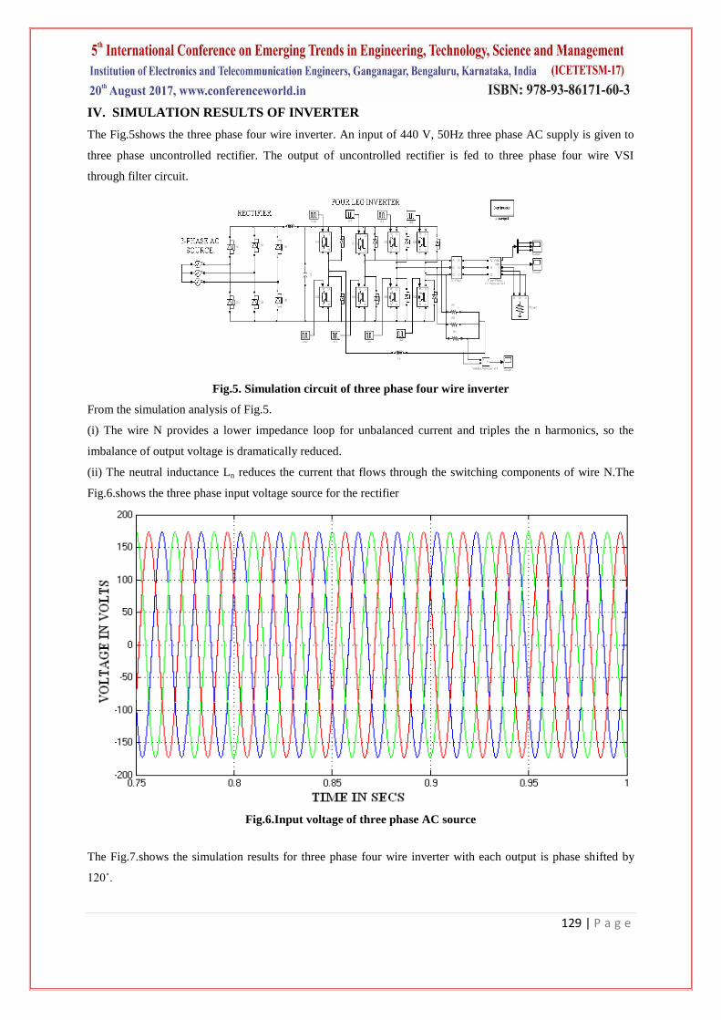
IV. SIMULATION RESULTS OF INVERTER
The Fig.5shows the three phase four wire inverter. An input of 440 V, 50Hz three phase AC supply is given to
three phase uncontrolled rectifier. The output of uncontrolled rectifier is fed to three phase four wire VSI
through filter circuit.
Fig.5. Simulation circuit of three phase four wire inverter
From the simulation analysis of Fig.5.
(i) The wire N provides a lower impedance loop for unbalanced current and triples the n harmonics, so the
imbalance of output voltage is dramatically reduced.
(ii) The neutral inductance Ln reduces the current that flows through the switching components of wire N.The
Fig.6.shows the three phase input voltage source for the rectifier
Fig.6.Input voltage of three phase AC source
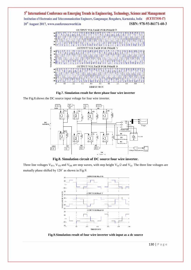
The Fig.7.shows the simulation results for three phase four wire inverter with each output is phase shifted by
120˚.
130 | P a g e
Fig.7. Simulation result for three phase four wire inverter
The Fig.8.shows the DC source input voltage for four wire inverter.
Fig.8. Simulation circuit of DC source four wire inverter.
Three line voltages VRY, VYB and VBR are step waves, with step height Vdc/2 and Vdc. The three line voltages are
mutually phase shifted by 120˚ as shown in Fig.9.
Fig.9.Simulation result of four wire inverter with input as a dc source
131 | P a g e
The neutral voltage waveform for four wire inverter as shown in Fig.10.
Fig.10. Neutral voltage of four wire inverter
The Fig.11.shows the THD level for four wire inverter and the distortion is about 30.98% without any filter
component.
Fig.11. THD for four wire inverter without filter component
By using filter component the level THD is reduced and the THD is 3.92% is shown in Fig.12.
Fig.12. THD level for four wire inverter with filter component
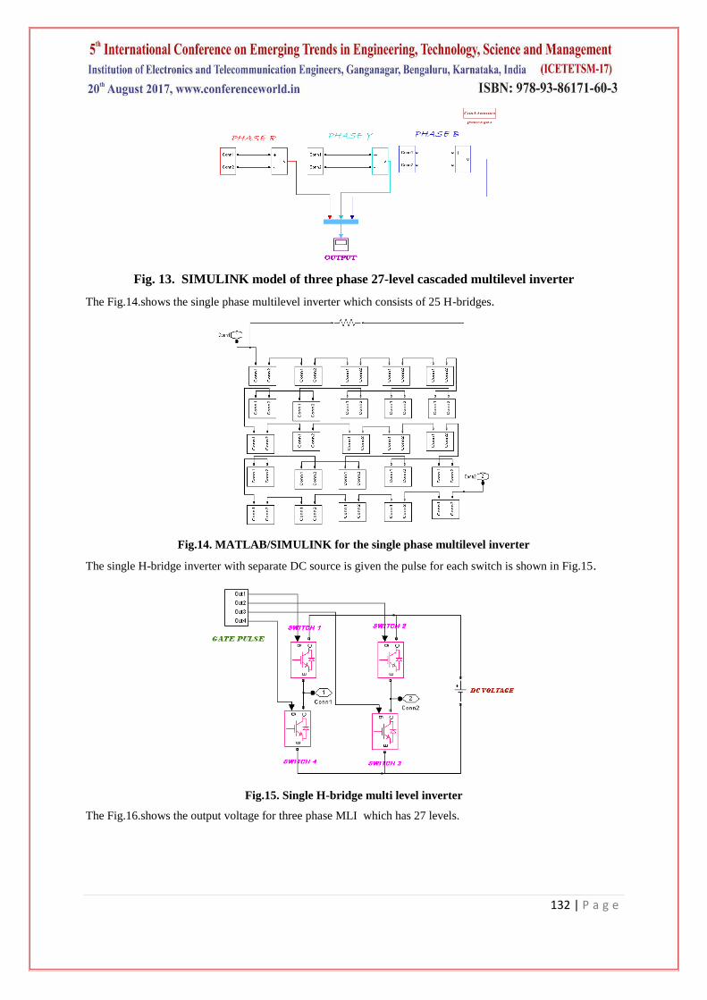
The Fig.13.shows the MATLAB/SIMULINK for three phase cascaded multilevel inverter for 27 level.
132 | P a g e
Fig. 13. SIMULINK model of three phase 27-level cascaded multilevel inverter
The Fig.14.shows the single phase multilevel inverter which consists of 25 H-bridges.
Fig.14. MATLAB/SIMULINK for the single phase multilevel inverter
The single H-bridge inverter with separate DC source is given the pulse for each switch is shown in Fig.15.
Fig.15. Single H-bridge multi level inverter
The Fig.16.shows the output voltage for three phase MLI which has 27 levels.
133 | P a g e
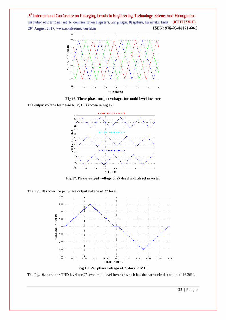
Fig.16. Three phase output voltages for multi level inverter
The output voltage for phase R, Y, B is shown in Fig.17.
Fig.17. Phase output voltage of 27-level multilevel inverter
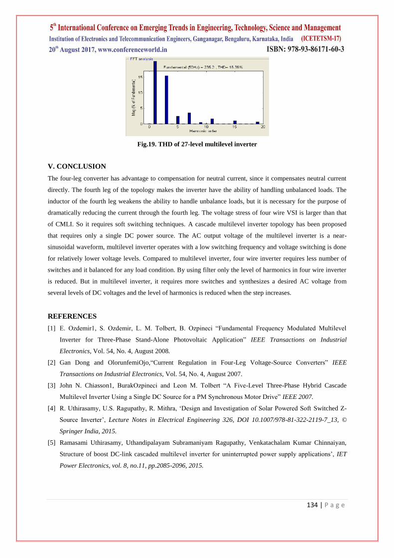
The Fig. 18 shows the per phase output voltage of 27 level.
Fig.18. Per phase voltage of 27-level CMLI
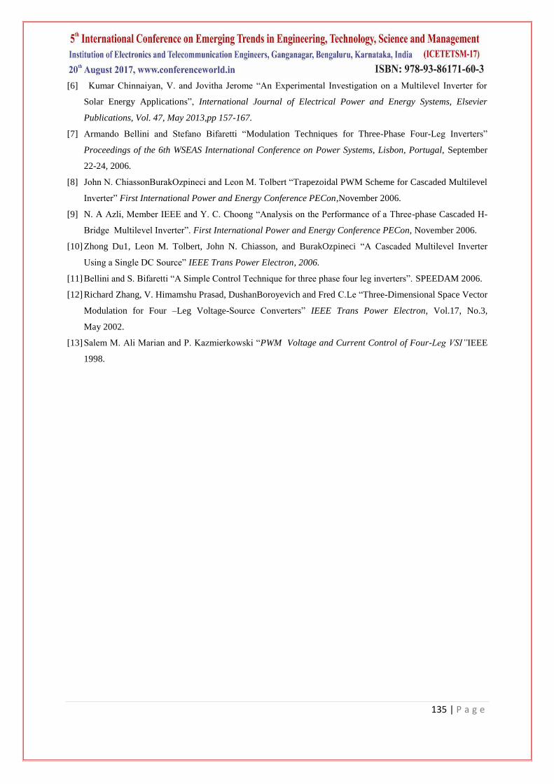
The Fig.19.shows the THD level for 27 level multilevel inverter which has the harmonic distortion of 16.36%.
134 | P a g e
Fig.19. THD of 27-level multilevel inverter
V. CONCLUSION
The four-leg converter has advantage to compensation for neutral current, since it compensates neutral current
directly. The fourth leg of the topology makes the inverter have the ability of handling unbalanced loads. The
inductor of the fourth leg weakens the ability to handle unbalance loads, but it is necessary for the purpose of
dramatically reducing the current through the fourth leg. The voltage stress of four wire VSI is larger than that
of CMLI. So it requires soft switching techniques. A cascade multilevel inverter topology has been proposed
that requires only a single DC power source. The AC output voltage of the multilevel inverter is a near-
sinusoidal waveform, multilevel inverter operates with a low switching frequency and voltage switching is done
for relatively lower voltage levels. Compared to multilevel inverter, four wire inverter requires less number of
switches and it balanced for any load condition. By using filter only the level of harmonics in four wire inverter
is reduced. But in multilevel inverter, it requires more switches and synthesizes a desired AC voltage from
several levels of DC voltages and the level of harmonics is reduced when the step increases.
REFERENCES
[1] E. Ozdemir1, S. Ozdemir, L. M. Tolbert, B. Ozpineci “Fundamental Frequency Modulated Multilevel
Inverter for Three-Phase Stand-Alone Photovoltaic Application” IEEE Transactions on Industrial
Electronics, Vol. 54, No. 4, August 2008.
[2] Gan Dong and OlorunfemiOjo,“Current Regulation in Four-Leg Voltage-Source Converters” IEEE
Transactions on Industrial Electronics, Vol. 54, No. 4, August 2007.
[3] John N. Chiasson1, BurakOzpineci and Leon M. Tolbert “A Five-Level Three-Phase Hybrid Cascade
Multilevel Inverter Using a Single DC Source for a PM Synchronous Motor Drive” IEEE 2007.
[4] R. Uthirasamy, U.S. Ragupathy, R. Mithra, „Design and Investigation of Solar Powered Soft Switched Z-