IAEA-TECDOC-1455 Implementation of the International Code of Practice on Dosimetry in Radiotherapy (TRS 398): Review of testing results Final report of the Coordinated Research Projects on Implementation of the International Code of Practice TRS 398 at Secondary Standards Dosimetry Laboratories and Hospitals June 2005
Transcript
IAEA-TECDOC-1455
Implementation of the InternationalCode of Practice on Dosimetry in
Radiotherapy (TRS 398):Review of testing resultsFinal report of the Coordinated Research Projects on
Implementation of the International Code of Practice TRS 398 atSecondary Standards Dosimetry Laboratories and Hospitals
June 2005
The originating Section of this publication in the IAEA was:
Dosimetry and Medical Radiation Physics Section International Atomic Energy Agency
Wagramer Strasse 5 P.O. Box 100
A-1400 Vienna, Austria
IMPLEMENTATION OF THE INTERNATIONAL CODE OF PRACTICE ON DOSIMETRY IN RADIOTHERAPY (TRS 398): REVIEW OF TESTING RESULTS
IAEA, VIENNA, 2005 IAEA-TECDOC-1455 ISBN 92–0–105005–4
In 2000 the IAEA published the Code of Practice (CoP) entitled Absorbed Dose Determination in External Beam Radiotherapy: An International Code of Practice for Dosimetry Based on Standards of Absorbed Dose to Water (IAEA Technical Reports Series No. 398). This CoP recommends procedures to determine absorbed dose to water from measurements made with an ionization chamber in photon, electron, proton and heavy-ion beams. The implementation of TRS 398 decreases the uncertainty in the dosimetry of radiotherapy beams and provides the Member States with a unified and consistent framework, which had not existed before. TRS 398 is gradually replacing the CoPs published earlier by the IAEA such as TRS 277 and TRS 381, which most Member States use today, and evidence of improvement in practical dosimetry is necessary to advocate its implementation. TRS 398 is addressed both to standards dosimetry laboratories, especially Secondary Standards Dosimetry Laboratories (SSDLs), and to hospitals. To provide practical guidance to SSDLs on the calibrations and dissemination of calibration coefficients to hospitals in accordance with TRS 398, a coordinated research project (CRP E2.10.04) was established. Furthermore, to provide guidelines for practical implementation of TRS 398 for the hospital users in Member States, the coordinated research project (CRP E2.40.09) was extended. The main goal of the extended project was to test the procedures recommended in TRS 398 for different types of radiation beams and ionization chambers, and to compare the results with those obtained following other major dosimetry protocols that are in use all over the world. The testing of TRS 398 was performed by a group of medical physicists from hospitals and various institutions around the world. The two CRPs, CRP E2.10.04 and the extension of CRP E2.40.09, were conducted for three and two years respectively. The present publication is a compilation of the results and findings by the participants of both CRPs and is addressed to medical physicists at SSDLs and hospitals who seek guidance in the implementation of TRS 398 for radiotherapy dosimetry. The IAEA wishes to express its gratitude to all authors and reviewers of this publication as listed at the end of the TECDOC. The final editorial contribution of M. Saiful Huq from the University of Pittsburgh Cancer Institute, Pittsburgh, Pennsylvania, USA is gratefully acknowledged. The IAEA officers responsible for this publication were S. Vatnitsky and A. Meghzifene of the Division of Human Health.
EDITORIAL NOTE
The use of particular designations of countries or territories does not imply any judgement by the publisher, the IAEA, as to the legal status of such countries or territories, of their authorities and institutions or of the delimitation of their boundaries.
The mention of names of specific companies or products (whether or not indicated as registered) does not imply any intention to infringe proprietary rights, nor should it be construed as an endorsement or recommendation on the part of the IAEA.
2. IMPLEMENTATION OF THE INTERNATIONAL CODE OF PRACTICE TRS 398 FOR ABSORBED DOSE DETERMINATION IN EXTERNAL BEAM RADIOTHERAPY BASED ON STANDARDS OF ABSORBED DOSE TO WATER..............................................3 2.1. Realization and dissemination of standards of absorbed dose to water ...............................3
2.2. Recommendation for the implementation of TRS 398 at SSDLs........................................8 2.2.1. General ......................................................................................................................8 2.2.2. Realization and dissemination of absorbed dose to water at 60Co
gamma ray beam......................................................................................................11
3. OVERVIEW OF FORMULATION OF VARIOUS INTERNATIONAL AND NATIONAL CODES OF PRACTICE ..............................................................................................................19 3.1. General...............................................................................................................................19 3.2. High-energy photon and electron beams ...........................................................................19
3.3. Protocols for low-energy kilovoltage X ray beams ...........................................................25 3.3.1. Formalism based on NK calibrations: IAEA TRS 277 ............................................25 3.3.2. Formalism based on ND,w calibrations: IAEA TRS 398 ..........................................26
3.4. Protocols for medium-energy kilovoltage X ray beams ....................................................26 3.4.1. Formalism based on NK calibrations .......................................................................26 3.4.2. Formalism based on ND,w calibrations: IAEA TRS 398 ..........................................27
3.5. Protons and heavy-ions......................................................................................................28 3.5.1. IAEA TRS 398 ........................................................................................................28 3.5.2. ICRU 59 ..................................................................................................................28 3.5.3. The CoP from the German Cancer Research Centre ...............................................29
3.6. Parallelism between the Codes of Practice ........................................................................30 3.6.1. High-energy photon and electron beams .................................................................30 3.6.2. Kilovoltage X ray beams .........................................................................................30
4.2.1. Ionization chambers.................................................................................................32 4.2.2. Phantoms and chamber sleeves ...............................................................................32
4.3. Beam quality specification.................................................................................................32 4.4. Determination of absorbed dose to water ..........................................................................32
4.4.1. Experimental method...............................................................................................32 4.4.2. Reference conditions ...............................................................................................32 4.4.3. Determination of absorbed dose to water under reference conditions.....................34
5.2.1. Ionization chambers.................................................................................................37 5.2.2. Phantoms and chamber sleeves ...............................................................................37
5.3. Beam quality specification.................................................................................................37 5.4. Determination of absorbed dose to water ..........................................................................40
5.4.1. Experimental method...............................................................................................40 5.4.2. Reference conditions ...............................................................................................40 5.4.3. Determination of absorbed dose to water under reference conditions.....................41
5.5. Results................................................................................................................................42 5.5.1. Chamber calibrated in 60Co gamma ray beam.........................................................42 5.5.2. Chamber calibrated in high-energy photon beams ..................................................46
6.2.1. Ionization chambers.................................................................................................49 6.2.2. Phantoms and chamber sleeves ...............................................................................49
6.3. Beam quality specification.................................................................................................49 6.4. Determination of absorbed dose to water ..........................................................................50
6.4.1. Experimental method...............................................................................................50 6.4.2. Absorbed dose determinations in plastic and water phantoms................................50 6.4.3. Determination of absorbed dose to water under reference conditions.....................50
6.5. Results................................................................................................................................54 6.5.1. Calibration of electron beams using cross-calibrated plane-parallel chambers,
TRS 398 vs TRS 381...............................................................................................54 6.5.2. Calibration of electron beams using ND,w calibrated plane-parallel chambers,
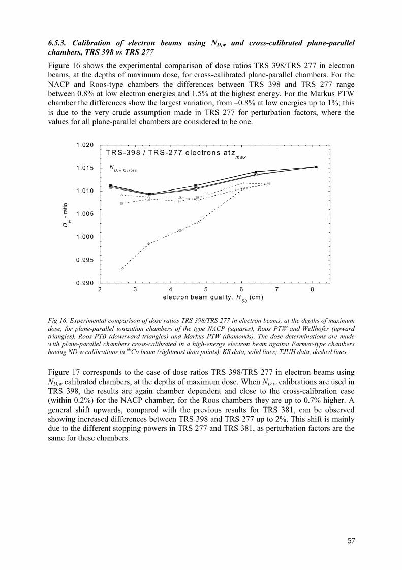
TRS 398 vs TRS 381...............................................................................................56 6.5.3. Calibration of electron beams using ND,w and cross-calibrated plane-parallel
chambers, TRS 398 vs TRS 277..............................................................................57 6.5.4. Calibration of electron beams using ND,w calibrated cylindrical chambers,
TRS 398 vs TG-51...................................................................................................58 6.5.5. Calibration of electron beams using ND,w calibrated plane-parallel chambers,
TRS 398 vs TG-51...................................................................................................59 6.5.6. Calibration of electron beams using cross- calibrated plane-parallel chambers,
TRS 398 vs TG-51...................................................................................................59 6.5.7. Calibration of electron beams using a plane-parallel chamber and a cylindrical
chamber, TRS 398 vs DIN 6800-2 ..........................................................................60 6.5.8. Calibration of electron beams using a chamber calibrated in high-energy
electron beams .........................................................................................................61 6.5.9. Dose determination in plastic phantoms in high energy electron beams:
comparison of calibrations in water and Plastic WaterTM phantoms using TRS 398 .........................................................................................................61
7. EXPERIMENTAL COMPARISON: LOW-ENERGY KILOVOLTAGE X RAY BEAMS......64 7.1. General...............................................................................................................................64 7.2. Dosimetry equipment.........................................................................................................64
7.2.1. Ionization chambers.................................................................................................64 7.2.2. Phantoms and chamber sleeves ...............................................................................64
7.3. Beam quality specification.................................................................................................64 7.4. Determination of absorbed dose to water ..........................................................................65
7.4.1. Experimental method...............................................................................................65 7.4.2. Reference conditions ...............................................................................................66 7.4.3. Determination of absorbed dose to water under reference conditions.....................68
7.5. Results................................................................................................................................68 7.5.1. Absorbed dose to water calibration coefficients obtained from QKN , in low-
energy X ray beams .................................................................................................68
7.5.2. Absorbed dose to water calibration coefficients directly provided by PTB in low energy X ray beams .................................................................................................68
8. EXPERIMENTAL COMPARISON: MEDIUM-ENERGY KILOVOLTAGE X RAY BEAMS...........................................................................................................................71 8.1. General...............................................................................................................................71 8.2. Dosimetry equipment.........................................................................................................71
8.2.1. Ionization chambers.................................................................................................71 8.2.2. Phantoms and chamber sleeves ...............................................................................72
8.3. Beam quality specification.................................................................................................72 8.4. Determination of absorbed dose to water ..........................................................................72
8.4.1. Reference conditions ...............................................................................................72 8.4.2. Determination of absorbed dose to water under reference conditions.....................72
9.2.1. Ionization chambers.................................................................................................75 9.2.2. Phantoms and chamber sleeves ...............................................................................75
9.3. Beam quality specification.................................................................................................75 9.4. Determination of absorbed dose to water ..........................................................................76
9.4.1. Experimental method...............................................................................................76 9.4.2. Reference conditions ...............................................................................................76 9.4.3. Determination of absorbed dose to water under reference conditions.....................76
10.2.1. Ionization chambers...............................................................................................79 10.2.2. Phantoms and chamber sleeves..............................................................................79
10.3. Beam quality specification.................................................................................................79 10.4. Determination of absorbed dose to water ..........................................................................80
10.4.1. Experimental method.............................................................................................80 10.4.2. Reference conditions .............................................................................................80 10.4.3. Determination of absorbed dose to water under reference conditions...................81
APPENDIX A: EXAMPLE OF UNCERTAINITY ANALYSIS FOR ABSORBED DOSE TO WATER CALIBRATION FOR 60Co ...........................................................................83
APPENDIX B. CALIBRATION PROCEDURE USED AT THE LNHB ............................................93
REFERENCES.......................................................................................................................................97 IAEA PUBLICATIONS ON RADIATION DOSIMETRY AND MEDICAL RADIATION PHYSICS .....................................................................................................99 CONTRIBUTORS TO DRAFTING AND REVIEW..........................................................................101
1. INTRODUCTION
The development of primary standards of absorbed dose to water for high-energy photon and electron beams, and the opportunity to use these standards as the basis for the dosimetry of kilovoltage X ray beams, as well as that of proton and heavy-ion beams, offer the possibility of establishing a coherent dosimetry system based on standards of absorbed dose to water for practically all radiotherapy beams. Many Primary Standards Dosimetry Laboratories (PSDLs) already provide calibrations in terms of absorbed dose to water at the radiation quality of 60Co gamma rays. Some laboratories have extended calibrations to high-energy photon and electron beams or are in the process of developing the necessary techniques for these modalities. Supported by the recommendations in 1996 of the IAEA Standing Advisory Group, the “Scientific Committee of the IAEA/World Health Organization (WHO) Secondary Standards Dosimetry Laboratories (SSDL) Network”, a coordinated research project (CRP E2.40.09) was undertaken during 1997–1999 with the task of producing a new International Code of Practice (CoP) based on standards of absorbed dose to water. In 2000 the task was completed by the publication of the CoP entitled Absorbed Dose Determination in External Beam Radiotherapy: An International Code of Practice for Dosimetry Based on Standards of Absorbed Dose to Water (IAEA Technical Reports Series No. 398) [1]. Its goal is to advise users on calibration of radiotherapy photon, electron, proton and heavy-ion beams using an ionization chamber calibrated in terms of absorbed dose to water. The recommendations of TRS 398 are addressed both to standards dosimetry laboratories, especially SSDLs, and to hospitals. The calibration of ionization chambers in terms of absorbed dose to water is realized at SSDLs and disseminated to hospitals. It is important that the SSDLs that have been calibrating ionization chambers in terms of air kerma get specific guidance on the realization of the new quantity, absorbed dose to water in a 60Co gamma ray beam. For radiation beam qualities other than 60Co (i.e. X rays, high energy photons, electrons, protons and heavy ions), the SSDLs are presently not able to realize the absorbed dose to water based quantities. This situation is not expected to change significantly in the next 10 years. To provide practical guidance to SSDLs on the calibrations and dissemination of calibration coefficients to hospitals in accordance with TRS 398, a coordinated research project (CRP E2.10.04) was conducted over 3 years. Initially, the CRP included one PSDL and 4 SSDLs1. At the user level, the adoption of the new TRS 398 CoP will introduce differences in the values of the absorbed dose to water because of replacing the widespread use of various CoPs issued by the IAEA in the eighties and nineties (i.e. TRS 277, TRS 381), or the use of its data in many other protocols. The differences in the value of the absorbed dose to water are expected to depend on the type and quality of the beam and on the type of ionization chamber. The magnitude of these differences needs to be determined prior to the clinical implementation of TRS 398. For 60Co gamma radiation, which is generally better characterized than other modalities, beam calibrations based on the two different standards, Kair and Dw, differ typically by 1%2 (TRS 398 dose values are higher compared to the values
1 The CRP was intiated with four participants from SSDLs, but only two completed the work. 2 It should be noted that since the measurements of this CRP were completed, many standards laboratories have revised their
standards for air kerma by about 0.8%. Beam calibrations based on the revised standards for air kerma and wD will bring the absorbed dose to water at 60Co into agreement closer than 1%.
1
determined with air kerma-based protocols). For other radiation qualities larger differences are expected, which will always include the systematic difference for 60Co. In order to provide guidelines for practical implementation of TRS 398 for the hospital users in Member States, the coordinated research project (CRP E2.40.09) was extended and its scientific scope was expanded to include the task of analysing and quantifying possible differences with the recommendations of other dosimetry protocols. The main goal of the extended project was testing the procedures recommended in TRS 398 for different types of radiation beams and ionization chambers, and comparison of these results with those obtained with the major protocols that are in use all over the world. The recommendations in the Code of Practice TRS 398 will gradually replace those of TRS 277 [2] and TRS 381 [3], which most Member States use today, and evidence of improvement in practical dosimetry is necessary to advocate implementation of the new CoP. The coordinated research project E2.40.09 operated between 2000 and 2002 during which time one consultant’s meeting was held in Vienna in 2000. At this meeting the consultants decided on a set of measurements, measurement procedures and techniques to be performed to test the implementation of TRS 398 in a hospital environment. It was also decided that measurements be performed in 60Co gamma ray beams, high-energy photon and electrons beams, medium and low energy kilovoltage X ray beams, and proton and heavy ion beams. The present publication is a compilation of the results and findings of the participants from both CRPs. The purpose of this report is twofold: to provide guidelines to SSDLs on how to establish a standard of absorbed dose to water in a 60Co gamma ray beam and to provide guidelines to clinical physicists about the changes that can be expected when TRS 398 is adopted in a hospital environment in place of their currently used CoP based on air kerma standards. Section 2 focuses on the framework of the international measurement system, the realization and dissemination of absorbed dose to water standards at the PSDLs and SSDLs and the recommendations given by the participants of CRP E2.10.04 for the implementation of TRS 398 at the SSDLs. Section 3 provides a summary of information in the various CoPs that needs to be considered to gain insight into the comparison of data used in the determination of absorbed dose to water using TRS 398 and existing CoPs. Sections 4-9 present results of measurements made in 60Co beams, low and medium energy X ray beams, high-energy photon and electron beams, and proton and heavy-ion beams by the participants of CRP E2.40.09. These results are grouped in a tabular and graphical form for different ionization chambers and beam energies showing the expected differences in absorbed dose determination between TRS 398 and other previously existing CoPs. It is strongly recommended that when implementing the recommendations of TRS 398 in the clinic, the user should compare measured values of absorbed dose determined using TRS 398 and the protocol currently in use in the clinic with the corresponding values presented in this report. If the change in absorbed dose measured by the user lies outside the expected values presented in this publication, the user should look for an explanation of this discrepancy before implementing TRS 398 clinically.
2
2. IMPLEMENTATION OF THE INTERNATIONAL CODE OF PRACTICE TRS 398 FOR ABSORBED DOSE DETERMINATION IN EXTERNAL BEAM
RADIOTHERAPY BASED ON STANDARDS OF ABSORBED DOSE TO WATER
The international measurement system (SI, for Système International) for radiation metrology, provides a mechanism for ensuring traceability and consistency of radiation measurements by providing users with calibrated radiation measuring instruments that are traceable to primary standards. The SI consists of the Bureau International des Poids et Mesures (BIPM), national PSDLs, SSDLs and end-users. The IAEA and WHO have contributed significantly to strengthen the SI by setting up a network of SSDLs to ensure traceability of measurements, particularily for countries that are not members of the Metre Convention. By 2004, the SSDL network included 75 laboratories and 6 SSDL national organizations in 63 Member States. The SSDL network also included 20 affiliated members, for example, the BIPM, several PSDLs, the International Commission for Radiation Units and Measurements (ICRU), the International Organization of Medical Physics (IOMP) and several other international organizations [4].
2.1. Realization and dissemination of standards of absorbed dose to water
2.1.1. Primary standards dosimetry laboratories
2.1.1.1. 60Co gamma ray beam
Major developments at PSDLs in the 1990s have led to well established procedures for the determination of standards of absorbed dose to water based on water and graphite calorimetry, ionometry and chemical dosimetry [1,5].
Air kerma standards have a very long history of comparisons. Although primary standards of absorbed dose to water were first established and compared in the 1970’s, the new generation of absorbed dose to water standards were only completed and compared in the 1990’s [6-8]. The results of comparisons of standards of absorbed dose to water at the BIPM in the 60Co beam, shown in TRS 398 [1], have been updated with the most recent results and now include fourteen PSDLs. The agreement is well within the relative standard uncertainty given by the PSDLs (see Fig. 1, reproduced from ref [9]).
2.1.1.2. Other radiation beams
For high-energy photon beams, only a few PSDLs [1] currently provide calibration coefficients of ionization chambers in terms of absorbed dose to water at selected beam qualities. On the other hand, for high-energy electron beams, only a very few PSDLs can provide calibration coefficients of ionization chambers in terms of absorbed dose to water [10, 11]. For low and medium energy X rays, only one PSDL currently provides calibration coefficient for ionization chambers in terms of absorbed dose to water for a specified set of beam qualities [12].
3
BIPM.RI(I)-K4Degrees of equivalence for absorbed dose to water
-30
-25
-20
-15
-10
-5
0
5
10
15
20
25
PTB
BN
M-L
NH
B
EN
EA
BE
V
AR
PA
NS
A
NIS
T
NR
C
LSD
G
NM
i
ME
TAS
VN
IIFTR
I
OM
H
DN
MI /
10-3
Fig. 1. Results of comparisons of standards of absorbed dose to water in the 60Co beam. The
NMID , value is the difference of the comparison from the reference value of 1. The uncertainty bars represent the expanded uncertainties (k = 2) of the comparison result (see ref [9] for more details). The squares indicate results more than ten years old that are in the process of being renewed.
2.1.2. Secondary standards dosimetry laboratories In 2003, a survey was conducted among all SSDLs of the IAEA/WHO network on the status of absorbed dose to water calibrations and implementation of TRS 398 [13]. Half the SSDLs reported that TRS 398 is used in hospitals in their countries. An additional 20% have stated that plans are under way to use TRS 398 in the hospitals. For 60Co beams, absorbed dose to water calibrations are provided by SSDLs in all countries where TRS 398 is reported to be in use. SSDLs disseminate calibration coefficients for absorbed dose to water only to those hospitals that are properly prepared to utilize it. This is consistent with an IAEA recommendation published in the SSDL Newsletter No. 34 [14] that explicitly advises SSDLs not to disseminate absorbed dose to water calibrations to hospitals that are not prepared or have not yet adopted a dosimetry protocol based on standards of absorbed dose to water.
2.1.2.1. Development of absorbed dose to water calibrations for 60Co at SSDLs
During 1980-1990, the first decade that followed the establishment of the network, the activities of the IAEA towards the SSDLs aimed mainly at the establishment of the necessary laboratory infrastructures and training of staff in calibration techniques, especially in developing countries. Since then, many laboratories have joined the network and the scope of their work is expanding continuously. To ensure that the services provided by SSDL members to end-users follow internationally accepted standards, the IAEA has set up two different comparison programmes. One programme relies on the IAEA/WHO postal TLD service [15] and the other uses dose comparisons based on measurements made with ionization chambers [16] to help the SSDLs verify the integrity of their national standards and the procedures used for the transfer of the standards to the end-users. The IAEA-SSDL comparisons include comparisons of 60Co air kerma and absorbed dose to water calibration coefficients. When the IAEA introduced the comparison programme with ionization chambers in 1995, less than
4
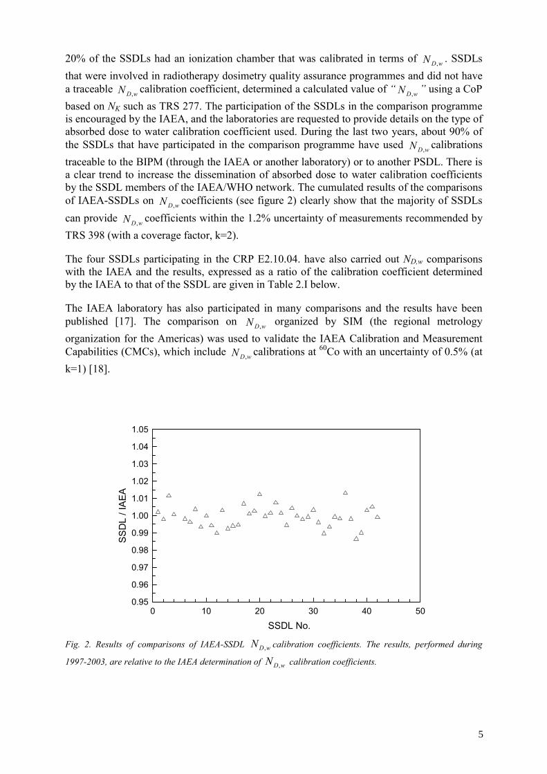
20% of the SSDLs had an ionization chamber that was calibrated in terms of wDN , . SSDLs that were involved in radiotherapy dosimetry quality assurance programmes and did not have a traceable wDN , calibration coefficient, determined a calculated value of “ wDN , ” using a CoP based on NK such as TRS 277. The participation of the SSDLs in the comparison programme is encouraged by the IAEA, and the laboratories are requested to provide details on the type of absorbed dose to water calibration coefficient used. During the last two years, about 90% of the SSDLs that have participated in the comparison programme have used wDN , calibrations traceable to the BIPM (through the IAEA or another laboratory) or to another PSDL. There is a clear trend to increase the dissemination of absorbed dose to water calibration coefficients by the SSDL members of the IAEA/WHO network. The cumulated results of the comparisons of IAEA-SSDLs on wDN , coefficients (see figure 2) clearly show that the majority of SSDLs can provide wDN , coefficients within the 1.2% uncertainty of measurements recommended by TRS 398 (with a coverage factor, k=2).
The four SSDLs participating in the CRP E2.10.04. have also carried out ND,w comparisons with the IAEA and the results, expressed as a ratio of the calibration coefficient determined by the IAEA to that of the SSDL are given in Table 2.I below.
The IAEA laboratory has also participated in many comparisons and the results have been published [17]. The comparison on wDN , organized by SIM (the regional metrology organization for the Americas) was used to validate the IAEA Calibration and Measurement Capabilities (CMCs), which include wDN , calibrations at 60Co with an uncertainty of 0.5% (at k=1) [18].
SSDL No.0 10 20 30 40 50
SS
DL
/ IA
EA
0.95
0.96
0.97
0.98
0.99
1.00
1.01
1.02
1.03
1.04
1.05
Fig. 2. Results of comparisons of IAEA-SSDL wDN , calibration coefficients. The results, performed during
1997-2003, are relative to the IAEA determination of wDN , calibration coefficients.
5
TABLE 2.I. RESULTS OF IAEA/SSDL COMPARISON OF ABSORBED DOSE TO WATER CALIBRATION COEFFICIENTS ( wDN , ). THE RESULTS ARE EXPRESSED AS A RATIO OF THE IAEA DETERMINED COEFFICIENT TO THAT STATED BY THE SSDL. THE UNCERTAINTY ON THE RATIO IS 0.4% [16].
SSDL IAEA wDN , /SSDL wDN ,
Algeria 0.997
Argentina 1.008
Norway 0.999
Thailand 0.993
2.1.2.2. Other radiation beams
Taking into account the status of development of standards of absorbed dose to water at PSDLs, it can be concluded that absorbed dose to water calibrations for 60Co radiation are widely available and thus, can be disseminated to SSDLs and to most end-users at hospitals. For high energy photons, the calibrations are available from some PSDLs; but due to unavailability of linear accelerators at SSDLs, it is unlikely that direct calibrations at QwDN ,, can be made available to end-users at hospitals without a PSDL providing QwDN ,, calibrations. A feasibility study was conducted by the participants of the CRP E2.10.04 to investigate the use of hospital based linear accelerators to cross calibrate hospital chambers and provide
QwDN ,, calibrations, based on experimental kQ values obtained from the Laboratoire National Henri Becquerel (LNHB). Further details on the calibration procedures used by the LNHB are given in Appendix B. Nine ionization chambers, from the SSDLs participating in the CRP, were calibrated at the LNHB. The type of chambers used in this study are given in Table 2.II. The chambers were sent from the SSDLs without electrometers; therefore, the calibrations were performed with the electrometer of the LNHB.
Figure 3 illustrates the variation of mean experimental values of kQ versus the beam quality index TPR20,10, for the chambers NE 2571, NE 2611A and PTW 30010 respectively. The uncertainty, at k=1, reported by the LNHB is 1.2%.
6
TABLE 2.II. ION CHAMBERS USED BY FIVE SSDLs TO INVESTIGATE THE FEASIBILITY OF USING HOSPITAL-BASED LINEAR ACCELERATORS TO PROVIDE
QwDN ,, CALIBRATIONS BASED ON EXPERIMENTAL kQ VALUES OBTAINED FROM THE LNHB.
From 02 April 2002 to 26 April 2002
October
17–24
2002
March
21–31
2003
IAEA SSDL Norway SSDL Argentina SSDL Algeria SSDL Thailand NE 2571 # 3204 NE 2571 #3016 NE 2571 # 2394 NE 2611A # 181 NE 2611A # 182
PTW W30010 # 55 NE 2611A # 153 NE 2611A # 133
NE 2611A # 145
0.94
0.95
0.96
0.97
0.98
0.99
1.00
1.01
0.66 0.68 0.7 0.72 0.74 0.76 0.78 0.8 0.82 0.84
Quality index TPR 20,10
k Q
NE 2571NE 2611APTW 30010
Fig. 3. Mean experimental kQ versus the beam quality index TPR20,10. The theoretical values are given by the continuous curves (Continuous: NE 2571, dots: NE 2611A and dashes: PTW30010). The error bars correspond to an uncertainty of 1.2 %.
For high-energy photons beams it is recognized that several PSDLs and all SSDLs do not have their own accelerators for the purpose of calibrating chambers in terms of absorbed dose to water. PSDLs or SSDLs that are not equipped with linear accelerators cannot realize or transfer absorbed dose to water standards for high-energy photons to end-users at hospitals. Consequently, most of the hospitals in countries, where such QwDN ,, calibrations are not available, will get only an absorbed dose to water calibration coefficient for an ionization chamber in a 60Co beam from the PSDL or SSDL and have to use the kQ values given in TRS 398. In exceptional situations, where hospitals are not properly equipped, SSDL staff may have to travel to hospitals and calibrate the hospital beams, using the SSDL equipment. In that case, all calibrations are done with an ionization chamber calibrated in terms of ND,w and the use of kQ values given in TRS 398 [1].
7
It should however be noted that for dosimetry consistency in a given country, SSDLs may well be requested by end-users to provide calculated QwDN ,, coefficients to hospitals based on 60Co calibration and kQ values taken from TRS 398. It should be emphasized that this is a calculated coefficient and does not ensure traceability to primary standards of high-energy photons. It is highly recommended that such service be provided only by SSDLs who have adequately trained staff in ionization chamber dosimetry. Furthermore, the SSDL’s calibration report to hospitals should clearly indicate all the steps followed to allow an easy check of the values provided to the hospital. The report should include the 60Co calibration coefficient with its stated uncertainty and calibration conditions (distance, depth in water, field size), the kQ values taken from TRS 398, the users’ beam qualities (TPR20,10) and the calculated
QwDN ,, coefficient with its overall uncertainty. For quality control purposes, it is also recommended that SSDLs calibrate all chambers in terms of air kerma. The use of the ratio ND,w/NK is a good indicator of consistency of standards [19].
For high energy electrons, only two PSDLs provide calibration coefficients for ionization chambers in terms of absorbed dose to water as a function of electron beam quality [19,20]; for low and medium energy X rays, only one PSDL provides such calibrations [12]. The experience gained by the SSDLs in the use of QwDN ,, for these beams is very limited and will be considered for publication in a future revision of this TECDOC.
2.2. Recommendation for the implementation of TRS 398 at SSDLs
2.2.1. General All SSDLs are encouraged to follow the steps shown below before providing routine calibration services to end-users. In view of the stringent requirements on accuracy of calibrations in radiotherapy dosimetry, it is especially important for SSDLs, that plan to implement TRS 398 by providing absorbed dose to water calibrations for 60Co beams, to follow this guidance.
(1) Training SSDL staff on ionization chamber dosimetry,
(2) Availability of adequate calibration room and calibration equipment,
(3) Calibration of a reference standard at a PSDL or IAEA,
(4) Development of absorbed dose to water standard at the laboratory,
(5) Hands-on preliminary stability check measurements (with check source), and absorbed dose to water rate measurements and recalibration of a field class instrument,
(6) Preparation of operating procedures for calibration measurements and quality control procedures,
(7) Assessment of uncertainty [22] (see Appendix A),
(8) Comparisons with the IAEA and/or Regional Metrology Organization (RMO) to validate the calibration capabilities,
(9) Preparation of CMCs and submission to the RMO (or IAEA for countries that are not signatories of the Convention of the Meter) for review,
(10) Arrange for a peer review of the laboratory quality system or seek formal accreditation by an appropriate body,
8
(11) Provide routine calibration services to hospitals3,
(12) Participate regularly in audits and comparisons and arrange for a periodic review of the laboratory quality system.
Efforts in PSDLs have concentrated on providing calibrations in terms of absorbed dose to water of ionization chambers in 60Co gamma-ray beams, and to a lesser extent in high-energy photon and electron beams [7, 23-25].
Depending on the standards laboratory, users may be provided with oQwDN ,, calibrations
according to different options. These options are described below4:
(a) The first approach is to provide users with a calibration coefficient at a reference beam quality Qo, usually 60Co. For additional qualities the calibration at the reference quality is supplied together with directly measured beam quality correction factors kQ,Qo for that particular chamber at specific beam qualities Q. Only laboratories having access to radiation sources and standards operating at different beam qualities can provide directly measured values of kQ,Qo for these qualities.
(b) An alternative approach, which is, in practical terms, identical to the one described above and differs only in the presentation of the data, is to provide a series of
QwDN ,, calibrations of the user ionization chamber at beam qualities Q. There is, however, an advantage in presenting the data by normalizing all calibration coefficients to a single calibration coefficient
oQwDN ,, together with directly measured values of kQ,Qo. Once directly measured values of kQ,Qo for a particular chamber have been obtained, it may not be necessary for the user to re-calibrate the chamber at all qualities Q, but only at the single reference quality Qo. Furthermore, this single reference quality calibration does not need to be performed at the same laboratory where the kQ,Qo values were measured (usually a PSDL).
(c) In the third approach users can be provided with a oQwDN ,, calibration coefficient for the
ionization chamber, most commonly at the reference quality 60Co, and theoretically derived beam quality correction factors kQ,Qo for that chamber type which must be applied for other beam qualities. This method ignores chamber-to-chamber variations in response with energy of a given chamber type. The calculated values of kQ,Qo rely on chamber specifications provided by manufacturers.
(d) A fourth approach, offered by some standards laboratories, is to provide a single measured
oQwDN ,, for a given chamber, obtained at a selected reference quality, together with generic 5 experimental values of kQ,Qo for that ionization chamber type. This option does not take into account possible chamber-to-chamber variations within a given chamber type. Furthermore, there are currently only limited experimental data on kQ,Qo for most commercial chambers. This approach has much in common with option (c) above and, if for a given chamber type, the theoretical values of kQ,Qo are verified
3 Some SSDLs start providing services after step 4. As a minimun, it is recommended to complete up to step 7 before providing the service. 4 Extracted from TRS 398 [1] 5 In the present context, generic stands for factors common to a specific ionization chamber type, supplied by a given manufacturer.
9
experimentally in a standards laboratory for a large sample of chambers, the theoretical values of kQ,Qo can be assumed to correspond to a mean value.
Based on these descriptions, the following recommendations are given for compliance with the recommendations of TRS 398 [1]:
(1) Approach (a), or its equivalent (b), are the preferred alternatives, although it is acknowledged that for beam qualities other than 60Co such possibilities are at present restricted to a few PSDLs.
(2) Approach (c) is recommended for those users who do not have access to kQ or kQ,Qo values directly measured at various beam qualities in a standards laboratory. The use of 60Co as the reference quality for determining ND,w is particularly appropriate for SSDLs, where the possibility of having an accelerator is remote. This approach is the most common practice today and favours the use of theoretical kQ factors (i.e. kQ,Qo with 60Co used as Qo).
(3) Approach (d) is an alternative option to (c) only when kQ or kQ,Qo values have been obtained by a standards laboratory from a large sample of ionization chambers and the standard deviation of chamber-to-chamber differences is small. This is usually the case for Secondary Standard quality chambers [19,20] such as those measured by the NPL (U.K.). Generic experimental kQ or kQ,Qo values not determined by a standards laboratory are not recommended.
(4) Low- and medium energy X ray dosimetry must be based on approaches (a) or (b) with the range of values of Q chosen to be as similar as possible to the qualities of the beams that will be used clinically.
(5) As long as there are restricted possibilities for establishing experimental QwDN ,, coefficients by standards laboratories in proton and heavy-ion beams the
theoretical approach (c) is the only recommendation to be used for such beams.
SSDLs have the responsibility to disseminate traceable standards to hospitals. In radiotherapy, mistakes in beam calibration [26] have happened because of a confusion of calibration coefficients. A typical mistake is confusion between ND,w and ND,air, (which was called ND in ICRU Report 35 [27] and TRS 277 [2]) leading to a 10-13% discrepancy in dosimetry. This type of confusion can potentially happen in countries where no specific dosimetry protocol is used and where physicists are not adequately trained. Consequently, it is important that a dosimetry protocol is formally adopted in a country. The adoption process is usually done by a professional society, when available. If not, health authorities or regulatory bodies can also recommend or require the use of a given protocol in a country. It is recommended that the adoption process also involve SSDLs that provide therapy level calibrations to ensure that the standards disseminated in the country are consistent with the recommended protocol.
For countries that are using air kerma based protocols and wish to make the transition to absorbed dose to water based protocols, it is equally important for them to adopt the new protocol following one of the mechanisms suggested above and also involve the SSDL. It is important for the SSDL and the end-users at hospitals to agree on a transition period during which both calibration coefficients (ND,w and NK) would be supplied to hospitals. During this transition period, the dose would be determined with ND,w coefficient and TRS 398 [1], and also with NK coefficient and TRS 277 [2]. If the latter provides a value that is consistent, taking into account the expected change, this would confirm the new approach.
10
2.2.2. Realization and dissemination of absorbed dose to water calibrations at 60Co gamma ray beam
The IAEA TRS 374 [28] covers procedures used for the calibration of instruments in radiotherapy, including the expression of measurement uncertainty. The present report deals with additional practical aspects related to the realization and dissemination of absorbed dose to water calibrations. The recommendations given below supplement those given in TRS 374 [28] and TRS 398 [1]. Efforts were made to minimize redundancy, but for the sake of clarity, it was not possible to avoid some repetition.
2.2.2.1. Equipment
2.2.2.1.1. Measuring assembly (electrometer)
Since many SSDLs do not have facilities to carry out charge calibrations, the measuring assembly is generally calibrated together with the ionization chamber and the calibration coefficient is given for the whole system (which consists of the ionization chamber and electrometer). In this case, there is no need for electrometer calibration. However, the ionization chamber should be used only with its electrometer. If one of the 2 components breaks down, they have to be calibrated again before they can be used. In contrast, when the chamber is given a separate calibration coefficient (i.e. Gy/C), the charge sensitivity of the measuring assembly must be checked indirectly as explained below.
Verification of electrometer calibration
The verification of the charge calibration by measurements can be done by the method given in TRS 374 [28]. Alternatively, it is possible to compare the sensitivity of a working electrometer with that of a reference (calibrated) electrometer in a radiation field. A suitable chamber is connected to the electrometer with a known charge sensitivity, the polarising voltage applied to the chamber. First both the electrometer and the chamber to be used should be tested for leakage. Then, the chamber is exposed to radiation at appropriate distance and the reading, taken during a fixed time and then corrected for ambient conditions. The total charge is calculated from the charge sensitivity and the output readings. The settings of the electrometer should be noted. The electrometer to be compared is similarly connected to the chamber, the polarising voltage applied and exposed to the same radiation field and readings taken are corrected for ambient conditions. From the standard charge and the corrected reading of the electrometer to be compared, the charge sensitivity or the correction factor can be checked. A correction factor, expressed as a ratio of corrected charge of the reference electrometer to corrected charge of the working electrometer, can be determined. The displayed units may be in volts, coulombs or any displayed units. The stability of the measuring assembly shall also be tested in both polarities for the chamber. After the polarising voltage is reversed, about 20 minutes should be allowed for the system to stabilise before taking the measurements.
Stabilization time for ion chamber and measuring assembly
The ionization chamber and the measuring assembly require a certain amount of time after switching on the instruments and before measurements can be started. This effect has been studied for 5 different ionization chambers in a 60Co beam. Fig. 4 shows the variation of the chamber response, expressed as a percentage of maximum ionization, as a function of time after switching on the 60Co unit, for measurements done in water. The stabilization time of the electrometer is excluded from the data of Fig. 4. It appears from this figure that the time
11
required to reach the maximum response is chamber dependent. Fig. 5 shows an example of a stabilization time needed by a Keithley 6517 electrometer. As illustrated by these two figures, it takes about 30 min for the readings of the measuring assembly and ion chamber to reach an acceptable level of stabilization.
0.994
0.995
0.996
0.997
0.998
0.999
1.000
1.001
0 5 10 15 20
Time (min)
Q/Q
max
Fig. 4. Stabilization time for ionization chambers alone. The symbols used represent different type of ionization chambers (empty and filled circles: WDIC-70, empty squares: NACP, filled triangles: PTW-30001 and filled squares: NE-2611A).
0.995
0.997
0.999
1.001
1.003
1.005
0 10 20 30 40 50 60
Time (min)
Q/Q
max
Fig. 5. Stabilization time for a Keithley 6517 and a PTW 23333 ionization chamber. A full stabilization is achieved after about 30 min.
2.2.2.1.2. Phantom and waterproof sleeves
• Water phantom: full scatter water phantoms are recommended with the minimum size of 30 cm x 30 cm x 30 cm. The phantom should extend at least 5 cm beyond all four sides for the largest field size used at the depth of measurement. There should be a margin of at least 5 g/cm2 beyond the maximum depth of measurement. If the beam enters through the plastic wall of the water phantom, the window thickness should be between 0.2 to 0.5 cm. The dimensions of the window should be 10 cm by 10 cm. The water equivalent thickness
12
(in g/cm2) of the phantom window should be taken into account when evaluating the depth at which the chamber is to be positioned; the thickness is calculated as the product twin ρpl, where ρpl is the mass density of the plastic (in g/cm3). For the commonly used plastics PMMA and clear polystyrene, the nominal values ρPMMA =1.19 g/cm3 and ρpolystyrene =1.06 g/cm3 may be used for the calculation of the water equivalent thickness of the phantom window. For non-waterproof chambers, a waterproofing sleeve should be used, made of PMMA and preferably not thicker than 1.00 mm. The air gap between the chamber wall and the waterproofing sleeve should be sufficient (0.1-0.3 mm) to allow the air pressure in the chamber to equilibrate. It is recommended that both waterproof and non-waterproof chambers, be calibrated with a PMMA waterproof sleeve. Obviously, it is possible to calibrate a water proof chamber without a PMMA sleeve; however, experience has shown the positioning of cylindrical chambers without a rigid sleeve is not easy. Furthermore some SSDLs are equipped with a so-called “IAEA phantom” that cannot be used to calibrate waterproof chambers alone.
• Pressure measurements: at SSDLs, it is a good practice to use two barometers for pressure measurements, a reference barometer and a working barometer. Preferably, the reference barometer should have a calibration traceable to a PSDL and be used to “cross-calibrate” the working barometer. It is realized that this may not be possible in countries where pressure calibrations are not available and that many countries lack resources to pay for a calibration abroad. Under these special circumstances, it is recommended to send one of the barometers to the PSDL/IAEA calibration laboratory and ask for verification. The verification is done by taking repeated measurements over many days of the SSDL’s barometer and comparing them with those of the PSDL’s or IAEA’s reference barometer. An example of such comparison is shown in figure 6.
Fig. 6. Example of comparison of a reference barometer with a working barometer conducted at the IAEA laboratory. Continuous measurements were made with the reference barometer. Correction factors for the working barometer can be deducted from the measurements.
• Thermal stabilization: the water phantom should be filled with water previously stored in a tank located in the calibration room. Before the beginning of the measurements, the chamber with waterproof sleeve should be left inside the water phantom for about half an hour.
wor
king
bar
omet
er /
refe
renc
e ba
rom
eter
0.990
0.995
1.000
1.005
1.010
Working barometer Reference barometer
Time (24 hours)
13
• Temperature measurements: following the same principle as outlined above for pressure measurements, the SSDL should also use two thermometers (mercury or thermocouples) for temperature measurements. Figure 7 shows an example of cross calibration, at the IAEA laboratory, of working thermometers against a reference thermometer calibrated at a PSDL. The temperature should be measured with a probe placed inside the water phantom. Fig. 8 shows the difference in temperature readings between air and water. The figure also shows that there is no significant difference between different ways of temperature measurements if the probe is immersed in water: inside a dummy cavity ion chamber (obtained by removing the central electrode of a broken ion chamber), inside a water proof sleeve and simple immersion. It can be seen that after 10 minutes, the temperatures in water and in the sleeve stabilize and reach the same value whereas, in air, the fluctuations are more important and the mean value is about 1.5 °C higher than the temperature in the chamber cavity. For in water measurements, the temperature probe should be placed on the backside of the phantom and outside the beam, to avoid any additional scatter.
Fig. 7. Example of cross calibration of thermometer at the IAEA laboratory. The figure shows typical measurements of temperature probe readouts during one day. The readouts of the probes to be cross calibrated are compared to those of the reference thermometer (dotted line). Note that the fluctuations of temperature readings during the normal laboratory working hours (8:00-17:00) are within 1°C. The data shown in this graph represent a typical set of measurements recorded automatically during five working days.
• Window deformation: for phantoms with larger window area, care should be taken of the window deformation due to the water pressure. This deformation can be monitored with a positioning system, such as a mechanical pointer.
• For phantoms with an open window (vertical irradiation), one should accurately check the chamber depth and be aware of water level changing with time (evaporation)
• The water should be removed from the phantom after the calibration is finished.
tem
pera
ture
[°C
]
20.0
20.5
21.0
21.5
22.0
Time (24 hours)
Reference thermometer
14
17.0
17.5
18.0
18.5
19.0
19.5
20.0
0 5 10 15 20 25 30
Time (min)
Tem
pera
ture
(°C
)Probe in w ater
Probe in dummy cavity
Probe in sleeve
Fig. 8. Temperature variations in air and water. The figure shows no significant difference between different ways of temperature measurements if the probe is immersed in water, placed inside a dummy cavity ion chamber or inside a waterproof sleeve.
2.2.2.1.3. Positioning system
• The absorbed dose to water needs to be measured with a chamber in a water phantom. The source-phantom surface distance and the depth of the chamber axis must be reproducible and known. A mechanism, such as a rigid rod or a combination of a laser beam and a telescope alignment device, is needed to accurately align the chambers at a distance. For the “IAEA water phantom” with fixed sleeve positions, a test for the deformation of front window should be carried out regularly. For phantoms with adjustable sleeve depths, a small distance rod or a counter mechanism is needed to ensure a reproducible depth in water (see figure 9).
Fig. 9. Positioning system used at IAEA dosimetry laboratory for absorbed dose to water calibrations. It consists of a water phantom and a translation stage, which is used to move the chamber precisely along the direction indicated by the arrow above the water phantom.
10 c
m
10
cm×
100 cm
5g/cm²
15
2.2.2.1.4. Quality control of calibrations
As recommended in TRS 374 [28], it is a good practice to develop and implement a quality control programme for SSDLs. Recommendations are given in that publication. Further details that relate specifically to absorbed dose to water calibrations are given in this section.
• 60Co head (irradiator) used for calibration: the machine should be commissioned before it is used for calibration purposes. The commissioning process should be repeated when the source is exchanged or after major repair (such as a change of the collimators). Figure 10 shows an example of a change in the absorbed dose to water rate following a change of the collimators of the IAEA’s 60Co machine. The commissioning should include checks of all the safety features, geometrical and mechanical checks [29] for the head, cross beam profiles, verification of depth dose curve and comparison with data given by ref. [30], and finally the determination of the absorbed dose to water rate in reference conditions.
Fig. 10. Change in the absorbed dose to water rate following a change of the collimators of a 60Co machine at the IAEA laboratory. A change of almost 4% in the absorbed dose to water rate was identified.
• Reference and working standards: SSDLs should have a reference standard and a working standard to be used for the calibration in terms of absorbed dose to water. Both standards can be of the same type. The reference standard should be calibrated periodically at a PSDL/IAEA laboratory and used to cross calibrate the working instruments. It is recommended that the recalibration periodicity not exceed five years6. The quality control programme to ensure stability of the standards include: stability of output measurements (absorbed dose to water rate) determined periodically with the reference standard, periodical recalibration of the working standard (see example shown in Fig. 11), check source measurements, external feedback capacitor checks, and voltmeter stability (if used at the SSDL) and verification of electrometer readings.
• Quality control: in addition to the quality control programme recommended in TRS 374 [28], it is suggested that before and after calibrating an ion chamber in terms of absorbed dose to water in a 60Co beam, a calibration in air kerma is also done for quality control
6 For hospitals, it is recommended in TRS 398 [1] that the reference ionization chamber be calibrated at a PSDL or SSDL at intervals not exceeding 2 to 3 years. For SSDLs, and provided that a quality control programme is implemented to ensure the stability of the standards, a periodicity not exceeding 5 years is recommended in the SSDL Charter [4]
Date (Sept. 2001-May 2002)
D w
(rel
. uni
ts)
1.00
1.01
1.02
1.03
1.04
1.05
Before change of collimator
After change of collimator
16
purposes (even if it was not requested by the customer). It is interesting to get an idea on the variability of the ratio of KwD NN , for particular chamber types. If the variability of the ratio is small, it can provide an additional quality control tool to check the consistency of the calibrations at SSDLs. By comparing the ratio of KwD NN , for one particular ion chamber to the mean value for that type of chamber, an indication on the peculiarities of this specific ion chamber can be deduced. If this ratio is different by more than 0.5 % from the mean value, the user should be informed that the ion chamber is not “typical” and that extra care should be taken when using the kQ values.
0.997
0.998
0.999
1.000
1.001
1.002
1.003
1.004
Nov-01 May-02 Dec-02 Jul-03 Jan-04 Aug-04Date
Abso
rbde
d do
se to
wat
er ra
te
mea
sure
men
ts (n
orm
alzi
ed to
mea
n va
lue)
Fig. 11. Absorbed dose to water rate measurements in a 60Co beam at the IAEA laboratory during November 2001-September 2004. The spread of the measurements is 0.08%.
2.2.2.1.5. Uncertainty budget achievable at SSDLs
As recommended by ISO [22], and IAEA [1,28] that all calibration certificates shall include an estimate of the measurement uncertainty achievable at the SSDL. The estimation has to be done following ISO guidelines. Typically, the uncertainty (at k=1) achievable at SSDLs for absorbed dose to water calibrations lies in the range of 0.5%-1%, depending on the uncertainty of the calibration of the standard and also on the calibration procedure and equipment used at the SSDL. A detailed uncertainty analysis is given in Appendix A. Readers are encouraged to study the example and work out their own analysis, taking into account their equipment and procedures used.
2.2.2.1.6. Reporting of results to hospitals 60Co gamma ray beam
The calibration coefficient of the user instrument together with its uncertainty should be reported to the end-user. The coverage factor should be explicitly mentioned in the calibration certificate. For hospitals, it is highly recommended to calibrate ion chamber together with its electrometer and request the hospitals to send a waterproof sleeve together with the ion chamber to be calibrated. It is a good practice to attach to the calibration certificate a
17
document describing the calibration procedure followed by the SSDL. As a minimum, the following information should also be included in the calibration certificate: name and address of end-user, data on the user’s chamber and electrometer (type and serial number), thickness and material of water proof sleeve, electrometer settings, calibration date, set-up (field, distance), reference ambient conditions (T,P), calibration coefficients and related uncertainty (the coverage factor should be specified). Additional information on calibration periodicity, reference to national regulation or accreditation of the SSDL and source of traceability should be provided on the certificate.
Other beam qualities
It is unlikely that SSDLs will be able to provide traceable absorbed dose to water calibrations at beam qualities other than at 60Co gamma radiation. Generally SSDLs are expected to provide only traceable calibrations to end-users in hospitals (ND,w and NK for 60Co and NK for X rays). The end-user is then expected to determine absorbed dose to water rate in the hospital beam, using an appropriate CoP, such as TRS 398 [1]. For the sake of consistency and standardization of dosimetry at the national level, the SSDL and the medical physics community (e.g. through a professional society) may mutually agree to extend the scope of the SSDL work to include additional services to other radiation beams used in the country (e.g. X rays, high energy photons and electrons). If such agreement is reached and if the SSDL staff is adequately trained in ionization chamber dosimetry applicable to the clinic, the SSDL may derive “calculated calibration coefficients” using one of the accepted Codes of Practice and disseminate them to all end-users in the country. This provision is included in TRS 398 [1] and was specifically recommended for X rays where only one PSDL can provide absorbed dose to water calibrations.
For high-energy photons beams and taking into account the results of measurements obtained by the CRP participants (see Fig. 3), it is not recommended for SSDLs to cross calibrate users’ chambers using hospitals’ linear accelerators and SSDL chambers with experimentally determined kQ values. The overall uncertainty achievable by SSDLs for this type of cross calibration in a non-laboratory environment is very close to the uncertainty achievable if kQ from TRS 398 [1] values are used. Typically, the overall uncertainty on the determination of absorbed dose to water rate in high energy photon beams achieved by SSDLs in the pilot study was about 1.2% when experimentally determined kQ values are used.
18
3. OVERVIEW OF FORMULATION OF VARIOUS INTERNATIONAL AND NATIONAL CODES OF PRACTICE
3.1. General A summary of the formulation in the various international Codes of Practice and national protocols will be presented in order to establish a parallelism among them. The original notations used by the various CoPs and protocols for various interaction coefficients, influence quantities and perturbation correction factors will be retained in the discussion of the present section. However, in the subsequent sections the notations given in the TRS 398 [1], TRS 277 [2] and TRS 381 [3] will mostly be used except in cases where clarification is needed. For details on the various quantities, notations and correction factors, readers are invited to consult the original references of the IAEA TRS 398 [1], TRS 277 2nd edition [2], TRS 381 [3], TRS 277 [32], AAPM TG-21 [31] and TG-51 [33], German DIN 6800-2 [34], ICRU-59 [35] and CoP from DKFZ [36].
3.2. High-energy photon and electron beams
3.2.1. IAEA TRS 277 NK-based protocols determine the absorbed dose to water at a reference depth in a phantom in a two-step process. In the first step a chamber factor in terms of the absorbed dose to the cavity air, ND, is derived:
mattKD kkg(NN )1 −= (1) where the meaning of the factors g, katt and km and their values for a large set of ionization chambers were given in TRS 277 [32]. In the second step, the absorbed dose to water, Dw,Q, at a point in a phantom where the effective point of measurement of the chamber is positioned, is obtained from the dose to the cavity air using the Bragg-Gray principle,
w,Q eff Q eff D w,air Q QD (P ) M (P )N (s ) p= (2)
where MQ is the dosimeter reading at the beam quality Q corrected for influence quantities (pressure, temperature, recombination and polarity); sw,air is the stopping power ratio, water to air; pQ is the perturbation factor of the ionization chamber for in-phantom measurements at the beam quality Q; and Peff is the effective point of measurement of the chamber, shifted from the chamber centre towards the radiation source. It is emphasized that with Eq. (2) the absorbed dose to water is determined at the point where Peff is situated. Note that in TRS 277, where the beam quality Q was denoted by “u” (the user beam quality), the concept of perturbation factor was simplified; for photon and electron beams, pu was identified, respectively, with the wall and electron fluence perturbation factors denoted by pwall and pcav in subsequent Codes of Practice. An additional global perturbation factor pcel-gbl was introduced to account for the effect of the metallic central electrode in many cylindrical ionization chambers; this was denoted by pcel in TRS 277. The complete perturbation factor pQ in TRS 277 could thus be written as
( )QgblcelwallcavQ pppp −= (3)
19
where for electron beams pwall = 1 and for photons pcav =1. TRS 277 did not provide details on the calibration and use of plane-parallel chambers. For these chambers, all perturbation factors were assumed to be unity.
The second edition of TRS 277 published in 1997 [2] introduced numerical changes in the shift of the effective point of measurement of cylindrical ionization chambers, harmonizing the value for all photon beams to 0.6 rcyl, where rcyl is the radius of the air cavity of a cylindrical chamber. Updated values were recommended for the global perturbation factor pcel-gbl; these values were half of those given in 1987 [32]. This introduced noticeable changes in the dose determination, mainly for electron beams, as the factor entered into the cross-calibration procedure of plane-parallel chambers.
3.2.2. IAEA TRS 381 The protocol TRS 381 [3] was mainly developed to complement TRS 277 in the field of electron beam dosimetry with plane-parallel chambers, taking into account the updated values mentioned above. However, its purpose was also to update the formalism of TRS 277 so that the trends for chamber calibrations in terms of absorbed dose to water, ND,w, included in TRS 381, would be consistent with the existing NK procedures. Eq. (1) for the chamber factor was replaced by:
celmattKairD kkkgNN )1(, −= (4)
where the subscript “air” was included in ND to specify without ambiguity that it refers to the absorbed dose to the air of the chamber cavity. The factor kcel takes into account the non-air equivalence of the central electrode of a cylindrical ionization chamber only during the chamber calibration in terms of air kerma at 60Co. TRS 277 did not include explicitly kcel. Instead, it had been included in the global factor pcel-gbl to account for the combined effect of the central electrode of a cylindrical chamber, both during the calibration of the chamber in air in 60Co and during subsequent measurements in photon and electron beams in a phantom. The numerical value of ND,air for cylindrical chambers with a 1 mm diameter aluminium central electrode (NE 2571) is therefore 1.006 greater than ND of TRS 277, even if the absorbed dose to water at 60Co is the same due to cancellation of the two factors correcting for electrode effects (see below). The new pcel corresponds only to in-phantom measurements in photon and electron beams, and as it will be shown below, it enters into the calculation of the so-called kQ factors of the ND,w formulation, whereas kcel does not.
Based also on the needs for the ND,w formulation, TRS 381 allowed the use of a chamber displacement perturbation factor, pdis, to account for the effect of replacing a volume of water with the cavity of a cylindrical ionization chamber, as an alternative to the use of the effective point of measurement of the chamber. In this case the reference point of the detector is taken to be at the cylindrical chamber centre. Eq.(2) thus becomes:
(ch centre) (ch centre)w,Q Q D,air w,air Q QD M N (s ) p= (5)
and Eq. (3) for the perturbation factor is modified to:
QcelwalldiscavQ ppppp )(= (6)
20
With regard to specific recommendations for the calibration and use of plane-parallel chambers, TRS 381 provides details for cross-calibration procedures in high-energy electron beams as well as in 60Co. Simpler procedures than in TRS 277 are included for the determination of energy-related parameters, together with new stopping-power ratios, procedures for measurements in plastic phantoms, etc. Most important, perturbation factors are provided for a variety of plane-parallel ionization chambers. This introduces considerable changes in electron beam dosimetry notably for chambers without an appropriate guard zone (like the Markus, for example). As already indicated, TRS 381 included detailed procedures for the use of the absorbed dose to water formalism, serving as a bridge between the NK- and ND,w-based formalisms.
3.2.3. IAEA TRS 398
In TRS 398 [1] the absorbed dose to water at the reference depth zref in water for a reference beam of quality Qo and in the absence of the chamber is given by
ooo QwDQQw NMD ,,, = (7)
where oQM is the reading of the dosimeter under the reference conditions used in the
standards laboratory and oQwDN ,, is the calibration coefficient in terms of absorbed dose to
water of the dosimeter provided by the standards laboratory at the reference beam quality oQ . When a dosimeter is used in a beam of the same quality as that used at its calibration, oQ , the absorbed dose to water is simply given by Eq. (7), where the dosimeter reading
oQM is corrected to the references values of temperature and pressure for which the calibration coefficient is valid, as well as by other influence quantities like polarity and recombination effects. When a dosimeter is used in a beam of quality Q different from that used at its calibration, oQ , the absorbed dose to water is given by
oo QQQwDQQw kNMD ,,,, = (8)
where the chamber specific beam quality correction factor kQ,Qo corrects for the effects of the difference between the reference beam quality oQ and the actual user quality Q. Depending on the standards laboratory, users may be provided with different types of
oQwDN ,, calibrations. The options available, together with specific recommendations in each case, are summarized in the Code of Practice.
The beam quality correction factor kQ,Qo is defined as the ratio, at the qualities Q and oQ , of the calibration coefficients in terms of absorbed dose to water of the dosimeter
oo
QwD
QwDQQ N
Nk
,,
,,, = (9)
The most common reference quality oQ used for the calibration of ionization chambers is 60Co gamma radiation, in which case the symbol kQ is used without oQ . Ideally, the beam quality correction factor should be measured directly for each chamber at the same quality as the user clinical beam. However, this is not achievable in most standards laboratories. For users
21
without access to specific ND,w,Q calibrations obtained experimentally, TRS 398 provides kQ factors calculated theoretically using the Bragg-Gray theory:
( )( )
Coceldiscavwall
Qceldiscavwall
Coairw
QairwQ pppp
pppps
sk
6060 )()(
,
,= (10)
which is based on the assumed constancy of the mean energy expended in air per ion pair formed, Wair. The expression for kQ includes therefore ratios, at the qualities Q and 60Co, of the water/air stopping-power ratios, sw,air, and of the chamber dependent perturbation correction factors pQ that take into account the departures from an ideal Bragg-Gray detector. It is important to notice that for the few chambers where experimentally derived data are available, measured and calculated kQ factors generally agree within the uncertainties estimated for each method [37].
For reference dosimetry in electron beams TRS 398 recommends the cross calibration of a plane-parallel chamber against a reference (ND,w calibrated) chamber in a high-energy electron beam of quality Qcross to obtain a calibration coefficient for the plane parallel chamber at this quality, ND,w,Qcross. When this chamber is subsequently used for reference dosimetry in an electron beam of quality Q, Eq. (8) transforms into
crosscross QQQwDQQw kNMD ,,,, = (11)
where crossQQk , is given by
int
int
,
,,
QQ
QQQQ
crosscross k
kk = (12)
The protocol provides values of kQ,Qint for different qualities Q together with recommendations for evaluating ND,w,Qcross. It should be noticed that the intermediate quality, Qint, has no relevance for the user. It is only an auxiliary variable introduced to simplify the data tables, and the user only has to consider his/her own clinical beam quality Q.
TRS 398 recommended using water as the reference medium for the determination of absorbed dose in high-energy photon and electron beams. Solid phantoms in the form of slabs may be used under certain circumstances for low energy electron beams for beam qualities R50 < 4 g/cm2 (E0 < 10 MeV) and their use is permitted when no waterproof chamber is available or when accurate positioning in water is not possible.
To determine the absorbed dose to water at zref in water using a plastic phantom, the reference point of the chamber must be positioned at the scaled reference depth zref,pl in plastic. zref,pl ,expressed in g/cm2 ,is obtained from zref using the equation
cz
zpl
refplref =, (13)
where cpl is a depth scaling factor. The cpl is the ratio of the average depth of electron penetration in water and in plastic, where these depths are expressed in g/cm2:
w wpl
pl pl
zc z
ρρ
= (14)
22
In addition to depth scaling, the dosimeter reading MQ,pl at the reference depth in plastic zref,pl must be converted to the equivalent reading MQ at the reference depth in water zref using the relation:
plplrefplQrefQ hzM zM )()( ,,= (15)
where hpl is the fluence scaling factor and is generally energy dependent.
3.2.4. AAPM TG-51 The TG-51 protocol [33] provides a formulation that is similar to Eqs. (7) and (8) and, for the recommended calibration of the chamber at the quality of 60Co gamma rays, the absorbed dose to water at the reference depth in water in a beam of quality Q is given by
CowDQ
Qw NMkD
60,= (16)
where Qk converts the absorbed dose to water calibration coefficient for the 60Co beam, CowDN
60
, , into the calibration coefficient for an arbitrary beam of quality Q . For electron beams,
Qk is written as a product of three factors, i.e. ecalRQ
grQ kkPk 50′= , where the photon electron conversion factor ecalk converts the absorbed dose to water calibration coefficient of an
ionization chamber in a 60Co beam, CowDN
60
, , into an electron beam absorbed dose calibration
coefficient ecalQwDN , for a selected beam quality ecalQ and
50Rk ′ is needed to convert
ecalQwDN , into Q
wDN , for any beam quality Q. The cross-calibration technique refers only to a reference chamber calibrated in 60Co, which
determines the product [ ]ppCowDecal Nk
60
, . This product is then used in the equation
[ ]ppCowDecalR
Qgr
Qw NkkMPD 60
,50′= (17)
for the determination of absorbed dose to water at all electron beam energies using the cross-calibrated plane-parallel chamber.
3.2.5. German DIN 6800-2 The German protocol for dosimetry DIN 6800-2 [34] is based upon the use of air-filled ionization chambers calibrated in terms of absorbed dose to water in a 60Co gamma ray beam. The calibration coefficient applies for a set of reference conditions such as geometrical arrangement (see DIN 6800-2, Table 1), material and dimension of the phantom, or air density. All factors, which may lead to a deviation from the reference conditions, are called influence quantities and corrections must be implemented for them. The main correction factors are those for the air density kρ, for the effect of ion recombination, ks, for the polarity effect, kp, and for the displacement effect at a 60Co-gamma ray beam calibration, kr. The departure from 60Co gamma radiation is also treated as an influence quantity that needs the correction factor kQ and kE for high-energy photons and electrons, respectively. Measurements
23
at other radiation qualities require modified geometrical reference conditions that are also included in the mentioned Table 1.
According to DIN 6800-2, the general expression for the absorbed dose to water, ( )effw PD , in a field of radiation is given by:
MNk)P(D effw = (18)
where k is the product of the correction factors of all influence quantities including the beam quality, N is the calibration coefficient, and M is the reading of the chamber placed at reference depth. The measurements always refer to an effective point of measurement in the phantom, Peff, which for a cylindrical chamber is shifted from the chamber axis towards the radiation source by approximately 0.5 rcyl. This procedure, however, does not apply to 60Co gamma radiation during measurement and calibration. Because of the different treatment of this displacement effect during the calibration in 60Co and a measurement in a beam of high-energy photons and electrons, the calibration coefficient has always to be applied in combination with a correction factor, kr, which takes into account the displacement effect in 60Co gamma radiation during the calibration. A displacement correction factor is not included in the calculation of kQ and kE. The beam quality correction factors kQ as well as kE are considered to consist of a product of two factors:
QQQ ''k'kk ⋅= or EEE ''k'kk ⋅= (19)
The first factor is the quotient of Spencer-Attix water/air stopping-power ratios, sw,air at the beam qualities Q (or E) and 60Co:
( )( ) Coairw
QairwQ s
sk
60,
,' = (20)
The second one is a chamber specific factor consisting of the quotient of overall perturbation correction factors pQ (or pE ) and
Cop60 at the beam qualities Q (or E) and 60Co. These factors
include all departures from the ideal Bragg-Gray detector conditions:
Co
QQ p
pk
60'' = (21)
For the measurement of absorbed dose in high-energy photons, DIN 6800-2 only allows such cylindrical chambers for which an approval is given by PTB. The calculated kQ values are given as a function of the beam quality index which is defined as the tissue phantom ratio TPR20,10. For a very limited number of chambers, numerical values for kQ are given. In all other cases, kQ has to be calculated based on tables given in DIN 6800-2 for k'Q and k''Q. In addition, an equation for pQ is given, which, however, only includes the wall perturbation effect.
For electron beams, the beam quality indices are given by the mean energy at phantom surface 0E , a so-called virtual initial energy, 'E0 and the practical range pR . 'E0 is needed to correctly calculate the stopping power ratios that are needed for the calculations of the beam quality correction factor k'E and are obtained from 0E and pR through the use of an analytical expression. A formula is given to determine water/air stopping-power ratios, sw,air, at any
24
depth and at any set of beam quality specifying parameters. Hence, the determination of absorbed dose is not restricted to be performed at a specific reference depth condition. As a consequence, however, the steps to be done are more complex compared to that in TRS 398 [1]. For example, kE always must be derived as the product from its two constituting factors. Perturbation correction factors are derived differently according to the following three cases: (a) for plane-parallel chambers pE is equal to one, (b) for cylindrical chambers, pE is given as a function of the mean electron energy at measuring depth, (c) for plane-parallel chambers pCo must be measured by a comparison against a calibrated cylindrical chamber. Therefore, although not explicitly expressed as a cross calibration, this same cross calibration procedure as recommended in TRS 398 generally applies to the use plane-parallel chambers.
3.3. Protocols for low-energy kilovoltage X ray beams
3.3.1. Formalism based on NK calibrations: IAEA TRS 277 The dosimetry of low energy X rays has traditionally been based on measurements in air of exposure or air kerma. A calibration coefficient
0,QKN is then available. No extra phantom is used for the measurement but the ionization chamber may be embedded in some material, which then has to be regarded as part of the chamber. 7 The absorbed dose to water at the phantom surface in the absence of the ionization chamber, when the reference point of the chamber is positioned in accordance to the reference conditions described in section 7.4.2 (Table 7.III.), is given in IAEA TRS 277 [2] by:
ooooo Qairfree
Qw,airenK,Qairfree
QQw p])/[( BNMD ρµ=, (22)
The air kerma calibration coefficient
0,QKN measured free in air includes the effect of any
material in which the ion chamber is embedded, B is a backscatter factor, ( )[ ]freeair
Qairwen0
,/ ρµ is
the ratio of the mean mass energy absorption coefficients in free air, and Qop is assumed to be unity for the plane-parallel chambers used. The formalism used in other protocols, IPEMB [38] NCS [39] and DIN [40] can be described by the same equation as used in TRS 277 [2] even though the symbols may differ. In air kerma-based protocols, such as TRS 277 and IPEMB, the beam quality is characterized by the first half value layer (HVL). On the other hand, for DIN and NCS, the radiation quality is characterized by the first half value thickness in aluminium and the tube voltage. As an alternative to the use of NK based calibrations and in-air measurements, TRS 277 [2] recommended a new formalism and procedures that is based on the use of an ionization chamber calibrated in terms of absorbed dose to water for the calibration of low energy kilovoltage X ray beams. This formalism has also been recommended in TRS 398 [1], which is given below. The reference conditions for determination of absorbed dose to water recommended in TRS 398 are practically the same as those given in TRS 277.
7 This is a very important aspect of low-energy X rays dosimetry because plane-parallel chambers can be
calibrated with or without a PMMA mini-phantom by different laboratories. Calibrations without mini-phantom seem to be the most common. Especially at low energies, the NK calibration coefficients with or without a mini-phantom might be different.
25
3.3.2. Formalism based on wDN , calibrations: IAEA TRS 398
The absorbed dose to water at the phantom surface, in a low energy X ray beam of quality Q and in the absence of the chamber, is given by:
Dw,Q = M Q ND,w,Qo kQ,Qo (23)
where QM is the reading of the dosimeter with the reference point of the chamber positioned at refz in accordance with the reference conditions given in Table 7. IV. and corrected for the influence quantities temperature and pressure and electrometer calibration; , oD,w QN is the calibration coefficient in terms of absorbed dose to water at the reference quality oQ and , oQ Qk
is a chamber specific the beam quality factor, which corrects for differences between the reference beam quality oQ and the actual beam quality used, Q. Measurements must always be made in a phantom. The calibration data for a chamber should ideally be presented as a single calibration coefficient , oD,w QN determined in a reference beam quality oQ and one or more measured factors , oQ Qk corresponding to the other calibration quantities Q. However, if the calibration data are in the form of a set of calibration coefficients ,D,w QN then one of the qualities should be chosen as the reference beam quality oQ . The corresponding calibration coefficient becomes , oD,w QN and the other calibration coefficients ,D,w QN are expressed in terms of , oQ Qk
using the relation:
0
, ,,
, ,o
D w QQ Q
D w Q
Nk
N= (24)
If the quality of the user beam does not match any of the calibration qualities, the value for , oQ Qk to be used in equation (23) should be interpolated (for example using the formula given
in worksheet 8.8 of TRS 398).
3.4. Protocols for medium-energy kilovoltage X ray beams
3.4.1. Formalism based on NK calibrations
3.4.1.1. IAEA TRS 277
The absorbed dose to water at 5 cm depth in water, in a medium energy kilovoltage X ray beam of quality Q and in the absence of the chamber, is given in ref. [2] by
uairw
enuKuw pkNMD
,
= ρµ (25)
where Mu is the reading of the dosimeter with the centre of the chamber positioned at 5 cm depth under reference conditions and corrected for influence quantities (pressure, temperature, recombination and polarity), pu is the perturbation factor of the ionization chamber for in-phantom measurements at the beam quality Q. Note that in TRS 277, the beam quality Q was denoted by “u” (the user beam quality).
26
3.4.1.2. IPEMB
The recommended reference depth for medium-energy X ray beam is 2 cm in water phantom [38]. The absorbed dose to water, Dw, at this reference depth under reference conditions is given by
φρ
µ
,2,2,
=
=
=Zairw
enchKZw kMND (26)
where Dw,z=2 is the dose to water in Gray at the position of the chamber centre at the depth z = 2 cm when the chamber is replaced by water. M is the dosimeter reading corrected for influence quantities (pressure, temperature, recombination and polarity), NK is the chamber calibration factor in Gy per scale reading to convert the instrument reading at the beam quality concerned to air kerma free in air at the reference point of the chamber with the chamber
assembly replaced by air, ( )[ ]φ
ρµ,2, =Zairwen is the ratio of the mean mass-energy absorption
coefficient, water to air, averaged over the photon spectrum at 2 cm depth of water and field diameter φ, and kch is a factor which accounts for the change in the response of ionization chamber between calibration in air and measurement in a phantom.
3.4.2. Formalism based on ND,w calibrations: IAEA TRS 398 The absorbed dose to water at the reference depth zref in water, in a medium-energy X ray beam of quality Q and in the absence of the chamber, is given by
Dw,Q = M Q ND,w,Qo kQ,Qo
(27) where QM is the reading of the dosimeter with the reference point of the chamber positioned at refz in accordance with the reference conditions given in Table 8. II and corrected for the influence quantities temperature and pressure, polarity and electrometer calibration; , oD,w QN is the calibration coefficient in terms of absorbed dose to water at the reference quality
oQ and , oQ Qk is a chamber specific beam quality correction factor, which corrects for differences between the reference beam quality oQ and the actual beam quality used, Q. Values of , oQ Qk must be obtained directly from measurements. Generic values, measured for a particular chamber type, should not be used because of large chamber-to-chamber variations in kQ,Qo with HVL. The calibration data for a chamber should ideally be presented as a single calibration coefficient , oD,w QN determined in a reference beam quality oQ and one or more measured factors , oQ Qk corresponding to the other calibration quantities Q. However, if the calibration data are in the form of a set of calibration coefficients ,D,w QN then one of the qualities should be chosen as the reference beam quality oQ . The corresponding calibration coefficient becomes , oD,w QN and the other calibration coefficients ,D,w QN are expressed in terms of , oQ Qk
using the relation:
0
, ,,
, ,o
D w QQ Q
D w Q
Nk
N= (28)
27
If the quality of the user beam does not match any of the calibration qualities, the value for , oQ Qk to be used in Eq.27 should be interpolated (for example using the formula given in
worksheet 9.8 of TRS 398 [1]).
3.5. Protons and heavy-ions
3.5.1. IAEA TRS 398 The absorbed dose to water at the reference depth zref in water, in a proton or heavy ion beam of quality Q and in the absence of the chamber, is given by
Dw,Q = M Q ND,w,Qo kQ,Qo
(29) where QM is the reading of the dosimeter with the reference point of the chamber positioned at refz under reference conditions (viz., see TRS 398 for reference conditions [1]) and corrected for the influence quantities temperature and pressure, ion recombination, polarity effect and electrometer calibration; , oD,w QN is the calibration coefficient in terms of absorbed dose to water at the reference quality Q0 and , oQ Qk is a chamber specific beam quality factor, which corrects for differences between the reference beam quality oQ and the actual beam quality used, Q. The common reference quality oQ used for the calibration of ionization chambers is also 60Co gamma-radiation; however, the equation to derive beam quality correction factor
0,QQk for protons and heavy ions is given as:
( ) ( )
( ) ( )ooo
oQQairQairw
QQairQairwQQ pWs
pWsk
,
,, = (30)
where
0( )air QW is the mean energy required to form an ion pair in the chamber air for 60Co
gamma rays, (Wair)Q is the mean energy required to form an ion pair in the chamber air for protons or heavy ions, (sw,air)Q is the mean water-to-air stopping power ratio for protons, or heavier ions and ( )
oQairws , is the ratio of restricted mass stopping powers of water-to-air for
electrons produced by 60Co gamma rays and Qp and 0Qp are chamber perturbation factors for
the proton ( or heavy-ion) and 60Co beams respectively.
3.5.2. ICRU 59 ICRU 59 [35] provides recommendations only for proton beams and allows use of ionization chambers calibrated in a 60Co beam in terms of exposure, air kerma, or absorbed dose-to-water. Following the original notations of ICRU 59, which are slightly different from those used in TRS 398, the absorbed dose-to-water for protons, Dw,p can be written as follows:
pg D
corr p p w CN M D ⋅ ⋅ = , , (31)
In Eq. (31), corrpM is the meter reading corrected for influence quantities and ND,g is the
absorbed dose-to-gas calibration factor of an ionization chamber obtained from the exposure or air kerma calibration coefficient in a 60Co beam. The overall correction factor Cp is defined as:
28
cair
pairpairwp W
wsC
)()(
)( , ⋅= (32) where (Wair)c is the mean energy required to form an ion pair in the chamber air for 60Co gamma rays, (wair)p is the mean energy required to form an ion pair in the chamber air for protons, (sw,air)p is the mean water-to-air stopping power ratio for protons and (sw,air)c (viz., See Eq. 34) is the ratio of restricted mass stopping powers of water-to-air for electrons produced by 60Co gamma rays. The absorbed dose-to-water in a proton beam, based on the absorbed dose-to-water calibration coefficient of an ionization chamber in a 60Co beam, ND,w,c can be written as follows:
pw,cD
corr p p w k N M D ⋅ ⋅ = , , (33)
where kp is the beam quality correction factor, defined as:
caircw,air
pairpw,airp )(W)(s
)(w)(sk
⋅⋅
= (34)
The details of the differences in basic physics data between TRS 398 and ICRU 59 are discussed in [41].
3.5.3. The CoP from the German Cancer Research Centre Since the number of heavy-ion beam radiotherapy facilities is still small, and ICRU 59 [35] made no recommendations for absorbed dose determination in heavy-ion beams, the group at German Cancer Research Center (DKFZ) developed procedures for beam calibration at German Heavy Ion Research Centre (GSI) carbon beam treatment facility. The CoP from the DKFZ for carbon ions [36] is based on the use of an ionization chamber calibrated in terms of absorbed dose to water, ND,w,Co-60 , in a 60Co gamma ray beam. The absorbed dose to water in the carbon beam refers to an effective point of measurement of the chamber; it is determined by:
60, ,( )Cow eff Corr D w QD P M N k= (35)
MCorr is the dosimeter reading M corrected for the influence of air density, incomplete saturation and polarity effects of the chamber. Correction factors for the air density are obtained as suggested by DIN 6800-2 [34] using a radioactive check source. kQ is the chamber specific beam quality correction factor. As in TRS 398 [1], the kQ factor is calculated theoretically according to the equation:
( )
12
12 12,
60 60 60
,/
Cair C C
w airQ Co Co Co
air w air
wse pk
pw Le
ρ
−
− −
− − −
= ⋅ ⋅
, (36)
29
kQ is a product of the ratios of the w-values, the water-to-air stopping power ratios and the chamber specific perturbation factors for carbon beam and 60Co gamma ray beam, respectively. At GSI the depth dose distribution is actively modulated by use of an energy variation of the synchrotron. A spread out Bragg peak (SOBP) is therefore produced from a superposition of a series of energies with different weights. Currently, for carbon ions 256 energies are available in the range between 80 MeV/u and 400 MeV/u and the SOBP is different at each scan point for each patient and therefore it is not adequate to define a reference depth within the depth of an SOBP. Instead, a small depth in the plateau region of the Bragg curves was chosen as reference depth for dosimetry where the contribution of fragments to the particle fluence is negligible. Detailed discussion of differences between the two CoPs, Cop from DKFZ and TRS 398, is given in ref. [42].
3.6. Parallelism between the Codes of Practice
3.6.1. High-energy photon and electron beams The connection between the ND,w and the ND,air formalisms can be established comparing Eqs. (5) and (7) for the same reference beam quality Qo. For the absorbed dose to water Dw,Qo determined at the same reference depth, it follows that
ooo QQairwairDQwD psNN )( ,,,, = (37)
where Qo usually refers to 60Co gamma rays. The assumed constancy in ND,air allows extending this relation to any reference quality. Attention should be paid to the consistency between ND,air and pQo regarding the perturbation factor pcel. The chamber factor ND,air is numerically different in TRS 277 [2] and TRS 381 [3], as the latter includes the effect of a metallic central electrode during the chamber calibration in 60Co, but this is included in the global pcel factor of TRS 277, see Eqs (1) and (4). Eq. (37) can be used in the case of photon beams to calculate a theoretical ND,w from a NK calibration factor and thus enable a comparison between the Codes of Practice which does not depend on the differences between primary standards of air kerma and absorbed dose to water [43]. It is emphasized that an experimental ND,w calibration factor, and therefore the resulting absorbed dose at 60Co, is approximately 1% larger than a theoretical one (average value for different types of chambers) [44] except for the German PTB, as its present absorbed dose to water standard differs from other laboratories by approximately –0.7%, (c.f. fig 4a in TRS 398[1]). It should be noticed, however, that some laboratories have revised [45,46], and others will probably revise, the chamber wall attenuation factor, which enters into the determination of their air kerma standards (c.f. TRS 398 [1]). This process will most likely bring the absorbed dose to water at 60Co in close agreement irrespective of the use of NK or ND,w calibration coefficients.
3.6.2. Kilovoltage X ray beams There is a limited availability of primary standards of absorbed dose to water in the kilovoltage X ray range. For this reason, and as TRS 398 recommends [1], it is possible for a calibration laboratory to provide users derived calibration coefficients in terms of absorbed dose to water from air kerma calibration coefficients using one of the accepted codes of practice.
30
For medium energy X ray beams and measurements made with the centre of a cylindrical chamber at a reference depth of 2 g/cm2 in a water phantom, the calibration coefficient in terms of absorbed dose to water is derived from
( )[ ]0000 ,,,, QQairwenQKQwD pNN ρµ= (38)
where 0,QKN is the calibration coefficient in terms of air kerma measured free in air at the 0Q
X ray calibration quality, ( )[ ]0
, Qairwen ρµ is the ratio of the mean mass energy absorption
coefficient, water to air, at the reference depth, and 0Qp is a perturbation factor.
For establishing connection at low energy X ray beams, it is necessary to take into account the difference in response of a plane-parallel chamber free in air compared to that on the surface of a full scatter phantom. This is because KN based protocols yield the absorbed dose at a phantom surface when a plane-parallel chamber is positioned free in air, whereas the
wDN , formalism yields the absorbed dose at the surface of a phantom when the chamber is positioned with its reference point at the surface of a phantom. Thus, for the air kerma formalism
( )[ ]00000 ,,, Q
freeair
QairwenQKfreeair
QQw pBNMD ρµ= (39)
where the air kerma calibration coefficient 0,QKN measured free in air includes the effects of
any material in which the ion chamber is embedded, B is the backscatter factor, ( )[ ]freeair
Qairwen0
,ρµ is the ratio of the mean mass energy absorption coefficients in free air, and
0Qp is assumed to be unity for the plane-parallel chambers used. For a formalism based on calibration coefficients in terms of absorbed dose to water
000 ,,, QwD
surfaceQQw NMD = (40)
From Eqs (41) and (42) it follows that
( )[ ]000
0
0
0 ,,,, Qfreeair
QairwenQKsurfaceQ
freeairQ
QwD pBNMM
N ρµ= (41)
Data for the various factors in Eqs (38) and (41) have been given in the second edition of TRS 277 [2] or may be found in other current dosimetry protocols and codes of practice [38-40].
31
4. EXPERIMENTAL COMPARISON: 60Co GAMMA RAY BEAMS
4.1. General This section provides results of comparison of reference dosimetry (beam calibration) in the user’s 60Co gamma ray beam performed using the recommendations of TRS 398 and other national and international protocols by the participants of the CRP E2.40.09. The measurements of absorbed dose to water are based upon the use of an ionization chamber that has a calibration coefficient in terms of absorbed dose to water ND,w,Qo and air kerma NK in a reference beam of quality Qo, where Qo is 60Co.
4.2. Dosimetry equipment
4.2.1. Ionization chambers Only Farmer type cylindrical ionization chambers were used for measurements in 60Co beams. The calibration coefficients for these chambers in terms of air kerma, KN , and in terms of absorbed dose to water, ND,w were obtained from various primary as well as secondary standards dosimetry laboratories. Calibration coefficients for a few chambers were also obtained at one participating institute by cross calibration of these chambers against a reference chamber in a 60Co beam with traceability to the IAEA Dosimetry calibration laboratory. The reference point of a cylindrical chamber for the purpose of calibration at the standards laboratory and for measurements under reference conditions in the user beam is taken to be on the chamber axis at the centre of the cavity volume.
4.2.2. Phantoms and chamber sleeves All measurements of absorbed dose to water were performed in water phantoms. For non-waterproof ionization chambers, a waterproofing sleeve made of PMMA, not thicker than 1.0 mm, was used. The air gap between the chamber wall and the waterproofing sleeve was less than 0.3 mm in all cases. These dimensions are consistent with the recommendations given in TRS 398.
4.3. Beam quality specification 60Co gamma rays for radiotherapy dosimetry do not require a beam quality specifier other than the radionuclide.
4.4. Determination of absorbed dose to water
4.4.1. Experimental method Table 4.I gives a summary of the experimental details that were used by the members of the CRP for absorbed dose measurements.
4.4.2. Reference conditions The reference conditions for determination of absorbed dose to water are given in Tables 4.II. and 4.III. for TRS 277 [2] and TRS 398 [1] respectively. All measurements of absorbed dose were performed following the reference conditions recommended in each CoP. Absorbed doses according to TRS 398 were always measured at the reference depth for TRS 398, so the reference point of the chamber was always placed at the reference depth zref. When the absorbed dose was measured according to TRS 277 protocol, two approaches were used:
32
- reference point of the cylindrical chamber was positioned at the depth 0.6 rcyl deeper than the reference depth zref as it follows directly from reference conditions from TRS 277. In that case comparison between absorbed dose between TRS 398 and TRS 277 was done directly;
- reference point of the cylindrical chamber was positioned at the reference depth zref. In that case the comparison between absorbed doses was performed by converting the result obtained with TRS 277 at the shallower depth using the appropriate clinical percent depth dose (PDD) as recommended in TRS 398.
TABLE 4.I. SUMMARY OF EXPERIMENTAL DETAILS THAT WERE USED BY THREE PARTICIPATING INSTITUTIONS FOR MEASUREMENTS OF ABSORBED DOSE TO WATER IN 60Co GAMMA RAY BEAMS USING TRS 277 AND TRS 398
Institution #
Influence Quantity
1a 2b 3c
Cylindrical chambers used NE 2571, PTW 30001, PTW 30013
NE 2571, NE 2581, FC65-P, FC65-G
NE 2571, NE 2577, NE 2581
Calibration beam quality 60Co
yes yes yes
Calibration coefficients used
ND,w and NK ND,w and NK ND,w and NK
Calibration laboratory which provided ND,w and
NK coefficients
IAEA DOL and SSDL (IRD) Brazil
IAEA DOL and SSDL (IBA) Germany
SSDL (BARC) India
Water phantom yes yes yes
Waterproof sleeves 1 mm PMMA for NE 2571 and PTW 30001
chambers
1 mm PMMA for NE2571 and NE2581
chambers
1 mm PMMA
Determination of correction factors
IAEA TRS 277 spreadsheet
IAEA TRS 277 spreadsheet
Tables from TRS 277
SSD/SCD [cm] 80 80 80
Reference depth [cm] of measurement
5 5 5
Field Size [cm2] at SSD/SCDd
10 x 10 10 x 10 10 x 10
aLaboratorio de Ciencias Radiológicas (LCR/UERJ), Brazil bInstitute of Oncology, Ljubljana, Slovenia cRadiological Physics & Advisory Division, Radiation Safety Systems Division, Bhabba Atomic Research Centre, Mumbai, India dThe field size is defined at the surface of the phantom for a SSD type set-up, whereas for a SAD type set-up it is defined at the plane of the detector, placed at the reference depth in the water phantom at the isocentre of the machine. In this case the SCD is the source to chamber distance.
33
TABLE 4.II. REFERENCE CONDITIONS FOR THE DETERMINATION OF ABSORBED DOSE TO WATER IN 60Co GAMMA RAY BEAM ACCORDING TO TRS 277
Influence quantity Reference value or reference characteristics
Phantom material water Chamber type cylindrical Measurement depth zref 5 cm Reference point of chamber on the central axis at the centre of the cavity volume Position of reference point of chamber
0.6 cylr deeper than zref; this places the effective point of
measurement Peff of the chamber at the reference depth zref. SSD/SCD [cm] 80 Field size at SSD/SCD [cm2] 10 x 10a
aThe field size is defined at the surface of the phantom for a SSD type set-up, whereas for a SAD type set-up it is defined at the plane of the detector, placed at the reference depth in the water phantom at the isocentre of the machine. In this case the SCD is the source to chamber distance. TABLE 4.III. REFERENCE CONDITIONS FOR THE DETERMINATION OF ABSORBED DOSE TO WATER IN 60Co GAMMA RAY BEAM ACCORDING TO TRS 398.
Influence quantity Reference value or reference characteristics Phantom material water Chamber type cylindrical Measurement depth zref 5 cm Reference point of chamber on the central axis at the centre of the cavity volume Position of reference point of chamber
at the measurement depth zref
SSD/SCD [cm] 80 Field size at SSD/SCD [cm2] 10 x 10 a
aThe field size is defined at the surface of the phantom for a SSD type set-up, whereas for a SAD type set-up it is defined at the plane of the detector, placed at the reference depth in the water phantom at the isocentre of the machine. In this case the SCD is the source to chamber distance.
4.4.3. Determination of absorbed dose to water under reference conditions Absorbed doses to water at the reference depth in water were determined following the recommendations of TRS 277 [2] and TRS 398 [1]. The formalisms and equations for the determination of absorbed dose to water according to these protocols were discussed in Section 3.
4.5. Results Experimental results of absorbed dose ratios Dw(TRS 398)/Dw(TRS 277) for selected cylindrical ionization chambers are summarized in Table 4.IV. and plotted in Fig. 12. Column (7) of Table 4.IV. corresponds to the mean of the ratios of absorbed dose to water, Dw, determined with the two CoPs at the reference depth, measured according to the experimental condition described in Table 4.I. If more than one chamber of the same type was involved in the comparison, the minimum and maximum values of the ratios of absorbed doses are also given in columns (5) and (6).
34
Fig.12. Experimental comparison of dose ratios TRS 398/TRS 277 (2nd ed) in 60Co gamma ray beams, at the reference depth of 5 cm, for cylindrical ionization chambers of the type NE2571 (solid circle), NE2677 (open circle), NE2581 (inverted solid triangle), FC65P (inverted open triangle), FC65G (solid square), PTW30001 (open square), PTW30013 (diamond).
TABLE 4.IV. COMPARISON OF RATIOS OF ABSORBED DOSES TO WATER DETERMINED FOLLOWING THE RECOMMENDATIONS OF IAEA TRS 398 AND TRS 277 FOR 60Co DOSIMETRY USING FARMER-TYPE CHAMBERS WITH AN ND,w CALIBRATION AT 60CO. RESULTS ARE QUOTIENTS Of ABSORBED DOSES TO WATER Dw (TRS 398)/Dw (TRS 277). COLUMN (7) CORRESPONDS TO THE MEAN OF THE RATIOS OF ABSORBED DOSE TO WATER AT THE REFERENCE DEPTH, Dw(TRS 398)/Dw(TRS 277), DETERMINED WITH THE TWO CoPS ACCORDING TO THE EXPERIMENTAL CONDITIONS DESCRIBED IN TABLE 4.I. IF MORE THAN ONE CHAMBER OF THE SAME TYPE WAS INVOLVED IN THE COMPARISON, THE MINIMUM AND MAXIMUM VALUES OF THE RATIOS OF ABSORBED DOSES TO WATER ARE ALSO GIVEN (COLUMNS 5 AND 6).
Energy
Institution Chamber
(TRS 398)(TRS 277)
w
w
DD
Type Nof chambers
studied min max mean
a, b, c NE 2571 6 1.004 1.009 1.007
c NE 2577 1 1.010
a, b NE 2581 2 1.009 1.012 1.010 60Co b FC65-P 1 1.007
b FC65-G 1 1.004
a PTW 30001 1 1.009
a PTW 30013 1 1.008 aLaboratorio de Ciencias Radiológicas (LCR/UERJ), Brazil bInstitute of Oncology, Ljubljana, Slovenia cRadiological Physics & Advisory Division, Radiation Safety Systems Division, Bhabba Atomic Research Centre, Mumbai, India
Chambers0 2 4 6 8 10 12 14 16 18 20
Dw
0.995
1.000
1.005
1.010
1.015
NE 2571NE 2677NE 2581FC65 PFC65 GPTW 30001PTW 30013
Dw-ra
tio
35
4.6. Recommendation Seven types (13 chambers) of commonly used cylindrical ionization chambers (Farmer type) were used to check the difference in absorbed dose determination that users can expect when a transition is made from IAEA TRS 277 CoP to IAEA TRS 398 CoP. While the mean value of the ratio Dw (TRS 398)/Dw (TRS 277) is found to be approximately 0.8 % for all chambers, it can be seen that observed differences are probably dependent on the chamber type used at least in the case of the NE 2571 and NE 2581 chambers. The ratio also depends on the calibration laboratories to which the calibration coefficients of the chambers used for the measurements are traceable. Users are advised to check carefully their experimental conditions and relevant calibration coefficients if the ratios of absorbed doses to water, Dw(TRS 398)/Dw(TRS 277), measured by them fall outside the range: 1.000 ≤ Dw (TRS 398)/Dw(TRS 277) ≤ 1.012. For guidance on possible discrepancies the user should consult the recommendations given in TRS 398. It is very important to note that many standards laboratories have changed their air kerma standard NK by about 1 % since the measurements performed under the CRP was completed. The user is therefore advised to analyze the influence of the effects of any change of standards on calibration coefficients when comparing their results with the data shown in Table 4.IV and in Fig. 12 as transition is made from TRS 277 to TRS 398.
5.1. General This section provides results of comparison of reference dosimetry (beam calibration) in clinical high-energy photon beams in the energy range 0.605 ≤ TPR20,10 ≤ 0.804 (4 ≤ E ≤50 MV) made by the participants of the CRP E2.40.09. The comparison was performed using the recommendations of TRS 398 and other national and international protocols. The measurements of absorbed dose to water are based upon the use of an ionization chamber that has a calibration coefficient in terms of absorbed dose to water ND,w,Qo and air kerma NK in a reference beam of quality Qo. This reference quality may be either 60Co gamma radiation or a high-energy photon beam.
5.2. Dosimetry equipment
5.2.1. Ionization chambers Only Farmer type cylindrical ionization chambers were used for measurements in high-energy photon beams. The calibration coefficients of these chambers in terms of air kerma, KN , in a 60Co beam and in terms of absorbed dose to water,
0,, QwDN ,in a 60Co and/or high-energy photon beam were obtained from various primary as well as secondary standards dosimetry laboratories. The reference point of a cylindrical chamber for the purpose of calibration at the standards laboratory and for measurements under reference conditions in the user beam is taken to be on the chamber axis at the centre of the cavity volume.
5.2.2. Phantoms and chamber sleeves All measurements of absorbed dose and beam quality were performed in a water phantom. For non-waterproof ionization chambers, a waterproofing sleeve made of PMMA, not thicker than 1.0 mm was used. The air gap between the chamber wall and the waterproofing sleeve was less than 0.3 mm in all cases. These dimensions are consistent with the recommendations given in TRS 398 [1]. Whenever possible, the same waterproofing sleeve that was used for calibration of the user’s ionization chamber at the standards laboratory was also used for clinical reference dosimetry. In those situations where this was not possible, another sleeve of the same material and of similar thickness was used.
5.3. Beam quality specification TRS 277 [2], TRS 398 [1], and DIN 6800-2 [34] recommend that the tissue-phantom ratio, TPR20,10 be used for beam quality specification. This is the ratio of the absorbed doses at depths of 20 cm and 10 cm in a water phantom, measured with a constant source-chamber distance of 100 cm and a field size of 10 cm x 10 cm at the plane of the chamber. On the other hand, the beam quality in TG-51 [33] is specified by percent depth dose at 10 cm depth, %dd(10)X, excluding electron contamination. The value of %dd(10)X is defined for a field size of 10 cm x 10 cm at the water phantom surface at an SSD of 100 cm. The recommendations of each protocol were strictly followed to measure the beam quality for all photon beams.
37
TAB
LE 5
.I. S
UM
MA
RY
OF
EXPE
RIM
ENTA
L D
ETA
ILS
THA
T W
ERE
USE
D B
Y T
HE
SIX
PA
RTI
CIP
ATI
NG
IN
STIT
UTI
ON
S TO
C
OM
PAR
E A
BSO
RBE
D D
OSE
S D
ETER
MIN
ED F
OLL
OW
ING
TH
E R
ECO
MM
END
ATI
ON
S O
F TR
S 39
8 A
ND
OTH
ER C
oPS
Inst
itutio
n #
6f
Influ
ence
qua
ntity
1a 2b
3c 4d
5e
CoP
s use
d TR
S 27
7 TR
S 27
7 TR
S 27
7, T
G-5
1 TR
S 27
7 D
IN 6
800-
2 TR
S 27
7
Cyl
indr
ical
cha
mbe
rs
used
N
E 25
71, P
TW
3000
1, P
TW 3
0013
N
E 25
71, I
C-7
0 N
E 25
71, P
TW
3000
1, P
TW 3
0010
N
E 25
71, N
E 25
81,
FC65
-P, F
C65
-G
PTW
300
06
NE
2571
, NE
2577
, NE
2581
Ref
eren
ce b
eam
qua
lity
60C
o ye
s ye
s ye
s ye
s ye
s ye
s
Oth
er u
sed
calib
ratio
n be
am q
ualit
ies
no
Seve
ral p
hoto
n be
am
qual
ities
no
no
no
Se
vera
l pho
ton
beam
qu
aliti
es
Cal
ibra
tion
coef
ficie
nts
at re
fere
nce
beam
qu
ality
ND
,w a
nd N
K
ND
,w a
nd N
K
ND
,w a
nd N
K
ND
,w a
nd N
K
ND
,w
ND
,w a
nd N
K
Cal
ibra
tion
labo
rato
ry
that
pro
vide
d tra
ceab
le c
alib
ratio
n co
effic
ient
s
IAEA
DO
L SS
DL
(IR
D) B
razi
l PS
DL
BN
M-L
NH
B,
Fran
ce
IAEA
DO
L, S
SDL
Swed
en, A
DC
L U
SA
IAEA
DO
L, S
SDL
(IB
A) G
erm
any
SSD
L (P
TW)
Ger
man
y SS
DL
(BA
RC
) In
dia
Wat
er p
hant
om
yes
yes
yes
yes
yes
yes
Bea
m q
ualit
y de
term
inat
ion
TRS
398:
from
TP
R20
,10
TR
S 39
8: fr
om
TPR
20,1
0 TR
S 39
8: fr
om
TPR
20,1
0 ; T
G-5
1 fr
om
%dd
(10)
X
TRS
398:
from
TP
R20
,10
TRS
398:
from
TP
R20
,10
TRS
398:
from
TPR
20,1
0
Low
est T
PR20
,10
0.60
5 0.
675
0.61
3 0.
667
0.67
2 0.
665
Hig
hest
TPR
20,1
0 0.
763
0.79
2 0.
804
0.75
9 0.
765
0.77
2
Det
erm
inat
ion
of b
eam
qu
ality
cor
rect
ion
fact
ors k
Q,Q
o fo
r TR
S 39
8
IAEA
TR
S 39
8 sp
read
shee
t Ta
ble
from
TR
S 39
8 an
d ex
perim
enta
l k Q
,Qo 1)
IAEA
TR
S 39
8 sp
read
shee
t Ta
ble
from
TR
S 39
8 IA
EA T
RS
398
spre
adsh
eet
Tabl
e fr
om T
RS
398
and
expe
rimen
tal k
Q,Q
o 2)
38
Inst
itutio
n #
Influ
ence
qua
ntity
1a 2b
3c 4d
5e 6f
Det
erm
inat
ion
of
corr
ectio
n fa
ctor
s for
ot
her C
oP
IAEA
TR
S 27
7 sp
read
shee
t Ta
ble
from
TR
S 27
7IA
EA T
RS
277
spre
adsh
eet,
Tabl
e fr
om T
G-5
1
Tabl
e fr
om T
RS
277
Tabl
es fr
om D
IN
6800
-2
Tabl
e fr
om T
RS
277
Det
erm
inat
ion
of b
eam
qu
ality
cor
rect
ion
fact
ors k
Q,Q
o fo
r oth
er
CoP
Tab
le fr
om T
G-5
1
Tabl
es fr
om D
IN
6800
-2
SSD
[cm
] 10
0 10
0 10
0 10
0 10
0 10
0
Dep
th [c
m]
5 an
d 10
10
10
10
5
and
10
10
FS a
t SSD
[cm
2 ] 10
x 1
0 10
x 1
0 10
x 1
0 10
x 1
0 10
x 1
0 10
x 1
0
1)th
e ex
perim
enta
l kQ
,Qo
wer
e pr
ovid
ed b
y th
e PS
DLs
(BN
M, F
ranc
e an
d N
PL, U
K)
2)th
e ex
perim
enta
l kQ
,Qo
wer
e pr
ovid
ed b
y th
e PS
DL
(NPL
, UK
)
a Labo
rato
rio d
e C
ienc
ias R
adio
lógi
cas (
LCR
/UER
J), R
io d
e Ja
neiro
, Bra
zil
b ESTR
O-E
QU
AL
Mea
surin
g La
bora
tory
, Ser
vice
de
Phys
ique
, Ins
titut
e G
usta
ve-R
ouss
y, V
illej
uif,
Fran
ce
c Kim
mel
Can
cer
Cen
ter
of J
effe
rson
Med
ical
Col
lege
, Tho
mas
Jef
fers
on U
nive
rsity
, Phi
lade
lphi
a, U
SA &
Div
isio
n of
Med
ical
Rad
iatio
n Ph
ysic
s, U
nive
rsity
of
Stoc
khol
m-
Kar
olin
ska
Inst
itute
, Sto
ckho
lm, S
wed
en
d Inst
itute
of O
ncol
ogy,
Lju
blja
na, S
love
nia
e Dep
artm
ent M
edic
al P
hysi
cs, G
erm
an C
ance
r Res
earc
h C
ente
r, H
eide
lber
g, G
erm
any
f Rad
iolo
gica
l Phy
sics
& A
dvis
ory
Div
isio
n, R
adia
tion
Safe
ty S
yste
ms D
ivis
ion,
Bha
bba
Ato
mic
Res
earc
h C
entre
, Mum
bai,
Indi
a
39
5.4. Determination of absorbed dose to water
5.4.1. Experimental method Table 5.I gives a summary of the experimental details that were used by the members of the CRP for absorbed dose measurements.
5.4.2. Reference conditions The reference conditions for determination of absorbed dose to water are given in Tables 5.II., 5.III., 5.IV. and 5.V. for TRS 277 [2], TRS 398 [1], TG-51 [33] and DIN 6800-2 [34] respectively. All measurements of absorbed doses were performed following the reference conditions recommended in each CoP or protocol. As can be seen from the tables, TRS 398 and TG-51 protocols recommend that the reference point of a cylindrical ionization chamber be positioned at the reference depth of measurement zref whereas TRS 277 and DIN 6800-2 CoPs recommend an effective point of measurement approach where the reference point of the cylindrical chamber is positioned at a depth deeper than the reference depth zref by a multiple of the internal radius of the air cavity of the cylindrical chamber cylr . Comparisons of absorbed doses between TRS 398 and TG-51 were performed at the same reference depth of 10 cm. On the other hand, absorbed doses measured following TRS 398, TRS 277 and DIN 6800-2 were converted to the doses at the depth of dose maximum zmax by using either clinical percent depth dose (PDD) or tissue-maximum-ratio (TMR) data. This is consistent with the recommendations of TRS 398 and TG-51.
TABLE 5.II. REFERENCE CONDITIONS FOR THE DETERMINATION OF ABSORBED DOSE TO WATER IN HIGH ENERGY PHOTON BEAMS ACCORDING TO TRS 277 [2]
Influence quantity Reference value or reference characteristics
Phantom material water Chamber type cylindrical Measurement depth zref for TPR20,10 ≤ 0.7, 5 cm
for TPR20,10 > 0.7, 10 cm Reference point of chamber on the central axis at the centre of the cavity volume Position of reference point of chamber 0.6 cylr deeper than zref. This places the effective point of
measurement Peff of the chamber at the reference depth zref. SSD/SCD [cm] 100 a Field size at SSD/SCD 10 x 10 b a When the reference dose is determined using an isocentric set up, the SAD of the accelerator is used even if this is not 100
cm. b The field size is defined at the surface of the phantom for a SSD type set-up, whereas for a SAD type set-up it is defined at
the plane of the detector, placed at the reference depth in the water phantom at the isocentre of the machine. In this case the SCD is the source to chamber distance.
40
5.4.3. Determination of absorbed dose to water under reference conditions Absorbed doses to water at the reference depth in water were determined following the recommendations of TRS 277 [2], TRS 398 [1], TG-51 [33] and DIN 6800-2 [34] protocols. The formalisms and equations for the determination of absorbed dose to water according to these protocols were discussed in Section 3.
TABLE 5.III. REFERENCE CONDITIONS FOR THE DETERMINATION OF ABSORBED DOSE TO WATER IN HIGH ENERGY PHOTON BEAMS ACCORDING TO TRS 398 [1].
Influence quantity Reference value or reference characteristics Phantom material water Chamber type cylindrical Measurement depth zref for TPR20,10 <0.7, 10 g cm-2 (or 5 g cm-2)
for TPR20,10 ≥0.7, 10 g cm-2 Reference point of chamber on the central axis at the centre of the cavity volume Position of reference point of chamber
at the measurement depth zref
SSD/SCD [cm] 100 a
Field size at SSD/SCD 10 x 10 b a When the reference dose is determined using an isocentric set up, the SAD of the accelerator is used even if this is not 100
cm. b The field size is defined at the surface of the phantom for a SSD type set-up, whereas for a SAD type set-up it is defined at
the plane of the detector, placed at the reference depth in the water phantom at the isocentre of the machine. In this case the SCD is the source to chamber distance.
TABLE 5.IV. REFERENCE CONDITIONS FOR THE DETERMINATION OF ABSORBED DOSE TO WATER IN HIGH ENERGY PHOTON BEAMS ACCORDING TO TG-51 [33].
Influence quantity Reference value or reference characteristics
Phantom material water Chamber type cylindrical Measurement depth zref 10 cm Reference point of chamber on the central axis at the centre of the cavity volume Position of reference point of chamber at the measurement depth zref SSD/SCD [cm] 100 a Field size at SSD/SCD [cm2] 10 x 10 b a When the reference dose is determined using an isocentric set up, the SAD of the accelerator is used even if this is not 100
cm. b The field size is defined at the surface of the phantom for a SSD type set-up, whereas for a SAD type set-up it is defined at
the plane of the detector, placed at the reference depth in the water phantom at the isocentre of the machine. In this case the SCD is the source to chamber distance.
41
TABLE 5.V. REFERENCE CONDITIONS FOR THE DETERMINATION OF ABSORBED DOSE TO WATER IN HIGH ENERGY PHOTON BEAMS ACCORDING TO GERMAN DIN 6800-2 [34].
Influence quantity Reference value or reference characteristics
Phantom material Water Chamber type cylindrical and plane-parallel Measurement depth zref photons: 0.1 - 10 MV: 5 cm
photons: ≥ 10 MV: 10 cm Reference point of chamber for plane-parallel chambers a, on the inner surface of the front
window at its centre. for cylindrical chambers, on the central axis at the centre of the
cavity volume Position of reference point of chamber
at the measurement depth zref
SSD/SCD [cm] 100 a
Field size at SSD/SCD [cm2] 10 x 10 or circular: 10 cm diameter b a When the reference dose is determined using an isocentric set up, the SAD of the accelerator is used even if this is not
100 cm. b The field size is defined at the surface of the phantom for a SSD type set-up, whereas for a SAD type set-up it is defined at
the plane of the detector, placed at the reference depth in the water phantom at the isocentre of the machine. In this case the SCD is the source to chamber distance.
5.5. Results
5.5.1. Chamber calibrated in 60Co gamma ray beam Experimental results of absorbed dose ratios Dw(TRS 398)/Dw(TRS 277) in high energy photon beams for selected cylindrical ionization chambers with wDN , calibrations at 60Co are plotted in Fig. 13 and summarized in Table 5.VI. If only one participant used a particular ionization chamber at the range of beam qualities given in columns (2), (3); column (11) of Table 5.VI. corresponds to the ratio of absorbed dose to water, Dw(TRS 398)/Dw(TRS 277) determined with the two CoPs according to the experimental condition as described in Table 5.I. in the range of beam qualities given in columns (2) and (3). If only one beam quality been used columns (2) and (3) report this valus and column (11) corresponds to the ratio of absorbed dose to water, Dw(TRS 398)/Dw(TRS 277) determined at this beam quality. If more than one participant has used the same chamber type at the same nominal photon beam energy, minimum and maximum values of the ratios of absorbed doses to water, Dw(TRS 398)/Dw(TRS 277) are given in columns (7) and (9) and values of TPR20,10 at which these minimum and maximum values of the ratios were obtained, are given in columns (8) and (10) respectively. The indexes used in Table 5.VI. to identify the different participants are similar to that used in Table 5.I. It can be seen that for the most commonly used clinical beam qualities the measured dose ratios are around 1.010; this means that results obtained using TRS 398 will be about 1% larger than those obtained with TRS 277. For the highest energies, in the case of a scanned 50 MV beam the difference is slightly larger. It is emphasized that these results correspond to the use of the second edition of TRS 277 [2].
42
It is very important to note that many standards laboratories have changed their air kerma standard NK by about 1 % since the measurements performed under the CRP were completed. The user is therefore advised to analyze the influence of the effects of the change of standards on calibration coefficients when comparing their results with the data shown in Table 5.VI. and in Fig. 13 as the transition is made from TRS 277 to TRS 398.
Fig 13. Experimental comparison of absorbed dose ratios Dw(TRS 398)/Dw( TRS 277) (2nd ed) in clinical photon beams measured according to the conditions described in Table 5.I. Symbols representing results for various chamber types are given inside the figure. Two participans used several chambers of the same type, these chambers are labelled as NE 2571A, NE2571B, NE2571C, NE2571D, PTW30001A, PTW30001B, PTW30001C - for participant a); and as NE2571/1, NE2571/2, NE2571/3 - for participant f). Tables 5.VII. and 5.VIII. give the experimental results of comparison of absorbed doses to water between TRS 398 and TG-51, and TRS 398 and DIN 6800-2 respectively. These comparisons were done by using various cylindrical ionization chambers that had calibration coefficients in terms of air kerma or exposure and absorbed dose to water in a 60Co gamma ray beam. These results provide guidance to the user regarding the changes that can be expected when transitions are made from TG-51 or DIN-6800-2 to TRS 398 using the different types of ionization chambers listed in the tables.
photon beam quality, TPR20,10
0.60 0.65 0.70 0.75 0.80 0.85 0.90
Dw -
ratio
1.000
1.005
1.010
1.015
1.020NE 2571c)
PTW30001c)
PTW30010c)
NE2571 Aa)
NE 2571 Ba)
NE2571 Ca)
NE 2571 Da)
PTW30001 Aa)
PTW30001 Ba)
PTW30001Ca)
PTW30013a)
NE2571/1f)
NE2571/2f)
NE2571/3f)
NE2577f)
NE2581f)
IC-70b)
NE2571b)
NE2571d)
NE2581d)
FC65-Pd)
FC65-Gd)
43
TAB
LE 5
.VI.
CO
MPA
RIS
ON
OF
RA
TIO
S O
F A
BSO
RB
ED D
OSE
S TO
WA
TER
DET
ERM
INED
FO
LLO
WIN
G T
HE
REC
OM
MEN
DA
TIO
NS
OF
IAEA
TR
S 39
8 A
ND
TR
S 27
7 FO
R P
HO
TON
BEA
M D
OSI
MET
RY
USI
NG
FA
RM
ER-T
YPE
CH
AM
BER
S W
ITH
AN
ND
,W C
ALI
BR
ATI
ON
AT
60C
o. R
ESU
LTS
AR
E Q
UO
TIEN
TS O
F A
BSO
RB
ED D
OSE
S TO
WA
TER
Dw(
TRS
398)
/Dw(
TRS
277)
, GIV
EN A
S A
FU
NC
TIO
N O
F TH
E C
LIN
ICA
L B
EAM
QU
ALI
TIES
. C
OLU
MN
(8)
CO
RR
ESPO
ND
S TO
TH
E M
EAN
OF
THE
RA
TIO
S O
F A
BSO
RB
ED D
OSE
TO
WA
TER
AT
THE
REF
EREN
CE
DEP
TH,
Dw(
TRS
398)
/Dw(
TRS
277)
, DET
ERM
INED
WIT
H T
HE
TWO
CoP
S A
CC
OR
DIN
G T
O T
HE
EXPE
RIM
ENTA
L C
ON
DIT
ION
S D
ESC
RIB
ED IN
TA
BLE
5.I
Ener
gy
Ran
ge o
f bea
m
qual
ities
(T
RS
398)
(TR
S 27
7)w w
D D
(MV
) m
in
max
Cha
mbe
r Ty
pe
No.
of
cham
bers
st
udie
d
No.
of b
eam
qu
aliti
es
stud
ied
Min
ratio
@
TPR
20,1
0 M
ax ra
tio
@TP
R20
,10
Mea
n ra
tio
Mea
n TP
R20
,10
4 0.
605
0.62
4 N
E257
1 a),c
) 2*)
2
1.00
9 0.
613
1.01
0 0.
624
1.01
0 0.
619
PT
W30
001
a)
1 1
1.00
9 0.
605
PT
W30
010 c
) 1
1
1.
010
0.61
3
PTW
3001
3a)
1 1
1.00
8 0.
605
6 0.
644
0.68
8 N
E257
1 a-f
) 7*)
20
1.
004
0.68
8 1.
009
0.67
7 1.
008
0.67
4
NE2
577 f)
1
1
1.
008
0.68
8
NE2
581 d
),f)
2*)
2 1.
007
0.66
7 1.
008
0.68
8 1.
008
0.67
8
FC 6
5-P d
) 1
1
1.
008
0.66
7
FC 6
5-G
d)
1 1
1.00
6 0.
667
IC
-70 b
) 1
1
1.
009
0.67
5
PTW
3000
1a),c
) 3*)
6
1.00
9 0.
680
1.01
0 0.
674
1.01
0 0.
677
PT
W30
010 c
) 1*)
5
1.00
9 0.
679
1.01
0 0.
688
1.00
9 0.
677
PT
W30
013 a
) 1*)
4
1.00
8 0.
674
1.00
9 0.
677
1.00
8 0.
667
9 0.
718
N
E257
1 a)
1 1
1.01
0 0.
718
10
0.73
7 0.
756
NE2
571 a
),f)
5*)
3 1.
008
0.73
7 1.
011
0.74
7 1.
009
0.73
9
PTW
3001
3 a)
1 1
1.00
9 0.
747
15
0.75
2 0.
772
NE2
571 a
),d),f
) 5*)
5
1.00
8 0.
759
1.01
3 0.
772
1.01
0 0.
762
N
E257
7 f)
1 1
1.01
5 0.
772
N
E258
1 d),f
) 2*)
2
1.00
8 0.
759
1.01
2 0.
772
1.01
0 0.
766
FC
65-
P d)
1 1
1.00
6 0.
759
FC
65-
G d
) 1
1
1.
006
0.75
9
PTW
3000
1 a)
1 1
1.01
0 0.
763
PT
W30
013 a
) 1
1
1.
010
0.76
3
44
PT
W30
013 a
) 1
1
1.
010
0.76
3
Ener
gy
Ran
ge o
f bea
m
qual
ities
(T
RS
398)
(TR
S 27
7)w w
D D
(MV
) M
in
Max
Cha
mbe
r Ty
pe
No.
of
cham
bers
st
udie
d
No.
of
beam
qu
aliti
es
stud
ied
Min
ratio
@
TPR
20,1
0 M
ax r
atio
@
TPR
20,1
0 M
ean
ratio
M
ean
TPR
16
0.
766
0.76
6 N
E 25
71 c
) 1
1
1.
011
0.76
6
PTW
3001
0 c)
1 1
1.01
0 0.
766
18
0.77
8 0.
778
NE
2571
c)
1 1
1.01
0 0.
778
PT
W30
010 c
) 1
1
1.
010
0.77
8 25
0.
792
0.79
9 N
E 25
71 b
),c)
2*)
2 1.
007
0.79
2 1.
012
0.79
9 1.
010
0.79
6
PTW
3001
0 c)
1 1
1.01
2 0.
799
IC
-70 b
) 1
1
1.
009
0.79
2 50
0.
804
0.80
4 N
E 25
71 c
) 1
1
1.
014
0.80
4 a La
bora
torio
de
Cie
ncia
s Rad
ioló
gica
s (LC
R/U
ERJ)
, Rio
de
Jane
iro, B
razi
l b ES
TRO
-EQ
UA
L M
easu
ring
Labo
rato
ry, S
ervi
ce d
e Ph
ysiq
ue, I
nstit
ute
Gus
tave
-Rou
ssy,
Vill
ejui
f, Fr
ance
c K
imm
el C
ance
r Cen
ter o
f Jef
fers
on M
edic
al C
olle
ge, T
hom
as Je
ffers
on U
nive
rsity
, Phi
lade
lphi
a, U
SA&
Div
isio
n of
Med
ical
Rad
iatio
n Ph
ysic
s (TJ
UP)
, Uni
vers
ity o
f Sto
ckho
lm-K
arol
insk
a In
stitu
te, S
tock
holm
, Sw
eden
(K
S)
d Inst
itute
of O
ncol
ogy,
Lju
blja
na, S
love
nia
f Rad
iolo
gica
l Phy
sics
& A
dvis
ory
Div
isio
n, R
adia
tion
Safe
ty D
ivis
ion,
Bha
bba
Ato
mic
Res
earc
h C
entre
, Mum
bai,
Indi
a *)
If on
ly o
ne p
artic
ipan
t use
d pa
rticu
lar i
oniz
atio
n ch
ambe
r at t
he ra
nge
of b
eam
qua
litie
s gi
ven
in c
olum
ns (2
), (3
), th
en c
olum
n (1
1) c
orre
spon
ds to
the
ratio
of a
bsor
bed
dose
to w
ater
, Dw(
TRS
398)
/Dw(
TRS
277)
in th
e ra
nge
of b
eam
qua
litie
s gi
ven
in c
olum
ns (
2) a
nd (
3). I
f on
ly o
ne b
eam
qua
lity
has
been
use
d co
lum
ns (
2) a
nd (
3) r
epor
t the
use
d TP
R20
,10
valu
s an
d co
lum
n (1
1) c
orre
spon
ds to
the
ratio
of
abso
rbed
dos
e to
wat
er
dete
rmin
ed a
t thi
s bea
m q
ualit
y. If
mor
e th
an o
ne p
artic
ipan
t has
use
d th
e sa
me
cham
ber t
ype
at th
e sa
me
nom
inal
pho
ton
beam
ene
rgy,
min
imum
and
max
imum
val
ues o
f the
ratio
s of a
bsor
bed
dose
s to
wat
er a
re g
iven
in
colu
mns
(7) a
nd (9
) and
val
ues o
f TPR
20,1
0 at
whi
ch th
ese
min
imum
and
max
imum
val
ues o
f the
ratio
s wer
e ob
tain
ed, a
re g
iven
in c
olum
ns (8
) and
(10)
resp
ectiv
ely.
The
inde
xes u
sed
in T
able
5.V
I to
iden
tify
the
diff
eren
t pa
rtici
pant
s are
sim
ilar t
o th
at u
sed
in T
able
5.I.
45
TABLE 5.VII. COMPARISON OF RATIOS OF ABSORBED DOSES TO WATER DETERMINED FOLLOWING THE RECOMMENDATIONS OF IAEA TRS 398 AND AAPM TG-51 FOR PHOTON BEAM DOSIMETRY USING FARMER-TYPE CHAMBERS WITH AN ND,W CALIBRATION AT 60Co. RESULTS ARE QUOTIENTS OF ABSORBED DOSES TO WATER, DW(TRS 398)/DW(TG-51), GIVEN AS A FUNCTION OF THE CLINICAL BEAM QUALITIES. ALL MEASUREMENTS WERE MADE AT A REFERENCE DEPTH OF 10 CM ACCORDING TO THE EXPERIMENTAL CONDITIONS GIVEN IN TABLE 5.I. THE RESULTS ARE FROM REF [46].
Energy [MV]
TRS 398 beam quality
TPR20,10
TG-51 beam quality
%dd(10)X
Chamber Type
No. of chambersstudied
( )( )TRS 398TG 51
w
w
DD −
6 0.680 67.4 NE 2571
PTW 30001
1
1
1.001
1.000
18 0.778 80.1 NE 2571
PTW 30001
1
1
1.003
1.002
25 0.799 83.0 NE 2571
PTW 30001
1
1
1.002
1.000
TABLE 5.VIII. COMPARISON OF RATIOS OF ABSORBED DOSES TO WATER DETERMINED FOLLOWING THE RECOMMENDATIONS OF IAEA TRS 398 AND DIN 6800-2 CoPS FOR PHOTON BEAM DOSIMETRY USING FARMER-TYPE CHAMBERS WITH ND,w CALIBRATION AT 60Co. RESULTS ARE QUOTIENTS OF ABSORBED DOSES TO WATER, Dw(TRS 398)/Dw(DIN 6800-2), GIVEN AS A FUNCTION OF THE CLINICAL BEAM QUALITIES. ALL MEASUREMENTS WERE MADE AT A DEPTH OF 5 CM FOR 6 MV PHOTON BEAMS AND AT A DEPTH OF 10 CM FOR 15 MV PHOTON BEAMS ACCORDING TO THE EXPERIMENTAL CONDITIONS GIVEN IN TABLE 5.I. RESULTS ARE FROM REF. [47].
Energy [MV]
Beam quality
Chamber
Type
No. of chambers studied
( )( )TRS 3986800 2
w
w
DD −
6 0.672 PTW 30006 1 1.002
15 0.765 PTW 30006 1 1.001
5.5.2. Chamber calibrated in high-energy photon beams Table 5.IX., gives the results of ratios of absorbed doses to water determined using the recommendations of IAEA TRS 398 and experimental and calculated values of
oQQk , for NE2571 and Wellhöfer IC-70 chambers [48]. For both these chambers, calibration coefficients in terms of absorbed dose to water at 60Co, 6 and 25 MV photon beams were obtained from the BNM-LNHB and the NPL primary standards laboratories (PSDLs). As can be seen from the table, a differences of up to 0.8% is observed between the two methods of dose determination when an IC-70 chamber is used at a beam quality of TPR20,10= 0.792; on the other hand, the observed difference is within 0.1% when a NE2571 chamber is used. More testing is required to verify the observed difference between IC-70 and NE 2571 chambers as only one IC-70 chamber was used in this study.
46
TABLE 5.IX. COMPARISON OF THE RATIOS OF ABSORBED DOSES TO WATER DETERMINED FOLLOWING THE RECOMMENDATIONS OF IAEA TRS 398 AND EXPERIMENTAL AND CALCULATED VALUES OF
oQQk , FOR PHOTON BEAM DOSIMETRY USING FARMER TYPE NE 2571 AND WELLHÖFER IC-70 CHAMBERS. RESULTS ARE QUOTIENTS OF ABSORBED DOSES TO WATER, wD [TRS 398 (EXP
oQQk , )]/ wD [TRS 398 + CALC. oQQk , ], GIVEN AS A FUNCTION OF THE CLINICAL BEAM
QUALITIES. RESULTS ARE FROM REF. [48].
Nominal energy
TPR20,10 ,
,
(TRS 398)exp. (TRS 398)calc.
w Q Qo
w Q Qo
D kD k
,
,
(TRS 398)exp. (TRS 398)calc.
w Q Qo
w Q Qo
D kD k
NE 2571 IC-70 60Co - 1.000 1.000
6 MV 0.675 0.999 0.994
25 MV 0.792 0.999 0.992
Table 5.X. gives the results of ratios of absorbed doses to water, ( ) ( ), 0expTRS 398 TRS 277
Q Qw wkD D ,
measured following the recommendations of TRS 398 and experimental values of oQQk , and
TRS 277 for the NE 2571 and Wellhöfer IC-70 chambers for various photon beam energies. For TRS 398, the experimental values of
oQQk , were obtained using 60Co as the reference beam quality Qo. It can be seen that the observed differences are chamber dependent and range from 0.4% to 0.9%.
TABLE 5.X. COMPARISON OF RATIOS OF ABSORBED DOSES TO WATER DETERMINED FOLLOWING DETERMINED FOLLOWING THE RECOMMENDATIONS OF IAEA TRS 398 AND TRS 277 FOR PHOTON BEAM DOSIMETRY USING FARMER-TYPE NE 2571 AND WELLHÖFER IC-70 CHAMBERS. THE EXPERIMENTAL VALUES OF kQ WERE OBTAINED USING 60CO AS THE REFERENCE BEAM QUALITY QO. RESULTS ARE QUOTIENTS OF ABSORBED DOSES TO WATER, ( ) ( )
, 0expTRS 398 TRS 277Q Q
w wkD D , GIVEN AS A FUNCTION
OF THE CLINICAL BEAM QUALITIES. ALL MEASUREMENTS WERE MADE AT A REFERENCE DEPTH OF 10 CM ACCORDING TO THE EXPERIMENTAL CONDITIONS GIVEN IN TABLE 5.I. RESULTS ARE FROM REF. [48]
Nominal energy
TPR20,10 ( )( )
, 0expTRS 398
TRS 277Q Q
w k
w
D
D
NE 2571
( )( )
, 0expTRS 398
TRS 277Q Q
w k
w
D
D
IC-70 60Co - 1.009 1.004
6 MV 0.675 1.007 1.009
25 MV 0.792 1.007 1.006
47
5.6. Recommendations
For the most commonly used clinical photon beams (0.605 ≤ TPR20,10 ≤0.799) , the absorbed doses measured following the recommendations of TRS 398 are approximately 1% higher than those obtained with TRS 277 using Farmer type chambers with an ND,w calibration at 60Co . Thus, when a transition is made from TRS 277 to TRS 398, the user is expected to measure a dose that is approximately 1% higher than that measured by TRS 277. Users are advised to check carefully their experimental conditions and relevant calibration coefficients if the ratio of absorbed doses, Dw(TRS 398)/Dw(TRS 277), measured by them fall outside of the range 1.005 ( ) ( )TRS 398 TRS 277w wD D≤ ≤ 1.015.
As can be seen from Table 5.VI., the observed difference between TRS 398 and TRS 277 depends on the beam quality and chamber type used. It also depends on the calibration laboratories to which the calibration coefficients of the chambers used for measurements are traceable. Many standards laboratories have changed their standard for air kerma by about 1% since the coordinated research project was completed. Adoption of the new air-kerma calibration standards will bring the agreement between TRS 398 and TRS 277 much closer than the agreement shown in Table 5.VI. and Fig. 13. The user is therefore advised to analyze the influence of the effects of standards on calibration coefficients when analyzing her/his results as she/he is making transition from TRS 277 to TRS 398.
For guidance on discrepancies expected from comparisons between TRS 398 and other protocols such as AAPM TG-51 or DIN 6800-2, the reader is advised to consult the results shown in Tables 5.VII.-VIII. and references cited therein.
In cases where experimental values of oQQk , are available for high energy photon beams,
measurements with NE 2571 and Wellhöfer IC-70 chambers show that the doses determined using TRS 398 are higher than those determined using the TRS 277 by about 1% [see Tables 5.IX. and 5.X.] at clinical photon beam qualities. This is consistent with the situation using calculated values of
oQQk , from TRS 398.
48
6. EXPERIMENTAL COMPARISON: HIGH-ENERGY ELECTRON BEAMS
6.1. General This section provides results of the comparison of reference dosimetry (beam calibration) in clinical high-energy electron beams in the energy range 2.27 ≤ R50 ≤ 8.13 g cm-2 (6 ≤ E ≤20 MeV) made by the participants of the CRP E2.40.09. The comparison was performed using the recommendations of TRS 398 and other national and international protocols. The measurements of absorbed dose to water are based upon the use of an ionization chamber that has a calibration coefficient in terms of absorbed dose to water ND,w,Qo and air kerma NK for a dosimeter in a reference beam of quality Qo. This reference quality may be either 60Co gamma radiation or an electron beam quality. In the latter case the dosimeter may be calibrated either directly at a standards laboratory or by cross-calibration in a clinical electron beam.
6.2. Dosimetry equipment
6.2.1. Ionization chambers Both cylindrical and plane-parallel ionization chambers were used for measurements in high-energy electron beams. The calibration coefficients of these chambers in terms of air kerma,
KN , in a 60Co beam and in terms of absorbed dose to water, 0,, QwDN , in a 60Co and/or high
energy electron beam were obtained from various primary as well as secondary standards dosimetry laboratories or by cross-calibration in a clinical electron beam. The reference point of a cylindrical chamber for the purpose of calibration at the standards laboratory and for measurements under reference conditions in the user beam is taken to be on the chamber axis at the centre of the cavity volume. For plane-parallel chambers the reference point is taken to be on the inner surface of the entrance window, at the centre of the window.
6.2.2. Phantoms and chamber sleeves All measurements of absorbed dose and beam quality were performed in a water phantom. For non-waterproof cylindrical chambers a waterproofing sleeve made of PMMA, not thicker than 1.0 mm was used. The air gap between the chamber wall and the waterproofing sleeve was less than 0.3 mm in all cases. These dimensions conform to the recommendations given in TRS 398. Whenever possible, the same waterproofing sleeve that was used for calibration of the user’s ionization chamber at the standards laboratory was also used for clinical reference dosimetry. In those situations where this was not possible, another sleeve of the same material and of similar thickness was used. All plane-parallel chambers used for measurements were waterproof.
6.3. Beam quality specification TRS 277 [2], TRS 381 [3] and DIN 6800-2 [34] recommend that the quality of electron beams be specified by the mean energy at the phantom surface oE . On the other hand, the beam quality in TRS 398 [1] and TG-51 [33] is specified by the half-value depth in water R50. This is the depth in water (in g/ cm2) at which the absorbed dose is 50% of its value at the absorbed-dose maximum, measured with a constant source-surface-distance (SSD) of 100 cm and a field size at the phantom surface of at least 10 cm x 10 cm for R50 ≤ 7 g /cm2 (E0 ≤ 16 MeV) and at least 20 cm x 20 cm for R50 > 7 g/cm2 (E0 > 16 MeV) [1]. The recommendations of each protocol were strictly followed to measure the beam quality for all electron beams reported here.
49
6.4.Determination of absorbed dose to water
6.4.1. Experimental method Table 6.I gives a summary of the experimental details that were used by the members of the CRP for absorbed dose measurements. Table 6 VI. gives a summary of experimental details that were used by one participating institution to measure absorbed doses in water and plastic phantoms.
6.4.2. Absorbed dose determinations in plastic and water phantoms
6.4.2.1. Ionization chambers and phantoms
One waterproof plane-parallel ionization chamber (PPC40, Scanditronix Wellhöfer) was used for absorbed dose measurements in water and plastic phantoms (cream-colored Plastic Water™ [49]. The dimensions of the plastic phantom were 30 x 30 cm2 and the slab thickness varied from 1 mm up to 60 mm. The calibration coefficient of the plane-parallel chamber in terms of absorbed dose to water in a 60Co beam was obtained from a secondary standards dosimetry laboratory. For measurements made in a water phantom, the reference point of the chamber was placed at the depth of refz . For plastic phantoms, the depth of plrefz , was calculated using Eq. (13) [see Section 3.2.3]. It is at this depth that the reference point of the plane-parallel chamber was placed for measurements made in plastic phantoms.
6.4.2.2 Reference conditions
The reference conditions for determination of absorbed dose to water are given in Tables 6.II., 6.III., 6.IV. and 6.V. for TRS 277 and 381, TRS 398, TG-51 and DIN 6800-2 respectively. All measurements of absorbed doses were performed following the reference conditions recommended in each CoP or protocol. As can be seen from the tables, TG-51 recommends that the reference point of a cylindrical ionization chamber be positioned at the reference depth of measurement zref whereas TRS 398, TRS 277 and DIN 6800-2 CoPs recommend an effective point of measurement approach where the reference point of a cylindrical chamber is positioned at a depth deeper than the reference depth zref by a multiple of the internal radius
cylr of the air cavity of the chamber. For plane-parallel chambers, all protocols recommend that the reference point be positioned at the reference depth zref in the phantom. Comparisons of absorbed doses between TRS 398 and TG-51 were performed at the same reference depth
refz . On the other hand, absorbed doses measured following TRS 398, TRS 277, TRS 381 and DIN 6800-2 were converted to the dose at the depth of zmax by using the clinical percent depth dose (PDD) data. This is consistent with the recommendations of TRS 398 and TG-51.
6.4.3. Determination of absorbed dose to water under reference conditions Absorbed doses to water at the reference depth in water were determined following the
recommendations of IAEA TRS 277, TRS 381, TRS 398, AAPM TG-51 and DIN 6800-2 protocols. The formalisms and equations for the determination of absorbed dose to water according to these protocols were discussed in Section 3.
50
TAB
LE 6
.I. S
UM
MA
RY
OF
EXPE
RIM
ENTA
L D
ETA
ILS
THA
T W
ERE
USE
D B
Y T
HE
FIV
E PA
RTI
CIP
ATI
NG
INST
ITU
TIO
NS
TO C
OM
PARE
A
BSO
RB
ED D
OSE
S D
ETER
MIN
ED F
OLL
OW
ING
TH
E R
ECO
MM
END
ATI
ON
S O
F TR
S 39
8 A
ND
OTH
ER C
oPS.
In
stitu
tion
#
Influ
ence
qua
ntity
2b 3c
4d 5e
CoP
s use
d TR
S 38
1 TR
S 38
1, T
RS
277,
TG
-51
TRS
381
DIN
680
0-2
Plan
e-pa
ralle
l cha
mbe
rs u
sed
NA
CP-
02
PPC
40
NA
CP,
PTB
Roo
s, PT
W R
oos
PPC
40,
PTW
Mar
kus
PPC
40
PTW
Roo
s
Cyl
indr
ical
cha
mbe
rs u
sed
NE2
571
NE
2571
-
PTW
300
06
Type
of c
alib
ratio
n cr
oss-
calib
ratio
n an
d di
rect
ca
libra
tion
in e
lect
ron
beam
cr
oss-
calib
ratio
n a
nd
dire
ct
calib
ratio
n in
a 60
Co b
eam
D
irect
cal
ibra
tion
in a
60Co
be
am
Dire
ct c
alib
ratio
n in
a 60
Co
beam
2
Ref
eren
ce b
eam
qua
lity
60C
o ye
s ye
s ye
s ye
s
Oth
er u
sed
calib
ratio
n be
am q
ualit
ies
Seve
ral e
lect
ron
ener
gies
no
no
no
Cal
ibra
tion
coef
ficie
nt a
t ref
eren
ce
beam
qua
lity
ND
,w a
nd N
k N
D,w
and
Nk
ND
,w a
nd N
k N
D,w
Cal
ibra
tion
labo
rato
ry th
at p
rovi
ded
trace
able
cal
ibra
tion
coef
ficie
nts
PSD
L N
PL, U
K
IAEA
DO
L, S
SDL
Swed
en,
AD
CL
USA
SS
DL
(IB
A)
Ger
man
y SS
DL
(PTW
) G
erm
any
Wat
er p
hant
om
yes
yes
yes
yes
Bea
m q
ualit
y de
term
inat
ion
Acc
ordi
ng to
TR
S 39
8 an
d TR
S 38
1 A
ccor
ding
to T
RS
398,
TG
-51
and
TRS
381
Acc
ordi
ng to
TR
S 39
8 an
d TR
S 38
1 ac
cord
ing
to T
RS
398
Det
erm
inat
ion
of b
eam
qua
lity
corr
ectio
n fa
ctor
s kQ
,Qo
for T
RS
398
Cal
cula
ted
and
expe
rimen
tal
k Q,Q
o 1
IAEA
spre
adsh
eet
tabl
es fr
om T
RS
398
and
TRS
381
IAEA
spre
adsh
eet
Det
erm
inat
ion
of c
orre
ctio
n fa
ctor
s fo
r oth
er C
oP
tabl
e fro
m T
RS
381
IA
EA T
RS
277/
381
spre
adsh
eet
tabl
es fr
om T
G-5
1 ta
ble
from
TR
S 27
7 fo
rmul
as fr
om D
IN 6
800-
2
SSD
[cm
] 10
0 10
0 10
0 10
0
Dep
th o
f mea
sure
men
t [cm
] TR
S 39
8 z re
f TR
S 39
8 z re
f TR
S 39
8 z re
f TR
S 39
8 z re
f
Fiel
d Si
ze a
t SSD
[cm
2 ] 15
x 1
5 20
x20
and
15x1
5 10
x10
15 x
15
1 The
expe
rimen
tal k
Q,Q
o w
ere
prov
ided
by
the
PSD
L (N
PL, U
K);
2 Usi
ng a
dire
ctly
cal
ibra
ted
plan
e-pa
ralle
l cha
mbe
r and
a c
ross
-cal
ibra
ted
p E a
ccor
ding
to D
IN 6
800-
2 is
equ
ival
ent t
o a
the
cros
s ca
libra
tion
proc
edur
e of
pla
ne-p
aral
lel c
ham
bers
acc
ordi
ng
to T
RS
398
b ESTR
O-E
QU
AL
Mea
surin
g La
bora
tory
, Ser
vice
de
Phys
ique
, Ins
titut
e G
usta
ve-R
ouss
y, V
illej
uif,
Fran
ce
c Kim
mel
Can
cer
Cen
ter
of J
effe
rson
Med
ical
Col
lege
, Th
omas
Jef
fers
on U
nive
rsity
, Ph
ilade
lphi
a, U
SA (
TJU
H)
& D
ivis
ion
of M
edic
al R
adia
tion
Phys
ics,
Uni
vers
ity o
f St
ockh
olm
-K
arol
insk
a In
stitu
te, S
tock
holm
, Sw
eden
(KS)
d In
stitu
te o
f Onc
olog
y, L
jubl
jana
, Slo
veni
a; e D
epar
tmen
t of M
edic
al P
hysi
cs, G
erm
an C
ance
r Res
earc
h C
ente
r, H
eide
lber
g, G
erm
any
51
TABLE 6.II. REFERENCE CONDITIONS FOR THE DETERMINATION OF ABSORBED DOSE TO WATER IN HIGH-ENERGY ELECTRON BEAMS ACCORDING TO TRS 277 /381
Influence quantity Reference value or reference characteristics
Phantom material water Chamber type cylindrical , plane-parallel a Measurement depth zref for oE /MeV < 5 : 100R
5 ≤ oE /MeV < 10 : 100R or 1 cm b
10 ≤ oE /MeV < 20 : 100R or 2 cm b
20 ≤ oE /MeV < 50 : 100R or 3 cm b Reference point of chamber for plane-parallel chambers a, on the inner surface of the
window at its centre, for cylindrical chambers, on the central axis at the centre of the
cavity volume Position of reference point of chamber for plane-parallel chambers, at zref,
for cylindrical chambers, 0.5 rcyl deeper than zref: this places the effective point of measurement Peff of the chamber at the
reference depth zref Field size [cm2] 10 x 10 for 5 ≤ oE /MeV < 20
20 x 20 for 20≤ oE /MeV < 50
a TRS 381 only b The larger depth should always be chosen
TABLE 6.III. REFERENCE CONDITIONS FOR THE DETERMINATION OF ABSORBED DOSE TO WATER IN HIGH-ENERGY ELECTRON BEAMS ACCORDING TO TRS 398
Influence quantity Reference value or reference characteristic Phantom material for R50 ≥ 4 g cm-2, water
for R50 < 4 g cm-2, water or plastic Chamber type for R50 ≥ 4 g cm-2, plane-parallel or cylindrical.
For R50 < 4 g cm-2, plane parallel Measurement depth zref 0.6 R50 – 0.1 g cm-2 Reference point of chamber for plane-parallel chambers, on the inner surface of the window at
its centre, for cylindrical chambers, on the central axis at the centre of the
cavity volume Position of reference point of chamber
for plane-parallel chambers, at zref, for cylindrical chambers, 0.5 rcyl deeper than zref
SSD 100 cm Field size at phantom surface [cm2] 10 x 10 or that used for normalization of output factors, whichever
is larger
52
TABLE 6.IV. REFERENCE CONDITIONS FOR THE DETERMINATION OF ABSORBED DOSE TO WATER IN HIGH-ELECTRON BEAMS ACCORDING TO TG-51 [33]
Influence quantity Reference value or reference characteristic Phantom material water Chamber type plane-parallel or cylindrical Measurement depth zref 0.6 R50 – 0.1 g cm-2 Reference point of chamber for plane-parallel chambers, on the inner surface of the
window at its centre, for cylindrical chambers, on the central axis at the centre of
the cavity volume Position of reference point of chamber
at zref
SSD 90-110 cm Field size at phantom surface [cm2] 10 x 10 for R50 ≤ 8.5 cm
20 x 20 for R50 > 8.5 cm
TABLE 6.V. REFERENCE CONDITIONS FOR THE DETERMINATION OF ABSORBED DOSE TO WATER IN HIGH-ENERGY ELECTRON BEAMS ACCORDING TO DIN 6800-2 [34]
Nominal beam quality Depth in water [cm]
SSD [cm] Field size at SSD [cm2]
electrons: 1 MeV≤ 0E ≤5 MeV M1) 100 10 x 10 or 10 cm circular
electrons: 5 MeV≤ 0E ≤10 MeV M; at least 1 100 10 x 10 or 10 cm circular
electrons: 10 MeV≤ 0E ≤20 MeV M; at least 2 100 15 x 15 or 15 cm circular
electrons: 20 MeV≤ 0E ≤50 MeV M; at least 3 100 20 x 20 or 20 cm circular
1) M: depth of dose maximum in cm
53
TABLE 6 VI. SUMMARY OF EXPERIMENTAL DETAILS THAT WERE USED BY ONE PARTICIPATING INSTITUTION TO COMPARE ABSORBED DOSES DETERMINED USING TRS 398 IN WATER AND PLASTIC PHANTOMS.
Institution # 1a
CoPs used TRS 381
Plane-parallel chamber used PPC 40
Type of calibration direct calibration in a 60Co beam
Reference beam quality 60Co yes
Other calibration beam qualities no
Calibration factors at reference beam quality ND,w
Calibration laboratory SSDL (IBA) Germany
Water phantom yes
Beam quality determination according to TRS 398
Determination of beam quality correction factors kQ,Qo for TRS 398
table from TRS 398
Plastic phantom Plastic waterTM
SSD [cm] 100
depth [cm] zref b
Field Size at SSD [cm2] 10 x 10 aInstitute of Oncology, Ljubljana, Slovenia bdepth in plastic for each beam quality was determined with equation (13)
6.5. Results
6.5.1. Calibration of electron beams using cross-calibrated plane-parallel chambers, TRS 398 vs TRS 381 Figure 14a shows the experimental comparison of dose ratios TRS 398/TRS 381 in electron beams, at the reference depths recommended in TRS 398, for plane-parallel ionization chambers of the type NACP, Roos PTB, Roos PTW, Roos Wellhöfer and Markus PTW [50]. These results have been obtained by cross-calibration of the plane-parallel chambers in a high-energy electron beam against Farmer-type chambers having NK or ND,w calibrations in a 60Co beam. The results for the reference Farmer-type chambers are included in the figure (rightmost data points) which, as expected, agree with the dose ratios for the plane-parallel chambers at the highest energy of each data set. The almost constancy of the dose ratios shows how close the basic data in the two protocols are at zref (TRS 398 [1]), even when the real clinical conditions are taken into account. The differences in absorbed dose in the two protocols are of the order of 0.9%, similar to the case of photon beams. The similarity of the results obtained with different plane-parallel chambers shows that the cross-calibration procedure yields consistent dose determinations for all chambers, and that chamber-to-chamber variations of a given type are almost negligible.
54
0.995
1.000
1.005
1.010
1.015
1.020
2 3 4 5 6 7 8
Dw -
ratio
electron beam quality, R50
(cm)
TRS-398 / TRS-381 electrons at zref
ND,w,Qcross
electrons
Fig. 14a. Experimental comparison of dose ratios TRS 398/TRS 381 in electron beams at the reference depths recommended in TRS 398, for plane-parallel ionization chambers of the type NACP (squares), Roos PTW and Wellhöfer (upward open and filled triangles), Roos PTB (downward triangles), Markus PTW (diamonds). The dose determinations are made with plane-parallel chambers cross-calibrated in a high-energy electron beam against Farmer-type chambers having ND,w calibrations in 60Co (rightmost data points). KS data, solid lines; TJUH data, dashed lines.
0.995
1.000
1.005
1.010
1.015
1.020
2 3 4 5 6 7 8
Dw -
ratio
e lectron beam quality, R50
(cm)
TRS-398 / TRS-381 electrons at zmax
ND,w,Qcross
electrons
Fig. 14b. Experimental comparison of dose ratios TRS 398/TRS 381 in electron beams, at the depths of maximum dose, for plane-parallel ionization chambers of the type NACP (squares), Roos PTW and Wellhöfer (upward open and filled triangles), Roos PTB (downward triangles), Markus PTW (diamonds). The dose determinations are made with plane-parallel chambers cross-calibrated in a high-energy electron beam against Farmer-type chambers having ND,w calibrations in 60Co (rightmost data points). KS data, solid lines; TJUH data, dashed lines.
55
The strict application of TRS 381 [3], however, requires on most occasions measurements at reference depths different from those recommended in TRS 398 [1], closer to that of the depth of maximum absorbed dose (R100 or zmax). In Fig 14b the absorbed dose values for TRS 381 have been determined directly at the depths of maximum dose, and these are compared with Dw(zmax) of TRS 398 derived from the corresponding Dw(zref). It is emphasized that the chamber readings Mpp and Mcyl at zmax and at zref are related by the respective percent depth-ionization distributions, and not by the percent depth-dose data as in the transfer of Dw values. The results are very close, but not identical, to those of Fig 14a, and some of the dose ratios fluctuate more than in the comparison at zref. This is caused by the small variations in the transfer of chamber readings and dose from one depth to another using percent depth-ionization and depth-dose distributions in different accelerators. Again, the results for the different chambers are very similar and the chamber-to-chamber variations of a given type are almost negligible.
6.5.2. Calibration of electron beams using ND,w calibrated plane-parallel chambers, TRS 398 vs TRS 381 Figure 15 shows the comparison of dose ratios TRS 398/TRS 381 in electron beams, at the depths of maximum dose, for NACP and Roos plane-parallel chambers having ND,w calibrations in 60Co. The maximum difference between TRS 398 and TRS 381 is of the order of 1% for NACP and Roos PTW commercial chambers; for the Roos PTB prototype the maximum discrepancy is up to 1.5% at the lowest and highest energies. The dose determination at the highest energy made with a NE-2571 cylindrical chamber having a ND,w calibration agrees with that of the NACP chamber within better than 0.2%.
Fig 15. Experimental comparison of dose ratios TRS 398/TRS 381 in electron beams, at the depths of maximum dose, for plane-parallel ionization chambers of the type NACP (squares), Roos PTW (upward triangles) and Roos PTB (diamonds). The data for each chamber represent dose determinations made with plane-parallel chambers having ND,w calibrations in 60Co beam.
0.995
1.000
1.005
1.010
1.015
1.020
1.025
2 3 4 5 6 7 8
electron beam quality, R 50 (cm)
Dw -r
atio
NACP#2 ROOS PTWROOS PTB FK6
TRS 398 / TRS 381 electrons at zmax
N D,w,Co-60
56
6.5.3. Calibration of electron beams using ND,w and cross-calibrated plane-parallel chambers, TRS 398 vs TRS 277 Figure 16 shows the experimental comparison of dose ratios TRS 398/TRS 277 in electron beams, at the depths of maximum dose, for cross-calibrated plane-parallel chambers. For the NACP and Roos-type chambers the differences between TRS 398 and TRS 277 range between 0.8% at low electron energies and 1.5% at the highest energy. For the Markus PTW chamber the differences show the largest variation, from –0.8% at low energies up to 1%; this is due to the very crude assumption made in TRS 277 for perturbation factors, where the values for all plane-parallel chambers are considered to be one.
0 .990
0 .995
1 .000
1 .005
1 .010
1 .015
1 .020
2 3 4 5 6 7 8
Dw -
ratio
e le ctro n be am qu al ity, R5 0
(cm)
TR S-398 / TR S-277 e lec trons at zm ax
ND,w ,Q cross
Fig 16. Experimental comparison of dose ratios TRS 398/TRS 277 in electron beams, at the depths of maximum dose, for plane-parallel ionization chambers of the type NACP (squares), Roos PTW and Wellhöfer (upward triangles), Roos PTB (downward triangles) and Markus PTW (diamonds). The dose determinations are made with plane-parallel chambers cross-calibrated in a high-energy electron beam against Farmer-type chambers having ND,w calibrations in 60Co beam (rightmost data points). KS data, solid lines; TJUH data, dashed lines.
Figure 17 corresponds to the case of dose ratios TRS 398/TRS 277 in electron beams using ND,w calibrated chambers, at the depths of maximum dose. When ND,w calibrations are used in TRS 398, the results are again chamber dependent and close to the cross-calibration case (within 0.2%) for the NACP chamber; for the Roos chambers they are up to 0.7% higher. A general shift upwards, compared with the previous results for TRS 381, can be observed showing increased differences between TRS 398 and TRS 277 up to 2%. This shift is mainly due to the different stopping-powers in TRS 277 and TRS 381, as perturbation factors are the same for these chambers.
57
0.995
1.000
1.005
1.010
1.015
1.020
1.025
1.030
2 3 4 5 6 7 8
electron beam quality, R 50 (cm)
Dw
-rat
io
NACP#2 ROOS PTWROOS PTB FK6
TRS 398 / TRS 277 electrons at z max
N D,w,Co-60
Fig. 17. Experimental comparison of dose ratios TRS 398/TRS 277 in electron beams, at the depths of maximum dose, for plane-parallel ionization chambers of the type NACP (squares), Roos PTW (upward triangles) and Roos PTB (diamonds). The data for each chamber represent dose determinations made with plane-parallel chambers having ND,w calibrations in 60Co beam.
6.5.4. Calibration of electron beams using ND,w calibrated cylindrical chambers, TRS 398 vs TG-51 Figure 18 shows a plot of the ratios TRS 398/TG-51 of the absorbed dose to water Dw as a function of R50 for electron beam dosimetry, using Farmer type cylindrical ionization chambers NE 2571 and PTW 30001 with an ND,w calibration at 60Co. The differences between the two protocols range between 0.2% at low electron energies to 0.6% at the highest energy.
0.994
0.996
0.998
1.000
1.002
1.004
1.006
1.008
2 3 4 5 6 7 8
Dw -
ratio
electron beam quality, R50
(g/cm2)
IAEA TRS-398/AAPM TG-51 electron datacylindrical chambers, experimental NE2571
PTW30001
Fig. 18. Experimental comparison of dose ratios TRS 398/TG-51 in electron beams, at the reference depths recommended in TRS 398 and TG-51 for Farmer type ionization chambers. Solid triangles are for NE2571 chamber and the solid squares are for the PTW30001 chamber.
58
6.5.5. Calibration of electron beams using ND,w calibrated plane-parallel chambers, TRS 398 vs TG-51 Figure 19 shows a plot of the ratios TRS 398/TG-51 of the absorbed dose to water Dw as a function of R50 for electron beam dosimetry, using plane-parallel ionization chambers of the type Scanditronix-Wellhöfer NACP and PPC-40 and PTW Markus with an ND,w calibration at 60Co. For the NACP and the Roos PPC-40 chambers, the differences between the two protocols range from 0.6% to 0.8%. For the Markus chamber the differences lie between 1.8% at the lowest energy to 1.5% at the highest energy.
0.980
0.985
0.990
0.995
1.000
1.005
2 3 4 5 6 7 8
Dw -
ratio
electron beam quality, R50
(g/cm2)
Markus
NACP
Roos (PPC-40)
IAEA TRS-398/AAPM TG-51 electron dataplane-parallel chambers, experimental
Fig. 19 Ratios TRS 398/TG-51 of the absorbed dose to water Dw at the reference depth zref for electron beams as a function of beam quality R50 for Wellhöfer-Scanditronix NACP (solid squares), Roos (PPC-40)(solid diamonds) and PTW Markus (solid triangles) plane-parallel chambers.
6.5.6. Calibration of electron beams using cross- calibrated plane-parallel chambers, TRS 398 vs TG-51 Figure 20 shows a plot of the ratios TRS 398/TG-51 of the absorbed dose to water Dw as a function of R50 for electron beam dosimetry, using cross-calibrated plane-parallel ionization chambers of the type Scanditronix-Wellhöfer NACP and PPC-40 and PTW Markus. The plane-parallel chambers were cross-calibrated against a calibrated NE 2571 Farmer type ionization chamber that had an ND,w calibration at 60Co. For all the chambers, the differences between the two protocols range from 0.3% to 0.7%. For the Markus chamber the differences between the two protocols range from 0.3% to 0.6%. On the other hand, for the NACP and Roos chambers, the difference ranges from 0.6% to 0.7%. These are the expected differences between the two protocols for these chambers.
59
1.000
1.001
1.002
1.003
1.004
1.005
1.006
1.007
1.008
2 3 4 5 6 7
TRS-398/TG-51 electrons cross-calibration
NACP Roos Markus
Dw
-rat
io
electron beam quality, R50
(cm)
Fig. 20. Ratios TRS 398/TG-51 of the absorbed dose to water Dw at the reference depth zref for electron beams as a function of beam quality R50 for Wellhöfer-Scanditronix NACP, Roos (PPC-40) and PTW Markus plane-parallel chambers. Symbols representing results for various chamber types are given inside the figure. The dose determinations are made with plane-parallel chambers cross-calibrated in a high-energy electron beam against Farmer-type chambers having ND,w calibrations in 60Co beam (rightmost data points).
6.5.7. Calibration of electron beams using a plane-parallel chamber and a cylindrical chamber, TRS 398 vs DIN 6800-2 Figure 21 shows a plot of the ratios TRS 398/DIN 6800-2 of the absorbed dose to water Dw as a function of R50 for electron beam dosimetry, using the plane-parallel ionization chamber of the type PTW Roos and the cylindrical chamber PTW 30006. Both chambers had an ND,w calibration at 60Co. For all the chambers, the differences between the two protocols range from 0.15% to 0.3%.
TRS 398/DIN 6800-2 electron beam cross calibration
electron beam quality R50 (cm)
2 3 4 5 6 7 8
Dw -
ratio
0.996
0.997
0.998
0.999
1.000
PTW 30006PTW Roos
Fig. 21. Ratios TRS 398/DIN 6800-2 of the absorbed dose to water Dw at the reference depth zref for electron beams as a function of beam quality R50 for PTW 30006 and PTW Roos plane-parallel chambers. Symbols representing results for various chamber types are given inside the figure. The dose determinations were made with the plane-parallel chamber cross-calibrated in a high-energy electron beam against a Farmer-type chamber having ND,w calibration in 60Co beam (rightmost data points).
60
6.5.8. Calibration of electron beams using a chamber calibrated in high-energy electron beams Table 6.VII. (column 3) gives the ratios of absorbed doses to water determined using TRS 398 but with calculated values of kQ,Qo from TRS 398 (Qo = 60Co) and measured values of kQ,Qo (R50 of the reference beam Qo is chosen to be 3.48 g cm-2) obtained from NPL together TRS 398 for a NACP chamber. Also given in the table (column 4) are the ratios of absorbed doses determined using TRS 381 but with the NACP chamber cross-calibrated against a calibrated NE 2571 chamber in a high-energy electron beam, and measured values of kQ,Qo (R50 of the reference beam Qo is chosen to be 3.48 g cm-2) obtained from NPL together with TRS 398 for dose determination. The absorbed dose ratios are presented as a function of electron beam quality R50 ranging from 3.63 to 7.76 g cm-2. As can be seen from the table, when comparisons are made with TRS 381 using the cross-calibration technique, agreement in absorbed doses between TRS 381 and 398 is within 0.6%. However, differences of up to 2.2% were observed when absorbed doses were determined using measured values of kQ,Qo (obtained from NPL) and calculated values of kQ (obtained from TRS 398).
TABLE 6.VII. RATIOS OF ABSORBED DOSE TO WATER DETERMINED USING TRS 398 BUT WITH CALCULATED VALUES OF
oQQk , (Q0 = 60CO) FROM TRS 398 AND EXPERIMENTAL
VALUES OF oQQk , OBTAINED FROM NPL TOGETHER WITH TRS 398 FOR A NACP
CHAMBER AS A FUNCTION OF ELECTRON BEAM QUALITIES. ALSO GIVEN ARE THE RATIOS OF ABSORBED DOSE TO WATER DETERMINED USING TRS 381 AND TRS 398. THE DOSE DETERMINATION FOR TRS 381 IS MADE WITH A NACP CHAMBER CROSS-CALIBRATED AGAINST A CALIBRATED NE 2571 CHAMBER; ON THE OTHER HAND, FOR TRS 398 EXPERIMENTAL VALUES OF
oQQk , ARE USED FOR Dw DETERMINATION. RESULTS TAKEN FROM REF. [49].
R50
g.cm-2
Nominal energy
( ) ( )( )
60, 00
, 0exp
TRS 398
TRS 398Q Q
Q Q
w calc Q Co
w k
D
D=
( )
( ), 0
2571
exp
TRS 381
TRS 398Q Q
w cross calibrated againstNE
w k
D
D− −
3.63 9 MeV 0.978 0.999
4.74 12 MeV 0.979 0.994
7.76 18 MeV 0.992 1.000
6.5.9. Dose determination in plastic phantoms in high energy electron beams: Comparison of calibrations in water and Plastic WaterTM phantoms using TRS 398 Figure 22 shows the results of ratios of absorbed doses to water determined from measurements made in water and Plastic WaterTM phantoms as a function of electron beam quality. The absorbed doses were determined using TRS 398 CoP and a PPC 40 ionization chamber. As can be seen from the figure, the doses measured in Plastic WaterTM are found to be within 1% of those measured in water for all beam energies. Values of fluence scaling factors hpl for the Plastic WaterTM phantom were also determined from these measurements. The results are given in the Table 6.VIII. The average value of the scaling factor is found to be 0.997, in close agreement with the value of 0.998 recommended in TRS 398.
61
TABLE 6.VIII. FLUENCE SCALING FACTORS plh DETERMINED FROM MEASUREMENTS IN PLASTIC WATER AND IN WATER FOR FIVE HIGH-ENERGY ELECTRON BEAMS.
6 MeV 9 MeV 12 MeV 15 MeV 18 MeV
hpl 0.998 0.996 0.994 0.998 1.001
Electron beam quality, R50 (cm)
2 3 4 5 6 7 8
Dpl /D
w
0.994
0.996
0.998
1.000
1.002
1.004
1.006
1.008
1.010
Figure 22: Experimental comparison of ratios of absorbed doses to water determined from measurements made in water and Plastic WaterTM phantoms as a function of electron beam quality. A Scanditronix-Wellhöfer PPC-40 chamber was used for measurements. The solid line is a linear fit through the data points.
6.6. Recommendations It has been found that the maximum differences in absorbed dose determination between TRS 398 and the previous Codes of Practice TRS 277 (2nd ed) and TRS 381 are of the order of 1.0%-2%. In all cases, except when a Markus chamber is used in low-energy electron beam dosimetry, TRS 398 yields absorbed doses larger than the previous IAEA recommendations (TRS 381 and TRS 277), being around 1.0% when plane-parallel chambers are cross calibrated. As expected, the case of a Markus chamber shows a very large variation across the entire energy range. Plane-parallel chambers with a ND,w calibration (in 60Co) yield the maximum discrepancy in absorbed dose, which varies between 1.0% and 1.5% for Roos chambers using TRS 381 and between 1.5% and 2.0% for TRS 277.
Thus, when a transition is made from TRS 277 and TRS 381 to TRS 398, the user is expected to measure an absorbed dose that is approximately 1% - 2% higher than that determined by TRS 277 and TRS 381. Users are advised to check carefully their experimental conditions and relevant calibration coefficients if the ratios of absorbed doses, Dw(TRS 398)/Dw(other CoP), measured by them fall outside of the range shown in Figs. 14-22. When comparing user measured dose ratios with those shown in Figs. 14-22, particular attention should be paid to the combination of beam energy, chamber type and protocol used for dose determination.
62
When accurate chamber positioning in water is not possible or when no waterproof chamber is available, the use of the plastic phantoms is permitted for beam calibration at beam qualities R50 < 4 g/cm2. Data measured in Plastic WaterTM show that when the recommendations of TRS 398 are followed, absorbed doses measured in plastic phantom are within 1% of those measured in a water phantom.
63
7. EXPERIMENTAL COMPARISON: LOW-ENERGY KILOVOLTAGE X RAY BEAMS
7.1. General This section provides a comparison of reference dosimetry (beam calibration) in low- energy X ray beams with beam qualities specified by half-value layers of up to 3 mm of aluminium and generating potentials of up to 100 kV. The comparison was performed at one institution (Labóratorio de Ciencias Radiológicas (LCR/UERJ), Rió de Janeiro, Brazil) using the recommendations of TRS 398 and other national and international protocols. The determinations of absorbed dose to water were based upon a set of calibration coefficients in terms of absorbed dose to water QwDN ,, and in terms of air kerma QKN , .
7.2. Dosimetry equipment
7.2.1. Ionization chambers A PTW 23342 and a NE 2532/3C chambers, recommended for use in low energy kV X ray beams in TRS 398, were used for the present measurements. The PTW 23342 chamber has been used as a secondary standard and has calibration coefficients in terms of air kerma provided by the IAEA and PTB Laboratories, and in terms of absorbed dose to water provided by the PTB. The QKN , and QwDN ,, coefficients for the NE 2532/3C field chamber were determined through cross-calibration against the PTW 23342 secondary standard in three qualities of a standards laboratory. The QwDN ,, calibration coefficients derived from air kerma coefficients have been determined for these qualities for the secondary standard and the field chamber. The reference point of measurement of the chambers is taken to be at the centre of the outside surface of the chamber window.
7.2.2. Phantoms and chamber sleeves All the measurements for the absorbed dose determination following TRS 398 and using the chambers PTW 23342 and NE 2532/3C were performed in a PMMA phantom. Its total thickness was 6.6 cm and the extension behind the chamber was 5.15 cm. The total lateral dimension of this phantom was 13 cm. TRS 398 recommends that the phantom should extend in the beam direction by at least 5 g/cm2 and in the lateral direction at least far enough beyond the reference field size used to ensure that the entire primary beam exits through the rear face of the phantom.
7.3. Beam quality specification In some air kerma-based protocols, such as TRS 277 [2] and IPEMB [38], the beam quality is characterized by the first half value layer (HVL). Sometimes, as in the case of DIN [40] and NCS [39], the radiation quality is characterized by the first HVL in aluminium and the tube voltage. TRS 398 [1] also characterizes the beam quality by the first HVL. The HVL is defined as the thickness of an absorber, usually aluminium in this range of energy, which reduces the air kerma rate of a narrow beam at a reference point distant from the absorbing layer to 50% compared with air kerma rate for the non-attenuated beam.
64
7.4. Determination of absorbed dose to water
7.4.1. Experimental method
Figure 23 shows the calibration coefficients provided by PTB ( refQKN , PTB and ref
QwDN ,, PTB)
and IAEA ( refQKN , IAEA) for the secondary standard chamber PTW 23342.
0.98
1.00
1.02
1.04
1.06
1.08
1.10
1.12
0 1 2 3 4 5
NK,Q
ref IAEA
NK,Q
ref PTB
ND,w,Q
ref PTB
Cal
ibra
tion
coef
ficie
nts
(Gy/
nC)
HVL (mmAl)
Fig. 23. Calibration coefficients in terms of air kerma (IAEA and PTB) and absorbed to water (PTB) for the secondary standard PTW 23342 (s/n 1199).
Tables 7.I. and 7.II. show the calibration coefficients at the laboratory qualities for the PTW 23342 secondary standard chamber and the NE 2532/3C field chamber, respectively.
TABLE 7.I. CALIBRATION COEFFICIENTS FOR THE PTW 23342 SECONDARY STANDARD IONIZATION CHAMBER.
Beam quality
IAEArefQKN −
,
from IAEA (Gy/nC)
PTBrefQKN −
,
from PTB(Gy/nC)
PTBrefQwDN −
,,
from PTB(Gy/nC)
IAEANrefQwD
KN −,,
from refQKN , IAEA
(Gy/nC)
PTBNrefQwD
KN −,,
from refQKN , PTB
(Gy/nC) PTBrefQwD
PTBNrefQwD
NN K
−
−
,,
,,
Standard uncertainty (uc, %) 0.6 0.65 1.4 2.2 2.2 2.6
T8 (0.24 mm Al -25kV) 1.034 1.039 1.107 1.116 1.121 1.013
T9 (0.17 mm Al - 30kV) 1.037 1.044 1.107 1.108 1.116 1.008
T11 (1.02 mm Al - 50kV) 1.010 1.021 1.106 1.110 1.122 1.014
65
Column 7 of Table 7.I. shows that the calibration coefficients PTBNrefQwD
KN −,, determined from the
values PTBrefQKN −
, are in good agreement with the direct values provided by PTB, considering
that the uncertainties given by PTB for PTBrefQwDN −
,, are of 1.4%. There is a tendency for the KN -derived values to be slightly higher than the direct calibration coefficients supplied by PTB.
TABLE 7.II. CALIBRATION COEFFICIENTS FOR THE NE 2532/3C FIELD CHAMBER.
Beam quality
IAEAfieldQKN −
,
Cross IAEArefQKN −
,
(Gy/nC)
PTBfieldQKN −
,
Cross PTBrefQKN −
,
(Gy/nC)
PTBfieldQwDN −
,,
Cross PTBrefQwDN −
,,
(Gy/nC)
IAEANfieldQwD
KN −,,
from IAEAfieldQKN −
,
(Gy/nC)
PTBNfieldQwD
KN −,,
from PTBfieldQKN −
,
(Gy/nC)
Standard uncertainty (uc,%) 0.66 0.70 1.4 2.2 2.3
T8 (0.24 mm Al – 25kV) 1.076 1.082 1.144 1.153 1.159
T9 (0.17 mm Al – 30kV) 1.069 1.076 1.135 1.137 1.144
T11 (1.02mm Al – 50kV) 1.040 1.052 1.140 1.145 1.157
7.4.2. Reference conditions The reference conditions for the determination of absorbed dose to water are given in Tables 7.III. and 7.IV. for TRS 277 and TRS 398, respectively. All measurements were performed following the reference conditions recommended in each protocol.
TABLE 7.III. REFERENCE CONDITIONS FOR THE DETERMINATION OF ABSORBED DOSE TO WATER OF AN IONIZATION CHAMBER ‘FREE IN AIR’ IN LOW-ENERGY KILOVOLTAGE X RAY BEAMS ACCORDING TO TRS 277 [2].
Influence quantity Reference value or reference characteristics
Beam quality 0.03 mm Al ≤ HVL < 2 mm Al
Chamber type plane-parallel
Reference point of measurement front surface of the plane-parallel chamber
SSD usual treatment distance
Field Size 3 cm x 3 cm or 3 cm diameter
66
TABLE 7.IV. REFERENCE CONDITIONS FOR THE DETERMINATION OF ABSORBED DOSE TO WATER IN LOW-ENERGY KILOVOLTAGE X RAY BEAMS ACCORDING TO TRS 398 [1].
Influence quantity Reference value or reference characteristics
Beam quality HVL ≤ 3mmAl
Phantom material Water equivalent plastic or PMMA
Chamber type Plane parallel for low-energy X rays
Measurement depth zref Phantom surface
Reference point of the chamber
At the centre of the outside surface of the chamber window or additional build up foil if used.
SSD Usual treatment distance as determined by the reference applicator.
Field size 3 cm x 3 cm, or 3 cm diameter, or as determined by the reference applicator.
To maintain consistency in characterization of beam quality, the absorbed doses to water for the air kerma based protocols - DIN, NCS and IPEMB - were determined using the same reference conditions as those given in TRS 277. As low-energy X ray beams in each KN -based protocol are characterized by different values of HVL and kV, extrapolation or interpolation of the B and
o
free airen w,air Q[( / ) ]µ ρ values were needed. Table 7.V. shows the
qualities that each protocol referred to as the low-energy X rays and the HVL ranges of given B and
o
free airen w,air Q[( / ) ]µ ρ values. TRS 277 [2] and DIN [40] recommend a field size of 3 cm
diameter or 3cm x 3cm . The IPEMB [38] recommends a field size of 7cm diameter or 7cm x 7cm and NCS [39] recommends a field of 4 cm diameter or 4cm x 4cm. Because both IPEMB and NCS give data for a field of 3 cm diameter or 3cm x 3 cm, all the comparisons of absorbed dose to water presented in this publication were done to a field size of 3cm diameter. TABLE 7.V. HVL AND KILOVOLTAGE RANGES FOR LOW ENERGY X RAYS GIVEN IN EACH AIR KERMA BASED PROTOCOL AND EXTRAPOLATION DATA USED IN THIS REPORT.
Beam Quality Range of Given Values (mm Al) Protocol
HVL (mm Al)
Potentials (kV) B airwen ,)/( ρµ
Extrapolation rangefor B values
(mm Al)*
TRS 277 0.03 – 2 10 – 100 0.1 – 4 0.1 - 4 -
DIN 0.03 – 4.4 10 – 100 0.07 – 4.4 (15 – 100kV)
0.03 – 4.4 (10 – 100kV) -
IPEMB 1 – 8 50 – 160 1 – 8 (50 – 160kV)
0.035 – 8 (8 – 160kV)
0.1 – 1 (10 – 50kV)
NCS 1.04 – 4.28 50 - 100 0.1 – 4 0.1 – 4 -
*The B values extrapolated for the IPEMB protocol are given in [51].
67
7.4.3. Determination of absorbed dose to water under reference conditions
Absorbed doses to water were determined following the recommendations of the TRS 398, TRS 277, DIN, NCS and IPEMB protocols. The equations for dose determination are given in section 3.3.
7.5. Results
7.5.1. Absorbed dose to water calibration coefficients obtained from QKN , in low- energy X ray beams The experimental ratios of the dose at the phantom surface in low-energy X ray beams between TRS 398 and other protocols are summarized in Table 7.VI.
TABLE 7.VI. COMPARISON OF ABSORBED DOSES TO WATER OBTAINED WITH TRS 398, USING CALIBRATION COEFFICIENTS DERIVED FROM KN , AND AIR KERMA BASED PROTOCOLS FOR LOW-ENERGY X RAY BEAMS. THE SAME KN (FROM PTB) WAS USED IN ALL CASES.
7.5.2. Absorbed dose to water calibration coefficients directly provided by PTB in low energy X ray beams Table 7.VII gives the results of absorbed dose ratios at the phantom surface in low-energy X ray beams between TRS 398 and other protocols.
Figure 24 shows the comparison between absorbed doses to water determined with TRS 398, using the QwDN ,, provided by PTB and the ones determined in the laboratory8 with KN -based protocols for the PTW 23342 secondary standard chamber.
8 Laboratorio de Ciencias Radiológicas (LCR/UERJ), Rio de Janeiro, Brazil
68
TABLE 7.VII. COMPARISON BETWEEN ABSORBED DOSES TO WATER OBTAINED WITH TRS 398, USING QwDN ,, CALIBRATION COEFFICIENTS GIVEN BY PTB, AND WITH AIR
KERMA BASED PROTOCOLS FOR LOW-ENERGY X RAY BEAMS ( KN FROM PTB).
Figure 24. Absorbed dose ratios TRS 398/TRS 277 (squares), TRS 398/IPEMB (circles), TRS 398/DIN (triangles) and TRS 398/NCS (diamonds) obtained with the PTW 23342 secondary standard. The filled symbols correspond to TRS 398 using the ND,w,Q directly given by PTB while the open symbols correspond to TRS 398 using ND,w,Q determined from NK (PTB).
69
7.6. Recommendations
The differences between the QwDN ,, coefficients determined from KN in a standards laboratory and the QwDN ,, coefficients directly provided by PTB varied between 0.8% and 1.4%. When TRS 398 was used with QwDN ,, determined from KN a maximum difference in absorbed dose of 4.4% was found with the IPEMB and DIN protocols. The maximum difference was of 4.2% with TRS 277, and of 2.6% with NCS.
When TRS 398 was used with a direct QwDN ,, provided by PTB (Table 7.VII.), the maximum difference in absorbed dose was of 3.6%, and this occurred for the NCS protocol. The maximum difference with the IPEMB and DIN protocols was of 3.5%, and with TRS 277 it was of 3.4%. As shown in the tables above, the observed differences between TRS 398 and TRS 277 (and other NK-based protocols) depend on the beam quality. This occurs because of the beam quality variation of B and
o
free airen w,air Q[( / ) ]µ ρ given by each protocol. The
difference also depends on the standards laboratory to which the user chamber is traceable. In a SSDL without standards of absorbed dose to water but with air kerma standards traceable to PTB, calibration coefficients in terms of absorbed dose to water derived from NK are expected to be about 1% higher than the QwDN ,, coefficients directly provided by PTB. At present PTB is the only PSDL that can provide direct calibration coefficients in terms of absorbed dose to water.
Considerable variations were found for absorbed dose determinations made in clinical kV X ray beams along an extended time period. The variations were caused by the rather large fluctuations of the clinical generators, compared with those for a calibration laboratory generator. Because of this finding, it is concluded that absorbed dose to water coefficients derived from existing NK should preferably be obtained in standards laboratories, and not at the hospitals. Users are advised to consider carefully their calibration beam qualities and relevant calibration coefficients at the time of considering the results presented here in order making the transition from their current KN -based protocol to TRS 398.
70
8. EXPERIMENTAL COMPARISON: MEDIUM-ENERGY KILOVOLTAGE X RAY BEAMS
8.1. General This section provides comparison of reference dosimetry (beam calibration) in medium energy kilovoltage X ray beams with beam qualities specified by half-value layers greater than 2 mm of aluminium and generating potentials higher than 80 kV The comparison was performed at one institution (ESTRO-EQUAL Measuring Laboratory, Service de Physique, Institute Gustave-Roussy, Villejuif, France) using the recommendations of TRS 398 and other national and international protocols. The determinations of absorbed dose to water are based upon calibration coefficients in terms of absorbed dose to water ND,w,Q derived from calibration coefficients terms of air kerma NK for an ionization chamber in a series of kV beams of quality Q.
8.2. Dosimetry equipment
8.2.1. Ionization chambers A Farmer type ionization chamber NE 2571 was used in this study. Table 8.I shows values of calibration coefficients NK for six medium-energy kilovoltage X ray beams provided by a standards laboratory (Netherlands Meetinstituut, NMi) for the chamber employed in the present study. Also given in the table are values of absorbed dose to water calibration coefficients QwDN ,, that were derived from the air kerma calibration coefficients according to Eq. 55 given in TRS 398 (Appendix I) [1].
TABLE 8.I. AIR KERMA CALIBRATION COEFFICIENTS FOR THE NE 2571 (N° 3165) IONIZATION CHAMBER IN MEDIUM-ENERGY KILOVOLTAGE X RAY BEAMS PROVIDED BY THE NMI LABORATORY. CALIBRATION COEFFICIENTS IN TERMS OF ABSORBED DOSE TO WATER, DETERMINED FROM THE AIR KERMA CALIBRATION COEFFICIENTS ACCORDING TO EQ. 55 OF TRS 398, ARE GIVEN IN THE LAST COLUMN.
Beam number
Kilovoltage Generating
Potential, kV
Added filtration (mm)
First HVL (mm Cu)
NK (mGy/ nC)
Expanded Uncertainty
(k = 2)
QwDN ,, (mGy/ nC)
N80 80 kV 3.9 Al + 2.0 Cu 0.59 41.42 ± 1.2% 44.58
N100 100 kV 3.9 Al + 5.0 Cu 1.11 41.5 ± 1.6% 45.00
N120 120 kV 3.9 Al + 5.0 Cu + 1.0 Sn 1.72 41.31 ± 1.2% 45.25
N150 150 kV 3.9 Al + 2.5 Sn 2.36 41.37 ± 1.2% 45.30
N200 200 kV 3.9 Al + 2.0 Cu +3.0 Sn + 1.0 Pb 4 41.62 ± 1.2% 46.32
T18 250 kV 1.0 Al + 2.8 Cu 2.94 41.16 ± 1.2% 46.32
It was not possible to have the chamber calibrated at the same combinations of kV and HVL as those of the clinical beams used for comparisons; therefore calibration coefficients have been obtained for beams with lesser and greater HVLs and the desired values were derived by interpolation.
71
8.2.2. Phantoms and chamber sleeves All measurements were performed in a water phantom using a 0.5 mm thick waterproofing sleeve made of PMMA. The air gap between the chamber wall and the waterproofing sleeve was less than 0.3 mm. These dimensions are consistent with the recommendations given in TRS 398. The same waterproofing sleeve that was used for calibration of the user’s ionization chamber at the standards laboratory was also used for clinical reference dosimetry.
8.3. Beam quality specification The usual quantities used are the kilovoltage generating potential (kV) and the half-value layer (HVL). The beam quality index has traditionally been characterized by the first HVL and this is the beam quality index used in TRS 398 [1].
In medium-energy X ray beams, both aluminium and copper are used to determine the HVL. For the data presented in this chapter only copper has been used. The HVL is defined as the thickness of an absorber which reduces the air kerma rate of a narrow X ray beam at a reference point distant from the absorbing layer to 50%, compared with the air kerma rate for a non-attenuated beam.
At half the distance between the X ray target and the chamber a collimating aperture that reduces the field size to just enough to encompass the whole of the chamber were used for beam quality measurements. Filters added for the HVL measurement were placed close to the aperture in combinations of thickness that span the HVL thickness to be determined. The filter thickness that reduces the air kerma rate to one half the air kerma rate for a non-attenuated beam was obtained by interpolation.
8.4. Determination of absorbed dose to water
8.4.1. Reference conditions Absorbed dose to water for the medium energy kilovoltage X ray beams were determined at 2 g/cm2 depth in a water phantom. Reference conditions for dose determination with TRS 398 are listed in Table 8.II.
8.4.2. Determination of absorbed dose to water under reference conditions Absorbed doses to water were determined following the recommendations of TRS 398 [1] and TRS 277 [2], NCS [39], DIN [40] and IPEMB [38] Codes of Practice. The equations for dose determination are given in section 3.4.
72
TABLE 8.II. REFERENCE CONDITIONS FOR THE DETERMINATION OF ABSORBED DOSE TO WATER IN MEDIUM-ENERGY X RAY BEAMS ACCORDING TO TRS 398 [1].
Influence quantity Reference value or reference characteristics
Phantom material water Beam quality HVL > 2mm Al Chamber type cylindrical Measurement depth zref
a 2 g/cm2 Reference point of the chamber on the central axis at the centre of the cavity volume Position of the reference point of the chamber At the measurement depth zref
SSD usual treatment distance b
Field Size 10 cm x 10 cm or determined by the reference applicator c
a zref is the reference depth in the phantom at which the reference point of the chamber is positioned b If applicators of different SSD are used, then the one with the greatest SSD should be chosen as the reference applicator. c When the X ray machine has an adjustable rectangular collimator, a 10 cm x 10 cm field should be set. Otherwise, if the field is defined by fixed applicators, a reference applicator of comparable size should be chosen.
8.5. Results Table 8. III. gives the ratios of absorbed dose to water values for medium-energy kilovoltage X ray beams determined with TRS 398 to the values determined with TRS 277, IPEMB, DIN and NCS Codes of Practice. The measurements were made with the NE 2571 ionization chamber placed at a depth of 2 g/cm2 in a water phantom. The reference conditions as described in Table 8.II. were applied for other Codes of Practice. For the determination of absorbed doses to water according to TRS 398, values of ND,w,Q were calculated from NK values at different beam energies using Eq.55 of TRS 398 (Table 8.I). Absorbed doses to water were then determined from the equation QwDQQw NMD ,,, = . As can be seen from Table 8.III., absorbed doses determined following TRS 398 are within 0.4% of those determined following TRS 277. When compared with the absorbed doses determined using the IPEMB, DIN and NCS CoPs, the doses determined with TRS 398 are found to be within the range 0.995 ( ) ( )TRS 398 International protocolsw wD D≤ − ≤ 1.011. TABLE 8.IV. COMPARISON OF RATIOS OF ABSORBED DOSES TO WATER DETERMINED FOLLOWING THE RECOMMENDATIONS OF IAEA TRS 398, TRS 277, IPEMB, DIN AND NCS COPS FOR MEDIUM-ENERGY KILOVOLTAGE X RAY BEAMS USING A FARMER-TYPE NE 2571 CHAMBER RESULTS ARE QUOTIENTS OF ABSORBED DOSES TO WATER,
( ) ( )TRS 398 International protocolsw wD D− , GIVEN AS A FUNCTION OF THE CLINICAL BEAM QUALITIES.
Machines kV Filter (mm Cu)
HVL (mm Cu)
(TR S 398)(TR S 277)
w
w
DD
(TR S 398)(IPEMB)
w
w
DD
(TR S 398)(DIN)
w
w
DD
(TR S 398)(NCS)
w
w
DD
Philips 200 0.2 0.5 1.000 1.011 1.000 1.005
Philips 225 0.5 1.03 0.996 0.995 0.997 0.995
Philips 250 1.0 1.78 0.998 0.996 0.999 1.001
73
8.6. Recommendations
For medium energy kilovoltage X ray beams, the ratios of absorbed doses to water Dw(TRS 398)/Dw(TRS 277), Dw(TRS 398)/Dw(IPEMB), Dw(TRS 398)/ Dw(DIN), and Dw(TRS 398)/Dw(NCS) were determined by irradiating a NE2571 ionization chamber at a depth of 2 g/cm2 and using the reference conditions given in TRS 398 in table 8.II. for other CoPs. For the TRS 277, IPEMB, DIN and NCS CoPs, the absorbed doses were determined using the air kerma calibration coefficient of the NE2571 chamber obtained from standards laboratory and the formulations given in Section 3.4. For the determination of absorbed doses to water according to TRS 398 values of ND,w,Q were calculated from NK values at different beam energies using Eq.55 of TRS 398. Absorbed dose ratios ( ) ( )TR S 398 TRS 277w wD D are found to range from 0.996 to 1.000 in the energy range shown in Table 8.III. On the other hand, the ratios of absorbed doses to water between TRS 398 and IPEMB, TRS 398 and DIN and TRS 398 and NCS CoPs are found to lie in the range 0.995
( ) ( )TR S 398 International protocolsw wD D≤ ≤ 1.011. When a transition is made from using these protocols to TRS 398, these results should be used as the guidance.
74
9. EXPERIMENTAL COMPARISON: PROTON BEAMS
9.1. General This section provides a comparison of reference dosimetry (beam calibration) in proton beams with energies in the range from 100 MeV to 155 MeV. The comparison was performed at one institution (Loma Linda Medical Center Proton Therapy Facility, Loma Linda California) using the recommendations of TRS 398 [1] and ICRU 59 [35]. The measurements of absorbed dose to water are based upon the use of an ionization chamber that has a calibration coefficient in terms of absorbed dose to water ND,w,Qo and air kerma NK in a reference beam of quality Qo, where Qo is 60Co.
9.2. Dosimetry equipment
9.2.1. Ionization chambers
Only cylindrical ionization chambers were used for measurements in proton beams as ICRU 59 did not provide recommendations for plane-parallel chambers. The calibration coefficients of the chambers in terms of air kerma and absorbed dose to water in a 60Co beam were obtained from various secondary standards dosimetry laboratories or by cross-calibration in a 60Co beam. The reference point of a cylindrical chamber for the purpose of calibration at the standards laboratory and for measurements under reference conditions in the user beam is taken to be on the chamber axis at the centre of the cavity volume.
9.2.2. Phantoms and chamber sleeves All measurements were done in a water phantom and the chambers were used with the standard sleeves that conformed to the recommendations given in TRS 398.
9.3. Beam quality specification Beam quality, (residual range), was determined according to the recommendations of TRS 398 and listed in the last row of Table 9.I. Range in water to the 10% depth dose level at the distal fall-off was used to specify beam quality for ICRU 59.
TABLE 9.I. PROTON BEAM PARAMETERS
Parameter Value Value
Accelerator energy, MeV 100 155
Aperture size [cm] 5.0(*) 14 x 14
90% to 90% modulation width [cm] 2.36 5.8
Range (R) in water to distal 10 % dose level [cm] 2.82 13.79
Depth (D) of measurements in water [cm] 1.42 10.27
Residual range (R-D) [cm] 1.40 3.52 (*) to provide a uniform dose across the chamber, the end of the snout was removed increasing the field size
75
9.4. Determination of absorbed dose to water
9.4.1. Experimental method
Table 9.II. gives a summary of the experimental details that were used by the CRP participants for absorbed dose measurements.
TABLE 9.II. SUMMARY OF EXPERIMENTAL DETAILS THAT WERE USED BY THE PARTICIPATING INSTITUTION TO COMPARE TRS 398 TO ICRU 59
CoPs used ICRU 59
Cylindrical chambers used NE 2571, PTW 30001, Exradin T1, Capintec PR06
Reference beam quality 60Co yes
Other calibration beam qualities cross-calibration in a 60Co beam
Calibration coefficients at reference beam quality ND,w and NK
Calibration laboratory that provided traceable calibration coefficients
IAEA DOL, ADCL UW (USA)
Water phantom yes
Beam quality determination according to TRS 398 and ICRU 59
Determination of beam quality correction factors kQ,Qo for TRS 398
spreadsheet from TRS 398
Determination of correction factors for other CoP tables from ICRU 59
9.4.2. Reference conditions Dose measurements were done following the reference conditions given in each protocol and the comparisons were done under identical conditions. TABLE 9.III. REFERENCE CONDITIONS FOR THE DETERMINATION OF ABSORBED DOSE TO WATER IN PROTON BEAMS ACCORDING TO TRS 398 AND ICRU 59.
Influence quantity Reference value or reference characteristics
Phantom material water Chamber type cylindrical Measurement depth zref center of SOBP:
10.27 g cm-2 (155 MeV), 1.42 g cm-2 (100 MeV) Reference point of chamber for cylindrical chambers:
on the central axis at the centre of the cavity volume Position of reference point of chamber
at the measurement depth zref at the depth of center of SOBP
Field size [cm2] 14 x 14 (155 MeV), diameter 5 cm (100MeV)
9.4.3. Determination of absorbed dose to water under reference conditions The formalism and the dose equations for determination of absorbed dose to water under reference conditions with TRS 398 and ICRU 59 are given in Section 3.
76
9.5. Results Table 9.IV. summarizes the results of ratios of absorbed doses to water, Dw(TRS 398)/Dw(ICRU 59), determined following the recommendations of TRS 398 and ICRU 59. The value of ( )
,ICRU59
D ww N
D used in column 5 of Table 9.IV. was determined using the
wDN , formalism recommended in ICRU 59. On the other hand, the value of
( )ICRU59K
w ND used in column 6 was determined using the KN based formalism.
TABLE 9.IV. ABSORBED DOSES TO WATER RATIOS IN PROTON BEAMS Dw(TRS 398)/Dw(ICRU 59) DETERMINED FOLLOWING THE RECOMMENDATIONS OF TRS 398 AND ICRU 59. ALL MEASUREMENTS WERE MADE USING REFERENCE CONDITIONS GIVEN IN TABLE 9.III.
Energy [MeV]
Residual range, cm
Chamber
Type
No. of chambers
studied ,( )
(TRS 398)(ICRU59)
D w
w
w N
DD
( )
(TRS 398)(ICRU59)
K
w
w N
DD
100 1.40 NE 2571
PTW 30001
Capintec PR06
Exradin T1
1
1
1
1
1.011
1.000
1.006
0.976
0.996
0.999
0.993
0.995
155 3.52 NE 2571
PTW 30001
Capintec PR06
Exradin T1
2
1
1
1
1.009
1.000
1.005
0.978
0.996
1.005
0.994
0.998 As discussed in ref. [52] the origin of the differences between dose determinations using ICRU-59 and TRS 398 stems from the values assigned to the components of the two recommendations: the proton Wair value, the proton stopping powers, humidity effects, and the chamber perturbation factors: a) The ratio of Wair values, protons to 60Co, differs by 2.3% mostly due to the procedure to
determine a mean value for protons from the experimental data available; about 0.6% of the difference is due to the conceptually different use of Wair-values for humid air (ICRU-59) versus dry air (TRS 398).
b) The use in TRS 398 of the more accurate fluence-averaged stopping power ratios, which include nuclear interactions and secondary electron production, results in a difference of 0.5%.
Both protocols recommend that chamber perturbation factors in proton beams be taken as unity, but TRS 398 includes perturbation factors for 60Co in the denominator of the beam quality correction factor, kQ. When these components are taken into account, the expected differences in kQ values would vary between -2.4% and +1.1% for Exradin T1 and NE 2571 respectively. Following the similar analysis given in ref. [52] it can be shown, that some of the recommended factors in the air kerma based formalism counteract, thus providing better agreement of results obtained with TRS 398 and ICRU 59 [air kerma based formalism] than with TRS 398 and ICRU 59 [absorbed dose-to-water formalism].
77
9.6. Recommendations When a transition is made from ICRU 59 [air kerma formalism] to TRS 398 the user is expected to measure a dose ratio that is approximately within 1% of unity for most ionization chambers. When a transition is made from ICRU 59 [absorbed dose-to-water formalism] to TRS 398 the user is expected to measure a dose that may be up to 1.1% higher and approximately 2.4% lower depending on the ionization chamber used. The maximum differences are expected for the Exradin T1 ionization chambers.
78
10. EXPERIMENTAL COMPARISON: HEAVY-ION BEAMS
10.1. General This section provides a comparison of reference dosimetry (beam calibration) in carbon beams with energies in the range of 100 to 250 MeV/u and is based upon a calibration coefficient in terms of absorbed dose to water ND,w,Qo for a dosimeter in a reference beam of quality Qo, where Qo is 60Co gamma rays. The comparison was performed at the GSI carbon beam therapy facility using the recommendations of TRS 398 [1] and a CoP developed at the DKFZ [36].
10.2. Dosimetry equipment
10.2.1. Ionization chambers For measurements in the carbon beam, four cylindrical ionization chambers calibrated in terms of absorbed dose to water in a 60Co beam were used. Of the four chambers, three Farmer type chambers were calibrated at the PTW secondary standard dosimetry laboratory. The fourth chamber, an Exradin T1, was calibrated by the IAEA Dosimetry Laboratory.
10.2.2. Phantoms and chamber sleeves Measurements were performed either in plastic or water phantoms. The plastic phantom used for the measurements in the plateau (entrance) region of the Bragg peak consists of a plate made of the water equivalent material RW-3, manufactured by PTW for the corresponding chambers. Additional plates from PMMA with varying thickness were used to bring the chamber at a reference depth. Measurements in water were performed in a PTW mini water phantom. The reference point of the chamber was positioned at the water equivalent depth as specified in the table 10.I. Only waterproof chambers were used in the water tank and no additional chamber sleeves were used.
10.3. Beam quality specification Beam quality was specified according to TRS 398. All measurements were performed with a beam of fully stripped carbon ions (A=12, Z=6), using the active energy variation method of GSI. The only materials in the beam are: the exit window of the beam line, the beam monitor chambers and a so-called mini-ripple filter. The total amount of material in the beam before it enters the phantom amounts to 1.71 mm of water. The field sizes were generated with the active raster scanning method, using a beam width (FWHM) of 6 mm and a scanner step size of 2 mm. The spacing of the Bragg peaks for the generation of a SOBP was 3 mm. The other beam quality parameters are given in Table 10.I.
TABLE 10.I. CARBON ION BEAM PARAMETERS Plateau SOBP
Calibration coefficients at reference beam quality
ND,w
Calibration laboratory that provided traceable calibration coefficients
SSDL PTW, IAEA DOL
Water phantom yes – SOBP region, plastic in plateau region
Beam quality determination according to TRS 398
Determination of beam quality correction factors kQ,Qo for TRS 398
spreadsheet from TRS 398
Determination of correction factors for other CoP
tables from CoP DKFZ
10.4.2. Reference conditions The reference conditions in CoP used at DKFZ [36] differ substantially from the conditions proposed in TRS 398. The main reason for this is that at GSI an active variation of energies is used, in combination with beam scanning. The resulting SOPB changes its modulation depth at every scan point. Moreover due to the biological modelling, the various SOPBs at different scan points exhibit a different slope depending on the depth. Therefore a calibration of the beam monitors in the SOBP region was avoided. Instead, an energy dependent calibration in the entrance region for a number of energies was performed and a calibration curve for all energies was obtained.
The following differences can be summarized with respect to the reference conditions recommended in TRS 398:
• a plastic phantom rather than a water phantom is used;
• the reference depth is chosen to be in the plateau of a monoenergetic Bragg peak instead of the centre of a SOBP;
• the calibration is dependent on the initial particle energy;
• a field size of 5 cm x 5 cm rather than 10 cm x 10 cm is used
• for cylindrical chambers the effective point of measurement is 0.72 times the radius deeper than zref, as compared to 0.75 times the radius in TRS 398.
80
All other conditions like chamber type and reference point of the chamber are same as in TRS 398 [1]. To enable a comparison with reference condition more similar to the TRS 398, a second set of reference conditions were used, which is specified in Table 10.III.
TABLE 10.III. REFERENCE CONDITIONS FOR THE DETERMINATION OF ABSORBED DOSE TO WATER IN CARBON BEAM.
Influence quantity Plateau region SOBP region
Phantom material RW-3 PMMA+RW-3 or Water Chamber type cylindrical cylindrical Water equivalent depth zref, cm 0.7 12.0 Reference point of chamber on the central axis at the centre
of the cavity volume on the central axis at the
centre of the cavity volume Position of reference point of chamber
0.72 times the radius deeper than zref
0.72 times the radius deeper than zref
Field size [cm2] 5 x 5 5 x 5
10.4.3. Determination of absorbed dose to water under reference conditions The formalism used to determine the dose according to the CoP used at DKFZ is described in section 3.5.3, and the application of TRS 398 for ions is described in section 3.5.1.
10.5. Results Measurements were made following the recommendation given in TRS 398 and in the CoP used at DKFZ for carbon beams. Table 10.IV gives the results obtained in the entrance region of a monoenergetic Bragg peak using a plastic phantom. Table 10.V. gives the results obtained at the SOBP in a plastic phantom (column 5) and in a water phantom (column 6), respectively.
TABLE 10.IV. RATIOS Dw(TRS 398)/Dw(CoP DKFZ)plateau OF ABSORBED DOSES TO WATER IN CARBON BEAMS DETERMINED BY FOLLOWING THE RECOMMENDATIONS OF TRS 398 AND THE DKFZ CoP UNDER THE REFERENCE CONDITIONS DEFINED IN TABLE 10.III. (DATA PRESENTED ARE FOR MEASUREMENTS MADE IN A PLASTIC PHANTOM).
Energy [MeV/u]
Depth of measurement, cm
Chamber
Type
No. of chambers studied
(TRS 398)(CoP-DKFZ)w
w Plateau
DD
250
0.705
PTW 30001
PTW 30002
PTW 30006
1
1
1
1.005
0.988
0.992
81
TABLE 10.V. RATIOS Dw(TRS 398)/Dw(CoP DKFZ)SOBP OF ABSORBED DOSES TO WATER IN CARBON BEAMS DETERMINED BY FOLLOWING THE RECOMMENDATIONS OF TRS 398 AND THE DKFZ CoP UNDER THE REFERENCE CONDITIONS DEFINED IN TABLE 10.III. THE LAST COLUMN IS COMPARISON AT THE SOBP, IN WATER
Energy [MeV/u]
Depth of measurement,
cm
Chamber
Type
No. of chambers
studied
( )( )
TRS 398CoP-DKFZ
w
w SOBP
DD
( )( )
TRS 398CoP-DKFZ
w
w SOBP
DD
Variable:
209.5 –267.2
12.0
PTW 30001
PTW 30002
PTW 30006
Exradin T1
1
1
1
1
1.004
1.004
1.005
0.972
-
-
1.005
-
The differences in numerical values of correction factors are discussed in details in ref. [53]. The relative deviation of the numerical value of kQ for the Farmer chamber (PTW30001) given in the CoP of DKFZ and in TRS 398 is only 0.3%. This small difference, however, results from a cancellation of differences in the Wair-value and the perturbation factor
Cop60 .
The value of Co
p60 = 0.982 in the TRS 398 is dominated by the value of the displacement correction of 0.988, while the combined wall and central electrode perturbation factor is equal to 0.994 (the cavity perturbation factor is unity). The value of
Cop60 = 0.994 in the CoP of
DKFZ does not include a displacement correction. Another difference between TRS 398 and the approach of CoP DKFZ has taken is in the handling of saturation corrections [53]. The measurements in GSI scanned carbon beam match better with the conditions for a continuous beam rather than for a pulsed scanned beam.
The differences in doses determined with both CoPs are below 0.5% for the PTW Farmer type chambers, where the slightly smaller value of kQ in the TRS 398 is partially compensated by a larger value for psat. The difference for the Exradin T1 chamber is nearly 3%, which is due to the different values for
Cop60 (0.992 in [31] vs. 1.005 in TRS 398).
10.6. Recommendations As can be seen from Table 10.IV and 10.V, the observed differences between TRS 398 and COP DKFZ results depend on the chamber type. The expected difference for Farmer type chambers is less than 1%. The maximum differences are expected for the Exradin T1 ionization chambers.
The reference conditions for heavy ion beams in TRS 398 are established for the measurements in water at the centre of a SOBP. This is suitable for a facility with the passive range modulation, but not for an active modulation system, for which the shape of the SOBP differs at each scan spot of each patient. Furthermore, the SOBP is a superposition of a finite number of fixed energy beams with different intensities and owing to the discrete energies and variations in the intensities, such SOBP is never absolutely continuous and reproducible. Furthermore, the dosimetric uncertainties in the SOBP, with its mixture of energies and low and high LET components, are larger than in the entrance region. Therefore the measurements in a plastic material in the entrance region of the depth dose are more suitable for an active beam delivery system.
82
APPENDIX A. EXAMPLE OF UNCERTAINTY ANALYSIS FOR ABSORBED DOSE TO WATER CALIBRATION FOR 60Co
The overall aim of this appendix is to help the user in the analysis and reporting of measurement uncertainty. The essential uncertainty components are introduced in the context of a measurement procedure and a series of numerical values. A worked example is illustrated in Table A1. Although efforts have been made to provide realistic values based on experience, readers should not use any values given in this example unless they are consistent with their own experience.
A.1. Measurement procedure For this example, it is assumed that the SSDL reference chamber and measuring assembly were calibrated by the IAEA two years previously, and the SSDL checked its stability by weekly measurements using the stability check source device. The reference and user chambers are held in the water phantom using a jig that positions the chambers to within 0.1 mm of the reference depth, and their position checked using a telescope. The chamber orientation (with the mark on the chamber) is checked visually. The ambient humidity is measured with a traceably calibrated humidity meter and found to lie within the range 20% to 70% relative humidity, over which the humidity correction is constant to within 0.1%. In all measurements with both the reference and user ionisation chambers, the chamber is allowed to settle for at least 10 minutes in the water phantom (temperature stabilisation), the chamber polarising potential is verified and the chamber given a dose of about 4 Gy before the first reading is made. The leakage and radiation-induced leakage currents are found to be less than 0.1% of the current during measurements. Ten readings are taken keeping the source exposed. Ionisation measurements are subject to acceptance criteria on the standard deviation of the readings and on their rate of drift. The standard deviation is less than 0.1% for the reference instrument and less than 0.2% for the user instrument; the rate of drift is less than 0.05%.
Step 1: Measurements are made with the reference standard dosimeter, following TRS 398 [1], to determine absorbed dose rate to water under reference conditions in a water phantom at the time of calibration. The reference instrument has a resolution of 0.01% or better.
Step 2: Measurements are made with the user instrument following TRS 374 [28], for calibration by substitution. The resolution of the user instrument may not match that of the reference standard, and is here taken to be 0.1%.
The 60Co unit is of the type where the source is moved to the fully shielded position between measurements with different chambers, and so an allowance is made in the analysis for variations in the source position from one chamber measurement to another. The collimator setting is fixed throughout the calibration procedure.
Corrections to the readings with the reference and user instruments are based on measurements with the same barometer and thermometer.
A.2. Model equation In the first step, the absorbed dose to water rate is determined with the reference instrument according to the equation:
83
,ref ref
w D w corrD N M= . (A1) In the second step, the calibration coefficient of the user’s instrument is obtained according to:
,user
userw source
D wcorr
D kNM
⋅=
. (A2)
Where:
,refD wN is the calibration coefficient for absorbed dose to water of the reference
instrument (determined at a PSDL or the IAEA)
,userD wN is the absorbed dose to water calibration coefficient of the user instrument
wD is the absorbed dose to water rate determined with the reference instrument
sourcek is a correction for the effect of a change in source position (see 11.3.1. in Influence quantities)
and
otherdistTPrawcorr kkkMM = (A3)
is the reading obtained with either the reference chamber or the user chamber (already corrected for influence quantities). Where:
rawM is the mean value of the readings taken after the instrument settled
TPk is a factor to correct for departure of air density from reference conditions
distk is a factor to correct for deviation of chamber position (depth in phantom) from the reference position
otherk is a factor including all the corrections whose uncertainties are too small to consider individually in the uncertainty budget, because they are estimated to be much less than 0.1%.
eleck is the calibration coefficient of the measuring assembly, in case the chamber and measuring assembly are calibrated separately,
link is a factor to correct for non-linearity of the measuring assembly sensitivity,
sk is a factor to correct for the lack of saturation due to recombination,
leakk is a factor to correct for leakage current (possibly converted from an additive correction),
hk is a factor to correct for any departure of humidity from the reference condition, 50% relative humidity,
polk is a factor to correct for any departure of the reading due to changing the polarizing voltage from its value at calibration,
Qk is a factor to correct for any change in beam quality from the calibration beam quality,
rotk is a factor to correct for any misalignment (rotation, tilt) of the chamber in use,
fsk is a factor to correct for departure of the field size from the reference condition, and
homk is a factor to correct for radial non-homogeneity of the beam.
Combining the equations (A1), (A2) and (A3) gives:
, ,
ref ref refrefuser ref
user user user userraw dist otherTP
D w source D wraw TP dist other
M k kkN k NM k k k
= . (A5)
By replacing TPk by the explicit expression in terms of temperature and pressure one obtains
, ,273.15273.15
ref ref refref useruser ref
user user ref user userraw dist other
D w source D wraw dist other
M k kT pN k NM T p k k
+= +
. (A6)
Replacing each distk by the expression: dk Ddist δα+= 1 (A7)
where:
Dα is the gradient of the normalized depth dose curve at the reference depth
dδ is the deviation in chamber positioning from the reference depth
The ratio ref
userdist
dist
kk
appearing in eq. (A6) reduces (in first order) to:
85
1 ( )ref
ref useruserdist
Ddist
k d dk
α δ δ= + − . (A8)
Finally the model equation takes the form:
( ), ,273.15 1 ( )273.15
ref refref useruser ref ref user
user user ref userraw other
D w source D w Draw other
M kT pN k N d dM T p k
α δ δ +
= + − + (A9)
The overall uncertainty of ,
userD wN is obtained from the component uncertainties that arise from
the influence quantities on the right hand side of Eq. (A9) in the following Table A1. For 60Co radiation, the gradient Dα has a negligible uncertainty and enters only as a sensitivity coefficient for the deviations in chamber positioning. The values of the quantities used for calculating the calibration coefficient of the user’s instrument are also given in the table. The values provided in this table apply only to this example and must, of course, be replaced by values arising in practice. They are included here for the purpose of illustration only.
86
TAB
LE A
1 U
NC
ERTA
INTY
AN
ALY
SIS
– 60
Co
AB
SOR
BED
DO
SE C
ALI
BR
ATI
ON
# Q
uant
ity,
sour
ce o
f unc
erta
inty
V
alue
of q
uant
ityEx
pand
ed
unce
rtain
ty
Unc
erta
inty
ty
pe
Con
fiden
ce
leve
l C
over
age
fact
or
Stan
dard
un
certa
inty
Se
nsiti
vity
co
effic
ient
U
ncer
tain
ty
com
pone
nt
Effe
ctiv
e de
gree
s of
fr
eedo
m
i
U
k
iu
ic
||
ii
cu
iυ
corr
ectio
n fo
r ch
ange
in so
urce
po
sitio
n 1
1 ch
ange
in so
urce
pos
ition
0.12
%
Type
B
68%
1.
00
0.12
%
1.41
0.
16%
20
ca
libra
tion
coef
ficie
nt fo
r th
e re
fere
nce
inst
rum
ent
1.02
1E+0
8 G
y/C
2 un
certa
inty
of c
alib
ratio
n a
t IA
EA
0.
4%
Type
B
68%
1.
00
0.4%
1.
00
0.40
%
50
3 st
abili
ty o
f the
refe
renc
e in
stru
men
t
0.3%
Ty
pe B
10
0%
1.73
0.
173%
1.
00
0.17
3%
8
raw
rea
ding
of t
he r
efer
ence
in
stru
men
t 1.
6687
E-09
C
4 un
certa
inty
of t
he m
ean
read
ing
0.
10%
Ty
pe A
68
%
1.00
0.
10%
1.
00
0.10
%
9
raw
rea
ding
of t
he in
stru
men
t to
be c
alib
rate
d 3.
7659
E-09
C
5 un
certa
inty
of t
he m
ean
read
ing
0.
20%
Ty
pe A
68
%
1.00
0.
20%
1.
00
0.20
%
9
6 re
solu
tion
of th
e in
stru
men
t
0.10
%
Type
B
100%
1.
73
0.05
8%
1.00
0.
058%
50
te
mpe
ratu
re d
urin
g re
fere
nce
mea
sure
men
t 23
.4 °C
7 re
solu
tion
of th
e th
erm
omet
er
0.
1 K
Ty
pe B
10
0%
1.73
0.
247%
0.
08
0.01
9%
1000
te
mpe
ratu
re d
urin
g us
er
mea
sure
men
t 23
.4 °C
8 re
solu
tion
of th
e th
erm
omet
er
0.
1 K
Ty
pe B
10
0%
1.73
0.
247%
0.
08
0.01
9%
1000
pr
essu
re d
urin
g re
fere
nce
mea
sure
men
t 10
1.3
kPa
87
# Q
uant
ity,
sour
ce o
f unc
erta
inty
V
alue
of q
uant
ityEx
pand
ed
unce
rtain
ty
Unc
erta
inty
ty
pe
Con
fiden
ce
leve
l C
over
age
fact
or
Stan
dard
un
certa
inty
Se
nsiti
vity
co
effic
ient
U
ncer
tain
ty
com
pone
nt
Effe
ctiv
e de
gree
s of
fr
eedo
m
9
reso
lutio
n of
the
baro
met
er
0.
1 kP
a Ty
pe B
10
0%
1.73
0.
056%
0.
27
0.01
5%
1000
pr
essu
re d
urin
g us
er
mea
sure
men
t 10
1.3
kPa
10
reso
lutio
n of
the
baro
met
er
0.
1 kP
a Ty
pe B
10
0%
1.73
0.
056%
0.
27
0.01
5%
1000
re
fere
nce
cham
ber
posi
tioni
ng
(dep
th)
0 m
m
11
devi
atio
n in
cha
mbe
r dep
th in
ph
anto
m
0
mm
Ty
pe B
10
0%
2.00
0
mm
0.
50 %
/mm
0,
00%
10
00
user
cha
mbe
r po
sitio
ning
(dep
th)
0 m
m
12
devi
atio
n in
cha
mbe
r dep
th in
ph
anto
m
0.
2 m
m
Type
B
95%
2.
00
0.1
mm
0.
50 %
/mm
0,
05%
8
othe
r in
fluen
ce q
uant
ities
dur
ing
refe
renc
e m
easu
rem
ent
1
othe
r in
fluen
ce q
uant
ities
dur
ing
user
mea
sure
men
t 1
calib
ratio
n co
effic
ient
of u
ser
inst
rum
ent
4.52
4E+0
7 G
y/C
13
unce
rtain
ty o
f the
cal
ibra
tion
coef
ficie
nt
1.
0%
Com
bine
d 95
%
2.00
0.
5232
%
88
88
A.3. Notes on influence quantities and sources of uncertainty
Influence quantities are those quantities that are not subject of the measurement, but yet influence the quantity under measurement (e.g., air pressure, ageing and zero drift of dosimeter, beam quality, dose rate, field size etc.).
In calibrating a dosimeter, as many influence quantities as practicable should be kept under control. However, many influence quantities cannot be controlled (e.g. air pressure or dose rate in 60Co gamma radiation); the corresponding effects should be taken into account by applying appropriate factors.
In either case, the incomplete knowledge about the values of influence quantities and their impact on the final result must be considered in the uncertainty analysis.
For practical reasons, one should choose a value (limit) for the smallest uncertainty to be considered in the uncertainty analysis. All effects whose uncertainty is smaller than this (reasonably selected) limit would be ignored in the uncertainty budget. Nevertheless, these uncertainties that are below the fixed limit should be evaluated and documented. In this report, the limit for relative standard uncertainties to be considered in the uncertainty budget is 0.1%.
A.3.1. Correction for change in source position The uncertainty was estimated from a series of measurements of air kerma rate made on a previous occasion, in which the reference chamber was left in place and the source was repeatedly exposed. The standard deviation of the results was calculated and the uncertainty obtained was dominated by the Type A contribution from variations in the source position, and has an effective number of degrees of freedom of about 20. In the present context, this influence quantity makes a contribution to the overall uncertainty of type B: the source is exposed once for the reference measurement and once for the user measurement. Therefore this uncertainty enters twice, and the sensitivity of the overall calibration to the change in source position has a sensitivity coefficient equal to 2 .
A.3.2. Calibration coefficient for the reference instrument • The uncertainty stated on the calibration certificate from the IAEA is 0.4% with a
coverage factor 1k = , corresponding to a confidence level of approximately 68%. The effective number of degrees of freedom (50) corresponds to a “good” estimate of this uncertainty.
• Measurements with the stability check source device over an extended period show that the relative change of the calibration coefficient is less than 0.3% (100% coverage). It is assumed that this is a “rough” estimate, and so the effective number of degrees of freedom has been set to 8.
89
A.3.3. Raw reading of the reference instrument Ten readings were taken, and the standard deviation obtained [30]. This standard deviation is used in Table A1. The number of effective degrees of freedom in this approach is one less than the number of readings9.
A.3.4. Raw reading of the instrument to be calibrated • Ten readings were taken, and the standard deviation obtained. [30] This standard
deviation is used in Table A1. The number of effective degrees of freedom in this approach is one less than the number of readings.
• The resolution of the user instrument is taken into account (type B).
A.3.5. Temperature and pressure measurements The same thermometer is used for the temperature measurements for the reference and user ionisation measurements, and so its calibration cancels in the ratio of temperatures, provided that these temperatures are not vastly different. The temperature sensed, i.e. that of the mercury in the glass bulb of the thermometer which is placed inside the water phantom, will not be significantly different from that of the air in the chamber cavity and the effect of this difference on the overall uncertainty is neglected. Typically, the sensed temperature will not change over the course of readings taken with either reference or user instrument, and so a Type A uncertainty does not arise. However, this means that the Type B uncertainty arising from the thermometer resolution must be included for both measurements. We assume no correlation between the two. Similar considerations apply to the pressure measurements.
A.3.6. Chamber positioning (depth) This calibration is based on a measurement of absorbed dose rate with the reference instrument, at the position of the chamber’s reference point. The chamber should be placed so that it is close to the reference depth in the water phantom. In the second step, one must place the user chamber so that its reference point is at the same position, where the dose rate has been measured. In this approach, the contribution to the overall uncertainty arises only from the deviation of the user chamber position from that of the reference chamber. The deviation of the reference chamber position from the reference depth has a negligible effect on the overall result.
The uncertainty in depth is expressed in mm. A change in depth affects the chamber response by an amount proportional to the gradient of the depth dose curve, Dα , which is the sensitivity coefficient, in % per mm. Its value should be obtained from the normalised depth dose curve, which has been measured for the beam used for the calibration.
9 Another approach is possible in laboratories that have extensive records of measurements with reference instruments. It is
possible to extract from these data a mean value for this standard deviation, i.e. an average over many measurements equivalent to the one made here, and would mean that the effective number of degrees of freedom would be much larger.
90
A.3.7. Other influence quantities
The correction factors refotherk and user
otherk in the model equation (A9) include all those correction factors (cf. Eq. A4) whose uncertainty was checked to be less than 0.1% and therefore was neglected in the uncertainty budget.
Of the factors included in otherk , we mention explicitly the measuring assembly calibration and saturation.
It is assumed that the reference instrument displays charge (in coulombs) and that the displayed value needs no further correction ( 1.0ref
eleck = ). The user instrument also displays charge (in coulombs); the calibration coefficient is expressed in Grays per displayed charge value, (Gy/µC). Therefore 1.0user
eleck = .
Initial ion recombination is likely to be essentially the same for all absorbed dose rates likely to be encountered in practice with non-pulsed beams. Therefore chamber readings are neither corrected for lack of saturation during calibration nor during use. The absorbed dose to water calibration coefficients (both from the PSDL/IAEA and the one obtained here) are derived from and apply to readings that have not been corrected for ion recombination effects. In this way, measured absorbed dose values correctly account for ion recombination, and
1.0ref users sk k= = .
The values of the other corrections included in otherk (cf. Eq. A 4) are also assumed to be equal to 1.0. So values of ref
otherk and userotherk are 1.0, and the uncertainties are neglected.
A.4. Calibration coefficient for the user instrument The calibration coefficient for the user instrument is obtained by evaluating the model equation (Eq.A9) directly. For the values given in this example (Table A1) the result is
74.524 10user GyCKN = ⋅ .
The calculation of the uncertainty proceeds in stages. For each source of uncertainty, the standard uncertainty iu and sensitivity coefficient ic are obtained and their product gives the corresponding uncertainty component | |i ic u . These components are summed in quadrature to give the combined standard uncertainty of the result. The effective number of degrees of freedom for this uncertainty is calculated according to the Welch-Satterthwaite formula [22] from the uncertainty components and effective degrees of freedom for each influence quantity. The final values are rounded appropriately in the result, but not at any intermediate stages of the analysis. The combined standard uncertainty ( ) %52.0, =user
wDc Nu has been multiplied by a coverage factor 2=k to obtain an expanded uncertainty %0.1=U . This expanded uncertainty has a confidence probability of 95%, which has been calculated from the effective number of degrees of freedom 88effυ = .
91
APPENDIX B. CALIBRATION PROCEDURE USED AT THE LNHB
The Laboratoire National Henri Becquerel (LNHB), the French PSDL, participated as an agreement holder in the framework of the CRP E2.10.04. Under the CRP, the LNHB calibrated nine ion chambers for the participants of the CRP E2.10.04 for high-energy photon beams. The calibrations are traceable to the dosimetry references10 for the high-energy X ray beams [18] and are based on an aggregated values of kQ determined with ionisation chambers (without taking into account the electrode effect) and with Fricke dosimeters (taking crudely into account the radiation chemical yield variation). The characteristics of the beams used at the LNHB are given in Tables B.I.-B.II. The reference instruments used by LNHB and the calibrated chambers are given in the Table B.III.
TABLE B.I. CHARACTERISTICS OF THE BEAMS USED FOR THE CALIBRATIONS.
Nature of the beam High-energy Xray beam
Quality of the calibration beams 6 MV 12 MV 20 MV
TPR1020 0,675
(0,680)*0,749
(0,752)* 0,784
Pulse frequency (Hz) 200 150 (100)* 150 (100)*
TABLE B.II. CHARACTERISTICS OF THE 60CO GAMMA BEAM USED FOR CALIBRATION.
Type of machine Cirus C5
Quality of the beam 60Co
Absorbed dose to water rate at the reference point (mGy/s) during the whole calibration period
20.2 - 19.1
TABLE B.III. REFERENCE INSTRUMENTS USED BY THE LNHB.
Instruments of the LNHB High-energy X rays 60Co
Electrometers used with the ionisation chambers: Keithley 642 # 458065
External capacity 51042 pF Keithley 642 n°
371821
Electrometer used for the monitoring: Keithley 6517 # 0583839 external capacity 63534 pF
10 The dosimetry reference for high-energy photon beams was at the development stage during the time frame of the CRP
and thus considered as preliminary.
93
REFERENCES [1] INTERNATIONAL ATOMIC ENERGY AGENCY, Absorbed Dose Determination in
External Beam Radiotherapy: An international Code of Practice for Dosimetry Based Standards of Absorbed Dose to Water, Technical Reports Series No. 398, IAEA, Vienna (2000).
[2] INTERNATIONAL ATOMIC ENERGY AGENCY, Absorbed Dose Determination in Photon and Electron Beams: An International Code of Practice, Technical Report Series No. 277, 2nd edition, IAEA, Vienna (1997).
[3] INTERNATIONAL ATOMIC ENERGY AGENCY, The Use of Plane Parallel Ionization Chambers in High-Energy Electron and Photon Beams: An International Code of Practice for Dosimetry, Technical Reports Series No. 381, IAEA, Vienna (1997).
[4] INTERNATIONAL ATOMIC ENERGY AGENCY, A Charter for the SSDLs, IAEA, Vienna (1999).
[5] BOUTILLON, M., PERROCHE, A.M., Ionometric determination of absorbed dose to water for 60Co gamma rays, Phys. Med. Biol. 38 (1993) 439–454.
[6] ICRU INTERNATIONAL COMMISSION ON RADIATION UNITS AND MEASUREMENTS, Dosimetry of High-Energy Photon Beams based on Standards of Absorbed Dose to Water, ICRU Report 64, Bethesda, MD: ICRU (2000).
[7] BOUTILLON, M., COURSEY, B.M., HOHLFELD, K., OWEN, B., ROGERS, D.W.O., “Comparison of primary water absorbed dose standards, Measurement Assurance in Dosimetry” (Proc. Symp. Vienna, 1993), IAEA, Vienna (1994) 95–111.
[8] BOUTILLON, M., ANDREO, P., Some Thoughts on the Dissemination of ND,w Calibration Factors in 60Co Gamma Radiation, Report CCEMRI(I)/97-1, BIPM, Pavillon de Breteuil, F-92312 Sevres (1997).
[9] ALLISY-ROBERTS, P.J., BURNS, D.T., Summary of the BIPM.RI(I)-K4 comparison in 2004 for absorbed dose to water in 60Co gamma radiation, Metrologia 42 Tech. Suppl. 06001 (2005) 14.
[10] STUCKI, G., W. MUENCH, W., QUINTEL, H., The METAS Absorbed dose to water calibration service for high energy photon and electron beams, International symposium on standards and codes of practice in medical radiation dosimetry (Vienna, Austria 25–28 Nov 2002), IAEA-CN-96/8, IAEA, Vienna (2002).
[11] THWAITES, D., Experience with the United Kingdom (IPEM) absorbed dose to water radiotherapy dosimetry protocols for photons (1990) and electrons (2003), International symposium on standards and codes of practice in medical radiation dosimetry (Vienna, Austria 25–28 Nov 2002), IAEA-CN-96/19-IAEA (2002).
[12] KRAMER, H.-M., Measurement of absorbed dose to water for low and medium energy X rays, International symposium on standards and codes of practice in medical radiation dosimetry (Vienna, Austria 25–28 Nov 2002 ), IAEA-CN-96/15-IAEA (2002).
[13] INTERNATIONAL ATOMIC ENERGY AGENCY, Report of the Eleventh Meeting of the SSDL Scientific Committee, Vienna, Austria, 2–5 March 2004, SSDL Newsletter no. 50, IAEA, Vienna (2005).
[14] INTERNATIONAL ATOMIC ENERGY AGENCY, Recommendations on the Use and Dissemination of Calibration Factors in Terms of Absorbed Dose to Water, ND,w, SSDL Newsletter no. 34, IAEA, Vienna (1995).
[15] IZEWSKA, J., SVENSSON, H., IBBOT, G., Worldwide quality assurance networks for radiotherapy, International symposium on standards and codes of practice in medical radiation dosimetry (Vienna, Austria 25–28 Nov 2002), IAEA-CN-96/76, IAEA, Vienna (2002).
95
[16] MEGHZIFENE, A.; CZAP, L.; SHORTT, K. R.; ANDREO. P., comparison of calibration coefficients in the IAEA/WHO network of SSDLs International symposium on standards and codes of practice in medical radiation dosimetry (Vienna, Austria 25–28 Nov 2002 ), IAEA-CN-96/38P, IAEA, Vienna (2002).
[17] SHORTT, K.R., MEGHZIFENE, A., SARAVI, M., AMORIM, R., GUTT, F., TOVAR, V., SHOBE, J., International dosimetry comparison, AAPM/COMP Meeting (Montreal, Canada 2002) SU-DD-EXH-4 (2002).
[18] SHORTT, K.R. et al, Comparison of dosimetric standards of Canada and France for photons at 60Co and higher energies, Phys. Med. Biol. 46 (2001) 2119–2142.
[19] McEWEN, M.R., DUANE, S., Portable graphite calorimeter for measuring absorbed dose in the radiotherapy clinic, International symposium on standards and codes of practice in medical radiation dosimetry (Vienna, Austria 25–28 Nov 2002), IAEA-CN-96/9P, IAEA, Vienna (2002).
[20] IPSM INSTITUTE OF PHYSICAL SCIENCES IN MEDICINE, Code of Practice for high-energy photon therapy dosimetry based on the NPL absorbed dose calibration service, Phys. Med. Biol. 35 (1990) 1355–1360.
[21] ROOS, M., HOHLFELD, K., “Status of the primary standard of water absorbed dose for high energy photon and electron radiation at the PTB, Measurement Assurance in Dosimetry” (Proc. Symp. Vienna, 1993), IAEA, Vienna (1994) 25–33.
[22] INTERNATIONAL ORGANIZATION FOR STANDARDIZATION, "Guide to the expression of uncertainty in measurement, 2nd ed. [Published by ISO in the name of BIPM, IEC, IFCC, IUPAC, IUPAP and OIML]", ISO, Geneva (1995).
[23] BURNS, J.E., Absorbed-dose calibrations in high-energy photon beams at the National Physical Laboratory: conversion procedure, Phys. Med. Biol. 39 (1994) 1555–1575.
[24] ROSSER, K.E., OWEN, B., DUSAUTOY, A.R., PRITCHARD, D.H., STOKER, I., BREND, C.J., “The NPL absorbed dose to water calibration service for high energy photons Measurement Assurance in Dosimetry” (Proc. Symp. Vienna, 1993), IAEA, Vienna (1994) 73–81.
[25] PIEKSMA, S. et al., Measurements of kQ beam quality correction factors for the NE2611A chambers in high energy photons beams using the Nederlands Meetinstituut water calorimeter, International symposium on standards and codes of practice in medical radiation dosimetry (Vienna, Austria 25–28 Nov 2002), IAEA-CN-96/7, IAEA, Vienna (2002).
[26] INTERNATIONAL ATOMIC ENERGY AGENCY, Lessons Learned from Accidental Exposures in Radiotherapy, Safety Reports Series No.17, IAEA, Vienna (2000).
[27] INTERNATIONAL COMMISSION ON RADIATION UNITS AND MEASUREMENTS, Radiation Dosimetry: Electron beams with energies between 1 and 50 MeV, ICRU Report 35, ICRU, Bethesda, MD (1984).
[28] INTERNATIONAL ATOMIC ENERGY AGENCY, Calibration of Dosimeters Used in Radiotherapy, Technical Report Series No. 374, IAEA, Vienna (1994).
[29] INTERNATIONAL ATOMIC ENERGY AGENCY, Design and Implementation of Radiotherapy of a Radiotherapy Programme: Clinical, Medical Physics, Radiation Protection and Safety Aspects, IAEA-TECDOC-1040, Vienna (1998).
[30] BRTITISH INSTITUTE OF RADIOLOGY, Central axis depth dose data for use in radiotherapy: 1996, BJR Supplement 25, London (1996).
[31] AMERICAN ASSOCIATION OF PHYSICISTS IN MEDICINE, Task Group 21, Protocol for clinical reference dosimetry of high-energy photon and electron beams, Med. Phys. 10 741–771 (1983).
[32] INTERNATIONAL ATOMIC ENERGY AGENCY, Absorbed Dose Determination in Photon and Electron Beams: An International Code of Practice, Technical Reports Series No. 277, IAEA, Vienna (1987).
96
[33] AMERICAN ASSOCIATION OF PHYSICISTS IN MEDICINE, Task Group 51, Protocol for clinical reference dosimetry of high-energy photon and electron beams, Med Phys 26 1847–1870 (1999).
[34] DEUTSCHES INSTITUT FÜR NORMUNG, Dosismessverfahren nach der Sondenmethode für Photonen- und Elektronenstrahlung, Teil 2: Ionisationsdosimetrie, Deutsche Norm DIN 6800-2, Deutsches Institut fur Normung, Berlin (1997).
[35] INTERNATIONAL COMMISSION ON RADIATION UNITS AND MEASUREMENTS, Clinical Proton Dosimetry Part I Beam Production, Beam Delivery and Measurement of Absorbed Dose. Report 59 Bethesda, MD, (1998).
[36] HARTMANN, G. H., JÄKEL, O., HEEG, P., KARGER, C. P.,KRIEßBACH, A., Determination of water absorbed dose in a carbon ion beam using thimble ionization chambers, Phys. Med. Biol. 44, (1999) 1193–1206.
[37] ANDREO, P., HUQ, M.S., WESTERMARK, M., SONG. , H., TILIKIDIS, A., DEWERD, L., SHORTT, K., Protocols for the dosimetry of high-energy photon and electron beams: a comparison of the IAEA TRS 398 and previous international Codes of Practice, Phys. Med. Biol. 47 (2002) 3033–3053.
[38] INSTITUTE OF PHYSICS AND ENGINEERING IN MEDICINE AND BIOLOGY, The IPEMB code of practice for the determination of absorbed dose for X rays below 300 kV generating potential (0.035 mm Al – 4 mm Cu; 10-300 kV generating potential), Phys. Med. Biol. 41, (1996) 2605–2625.
[39] NEDERLANDSE COMMISSIE VOOR STRALINGSDOSIMETRIE, Dosimetry of low and medium energy X rays, a code of practice for use in radiotherapy and radiobiology, Report NCS-10, Delft: NCS (1997).
[40] DEUTSCHES INSTITUT FÜR NORMUNG Dosismessverfahren nach der Sonden-methode fur Photonen- und Elektronenstrahlung-Ionisationsdosimetrie. Berlin: Deutsches Institut fur Normung (1997).
[41] VATNITSKY, S., MOYERS, M., VATNITSKY A., Parallel plate and thimble ionization chamber calibrations in proton beams using the IAEA TRS 398 and ICRU 59 recommendations, International Symposium on Standards and Codes of Practice in Medical Radiation Dosimetry (Vienna, Austria 25–28 Nov 2002), IAEA-CN-96-116P IAEA, Vienna (2002).
[42] JAEKEL, O., HARTMANN, G., HEEG, P., KARGER, C.P, Dosimetry of C12-ion beams at the German Heavy Ion Therapy Facility Comparison between the currently used approach and the new CoP TRS 398 International Symposium on Standards and Codes of Practice in Medical Radiation Dosimetry (Vienna, Austria, 25–28 Nov 2002), IAEA-CN-96-112 IAEA, Vienna (2002).
[43] ANDREO, P., BURNS, D. T., HUQ, M. S., Review of the data in the international code of practice IAEA TRS 398 (2000) in comparison with other dosimetry protocols, Recent developments in accurate dosimetry, ed. J. Seuntjens and P. Mobit Madison, WI: Medical Physics Publishing (2002) 124–133.
[44] SHORTT, K, ROSS, C, SEUNTJENS, J, DELAUNAY, F, OSTROWSKY, A, GROSS, P., LEROY E., Comparison of dosimetric standards of Canada and France for photons at 60Co and higher energies Phys. Med. Biol. 46 (2001) 2119–2142.
[45] H. PALMANS, L. NAFAA, J.D. JANS, S. GILLIS, M-T. HOORNAERT, C. MARTENS, M. PIESSENS, H. THIERENS, A. VAN DER PLAETSEN AND S. VYNCKIER, Absorbed dose to water based dosimetry versus air kerma based dosimetry for high-energy photon beams: an experimental study, Phys. Med. Biol. 47 (2002) 421–40.
[46] HUQ M S, ANDREO P AND SONG H Comparison of the IAEA TRS 398 and AAPM TG-51 absorbed dose to water protocols in the dosimetry of high-energy photon and electron beams Phys. Med. Biol. 46 (2001) 2985–3006.
97
[47] HARTMANN G., Testing of the new IAEA Code of Practice TRS 398 with photons and electrons at the German Cancer Research Centre Heidelberg, Germany International Symposium on Standards and Codes of Practice in Medical Radiation Dosimetry (Vienna, Austria 25–28 Nov 2002), IAEA-CN-96-27 323–334 IAEA, Vienna (2002).
[48] FERREIRA, I. H., MARRE, D., BEAUDRÉ, A., BRIDIER, A., Application of the IAEA Code of Practice TRS 398 with ionization chambers calibrated in a series of high-energy photon and electron beams by PSDL in France and UK International Symposium on Standards and Codes of Practice in Medical Radiation Dosimetry (Vienna, Austria 25–28 Nov 2002), IAEA-CN-96-26 IAEA, Vienna (2002).
[49] TELLO, V.M., TAILOR, R.C., HANSON, H.F., How water equivalent are water-equivalent plastics for output calibration of photon and electron beams? Med. Phys. 22 (1995) 1177–1189.
[50] ANDREO, P., WESTERMARK, M., McEWEN, M. R., DUSAUTOY, A., THOMAS, R., Electron beam dosimetry in TRS 398: theoretical vs experimental kQ,Qo values: Influence on Dw of the various plane-parallel chamber calibration modalities International Symposium on Standards and Codes of Practice in Medical Radiation Dosimetry (Vienna, Austria 25–28 Nov 2002), IAEA-CN-96-31P IAEA, Vienna (2002).
[51] PEIXOTO, J. G. P., ANDREO, P., Determination of absorbed dose to water in reference conditions for radiotherapy kilovoltage X rays between 10-300kV: a comparison of the data in the IAEA, IPEMB, DIN and NCS dosimetry protocols, Phys. Med. Biol. 45 (2000) 563–575.
[53] JÄKEL, O., HARTMANN, G.H., KARGER, C.P., HEEG, P., VATNITSKY, S., A calibration procedure for beam monitors in a scanned beam of heavy charged particles, Med. Phys. 31 (2004) 1009–1013.
98
IAEA PUBLICATIONS ON RADIATION DOSIMETRY AND MEDICAL RADIATION PHYSICS
2003 International Symposium on Standards and Codes of Practice in Medical Radiation Dosimetry (Vienna 25-28 November 2002), IAEA (2003)
2000 International Atomic Energy Agency, "Absorbed dose determination in external beam radiotherapy: An international Code of Practice for Dosimetry Based Standards of Absorbed Dose to Water", Technical Reports Series No. 398, IAEA, Vienna (2000).
1999 Calibration of Brachytherapy Sources: Guidelines on Standardized Procedures for the Calibration of Brachytherapy Sources at Secondary Standard Dosimetry Laboratories (SSDLs) and Hospitals (IAEA-TECDOC-1079).
1999 Techniques for High-Dose Dosimetry in Industry, Agriculture and Medicine, Proceedings of an International Symposium, Vienna, 2–5 November 1998 (IAEA-TECDOC-1070).
1999 SSDL network Charter: IAEA/WHO network of Secondary Standard Dosimetry Laboratories (IAEA/WHO/SSDL/99).
1998 Design and Implementation of a Radiotherapy Programme: Clinical, Medical Physics, Radiation Protection and Safety Aspects (IAEA-TECDOC-1040).
1998 Determinación de la Dosis Absorbida en Haces de Fotones y Electrones, Código de Práctica Internacional (OIEA Colección de Informes Tecnicos No. 277, Segunda Edición). This supersedes the first Spanish edition of 1990.
1998 Accidental Overexposure of Radiotherapy Patients in San José, Costa Rica. IAEA Special Publication Series (STI/PUB/1027).
1997 Quality Assurance in Radiotherapy, Proceedings of a Joint IAEA–ISRO Working Meeting on National Programmes, 1995 (IAEA-TECDOC-989).
1997 The Use of Plane Parallel Ionization Chambers in High Energy Electron and Photon Beams: An International Code of Practice for Dosimetry (IAEA Technical Reports Series No. 381).
1997 Absorbed Dose Determination in Photon and Electron Beams: An International Code of Practice (IAEA Technical Reports Series No. 277, Second Edition). This supersedes the first edition of 1987.
1996 Review of Data and Methods Recommended in the International Code of Practice IAEA Technical Reports Series No. 277 for Absorbed Dose Determination in Photon and Electron Beams (IAEA-TECDOC-897).
1996 Radiation Dose in Radiotherapy from Prescription to Delivery, Proceedings of an IAEA Seminar in Rio de Janeiro, 1994 (IAEA-TECDOC-896).
1994 Calibration of Dosimeters used in Radiotherapy: A Manual sponsored by the IAEA and WHO (IAEA Technical Reports Series No. 374). This supersedes IAEA Technical Reports Series No. 185.
1994 Radiation Dose in Radiotherapy from Prescription to Delivery, Proceedings of an IAEA Seminar in Leuven, 1991 (IAEA-TECDOC-734).
1994 Measurement Assurance in Dosimetry, Proceedings of a Symposium, Vienna, 24–27 May 1993 (IAEA-STI/PUB/930).
99
CONTRIBUTORS TO DRAFTING AND REVIEW
Affonseca, M. Laboratorio de Ciências RadiólogicasUniversidade do Estado do Rio de Janeiro, Rio de Janeiro, Brazil
Andreo, P. International Atomic Energy Agency
Arib, M. Laboratoire d’Etalonnage Secondaire pour la Dosimétrie (LESD), Dépt. de la Métrologie des Rayonnements Ionisants (DMRI), Commissariat à l’Energie Atomique (COMENA), Algeria
Bjerke, H. Norwegian Radiation Protection Authority (NRPA), Norway
Casar, B. Institute of Oncology, Department of Radiophysics, Ljubljana, Slovenia
Czap, L. International Atomic Energy Agency
Duane, S. National Physical Laboratory, Teddington, United Kingdom
Ferreira, I.H. European Society for Therapeutic Radiology and Oncology, EQUAL Measuring Laboratory, Service de Physique, Inst. Gustave-Roussy, Villejuif Cedex, France
Grindborg, J-E. Swedish Radiation Protection Authority, Stockholm, Sweden
Hartmann, G.H. Department of Medical Physics, German Cancer Research Center (DKFZ), Heidelberg, Germany
Saiful, M. Huq Medical Physics Department of Radiation Oncology, University of Pittsburgh, Pittsburgh, United States of America