Implementation of Emotional Controller for Interior Permanent Magnet Synchronous Motor Drive R. M. Milasi, Caro Lucas, B. N. Arrabi Center of Excellence for Control and Intelligent Processing, Department of Electrical and Computer Engineering, University of Tehran, Tehran, Iran rmilasygece.ut.ac.ir, lucasgipm.ir, arrabigut.ac.it Abstract- This paper presents for the first time the real-time implementation of an emotional controller for interior permanent magnet synchronous motor (IPMSM) drives. The proposed novel controller is called brain emotional learning based intelligent controller (BELBIC). The utilization of BELBIC is based on emotion processing mechanism in brain, and is essentially an action, which is based on sensory inputs and emotional cues. The emotional learning occurs mainly in the amygdala. The amygdala is mathematically modeled, and the BELBIC controller is introduced. This type of controller is insensitive to noise and variance of the parameters. The controller is successfully implemented in real-time using a digital signal processor board ds1102 for a laboratory 1-hp IPMSM. The results show superior control characteristics especially very fast response, simple implementation and robustness with respect to disturbances and manufacturing imperfections. The proposed method enables the designer to shape the response in accordance with the multiple objectives of choices. Keywords: Amygdala, speed control, interior permanent magnet motor, disturbance, nonlinear model, vector control, real-time implementation, emotional controller. I. INTRODUCTION The advances in power semiconductor technology, digital electronics, magnetic materials and control theory have enabled modem ac motor drives to face challenging high efficiency and high performance requirements in the industrial sector. Among ac drives, the interior permanent magnet (IPM) motor has been gaining popularity owing to its high torque to current ratio, large power to weight ratio, high efficiency, high power factor and robustness. These features are due to the incorporation of high-energy rare-earth alloys such as Neodymium-Boron-Iron (NdBFe) in its construction. Especially, the interior permanent magnet synchronous motor (IPMSM), in which magnets are buried in the rotor core exhibit certain good properties, such as mechanically robust rotor construction, a rotor non-saliency, smooth and small effective air gap. The rotors of these machines have a complex geometry to ensure optimal use of the expensive permanent magnet material while maintaining a high magnetic field in T.S. Radwan, M. A. Rahman Faculty of Engineering &Applied Science Memorial University of Newfoundland, St. John's, NL, Canada AIB 3X5 tsradwangieee.org, rahmangengr.mun.ca the air gap. These features allow the IPMSM drive to be operated in high-speed modes by the field weakening. Usually, high performance motor drives require fast and accurate response, quick recovery from any disturbances and insensitivity to parameter variations. The dynamic behavior of an ac motor can be significantly improved using vector control theory, where motor variables are transformed into an orthogonal set of d-q axes such that speed and torque can be controlled separately [1]. This gives the IPMSM machine the highly desirable dynamic performance capabilities of the separately excited dc machine, while retaining the general advantages of the ac over dc motors. Originally, the vector control technique was applied to the induction motor and a vast amount of research work has been devoted to this area. The vector control method is relevant to the IPMSM drive as the control is completely carried out through the stator, and the rotor excitation control is not possible. However, precise speed control of an IPMSM drive becomes a complex issue due to complex coupling among its winding currents and the rotor speed as well as the nonlinearity present in the torque equation. The system nonlinearity becomes severe, if the IPMSM drive operates in the field weakening region where the direct axis current id 0 . This results in the appearance of a non-linear term, which would have vanished under the existing vector control scheme with id = 0 . There have been significant developments in nonlinear control theory applicable to electric motor drives [ 16]. Interestingly, the d-q transformation applicable to ac motors can be considered as a feedback linearization transformation. However, with the recent developments in nonlinear control theories, a modem control engineer has not only found a systematic approach in dealing with nonlinearities but has managed to develop approaches, which had not been considered previously. The surges of such nonlinear control methods applicable to electromechanical systems include variable structure systems [2], differential geometric approach [3-4] and passivity theory [5]. But most of these controllers are complex to implement and are costly, so it is important to design a controller that requires less cost with good 1767 1-4244-0365-0/06/$20.00 (c) 2006 IEEE
Transcript
Implementation of Emotional Controller for InteriorPermanent Magnet Synchronous Motor Drive
R. M. Milasi, Caro Lucas, B. N. ArrabiCenter of Excellence for Control and Intelligent
Processing, Department of Electrical and ComputerEngineering, University of Tehran, Tehran, Iran
Abstract- This paper presents for the first time the real-timeimplementation of an emotional controller for interiorpermanent magnet synchronous motor (IPMSM) drives. Theproposed novel controller is called brain emotional learningbased intelligent controller (BELBIC). The utilization ofBELBIC is based on emotion processing mechanism in brain,and is essentially an action, which is based on sensory inputs andemotional cues. The emotional learning occurs mainly in theamygdala. The amygdala is mathematically modeled, and theBELBIC controller is introduced. This type of controller isinsensitive to noise and variance of the parameters. Thecontroller is successfully implemented in real-time using a digitalsignal processor board ds1102 for a laboratory 1-hp IPMSM.The results show superior control characteristics especially veryfast response, simple implementation and robustness with respectto disturbances and manufacturing imperfections. The proposedmethod enables the designer to shape the response in accordancewith the multiple objectives of choices.
The advances in power semiconductor technology, digitalelectronics, magnetic materials and control theory haveenabled modem ac motor drives to face challenging highefficiency and high performance requirements in the industrialsector. Among ac drives, the interior permanent magnet (IPM)motor has been gaining popularity owing to its high torque tocurrent ratio, large power to weight ratio, high efficiency, highpower factor and robustness. These features are due to theincorporation of high-energy rare-earth alloys such asNeodymium-Boron-Iron (NdBFe) in its construction.Especially, the interior permanent magnet synchronous motor(IPMSM), in which magnets are buried in the rotor coreexhibit certain good properties, such as mechanically robustrotor construction, a rotor non-saliency, smooth and smalleffective air gap. The rotors of these machines have a complexgeometry to ensure optimal use of the expensive permanentmagnet material while maintaining a high magnetic field in
T.S. Radwan, M. A. RahmanFaculty of Engineering &Applied ScienceMemorial University ofNewfoundland,
St. John's, NL, Canada AIB 3X5tsradwangieee.org, rahmangengr.mun.ca
the air gap. These features allow the IPMSM drive to beoperated in high-speed modes by the field weakening.
Usually, high performance motor drives require fast andaccurate response, quick recovery from any disturbances andinsensitivity to parameter variations. The dynamic behavior ofan ac motor can be significantly improved using vector controltheory, where motor variables are transformed into anorthogonal set of d-q axes such that speed and torque can becontrolled separately [1]. This gives the IPMSM machine thehighly desirable dynamic performance capabilities of theseparately excited dc machine, while retaining the generaladvantages of the ac over dc motors. Originally, the vectorcontrol technique was applied to the induction motor and avast amount of research work has been devoted to this area.The vector control method is relevant to the IPMSM drive asthe control is completely carried out through the stator, andthe rotor excitation control is not possible.
However, precise speed control of an IPMSM drivebecomes a complex issue due to complex coupling among itswinding currents and the rotor speed as well as thenonlinearity present in the torque equation. The systemnonlinearity becomes severe, if the IPMSM drive operates inthe field weakening region where the direct axiscurrentid 0 . This results in the appearance of a non-linearterm, which would have vanished under the existing vectorcontrol scheme with id = 0 .
There have been significant developments in nonlinearcontrol theory applicable to electric motor drives [ 16].Interestingly, the d-q transformation applicable to ac motorscan be considered as a feedback linearization transformation.However, with the recent developments in nonlinear controltheories, a modem control engineer has not only found asystematic approach in dealing with nonlinearities but hasmanaged to develop approaches, which had not beenconsidered previously. The surges of such nonlinear controlmethods applicable to electromechanical systems includevariable structure systems [2], differential geometric approach[3-4] and passivity theory [5]. But most of these controllersare complex to implement and are costly, so it is important todesign a controller that requires less cost with good
17671-4244-0365-0/06/$20.00 (c) 2006 IEEE
performance. This paper focuses on solving these complexcontrol problems via an innovative approach by the use of anemotional controller.The paper is organized as follows; firstly, the IPMSM drivemodel in the d-q reference frame is presented in section II.Then in section III the structure of the novel emotionalcontroller is explained. The block diagram of control system isdescribed in section IV. The real-time implementation of theproposed controller is described in section V and the resultsare presented and discussed in section VI. Finally, theconclusion is presented in section VII.
II. IPMSM MODEL
The mathematical model of an IPMSM drive can be describedby the following equations in a synchronously rotating rotor d-q reference frame as [6]:
[vd r, + pLd -PWr Lq + [ ] (1d)
Te=TL +JmPWr+BmWr (2)
Te = 2 Tf iq + (Ld -Lq )IdIq ]2 (3)
It is well known that a synchronous motor is unable to self-start when supplied with a constant frequency source. A rotorsquirrel cage winding provides the required starting torque inthe IPMSM drive fed from the mains. The starting process ofthe IPMSM drive can be considered as a superposition of twooperating modes, namely, unsymmetrical asynchronous motormode and permanent magnet-excited synchronous generatormode [7]. Therefore, the effects of shorted rotor windingshave to be considered, if one wants to examine the process ofrun-up to the synchronization. However, the model inequations (1) to (3) does not describe the asynchronousbehavior of the IPMSM drive, since the motor is fed fromvariable frequency inverter. The IPMSM drive using modernNdBFe magnets can be operated over a wide temperaturerange [8]. It has been shown that, within normal operatingtemperature range, the residual flux density and intrinsiccoercivity will decrease as the temperature is increased.However this is considered, as a reversible process as thetemperature comes down to normal value, the flux density andcoercivity will return to their original values. This variation inresidual flux along with the stator resistance, in turn affectsthe dynamic behavior of the motor controller. The standardlinear d-q axis IPMSM model with constant parameters willlead to an unsatisfactory prediction of the performance of apermanent-magnet motor owing to the saturation of thesemachines during normal operation. It has been shown thatimproved prediction ofIPMSM behavior can be accomplishedby adjusting the model parameters according to the changingsaturating conditions [9]. Various researchers have reported
that there exist variations in Xd, Xq and Tf with the direct andquadratic axis saturation as well as with the direction ofrotation [7,9]. In light of these findings we propose to use thebrain emotional learning based intelligent controller(BELBIC), wherein this controller responds to all of thesevariations in the drive system.The objective of this paper is to obtain the IPMSM control
voltages in order to achieve high performance speed tracking.According to the motor model given in equations (1-3) ofsection II, it can be seen that the speed control can be achievedby controlling the q-axis component vq of the supply voltage
as long as the d-axis current id is maintained at zero. Thisresults in the electromagnetic torque being directlyproportional to the current iq, Since 'd = 0 for the sake to
validate the principle of the new BELBIC technique, the d-axis flux linkage depends only on the rotor permanentmagnets. The resultant IPMSM model can be represented as,
P1q L (vq rq -PWr'f )q
Vd =-PwrLqiq
Te = TL +JmPWr +BmWr
(4)
(5)
(6)
Te= 2 (Tfiq) (7)
III. BELBIC MODEL
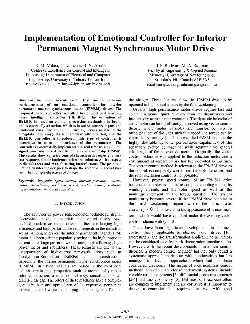
Motivated by the success in functional modeling ofemotions in control engineering applications [10-13], the mainpurpose of this paper is to use a structural model based on thelimbic system of mammalian brain, for decision making andcontrol engineering applications. We have adopted a networkmodel developed by Moren and Balkenius [14], as acomputational model that mimics amygdala, orbitofrontalcortex, thalamus, sensory input cortex and generally, thoseparts of the brain thought to be responsible for processingemotions. There are two approaches to intelligent andcognitive control; direct and indirect approaches. In theindirect approach, the intelligent system is utilized for tuningthe parameters of the controller. One can adopt the first one asthe so called the direct approach. Here the intelligent system,the computational model termed BELBIC, is used as thecontroller block. For sake of simplicity, the term BELBIC iscalled emotional controller in this paper. The model of theproposed BELBIC structure is illustrated in Fig. 1. TheBELBIC technique is essentially an action generationmechanism based on sensory inputs and emotional cues. Ingeneral, these can be vector valued, although in thebenchmarks discussed in this paper for the sake of illustration,one sensory input and one emotional signal ( stress) have beenconsidered. The emotional learning occurs mainly in.amygdala. The learning rule of amygdala is given in Eqn. (8):
1768
AGa = k1. max(O, EC - A) (8)Where Ga is the gain in amygdala connection, k1 is thelearning step in amygdale, and ECand A are the values ofemotional cue function and amygdala output at each time. Theterm max in equation (8) is for making the learning changesmonotonic, implying that the amygdala gain can never bedecreased. This rule is for modeling the incapability ofunlearning the emotion signal (and consequently, emotionalaction), previously learned in the amygdala [14-15]. Similarly,the learning rule in orbitofrontal cortex is given by Eqn. (9) as:AGO=k2.(MO-EC) (9)
where Go is the gain in orbitofrontal connection, k2 is thelearning step in orbitofrontal cortex and MO is the output ofthe whole model (amygdala output), which can be calculatedas:MO = A-0 (10)
in which, 0 represents the output of orbitofrontal cortex.In fact, by receiving the sensory input S, the model
calculates the internal signals of amygdala and orbitofrontalcortex by the following relations in equations (11) and (12),and eventually yields the output as:
A = Ga.SO=Go.S
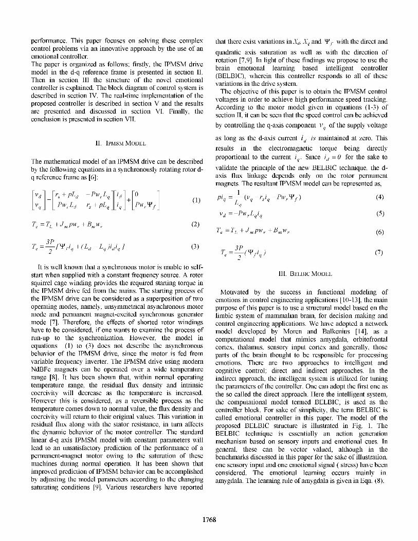
that the input signals have the proper interpretations. Theblock implicitly implemented the criteria: the learningalgorithm and the action selection mechanism used infunctional implementations of emotionally based (or generallyreinforcement learning based) controllers, all at the same time[10-12]. The structure of the control configurationimplemented in this work is illustrated in Fig. 2. The functionsused in emotional cue and sensory input blocks are given bythe following relations:
EC=W1.fedt+W2CO (13)
SI = W3.PO+ W4PO (14)where EC, CO , SI and PO are emotional cue, controlleroutput, sensory input and plant output (IPM motor speed), andthe WI through W4 are gains that must be tuned for designing asatisfactory controller. The gain WI is responsible for tuningthe overshoot, the gain W2 is responsible for tuning the settlingtime, while the gain W3 is responsible for tuning the steadystate error, and finally the gain W4 is responsible forsmoothing the beginning of the response.
(11)(12)
Since amygdala does not have the capability to unlearn anyemotional response that it ever learned, inhibition of anyinappropriate response is the duty of orbitofrontal cortex.
Figure 2. Control system configuration using BELBIC
Emotionalsignal
Figure 1. The basic structure ofBELBIC
A. Emotional controller realizationControllers based on emotional learning have shown very
good robustness and uncertainty handling properties [11-12],while being simple and easy to implement. In order to utilizethis version of the Moren-Balkenius model as a controller forIPMSM drive, it is essential to convert two sets of inputs intothe decision signal as its output. We have implemented aclosed loop configuration using the BELBIC in the feedforward loop of the total system in an appropriate manner so
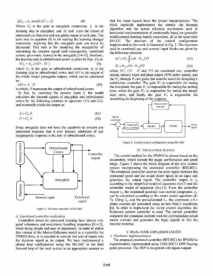
IV. THE CONTROL SYSTEMThe control method for the IPMSM is chosen based on the
parameters, which include the usage, performance and speedrange. Figure 3 shows the block diagram of the new controlsystem incorporating the emotional controller (BELBIC).The emotional controller receives the error signal between thecommand speed and the actual motor speed as an input andgenerates the output signal. The controller output is Vqaccording to the simplified model of equations (4)-(7) and thecontroller model of equations (8)-(14). From the controlleroutput vq, the command quadratic axis current component, IqJcan be calculated according to the motor model equations (4-7). Using Iq, and the pre-calculated Ide, the command a-b-cphase currents are generated using inverse Park's transforms[6]. In order to implement the vector control algorithm, thehysteresis current controller is used. The current controllercompares the command currents with the corresponding actualmotor currents and generates the logic signals to fire theinverter switches.
V. REAL-TIME IMPLEMENTATIONA. Hardware implementation.
The proposed emotional controller (BELBIC) for IPMSM isexperimentally implemented using TMS320C3 1 DSP floatingpoint processor. The DSP is integrated with inputs/outputs
1769
W ( 11 t 1111 i1 l 211 ! I I an(I dfiviig|lab
Coniputurmproit
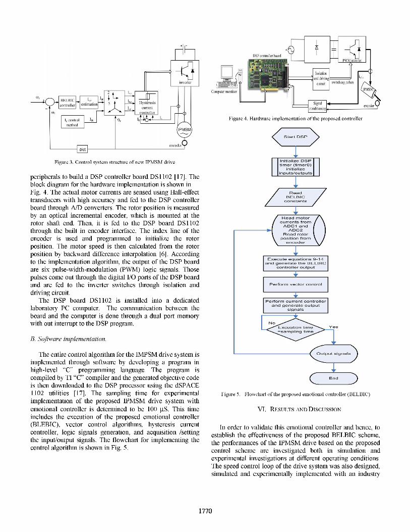
Figure 4. Hardware implementation of the proposed controller
Figure 3. Control system structure ofnew IPMSM drive
peripherals to build a DSP controller board DS1 102 [17]. Theblock diagram for the hardware implementation is shown inFig. 4. The actual motor currents are sensed using Hall-effecttransducers with high accuracy and fed to the DSP controllerboard through A/D converters. The rotor position is measuredby an optical incremental encoder, which is mounted at therotor shaft end. Then, it is fed to the DSP board DS1 102through the built in encoder interface. The index line of theencoder is used and programmed to initialize the rotorposition. The motor speed is then calculated from the rotorposition by backward difference interpolation [6]. Accordingto the implementation algorithm, the output of the DSP boardare six pulse-width-modulation (PWM) logic signals. Thosepulses come out through the digital 1/0 ports of the DSP boardand are fed to the inverter switches through isolation anddriving circuit.
The DSP board DS 1 102 is installed into a dedicatedlaboratory PC computer. The communication between theboard and the computer is done through a dual port memorywith out interrupt to the DSP program.
B. Software implementation.
The entire control algorithm for the IMPSM drive system isimplemented through software by developing a program inhigh-level "C" programming language. The program iscompiled by TI "C" compiler and the generated objective codeis then downloaded to the DSP processor using the dSPACE1102 utilities [17]. The sampling time for experimentalimplementation of the proposed IPMSM drive system withemotional controller is determined to be 100 tS. This timeincludes the execution of the proposed emotional controller(BLEBIC), vector control algorithms, hysteresis currentcontroller, logic signals generation, and acquisition /settingthe input/output signals. The flowchart for implementing thecontrol algorithm is shown in Fig. 5.
Yes
End
Figure 5. Flowchart of the proposed emotional controller (BELBIC)
VI. RESULTS AND DISCUSSION
In order to validate this emotional controller and hence, toestablish the effectiveness of the proposed BELBIC scheme,the performances of the IPMSM drive based on the proposedcontrol scheme are investigated both in simulation andexperimental investigations at different operating conditions.The speed control loop of the drive system was also designed,simulated and experimentally implemented with an industry
1770
standard proportional-integral-derivative (PID)-controller, inorder to compare the performances of those obtained from theproposed BELBIC-based drive system. In order to make a fairjudgment the PID controller is tuned at rated conditions togive the quick and smooth response (settling time and under/over shoot).
overshoot but it lasts for only 0.08 s and the motor startingcurrent, The response in Fig. 6(d) is within the permissiblelimit. Another simulated speed response for a sudden increasein command speed is shown in Fig. 7. It is evident from figure7 that BELBIC technique is also capable of handling thedisturbance in speed command with fast tracking, no
overshoot and zero steady state error. Other simulated speedresponses of the drive for a sudden change in the load torqueare shown in Fig. 8. The load torque is changed from IN-m to3N-m at t= 0.5s. The actual speed does not change during thedisturbance, while the stator current swiftly reaches to its newvalue corresponding to the load applied. This shows thecapability of the new emotional controller in terms ofdisturbance rejection. Thus, perfect speed tracking has beenachieved for the emotional controller (BELBIC).Computer simulations have been carried out to determine
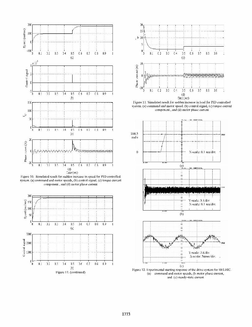
system responses for an industry standard proportional-integral-derivative (PID) controller. The parameters for PIDcontroller of this control system are given in the Appendix.Corresponding simulation results of Figs. 6-8 are obtained forthe PID controller. The simulation results of IPMSM drivewith PID controller are shown in Figs. 9-11. Both Iqc andcontrol signal exhibit large overshoots during transientconditions before the speed settles to its steady-state value.These overshoots are significantly larger than those in theemotional controller (BELBIC). This is also reflected on themotor current. The motor draws more current during transientstates. In all cases using PID controller a steady-state speederror existed. The overall performances with PID controllerare inferior to those of the proposed emotional controller.The simulated results are verified by the experimental tests.
Figure 12 shows the starting responses of the drive systemusing emotional controller. It is to be noted from Fig. 12(a)that the proposed controller gives tuned response in terms offast tracking, overshoot and steady-state error. Also, the motorstarting current is only limited to 2.5 times the rated value as
shown in Fig. 12(b). Moreover, with this controller thehysteresis current controller works perfectly. The motorcurrent follows exactly the command one as shown in Fig.12(c). The experimental speed responses of the drive systemwith step changes of speed from 100 to 188.5 and from 188.5to 100 rad/sec. and the load change for BELBIC technique are
shown in Figs. 13 and 14, respectively. These figures confirmthat the proposed new emotional controller is superior in termsof fast response, zero steady-state error and insensitiveness toload disturbances. Thus, the proposed emotional controller(BELBIC) is robust for high performance drive applications.
TABLE- I. Machine ParametersMotor ratedpower 3-phase, 1 hp
Rated voltage 208 V
Rated current 3A
Rated frequency 60 Hz
Pole pair number (P) 2
d-axis inductance, Lq 42.44 mH
q-axis inductance, Ld 79.57 mH
Stator resistance, R 1.93 Ohm
Motor inertia, Jm 0.003 kgm2Friction Coefficient, Bm 0.001 Nm/rad/s
Magnetic flux constant, 'If 0.311 volts/rad/s
200
X 150
100
IC 50t vl
-50I
300
9 200
t 100
Un
01 02 03 04 05 67 0. 69
0 0 02 03 04 05 06 67 08 69(b)
1o... ..
O 01 0 03 04 0 0 67 M 69(C)
A; -510 0.1 0.2 03 04 05 0.7 0 0.9 1
(d)
TWime (sec)Figure 6. Speed control ofPMSM using BELBIC. (a) command and motorspeeds, (b) control signal, (c) torque current component, and (d) motor phase
Tinfrnsec)Figure 8. Simulation response for sudden increase in load for the proposedcontrol system. (a) command and motor speeds, (b) control signal, (c) torque
current component, and (d) motor phase current.
200 iSO [.. *... ~~....................;) ...3i50 ....................................''''..... ...'...'".''.''.'.''.''"''''' -
I'
0
1 2000
1000Uoo4Figure 7. Simulated response for sudden increase in speed for the proposed
control system. (a) command and motor speeds, (b) control signal, (c) torquecurrent component, and (d) motor phase current
2lUtj ==I,
S 150100
I 50a O
0
0
ri
0 0.1 02 6.3 0.4 0.5 6.6 6.7 0.8 9(a)
0 01 62 6.3 0.4 05 66 67 0.8 6.9(b)
Figure 8. (continued)
20u
10
'u0 1 0.2 0.3 .4 0.5 6.6 67 08 0.9
(a)
01 62 03 0.4 05 66 7 08 69(b)
0 iA 0.2 03 A4 05 66 67 0.8 9(c)
A 0 I
Io0-1
0 0.1 0.2 0.3 6.4 6.5 6.6 07 0.8 6.9(d)
Time (sec)Figure 9. Speed control of PMSM using PID controller. (a) command and
motor speeds, (b) control signal, (c) torque current component, and (d) motorphase current
Figure 10. Simulated result for sudden increase in speed for POD controlledsystem. (a) command and motor speeds, (b) control signal, (c) torque current
component , and (d) motor phase current
0 0.1 02 0.3 .4A 0.5 07
(a)
01 02 0.3 0.4 0.5 O. 07(b)
Figure 001. (continued)
00 09 1
0.0 09
0.7 0 0.9 1
(6)Time (sec)
Figure 01. Simulated result for sudden increase in load for PID controlledsystem. (a) command and motor speed, (b) control signal, (c) torque current
component, and (d) motor phase current
188.5rad/s
0
n~~ ~ ~ ~ ~~Xsae 0. se dix.
(a)
I-------- X-scale: 0.0I sec/div.
(b)
Lk.A, g,L
X-scale: 3msec/div.
(c).--------- ca e: 3A di
-- -scale m1 sec/d iv
(c)
Figure 12. Experimental starting response ofthe drive system for BELBIC.(a) command and motor speeds, (b motor phase current,
and (c) steady-state current
1773
4 n0a9 U
201 F I
150
E 100
U4
b 2000
1000v
- T
0
A.1111 .I .I I.., I. ...- .. .1~ )I
lUUIII U' II
II,I
I
II
A1X1111
... ...
..........
uu. I ui. .6 u.~ u. iT u.~~ U.u
... ...
188
100
X-scale: 0.1I sec/div.
(b)
Figure 13. Experimental speed response of the drive system for a sudden
change in the speed command for BELBIC. (a) command and motor speeds
and (b) motor phase current.
188.5
0
Figure 14. Experimental speed response of the drive system with BELBIC for
a step increase of the load.
VII. CONCLUSION
In this paper, an innovative intelligent controller, BELBIC,
based on mammalian limbic emotional learning algorithmshas been presented. The performance of BELBIC as speed
controller of an IPMSM has been demonstrated. Simulation
and experimental implementation for a laboratory lhp IPMSM
have been verified to demonstrate the effectiveness of this
new emotional controller (BELBIC). The performances of
emotional controller have been compared with those of the
convention PID controller. The proposed emotional controller
has four gains, which give good freedom for choosing desired
responses in terms of overshot, settling time, steady state error
and smoothness. This makes the emotional controller effective
and flexible in high performance applications. Furthermore, it
is strongly felt that an algorithm for optimum tuning of the
BELBIC could make it so much more efficient. It is possibleto pursue other different goals simultaneously or to consider
goal fusion methodologies, e.g. fuzzy aggregation of goals, so
as to form a suitable emotion signal.
APPENDIX
The following parameters of PID controller are chosen as
Kp=14.3927, Ki=5.9946, Kd=0.4332.
REFERENCES
[1] F. Blaschke, "The principle of field orientation as applied to the new
transvector closed-loop control system for rotating-field machines,"
Siemens Reiews., vol. 34, pp. 217 220, May 1972.
[2] V. Utkin, Sliding Modes in Control Optimization: Springer Verlag,
1992.
[3] R. Marino, S. Peresada, and P. Valigri, "Adaptive input-output
linearizing control of induction motors," IEEE Transactions on
Automatatic Control, vol. 38, pp. 208 221, February 1993.
[4] M. Ilic-Spong, R. Marino, S. Peresada, and D. Taylor, "Feedback
linearizing control of switched reluctance motors," IEEE Transactions
on Automatic Control., vol. 32, pp. 371 379, May 1987.
[5] R. Ortega, P. J. Nicklasson, and G. Espinosa, "Passivity-based control of
the general rotating electrical machines," in Proceeding IEEE
Conference Decision and Control, pp. 4018 4023, 1994.
[6] T. S. Radwan, M. A. Rahman, A. M. Osheiba, and A. E. Lashine,
"Dynamic analysis of a high performance permanent magnet
synchronous motor drive," iProeeding IEEE Canadian Conference in
Electrical and Compute Engineering, pp. 611 614, 1996.
L7] M. A. Rahman and P. Lhou, "Analysis ot brushless permanent magnet
synchronous motors", IEEE Transactions on Industrial Electronics, vol.
43, pp. 256-267, April 1996.
[8] T. Sebastian, "Temperature effects on torque production and efficiency
of PM motors using NdFeB magnets," IEEE Transactions on Industry
Applications, vol. 3 1, no. 2, pp. 353-357, March/April 1995.
[9] P. H. Mellor, F. B. Chaaban, and K. J. Binns, "Estimation of parameters
and performance of rare-earth permanent-magnet motors avoidingmeasurement of load angle," Proceedings, Institution of Electrical
Engineers, vol. 133, pp: 322-330,November 1991.
[10] X. Xu, H-G He and D. Hu "Efficient Reinforcement Learning UsingRecursive Least-Squares Methods" Journal of Artificial IntelligenceResearch 16, pp. 259-292, 2002.
[11] M. Fatourechi, C. Lucas, A. Khaki Sedigh "Reducing Control Effort bymeans of Emotional Learning" Proceedings of 9th Iranian Conference
on Electrical Engineering, (ICEE200J), pp: 41-1 to 4 1-8, Tehran, Iran,
May 2001.
[12] M. Fatourechi, C. Lucas, A. Khaki Sedigh "Reduction of Maximum
Overshoot by means of Emotional Learning" Proceedings of 6th Annual
CSI Computer Conference, pp: 460-467, Isfahan, Iran, February 2001.
[13] Jan Moren, Emotion and Learning: A Computational Model of the
Amygdala" Ph.D thesis, ISSN 1101-8453, Lund University Cognitive
Studies 93, Lund University, Sweden, 2002.
[14] J. Moren, C. Balkenius "A Computational Model of Emotional Learning
in The Amygdala" From animals to animals 6: Proceedings of the
International conference on the simulation of adaptive behavior"Cambridge, Mass, The MIT Press, 2000.
[15] C. Balkenius, J. Moren "A Computational Model of Emotional
Conditioning in the Brain" Proceeding of the workshop on GroundingEmotions in Adaptive Systems, Zurich, 1998.
[16] M. A. Rahman, M. Vilathgamuwa, M.N. Uddin and K.J. Tseng, Non-
Linear Control of Interior Permanent Magnet Synchronous Motor",
IEEE Transactions on Industry Applications, vol. 39, no. 2, pp. 569-
575, March/April 2003.
[17] Digital Signal Processing and Control Engineering, Manual Guide,
dSPACE, GmbH, Paderborn, Germany, 1996.
[18] Matlab, Simulink User Guide, The Math works Inc., Natick, MA, 1997.