14
Implementing a High Availability ENOVIA Synchronicity DesignSync Data Manager Solution Dassault Systèmes Technical Whitepaper A Solutions Whitepaper Prepared by Dassault Systèmes

Implementing a High Availability ENOVIA Synchronicity DesignSync Data Manager Solution
Dassault Systèmes Technical Whitepaper
A Solutions WhitepaperPrepared by Dassault Systèmes

Overview and Purpose 4
Prerequisites and Assumptions 4
System Overview 5
GFS Creation using iSCSI 6
Red Hat Cluster Suite Configuration Process 8
ENOVIA Synchronicity DesignSync Data Manager Installation Details 10
Failure Recovery Procedure 10
Conclusion 11
Appendix 12
Implementing a High Availability ENOVIA Synchronicity DesignSync Data Manager Solution
A Product Technical WhitepaperPrepared by Dassault Systèmes

4
Overview and Purpose
Prerequisites and Assumptions
A computer cluster is a group of linked computers working together as a single unit. Cluster components are often connected to each other through fast local area networks and typically implemented to address one of the following four objectives:
• Storage• Load balancing• High performance• High Availability (HA)
HA clusters (also known as failover clusters) are implemented primarily for improving the availability of services. They operate by taking advantage of redundant computers, called nodes, which provide service when system components fail. The most common size of an HA cluster is two nodes, which is the minimum requirement to provide redundancy. HA cluster implementations attempt to use redundancy of
The real-life customer example provided in this paper was implemented using RHEL 4 plus the Red Hat Cluster Suite package. In RHEL 4, the cluster suite package was sold at an additional charge. However, with RHEL 5, the cluster suite package is included as part of the baseline server distribution. It is recommended that customers start with RHEL 5.
Install RHEL 5.X on both the servers (Use of the “XEN” virtualization version of the kernel is not recommended). Be sure to select installation of the cluster management during the OS installation process
cluster components to eliminate single points of failure.
The recent advent of low-cost cluster management offerings have allowed IT organizations to adopt failover techniques for a variety of mission-critical systems including the ENOVIA® Synchronicity® DesignSync® Design Data Management (DDM) product from Dassault Systèmes. Two common vendors in the semiconductor industry are Veritas and Red Hat.
The Red Hat Cluster Suite package (www.redhat.com/cluster_suite) was selected as the basis for this paper because of its low-cost and relatively straightforward implementation. This paper provides a detailed example developed with a current semiconductor customer deploying two production-proven failover systems supporting over 400 ENOVIA Synchronicity DesignSync Data Manager users across three world-wide locations.
as this package is considered optional. Both servers must be communicating with each other across the LAN.
Each server must include the iSCSI Initiator Package. This package can be downloaded from Red Hat Network (RHN) and installed using the rpm utility.
This example assumes a solid IT background, a working knowledge of NetApp filer configuration procedures and ENOVIA Synchronicity DesignSync Data Manager installation experience.
Figure 1: A high-level block diagram of the cluster configuration and LAN connectivity.

5
The ENOVIA Synchronicity DesignSync Data Manager server in this application is considered “virtual” because the Hostname (i.e. “capra”) and IP Address (i.e. 137.57.246.239) do not map to real physical devices. This fake Hostname and IP Address pair is published across the enterprise using DNS or equivalent. On the ENOVIA Synchronicity DesignSync Data Manager side, the use of a “Virtual” Hostname is made possible by leveraging the SYNC_HOSTNAME variable during the installation process which removes
In the hardware setup, the ISCSI connection Netapp3 filer has been connected to the servers with crossover cables. Physical connections are shown in Figure 3.
hostname dependencies. The result is an ENOVIA Synchronicity DesignSync Data Manager installation that is hostname neutral working in conjunction with cluster software that manipulates which physical server responds to the “virtual” IP address.
Specific hardware includes two Sun 4100 servers and a NetApp 3020 storage appliance. Each Sun server uses two Network Interface Cards (NIC) with the NetApp requiring four NICs. (See Figure 2 for details.)
Figure 2
Figure 3
System Overview
Server 1 Server 2 FilerHostname capra3 kolea netapp3
IP Address 1 137.57.246.75 (eth0) 137.57.246.210 (eth0) 137.57.246.X (e0a)
IP Address 2 10.1.1.1 (eth1) 10.10.10.1 (eth1) 137.57.246.X (e0b)
IP Address 3 n/a n/a 10.1.1.2 (e0c)
IP Address 4 n/a n/a 10.10.10.2 (e0d)

6
In this application, the customer chose the use of a GFS based storage environment for the added isolation and security. (If the use of NFS based storage is preferred, this section of the white paper is not relevant.)
o Server 1 (capra3):
1. Set the initiator name in the /etc/initiatorname.iscsi file. An iSCSI node name can also be generated using the iscsi-iname command on the Linux server. The format of the node name is:
iqn.1987-05.com.cisco:RandomNumber
It can also be changed to iqn.1987-05.com.cisco:Hostname
[root@capra3]# more /etc/initiatorname.iscsi ## DO NOT EDIT OR REMOVE THIS FILE! ## If you remove this file, the iSCSI daemon will not start. ## If you change the InitiatorName, existing access control lists ## may reject this initiator. The InitiatorName must be unique ## for each iSCSI initiator. Do NOT duplicate iSCSI InitiatorNames. #InitiatorName=iqn.1987-05.com.cisco:01.bb6be173bc8 # InitiatorName=iqn.1987-05.com.cisco:capra3eth1
2. Edit the /etc/iscsi.conf file and add the filer IP address for the DiscoveryAddress parameter. # grep DiscoveryAddress /etc/iscsi.conf DiscoveryAddress=10.1.1.2
o Server 2 (kolea):
1. Set the initiator name in the /etc/initiatorname.iscsi file.
[root@kolea]# more /etc/initiatorname.iscsi ## DO NOT EDIT OR REMOVE THIS FILE! ## If you remove this file, the iSCSI daemon will not start. ## If you change the InitiatorName, existing access control lists ## may reject this initiator. The InitiatorName must be unique ## for each iSCSI initiator. Do NOT duplicate iSCSI InitiatorNames. #InitiatorName=iqn.1987-05.com.cisco:01.4d28978d171e # InitiatorName=iqn.1987-05.com.cisco:koleaeth1
2. Edit the /etc/iscsi.conf file [root@kolea]# grep DiscoveryAddress /etc/iscsi.conf DiscoveryAddress=10.10.10.2
The filer configuration process involves the creation of two LUNs (Logical Unit Number), which requires the creation of an igroup using each server’s initiator node name. Each LUN must then be mapped to the igroup for each Linux server. Be sure to specify the LUN type and iSCSI igroup type as linux. At least one LUN must be mapped as LUN 0. In our example, the filer volume has been specified as /dev/sdc.
Once completed, you must start the iscsi service on each server:
# /etc/init.d/iscsi
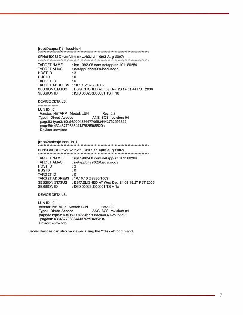
Confirm proper configuration, on each server, using the command below:
GFS Creation using iSCSI
7
[root@capra3]# iscsi-ls -l ****************************************************************************** SFNet iSCSI Driver Version ...4:0.1.11-6(03-Aug-2007) ****************************************************************************** TARGET NAME : iqn.1992-08.com.netapp:sn.101180284 TARGET ALIAS : netapp3.fas3020.iscsi.node HOST ID : 3 BUS ID : 0 TARGET ID : 0 TARGET ADDRESS : 10.1.1.2:3260,1002 SESSION STATUS : ESTABLISHED AT Tue Dec 23 14:01:44 PST 2008 SESSION ID : ISID 00023d000001 TSIH 18
DEVICE DETAILS: --------------- LUN ID : 0 Vendor: NETAPP Model: LUN Rev: 0.2 Type: Direct-Access ANSI SCSI revision: 04 page83 type3: 60a98000433467706834443762596852 page80: 4334677068344437625968520a Device: /dev/sdc
[root@kolea]# iscsi-ls -l ****************************************************************************** SFNet iSCSI Driver Version ...4:0.1.11-6(03-Aug-2007) ****************************************************************************** TARGET NAME : iqn.1992-08.com.netapp:sn.101180284 TARGET ALIAS : netapp3.fas3020.iscsi.node HOST ID : 3 BUS ID : 0 TARGET ID : 0 TARGET ADDRESS : 10.10.10.2:3260,1003 SESSION STATUS : ESTABLISHED AT Wed Dec 24 09:18:27 PST 2008 SESSION ID : ISID 00023d000001 TSIH 1a
DEVICE DETAILS: --------------- LUN ID : 0 Vendor: NETAPP Model: LUN Rev: 0.2 Type: Direct-Access ANSI SCSI revision: 04 page83 type3: 60a98000433467706834443762596852 page80: 4334677068344437625968520a Device: /dev/sdc
Server devices can also be viewed using the “fdisk –l” command.

8
The Red Hat Cluster Suite configuration tasks fall into three broad categories:
• Cluster Nodes The Cluster Nodes tab allows you to specify the nodes (machines) that will comprise the cluster. In our example,
these are “capra3” (Server 1) and “kolea” (Server 2) for a two node cluster.
• Fence Devices A Fence Device is the component of a cluster project that cuts off access to a resource (hard disk, server,
etc.) from a node in your cluster if it loses contact with the rest of the nodes in the cluster. Fencing is often accomplished with a network power switch, which is a power switch that can be controlled through the network. This is known as power fencing. (Our example uses Manual Fencing, which means the “problem” resource will be dealt with using human intervention.)
• Managed Resources Managed Resources include the definition of Failover Domains, Resources and Services.
Invoke the Red Hat Cluster Suite GUI on “capra3” (Server 1) using the command-line option:
[root@capra3]# system-config-cluster &
Selecting the Cluster Configuration tab, the name of our cluster is “Linux-Cluster” which utilizes two nodes called “capra3” and “kolea” (Figure 4).
As explained earlier, this example uses Manual Fencing with a fence name of “sync_fence”. This simplifies the cluster operation, but provides less automation (Figure 5). (Manual fencing was chosen because the customer lacked the necessary hardware to support automation.)
Red Hat Cluster Suite Configuration Process
Figure 4
Figure 5
9
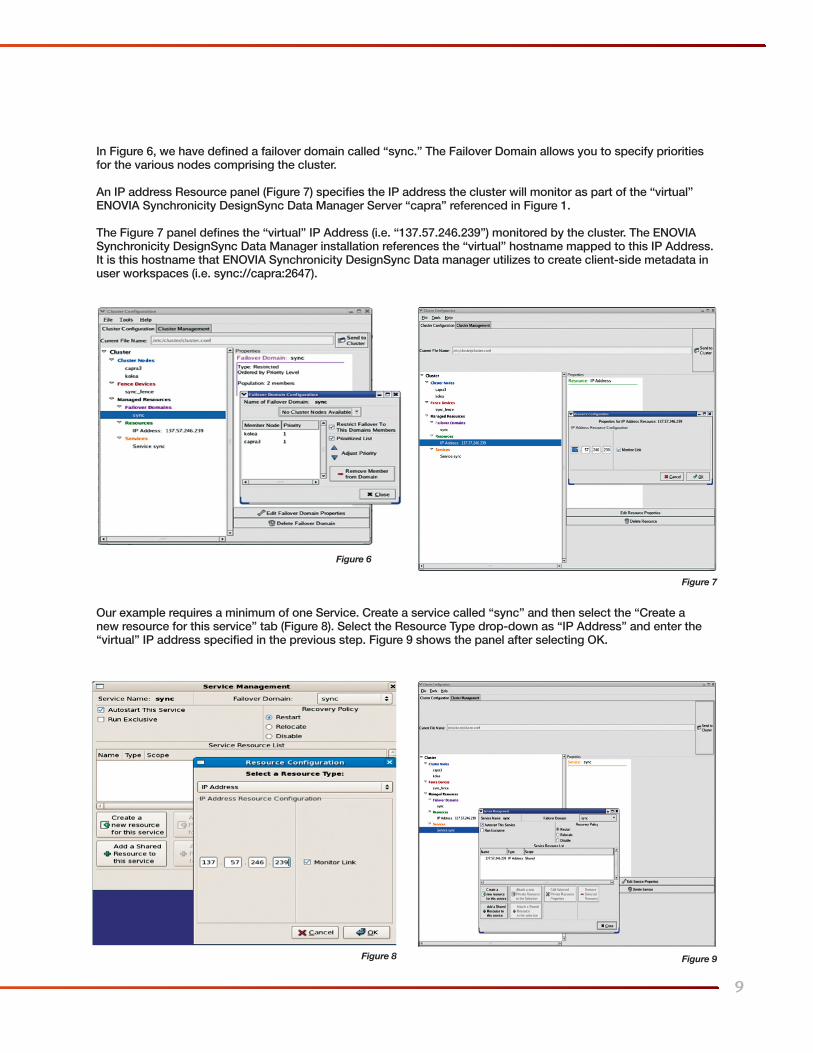
In Figure 6, we have defined a failover domain called “sync.” The Failover Domain allows you to specify priorities for the various nodes comprising the cluster.
An IP address Resource panel (Figure 7) specifies the IP address the cluster will monitor as part of the “virtual” ENOVIA Synchronicity DesignSync Data Manager Server “capra” referenced in Figure 1.
The Figure 7 panel defines the “virtual” IP Address (i.e. “137.57.246.239”) monitored by the cluster. The ENOVIA Synchronicity DesignSync Data Manager installation references the “virtual” hostname mapped to this IP Address. It is this hostname that ENOVIA Synchronicity DesignSync Data manager utilizes to create client-side metadata in user workspaces (i.e. sync://capra:2647).
Our example requires a minimum of one Service. Create a service called “sync” and then select the “Create a new resource for this service” tab (Figure 8). Select the Resource Type drop-down as “IP Address” and enter the “virtual” IP address specified in the previous step. Figure 9 shows the panel after selecting OK.
Figure 6
Figure 8
Figure 7
Figure 9
10
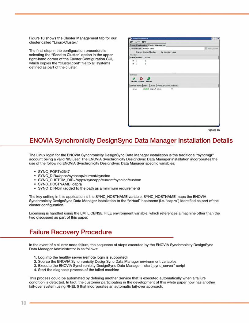
Figure 10 shows the Cluster Management tab for our cluster called “Linux-Cluster.”
The final step in the configuration procedure is selecting the “Send to Cluster” option in the upper right-hand corner of the Cluster Configuration GUI, which copies the “cluster.conf” file to all systems defined as part of the cluster.
Figure 10
The Linux login for the ENOVIA Synchronicity DesignSync Data Manager installation is the traditional “syncmgr” account being a valid NIS user. The ENOVIA Synchronicity DesignSync Data Manager installation incorporates the use of the following ENOVIA Synchronicity DesignSync Data Manager specific variables:
• SYNC_PORT=2647• SYNC_DIR=/apps/syncapp/current/syncinc• SYNC_CUSTOM_DIR=/apps/syncapp/current/syncinc/custom• SYNC_HOSTNAME=capra• SYNC_DIR/bin (added to the path as a minimum requirement)
The key setting in this application is the SYNC_HOSTNAME variable. SYNC_HOSTNAME maps the ENOVIA Synchronicity DesignSync Data Manager installation to the “virtual” hostname (i.e. “capra”) identified as part of the cluster configuration.
Licensing is handled using the LM_LICENSE_FILE environment variable, which references a machine other than the two discussed as part of this paper.
ENOVIA Synchronicity DesignSync Data Manager Installation Details
Failure Recovery Procedure
In the event of a cluster node failure, the sequence of steps executed by the ENOVIA Synchronicity DesignSync Data Manager Administrator is as follows:
1. Log into the healthy server (remote login is supported)2. Source the ENOVIA Synchronicity DesignSync Data Manager environment variables3. Execute the ENOVIA Synchronicity DesignSync Data Manager “start_sync_server” script4. Start the diagnosis process of the failed machine
This process could be automated by defining another Service that is executed automatically when a failure condition is detected. In fact, the customer participating in the development of this white paper now has another fail-over system using RHEL 5 that incorporates an automatic fail-over approach.
11
As mentioned in the opening section of this paper, providing High Availability (HA) Design Data Management systems is more critical than ever. In fact, with the explosion of multi-site/multi-geography design teams witnessed in the semiconductor design community the last 6-8 years, HA systems are becoming the rule rather than the exception. The ever-increasing requirement to support a follow the sun development paradigm demands HA resources. In recent years, the availability of low-cost and easy-to-use cluster management applications has put the goal of cost effective and reliable HA solutions in reach for ENOVIA Synchronicity DesignSync Data Manager customers across the globe.
Conclusion

12
AppendixExample “cluster.conf” File
Shown below is the “cluster.conf” file for the example referenced throughout this paper:
<?xml version=”1.0”?><cluster alias=”Linux-Cluster” config_version=”113” name=”Linux-Cluster”> <fence_daemon post_fail_delay=”0” post_join_delay=”300”/> <clusternodes> <clusternode name=”capra3” nodeid=”1” votes=”1”> <fence> <method name=”1”> <device name=”sync_fence” nodename=”capra3”/> </method> </fence> </clusternode> <clusternode name=”kolea” nodeid=”2” votes=”1”> <fence> <method name=”1”> <device name=”sync_fence” nodename=”kolea”/> </method> </fence> </clusternode> </clusternodes> <fencedevices> <fencedevice agent=”fence_manual” name=”sync_fence”/> </fencedevices> <rm> <failoverdomains> <failoverdomain name=”sync” ordered=”1” restricted=”1”> <failoverdomainnode name=”capra3” priority=”1”/> <failoverdomainnode name=”kolea” priority=”1”/> </failoverdomain> </failoverdomains> <resources> <ip address=”137.57.246.239” monitor_link=”1”/> </resources> <service autostart=”1” domain=”sync” name=”sync”> <ip ref=”137.57.246.239”/> </service> </rm> <cman expected_votes=”1” two_node=”1”/></cluster>

13
PLM Solutions for Your Business
Contact us today to find out how leading companies worldwide are using ENOVIA PLM solutions to beat the competition and speed time-to-market.
About Dassault Systèmes
As a world leader in 3D and Product Lifecycle Management (PLM) solutions, Dassault Systèmes brings value to more than 100,000 customers in 80 countries. A pioneer in the 3D software market since 1981, Dassault Systèmes develops and markets PLM application software and services that support industrial processes and provide a 3D vision of the entire lifecycle of products from conception to maintenance. The Dassault Systèmes portfolio consists of CATIA for designing the virtual product - SolidWorks for 3D mechanical design - DELMIA for virtual production - SIMULIA for virtual testing - ENOVIA for global collaborative lifecycle management, and 3DVIA for online 3D lifelike experiences. For more information, visit http://www/3ds.com.
© Dassault Systèmes, 2009. All Rights Reserved.

SDSDM-TWP-0910
Dassault Systèmes 900 Chelmsford Street, Lowell, Massachusetts 01851 978 442 2500 3DS.com


