Page 1
Important Characteristics of VHDL-AMS and Modelica with Respect to Model Exchange1st International Workshop on Equation-Based Object-OrientedLanguages and Tools, Berlin, July 30, 2007
Olaf Enge-Rosenblatt, Joachim Haase,Christoph Clauß
Fraunhofer Institute for Integrated CircuitsDesign Automation DivisionDresden, Germany
Page 2
2Olaf Enge-Rosenblatt, EOOLT, Berlin, July 30, 2007
©Fr
aunh
ofer
-Ges
ells
chaf
t 20
07
Outline
1. Language characteristics• VHDL-AMS• Modelica
2. Examples• Conservative system• Structural description
3. Comparision of some aspects
4. Transformation of models• Modelica VHDL-AMS• VHDL-AMS Modelica
5. Conclusions
Page 3
3Olaf Enge-Rosenblatt, EOOLT, Berlin, July 30, 2007
©Fr
aunh
ofer
-Ges
ells
chaf
t 20
07
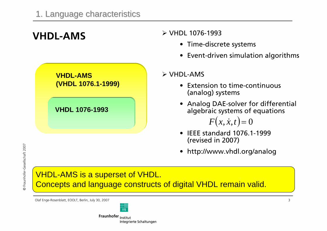
VHDL-AMS(VHDL 1076.1-1999)
VHDL-AMS is a superset of VHDL.Concepts and language constructs of digital VHDL remain valid.
VHDL 1076-1993
1. Language characteristics1. Language characteristics
VHDL 1076-1993
• Time-discrete systems
• Event-driven simulation algorithms
VHDL-AMS
• Extension to time-continuous (analog) systems
• Analog DAE-solver for differentialalgebraic systems of equations
• IEEE standard 1076.1-1999(revised in 2007)
• http://www.vhdl.org/analog
( ) 0,, =txxF &
VHDL-AMS
Page 4
4Olaf Enge-Rosenblatt, EOOLT, Berlin, July 30, 2007
©Fr
aunh
ofer
-Ges
ells
chaf
t 20
07
Modelica
• Object-oriented modelling language
• Description of physical systems based on
– differential equations
– algebraic equations
– discrete equations
• Modelica AssociationModelica Language SpecificationVersion 2.0, July 10, 2002
• http://www.modelica.org
Modelica is a unified language specification for systems characterized by differential-algebraic equations taking into account discrete events for definition of discontinuous behaviour or sampled-signal systems.
Modelica
1. Language characteristics1. Language characteristics
Page 5
5Olaf Enge-Rosenblatt, EOOLT, Berlin, July 30, 2007
©Fr
aunh
ofer
-Ges
ells
chaf
t 20
07
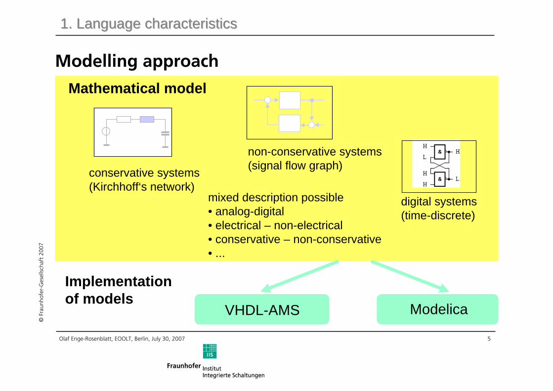
conservative systems(Kirchhoff‘s network)
non-conservative systems(signal flow graph)
digital systems(time-discrete)
mixed description possible• analog-digital• electrical – non-electrical • conservative – non-conservative• ...
Mathematical model
Implementationof models
ModelicaVHDL-AMS
1. Language characteristics1. Language characteristics
Modelling approach
Page 6
6Olaf Enge-Rosenblatt, EOOLT, Berlin, July 30, 2007
©Fr
aunh
ofer
-Ges
ells
chaf
t 20
07
architecture ideal of resistor isquantity v across i through p1 to p2;
beginv == res * i;
end architecture ideal;
library IEEE;use IEEE.electrical_systems.all;
p1 p2
res
p1p2
i
v
2. Examples 2. Examples –– conservative systemconservative system
Resistance model in VHDL-AMS (1)
one instance (obj.-orient.)
entity resistor isgeneric ( res : resistance); -- Resistance [Ohm]port ( terminal p1, p2 : electrical);
end entity resistor;
iresv ⋅=
Page 7
7Olaf Enge-Rosenblatt, EOOLT, Berlin, July 30, 2007
©Fr
aunh
ofer
-Ges
ells
chaf
t 20
07
-- library IEEE_proposedpackage ELECTRICAL_SYSTEMS is
-- subtype declarationssubtype VOLTAGE is REAL tolerance "DEFAULT_VOLTAGE";subtype CURRENT is REAL tolerance "DEFAULT_CURRENT";
-- nature declarationsnature ELECTRICAL is
VOLTAGE acrossCURRENT throughELECTRICAL_REF reference;
-- ...end package ELECTRICAL_SYSTEMS;
Resistance model in VHDL-AMS (2)
2. Examples 2. Examples –– conservative systemconservative system
ELECTRICAL – nature nameto determine physical domain
CURRENT – type of theassociated flow quantity
VOLTAGE – type of theassociated non-flow quantityELECTRICAL_REF – identifierof the electrical referencenode (potential = 0.0)
Page 8
8Olaf Enge-Rosenblatt, EOOLT, Berlin, July 30, 2007
©Fr
aunh
ofer
-Ges
ells
chaf
t 20
07
2. Examples 2. Examples –– conservative systemconservative system
Resistance model in Modelica (1)
partial model OnePort"Component with two electrical pins p and n and current i from p to n" SIunits.Voltage v "Voltage drop between the two pins (= p.v - n.v)";SIunits.Current i "Current flowing from pin p to pin n";Modelica.Electrical.Analog.Interfaces.PositivePin p;Modelica.Electrical.Analog.Interfaces.NegativePin n;
equationv = p.v - n.v;0 = p.i + n.i;i = p.i;
end OnePort;
p.i n.i
p.v n.v
vi
model Resistor "Ideal linear electrical resistor" extends Modelica.Electrical.Analog.Interfaces.OnePort;
parameter SIunits.Resistance R=1 „Resistance";
equationv = R*i;
end Capacitor;
physicaldomain
super class(obj.-orient.)
R
i
p n
viRv ⋅=
Page 9
9Olaf Enge-Rosenblatt, EOOLT, Berlin, July 30, 2007
©Fr
aunh
ofer
-Ges
ells
chaf
t 20
07
2. Examples 2. Examples –– conservative systemconservative system
Resistance model in Modelica (2)// Modelica.Electrical.Analog.Interfaces
connector PositivePin "Positive pin of an electric component" SIunits.Voltage v "Potential at the pin";flow SIunits.Current i "Current flowing into the pin";
end PositivePin;
connector NegativePin "Negative pin of an electric component" SIunits.Voltage v "Potential at the pin";flow SIunits.Current i "Current flowing into the pin";
end NegativePin;
// Modelica.SIunits
type ElectricCurrent = Real (final quantity="ElectricCurrent", final unit="A");type Current = ElectricCurrent ;
type ElectricPotential = Real (final quantity="ElectricPotential", final unit="V");type Voltage = ElectricPotential ;
+
-
Page 10
10Olaf Enge-Rosenblatt, EOOLT, Berlin, July 30, 2007
©Fr
aunh
ofer
-Ges
ells
chaf
t 20
07
2. Examples 2. Examples –– structural descriptionstructural description
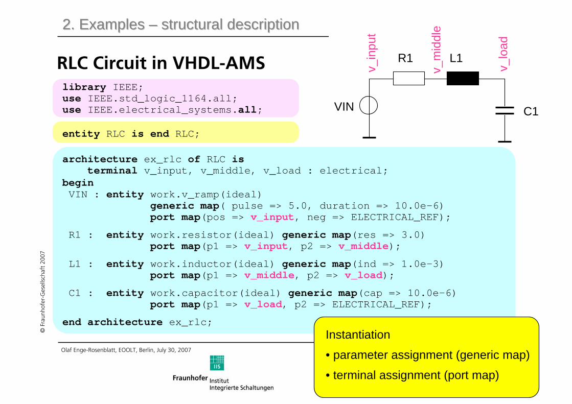
RLC Circuit in VHDL-AMS
VIN
R1 L1
C1
v_in
put
v_m
iddl
e
v_lo
ad
entity RLC is end RLC;
architecture ex_rlc of RLC isterminal v_input, v_middle, v_load : electrical;
beginVIN : entity work.v_ramp(ideal)
generic map( pulse => 5.0, duration => 10.0e-6)port map(pos => v_input, neg => ELECTRICAL_REF);
R1 : entity work.resistor(ideal) generic map(res => 3.0)port map(p1 => v_input, p2 => v_middle);
L1 : entity work.inductor(ideal) generic map(ind => 1.0e-3)port map(p1 => v_middle, p2 => v_load);
C1 : entity work.capacitor(ideal) generic map(cap => 10.0e-6)port map(p1 => v_load, p2 => ELECTRICAL_REF);
end architecture ex_rlc;
library IEEE;use IEEE.std_logic_1164.all;use IEEE.electrical_systems.all;
Instantiation
• parameter assignment (generic map)
• terminal assignment (port map)
Page 11
11Olaf Enge-Rosenblatt, EOOLT, Berlin, July 30, 2007
©Fr
aunh
ofer
-Ges
ells
chaf
t 20
07
V1R1 L1
C1
Gnd1 Gnd2
2. Examples 2. Examples –– structural descriptionstructural description
RLC Circuit in Modelica (1) V1.pR1.p
equationconnect(V1.n, Gnd1.p);connect(V1.p, R1.p);connect(R1.n, L1.p);connect(L1.n, C1.p);connect(C1.n, Gnd2.p); description of
pin connection
used libraries
instances with theirparameters
super classes
end RLC;
model RLC
Modelica.Electrical.Analog.Sources.RampVoltage V1 (V=5,duration=10.0e-6);
Modelica.Electrical.Analog.Basic.Resistor R1(R=3.0);Modelica.Electrical.Analog.Basic.Capacitor C1
(C=10.0e-6, v(start=-5));Modelica.Electrical.Analog.Basic.Inductor L1(L=1.0e-3);Modelica.Electrical.Analog.Basic.Ground Gnd1;Modelica.Electrical.Analog.Basic.Ground Gnd2;
Page 12
12Olaf Enge-Rosenblatt, EOOLT, Berlin, July 30, 2007
©Fr
aunh
ofer
-Ges
ells
chaf
t 20
07
2. Examples 2. Examples –– structural descriptionstructural description
RLC Circuit in Modelica (2)
// Modelica.Electrical.Analog.Basic
model Ground "Ground node" Modelica.Electrical.Analog.Interfaces.Pin p;
equationp.v = 0;
end Ground;
Modelica Language Specification:
connect (a, b)a.across = b.acrossa.through + b.through = 0
connect (a, b)connect (a, c)
a.across = b.across = c.acrossa.through + b.through + c.through = 0
Page 13
13Olaf Enge-Rosenblatt, EOOLT, Berlin, July 30, 2007
©Fr
aunh
ofer
-Ges
ells
chaf
t 20
07
3. Comparison of some aspects3. Comparison of some aspects
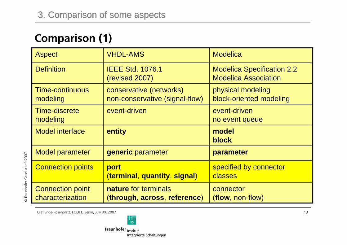
Comparison (1)
physical modelingblock-oriented modeling
conservative (networks) non-conservative (signal-flow)
Time-continuousmodeling
specified by connectorclasses
port(terminal, quantity, signal)
Connection points
connector(flow, non-flow)
nature for terminals(through, across, reference)
Connection pointcharacterization
parametergeneric parameterModel parameter
modelblock
entityModel interface
event-drivenno event queue
event-drivenTime-discretemodeling
Modelica Specification 2.2Modelica Association
IEEE Std. 1076.1 (revised 2007)
Definition
ModelicaVHDL-AMSAspect
Page 14
14Olaf Enge-Rosenblatt, EOOLT, Berlin, July 30, 2007
©Fr
aunh
ofer
-Ges
ells
chaf
t 20
07
3. Comparison of some aspects3. Comparison of some aspects
Comparison (2)
different models for different levels of abstraction
one or more architecturescorresponding to one entity
Organisation
reinit();break statementDiscontinuities
built-in functionsoverloading of operatorsVector operations
initial equationfixed start values
break statementInitial conditions
dynamic variablequantityAnalog waveform
equation orientedexpression1 = expression 2;
equation orientedexpression1 == expression2;
Analog behavior
equation part, algorithmarchitectureModel behavior
ModelicaVHDL-AMSAspect
Page 15
15Olaf Enge-Rosenblatt, EOOLT, Berlin, July 30, 2007
©Fr
aunh
ofer
-Ges
ells
chaf
t 20
07
3. Comparison of some aspects3. Comparison of some aspects
Comparison (3)
smooth ()‘RAMP, ‘SLEWD/A conversion
Connection point orientedInstance orientedNetlists
Widely usedNot supportedInheritance
discrete (Pin)signalDigital waveform
ModelicaVHDL-AMSAspect
Page 16
16Olaf Enge-Rosenblatt, EOOLT, Berlin, July 30, 2007
©Fr
aunh
ofer
-Ges
ells
chaf
t 20
07
4. Transformation of models (Modelica 4. Transformation of models (Modelica VHDLVHDL--AMS)AMS)
Model exchange
Modelica VHDL-AMSpartially automated
Mathematical description
Page 17
17Olaf Enge-Rosenblatt, EOOLT, Berlin, July 30, 2007
©Fr
aunh
ofer
-Ges
ells
chaf
t 20
07
4. Transformation of models (Modelica 4. Transformation of models (Modelica VHDLVHDL--AMS)AMS)
Underlying Branch Structure in Modelica
mp p.i n.i
n.vp.v
Basis for transformation of conservative modelfrom Modelica to VHDL-AMS
Page 18
18Olaf Enge-Rosenblatt, EOOLT, Berlin, July 30, 2007
©Fr
aunh
ofer
-Ges
ells
chaf
t 20
07
Modelica to VHDL-AMS (example Resistor)
library IEEE;use IEEE.ELECTRICAL_SYSTEMS.all;entity RESISTOR is
generic(R : RESISTANCE := 1.0);port (terminal P: ELECTRICAL;
terminal N: ELECTRICAL);end entity RESISTOR;architecture MODELICA of RESISTOR is
quantity P_V across P_I through P;quantity N_V across N_I through N;quantity V : REAL;quantity I : REAL;
beginV == P_V – N_V;0.0 == P_I + N_I;I == P_I;V == R*I;
end architecture MODELICA;
Model correct, but …
partial model OnePort"Component with two pins
….Voltage v "p.v - n.v";….Current i "from p to n";….PositivePin p;….NegativePin n;
equation v = p.v - n.v;0 = p.i + n.i;i = p.i;
end OnePort;
model Resistor "Ideal resistor"
extends….OnePort; parameter ….Resistance R=1;
equationv = R*i;
end Resistor;
4. Transformation of models (Modelica 4. Transformation of models (Modelica VHDLVHDL--AMS)AMS)
Page 19
19Olaf Enge-Rosenblatt, EOOLT, Berlin, July 30, 2007
©Fr
aunh
ofer
-Ges
ells
chaf
t 20
07
Establishing Small (Smart) Models
• group terminals
4. Transformation of models (Modelica 4. Transformation of models (Modelica VHDLVHDL--AMS)AMS)
• connect terminals with norators
• establish (and reduce) network equations
Page 20
20Olaf Enge-Rosenblatt, EOOLT, Berlin, July 30, 2007
©Fr
aunh
ofer
-Ges
ells
chaf
t 20
07
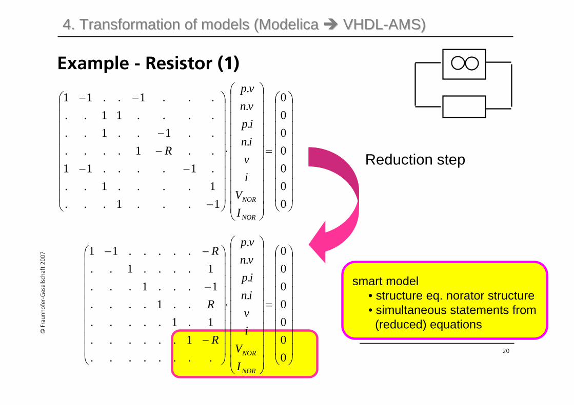
Example - Resistor (1)
⎟⎟⎟⎟⎟⎟⎟⎟⎟
⎠
⎞
⎜⎜⎜⎜⎜⎜⎜⎜⎜
⎝
⎛
=
⎟⎟⎟⎟⎟⎟⎟⎟⎟⎟⎟
⎠
⎞
⎜⎜⎜⎜⎜⎜⎜⎜⎜⎜⎜
⎝
⎛
⋅
⎟⎟⎟⎟⎟⎟⎟⎟⎟
⎠
⎞
⎜⎜⎜⎜⎜⎜⎜⎜⎜
⎝
⎛
−
−−−−
−−
0000000
....
1...1...1....1...1....11..1......1..1......11.....1..11
NOR
NOR
IV
ivinipvnvp
RReduction step
⎟⎟⎟⎟⎟⎟⎟⎟⎟
⎠
⎞
⎜⎜⎜⎜⎜⎜⎜⎜⎜
⎝
⎛
=
⎟⎟⎟⎟⎟⎟⎟⎟⎟⎟⎟
⎠
⎞
⎜⎜⎜⎜⎜⎜⎜⎜⎜⎜⎜
⎝
⎛
⋅
⎟⎟⎟⎟⎟⎟⎟⎟⎟
⎠
⎞
⎜⎜⎜⎜⎜⎜⎜⎜⎜
⎝
⎛
−
−
−−
0000000
....
........1......
1.1.......1....
1...1...1....1..
.....11
NOR
NOR
IV
ivinipvnvp
R
R
R
smart model• structure eq. norator structure• simultaneous statements from
(reduced) equations
4. Transformation of models (Modelica 4. Transformation of models (Modelica VHDLVHDL--AMS)AMS)
Page 21
21Olaf Enge-Rosenblatt, EOOLT, Berlin, July 30, 2007
©Fr
aunh
ofer
-Ges
ells
chaf
t 20
07
Example - Resistor (2)
Only one branch and onesimultaneous statement
architecture IDEAL of RESISTOR is
quantity V_NOR across I_NOR through P to N;
begin
V_NOR == R*I_NOR;
end architecture IDEAL;
4. Transformation of models (Modelica 4. Transformation of models (Modelica VHDLVHDL--AMS)AMS)
Page 22
22Olaf Enge-Rosenblatt, EOOLT, Berlin, July 30, 2007
©Fr
aunh
ofer
-Ges
ells
chaf
t 20
07
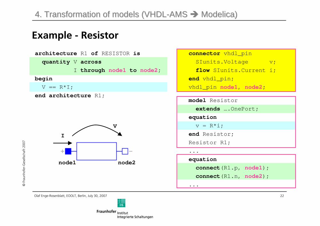
Example - Resistor
architecture R1 of RESISTOR isquantity V across
I through node1 to node2;beginV == R*I;
end architecture R1;
4. Transformation of models (4. Transformation of models (VHDLVHDL--AMS AMS ModelicaModelica))
connector vhdl_pinSIunits.Voltage v;flow SIunits.Current i;
end vhdl_pin;vhdl_pin node1, node2;
model Resistor extends ….OnePort;
equationv = R*i;
end Resistor;Resistor R1;...equationconnect(R1.p, node1);connect(R1.n, node2);
...
node1
I
V
node2
Page 23
23Olaf Enge-Rosenblatt, EOOLT, Berlin, July 30, 2007
©Fr
aunh
ofer
-Ges
ells
chaf
t 20
07
Conclusions• Same mathematical modelling approaches are supported by
VHDL-AMS and Modelica
• Differences result from the semantic approach:- VHDL-AMS comes from electronics- Modelica deals mainly with multi-physics problems
• Potential to transform models from one language into theother
- Special underlying modelling approaches should beconsidered
• Transformation of conservative models from Modelica to VHDL-AMS would be easier if access to the (reduced) modelequations would be possible!
Page 24
24Olaf Enge-Rosenblatt, EOOLT, Berlin, July 30, 2007
©Fr
aunh
ofer
-Ges
ells
chaf
t 20
07
Thank You!