73
Important Considerations in Design of Primary Structural Components: Part 1 Organized by: In collaboration with: Supported by:

1
Important Considerations in Design of Primary Structural Components: Part 1
Organized by: In collaboration with: Supported by:

2
Shear Walls
3
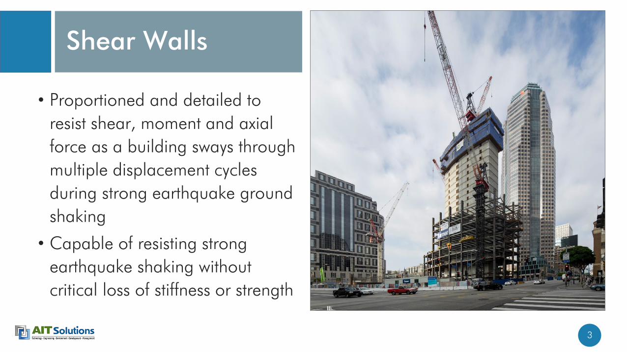
• Proportioned and detailed to
resist shear, moment and axial
force as a building sways through
multiple displacement cycles
during strong earthquake ground
shaking
• Capable of resisting strong
earthquake shaking without
critical loss of stiffness or strength
Shear Walls

4
Wall Proportioning
• ACI 318 has no prescriptive minimum thickness.
• Minimum thickness of 200 mm (8 in.) is a practical lower limit for special
structural walls.
• Construction and performance are generally improved if wall thickness is
at least 300 mm (12 in.) where special boundary elements are used.
• Walls with conventional coupling beams require minimum thickness of
350 mm (14 in.).
• Walls with diagonal reinforced coupling beams require minimum thickness
of 400 mm (16 in.)
5
Wall Reinforcement
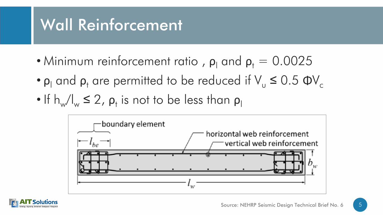
• Minimum reinforcement ratio , ρl and ρt = 0.0025
• ρl and ρt are permitted to be reduced if Vu ≤ 0.5 ΦVc
• If hw/lw ≤ 2, ρt is not to be less than ρl
Source: NEHRP Seismic Design Technical Brief No. 6

6
Minimum Reinforcement in Walls
Source: Table 11.6.1, ACI 318-14

7
Principles for Special Structural Wall Design
• Slender walls (hw/lw ≥ 2)• Tend to behave much like flexural cantilevers
• Preferred inelastic behavior is ductile flexure yielding, without shear failure.
• Squat walls (hw/lw ≤ 0.5)• Resist lateral force in diagonal strut mechanism
• Concrete and distributed horizontal and vertical reinforcement resist shear
• Wall behavior transitions between above extremes for intermediate aspect ratios.

8
Slender Walls
9
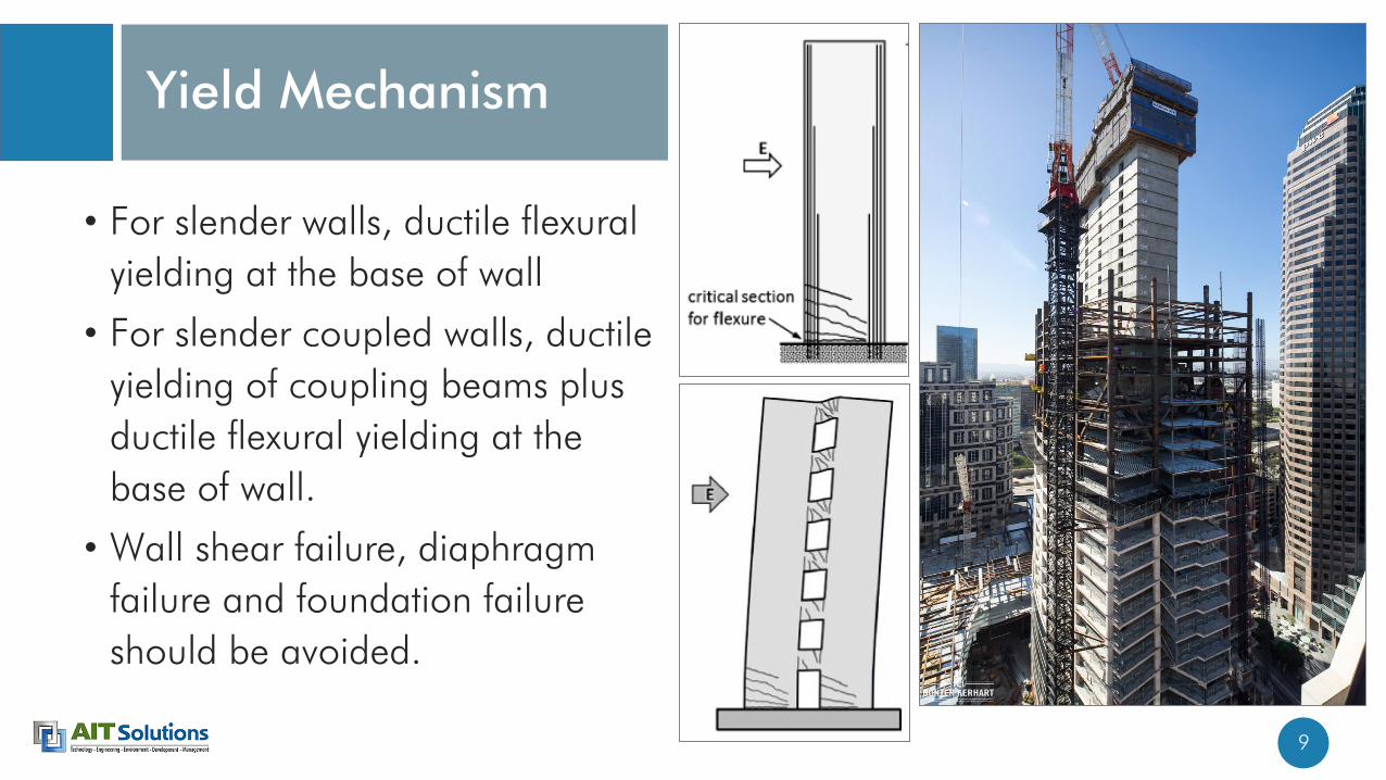
• For slender walls, ductile flexural
yielding at the base of wall
• For slender coupled walls, ductile
yielding of coupling beams plus
ductile flexural yielding at the
base of wall.
• Wall shear failure, diaphragm
failure and foundation failure
should be avoided.
Yield Mechanism

10
• Design selected critical section to have strength in flexure and axial closely matching the required strengths, with some overstrengthprovided at other locations.
• Special details for ductile response can be concentrated around the selected critical section, with relaxed detailing elsewhere.
• In very tall buildings, higher mode response may cause some flexural yielding in intermediate stories.
Yield Mechanism
Source: “Seismic Design of Reinforced Concrete Buildings” by Jack Moehle

11
Achieve Ductile Flexural Yielding
• Key factors for improving cyclic ductility• Keep global compressive and shear stresses low.
• Design confined, stable flexural compression zones.
• Avoid splice failures.
• Axial force well below the balanced point
• UBC 97• Pu ≤ 0.35 P0, which corresponds approximately to the balanced axial force in a
symmetric wall.
• ACI 318• No limit for wall axial force.
• Avoid concrete reaches strain of 0.003 before tension reinforcement yields.

12
Achieve Ductile Flexural Yielding
• Good design practice aims for design shear not exceeding
0.33Φ√f’c Acv to 0.5Φ√f’c Acv so that ductility capacity is not overly
compromised.
• Where flexural ductility demands are low, higher nominal shear
stresses can be tolerated.

13
Concrete Crushing and Reinforcement Buckling
If the compression zone lacks properly detailed
transverse reinforcement, concrete crushing and vertical
reinforcement buckling at a section can result in a locally
weakened “notch” where deformations concentrate,
leading to relatively brittle behavior.
(Chile earthquake, 2010)
Source: NIST GCR 14-917-25

14
Lap Splices
• Lap splices of vertical reinforcement can result in a locally strengthened section, such that yielding, if it occurs, may be shifted above or below the lap.
• Lap splices subjected to multiple yielding cycles can “unzip” unless they are confined by closely spaced transverse reinforcement.
• ACI 318 requires splice lengths at least 1.25 times lengths calculated for fy in tension, with no requirement for confinement.
• Better practice either prohibits lap splices in the intended hinge zone or provides confining transverse reinforcement along the splice length.

15
Lateral Buckling
• Although global wall buckling occurs
when the wall boundary is in
compression, buckling may be
influenced by residual tensile strain in
the wall due to prior loading in the
opposite direction.
• If the boundary yields in tension,
cracked sections are produced, with
crack width dependent on the
amplitude of the reinforcement tensile
strain εsm during the tension excursion.
Slender compression zones can be susceptible to overall buckling.
Lateral buckling of shear wall (Chile earthquake, 2010)
Source: NIST GCR 14-917-25

16
• In a previously yielded wall, crack closure under deformation reversal may require yielding of the longitudinal reinforcement in compression.
• In a wall with two curtains of reinforcement, any slight asymmetry in the reinforcement will result in one curtain yielding before the other, leading to out-of-plane curvature and a tendency to buckle out of plane.
Lateral Buckling
Lateral buckling of shear wall (Christchurch earthquake, 2011)
Source: “Seismic Design of Reinforced Concrete Buildings” by Jack Moehle

17
Lateral Instability of Wall Boundary Previously Yielded in Tension
Source: “Seismic Design of Reinforced Concrete Buildings” by Jack Moehle

18
In U.S. practice,
• hu / b ≤ 10 within intended hinge region
• hu / b ≤ 16 elsewhere
Critical Slenderness Ratio for Wall Boundaries
Source: “Seismic Design of Reinforced Concrete Buildings” by Jack Moehle

19
Advantages to Concentrating Reinforcement at Boundaries
• Provides a convenient zone for
securing transverse
reinforcement for
confinement.
• Enhance curvature capacity
moderately.
• Local reinforcement ratio at
the wall edge is increased,
promoting better distribution
of flexural cracks, yielding
over greater wall height, and
increased displacement
capacity.

20
Advantages to Concentrating reinforcement at Boundaries
• Where reinforcement is uniformly distributed, the local reinforcement ratio at the wall edge is likely to be low.
• In extreme cases, the tensile strength of reinforcement at a cracked section may be less than the concrete tensile strength in adjacent sections, such that only one or few cracks form, leading to localized yielding.
Source: “Seismic Design of Reinforced Concrete Buildings” by Jack Moehle

21
Determine design moment, Mu.
Select location for primary flexural yielding.
Design that critical section to satisfy Mpr,CS ≥ Mu,CS
Define a flexural overstrengthfactor, Φ0 = Mn,CS/Mu,CS.
Amplify design moments, based on overstrength,M’u = Φ0 M’u
Amplify design moments by a dynamic amplification factor ω,
M”u = ωΦ0 M’u
Provide Mn ≥ M”u at every elevation outside the intended
plastic hinge zone.
Source: “Seismic Design of Reinforced Concrete Buildings” by Jack Moehle
Moment Design

22
• Where compressive demands are higher on the edge, ACI 318 requires a special boundary element.
• Where compressive demands are lower, special boundary elements are not required, but ordinary boundary element transverse reinforcement still is required if the longitudinal reinforcement ratio at the wall boundary is greater than 400/fy, psi (2.8/fy, MPa).
• If nominal concrete stress exceeds 0.2 f’c, boundary element required.
• Extend until compressive stress drops below 0.15 f’c.
Boundary Elements Boundary element

23
Special Boundary Element
Source: “Seismic Design of Reinforced Concrete Buildings” by Jack Moehle

24
Ordinary Boundary Element
Source: “Seismic Design of Reinforced Concrete Buildings” by Jack Moehle

25
Boundary Element
Source: “Seismic Design of Reinforced Concrete Buildings” by Jack Moehle

26
Vertical Reinforcement LayoutDetermine type of boundary
element required.
Determine boundary element length
Select trial boundary element reinforcement size and spacing
Select trial size and spacing of vertical reinforcement
Determine P-M strength
Use P-M analysis to check assumed boundary element
length

27
• Select the vertical reinforcement and spread it within the required boundary element length.
• Layout the transverse reinforcement to support verticals and confine the core.
• Iterate until all requirements are met.
Alternative Procedure

28
Shear Design
• Wall shears Vu are determined either from modal response spectrum analysis or equivalent lateral force (ELF) analysis, with seismic forces reduced by response modification coefficient R. • If these shears are used for design without further modification, use Φ = 0.6.
• If the shears are amplified by overstrength factor Φ0 = Mn,CS/Mu,CS, Φ = 0.75.
• Considering that a yielding wall is likely to develop a moment closer to probable moment strength, overstrength factor Φ0 = Mn,CS/Mu,CS, would be more appropriate.
• Typical values of the ratio Mpr,CS/Mu,CS are 1.5 or greater, such that use of this amplification factor along with Φ = 0.75 generally will result in much more conservative design than the other option (unamplified shears with = 0.6).

29
Shear Design
• Vn = Acv (αc λ √f’c + ρt fy)
• Acv = lw bw
• αc = 0.25 MPa if hw/lw ≤ 1.5
• αc = 0.17 MPa if hw/lw ≥ 2.0
• Upper limit
• 0.66Acv √f’c, for all vertical wall segments resisting common lateral force
• 0.83Acv √f’c, for individual vertical wall segments

30
Wall or Column?
• Referring to ACI 318-14, Chapter 2, wall is defined as a vertical element designed to resist axial load, lateral load, or both, with a horizontal length-to-thickness ratio greater than 3.
• In U.S. practice, a wall pier is defined as a relatively narrow vertical wall segment that is essentially a column, but whose dimensions do not satisfy requirements of special moment frame columns (ratio of width to depth is at least 0.4).

31
Wall or Column?
• If lw/bw ≤ 2.5, wall segment shall be designed in accordance with Section 18.10.8.1, satisfying the special moment frame requirements for columns of 18.7.4, 18.7.5, and 18.7.6 (but alternate procedure is not allowed (a) to (f) of Section 18.10.1).
• If 2.5 < lw/bw ≤ 6, wall segment shall be designed in accordance with Section 18.10.8.1, satisfying specified column design requirements or alternate requirements (a) to (f) of Section 18.10.8.1.
• If lw/bw > 6, design as wall.

32
Wall or Column
Source: Table R18.10.1, ACI 318-14

33
Alternate Procedure for Wall Piers (2.5 < lw/bw ≤ 6)
a) Design shear force shall be calculated in accordance with 18.7.6.1 with joint faces taken as the top and bottom of the clear height of the wall pier. If the general building code includes provisions to account for overstrength of the seismic-force-resisting system, the design shear force need not exceed Ωo times the factored shear calculated by analysis of the structure for earthquake load effects.
b) Vn and distributed shear reinforcement shall satisfy 18.10.4.
c) Transverse reinforcement shall be hoops except it shall be permitted to use single-leg horizontal reinforcement parallel to ℓw where only one curtain of distributed shear reinforcement is provided. Single-leg horizontal reinforcement shall have 180-degree bends at each end that engage wall pier boundary longitudinal reinforcement.
d) Vertical spacing of transverse reinforcement shall not exceed 150 mm.
e) Transverse reinforcement shall extend at least 300 mm. above and below the clear height of the wall pier
f) Special boundary elements shall be provided if required by 18.10.6.3.

34
Wall Piers
Source: NIST GCR 14-917-25

35
• A wall region in which forces from adjacent wall segments are resolved
• Panel zone shear strength(recommended in “Seismic Design of Reinforced Concrete Buildings” by Jack Moehle)
Vn = 0.25 √f’c + ρsmin fy ≤ 0.2 f’cρsmin = lesser of distributed reinforcement ratios in the vertical and horizontal directions
• Shear stress limitvu = Φ 0.83 √f’c
Wall Panel Zones
Source: “Seismic Design of Reinforced Concrete Buildings” by Jack Moehle

36
Wall Panel Zones
Source: “Seismic Design of Reinforced Concrete Buildings” by Jack Moehle
(a) Damage in wall from Loma Prieta, California Earthquake (1989)
(b) Inappropriate termination of coupled wall boundary element
(c) Improved detail

37
Wall Panel Zones
Source: “Seismic Design of Reinforced Concrete Buildings” by Jack Moehle
Idealized resolution of wall forces Suggested reinforcement details

38
Performance-based Evaluation of Shear Walls
• Modeling• Inelastic shear wall element
• In-plane flexural response is considered as nonlinear, out-of-plane response is linear.
• Single element with several fibers can be used.
• Confinement effect in concrete is considered.
• Shear response is modeled as linear.
• Evaluation• Axial strain of concrete and reinforcement (Flexural response)
• Shear capacity check

39
Nonlinear Shear Wall Modeling
Steel fibers
Concrete fibers
0
10
20
30
40
50
60
0 0.005 0.01 0.015 0.02 0.025
Stre
ss (M
Pa)
Strain
Concrete stress-strain curves
Unconfined
Fully confined

40
-10
0
10
20
30
40
50
60
70
-0.005 -0.004 -0.003 -0.002 -0.001 0Sto
ry leve
l
Compressive strain
GM-1059
GM-65010
GM-CHY006
GM-JOS
GM-LINC
GM-STL
GM-UNIO
Average
-10
0
10
20
30
40
50
60
70
0 0.0005 0.001 0.0015 0.002 0.0025 0.003
Sto
ry leve
l
Tensile strain
Unco
nfined c
oncr
ete
cru
shin
g s
train
Rein
forc
em
ent yi
eld
ing s
train
Str
ain
lim
it f
or
inte
rmedia
tely
confined c
oncr
ete
Compressive axial strain of concrete Tensile axial strain of vertical rebar
Fully
confined c
oncr
ete
cru
shin
g s
train
, c
= 0
.015
Tensi
on r
uptu
re s
train
lim
it, s
= 0
.05

41
-10
0
10
20
30
40
50
60
70
-200,000 -150,000 -100,000 -50,000 0 50,000 100,000 150,000 200,000
Sto
ry leve
l
Shear force (kN)
GM-1059
GM-65010
GM-CHY006
GM-JOS
GM-LINC
GM-STL
GM-UNIO
AVERAGE
Vn
= 0
.83
Acv√f’
c
Vn
= A
cv(α
cλ√f’
c+
ρtf y
)
Shear design check

42
Coupling Beams

43
• Coupling beams (ln/h ≥ 4)
• Design as special moment frame
beam (Conventional reinforced)
• Coupling beams (ln/h < 2 and
Vu > 0.33λ√(f’c) Acw)
• Design as diagonal reinforced beams
• Other coupling beams (Not
falling within above two limits)
• Design as either special moment
frame beam or diagonal reinforced
beam
Coupling Beams

44
Coupling Beams
Source: “Seismic Design of Reinforced Concrete Buildings” by Jack Moehle

45
Conventional Reinforced Beam
• Flexure Design• Design as special moment frame beams
• Reinforcement placed horizontally at top and bottom
• Shear Design• Shear design is based on probable moment strength (use 1.25 fy)
• Within 2h of member ends, shear strength is calculated based on steel only
• Confinement• Hoops confine at end regions
• If ln/h is relatively small, longitudinal cannot be lapped
• Easier to use closed hoops over entire beam rather than only 2h at each end

46
Conventional Reinforced Beam
Source: “Seismic Design of Reinforced Concrete Buildings” by Jack Moehle
47
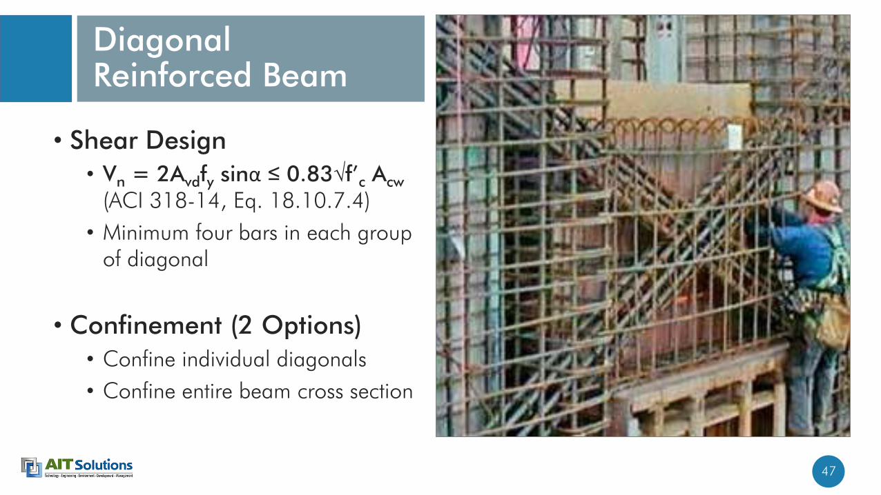
• Shear Design
• Vn = 2Avdfy sinα ≤ 0.83√f’c Acw
(ACI 318-14, Eq. 18.10.7.4)
• Minimum four bars in each group of diagonal
• Confinement (2 Options)
• Confine individual diagonals
• Confine entire beam cross section
Diagonal Reinforced Beam

48
Confine Individual Diagonals
Source: “Seismic Design of Reinforced Concrete Buildings” by Jack Moehle

49
Confine Entire Beam Cross-section
Source: “Seismic Design of Reinforced Concrete Buildings” by Jack Moehle

50
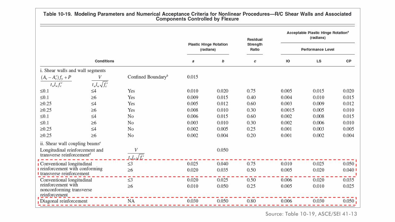
Performance-based Evaluation of Coupling Beams
• Conventional reinforced beam
• Flexural rotations (ASCE 41-13, Table 10-19)
• Shear capacity to satisfy probable shear demand based on moment capacity
• Diagonal reinforced beam
• Shear rotations (ASCE 41-13, Table 10-19)

51
• Conventional reinforced beam
• Moment hinges at the ends of the beam
• Shear response is modeled as linear
• Diagonal reinforced beam
• Shear hinges at the mid span of the beam (Diagonal reinforced beam)
• Considering that there is no shear deformation along the length of the beam
Nonlinear Modeling
Moment hinge (rotational springs) at the ends
Shear-displacement hinge at the mid span
Source: PEER/ATC 72-1 Report
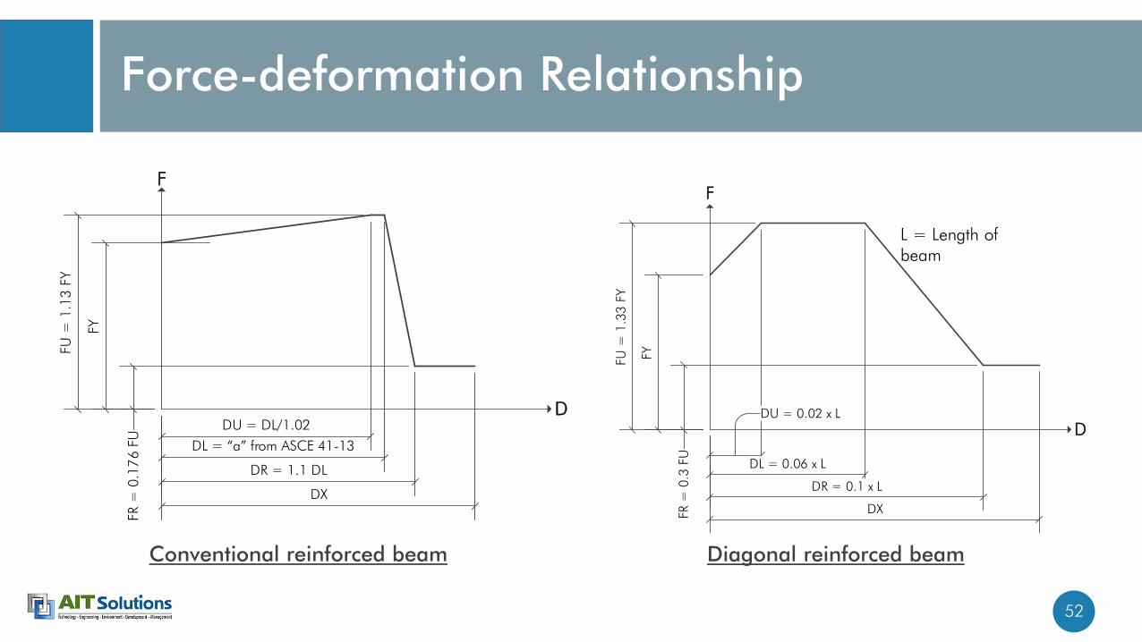
52
Force-deformation Relationship
DU = DL/1.02
FY
FU =
1.1
3 F
Y
DL = a from ASCE 41-13
DR = 1.1 DL
DX
FR =
0.1
76 F
U
F
D DU = 0.02 x L
FYFU =
1.3
3 F
Y
DL = 0.06 x L
DR = 0.1 x L
DXFR =
0.3
FU
F
D
L = Length of beam
Conventional reinforced beam Diagonal reinforced beam
53Source: Table 10-19, ASCE/SEI 41-13

54Source: UCLA-SGEL Report 2009/06Damage levels of conventional reinforced beam

55Source: UCLA-SGEL Report 2009/06Source: UCLA-SGEL Report 2009/06Damage levels of diagonal reinforced beam

56
-10
0
10
20
30
40
50
60
70
0.00 0.01 0.02 0.03 0.04 0.05 0.06
Sto
ry leve
l
Chord rotation of coupling beam (radians)
GM-1059
GM-65010
GM-CHY006
GM-JOS
GM-LINC
GM-STL
GM-UNIO
Average
Collapse
Pre
vention r
ota
tion lim
it
Coupling beam rotation check

57
Post-tensioned Slabs in Seismic Regions

58
• In high seismic regions, post-tensioned (PT) slab-column frames can be used to support gravity loads in conjunction with a lateral-force resisting system (LFRS; e.g., a core wall).
• The LFRS is designed to resist 100% of the design lateral forces as well as to limit lateral displacements to an acceptable level, whereas the slab-column frame must sustain the gravity loads under the expected (design) displacements.
Post-tensioned Slabs in Seismic Regions

59
Post-tensioned Slabs in Seismic Regions
• According to the seismic provisions in ACI 318, structural systems are either designated to resist earthquake forces (i.e., be part of the LFRS) or they are referred to as “nonparticipating” systems or “gravity” force resisting systems (GFRS).
• The lateral displacements imposed on the slab-column frame are likely to introduce significant unbalanced moments on the slab-column connections, increasing the potential for punching failures.

60
• Check gravity load punching
shear D/C ratio vs. story drift.
• If gravity load shear D/C does
not have margin of safety,
allowable story drift under
earthquake will be small.
Code-based procedures (ACI 318-14, Section 18.14.5)
Source: Fig. R18.14.5.1, ACI 318-14
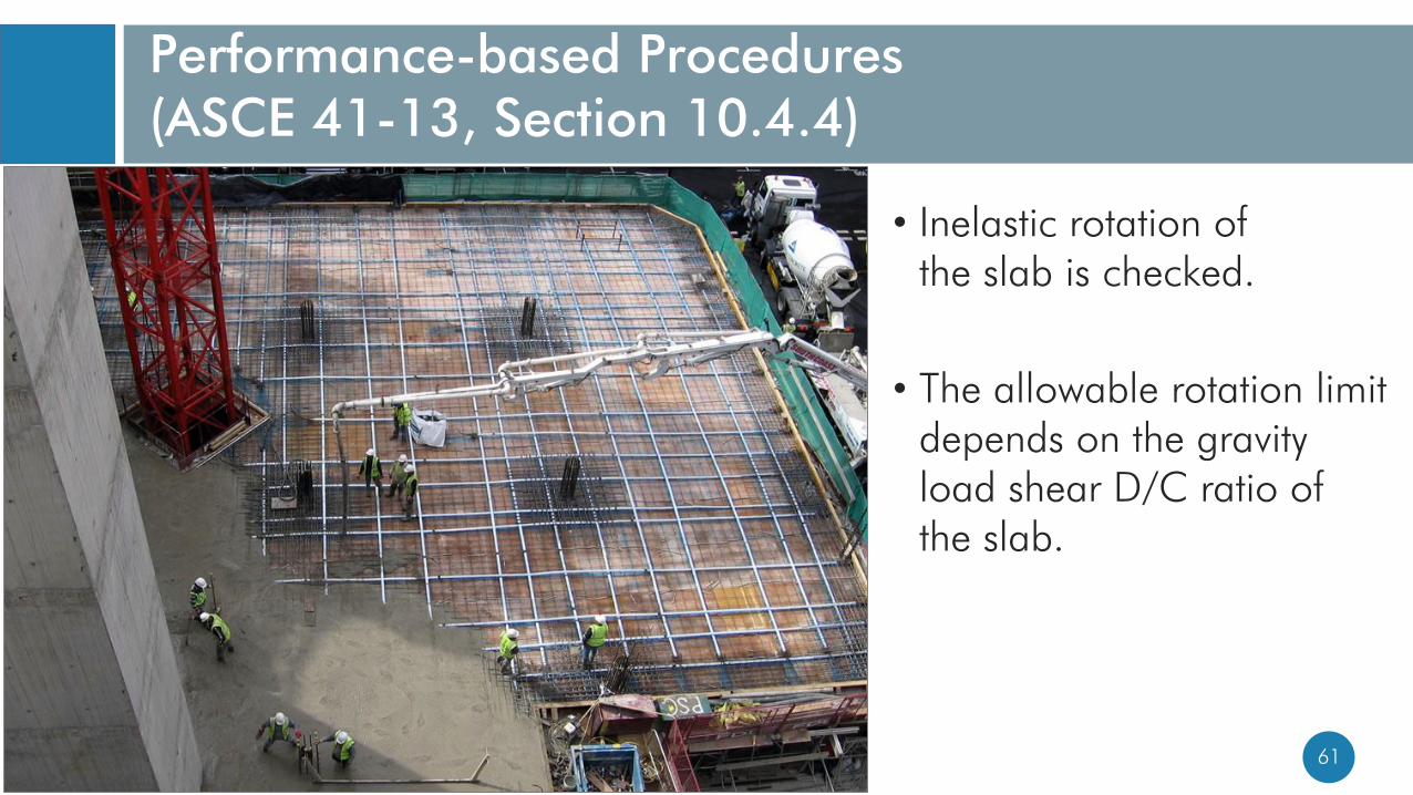
61
• Inelastic rotation of the slab is checked.
• The allowable rotation limit depends on the gravity load shear D/C ratio of the slab.
Performance-based Procedures (ASCE 41-13, Section 10.4.4)

62
Nonlinear Modeling
Source: PEER/ATC 72-1 Report
• Elastic slab effective width• l2 =2c1 + l1/3, for interior frames
• l2 =c1 + l1/6, for exterior frames
• = 1/2 ~ 3/4 for interior frames (Non-prestressed construction)
• = 1/2 ~ 2/3 for interior frames (PT construction)
• Stiffness reduction• = 4c1 / l1(Non-prestressed
construction)
• = 1/2 (PT construction)
c1 is column dimension parallel to slab.

63
Nonlinear Modeling
Source: PEER/ATC 72-1 Report
DU = DL/1.02
FY
FU =
1.1
3 F
Y
DL = a from ASCE 41-13
DR = 1.1 DL
DX
FR =
0.1
76 F
U
F
D
Force-deformation relationship

64Source: Table 10-15, ASCE/SEI 41-13

65
• RC slab• Area of effectively continuous
main bottom bars passing through the column cage in each direction is greater than or equal to 0.5 Vg /(Φfy)
• PT slab• At least one of the
posttensioning tendons in each direction passes through the column cage
Continuity Reinforcement
Source: ACI 352.1R-11
CP limit(Without continuity
reinforcement)
CP limit(With continuity reinforcement)

66
Damage pattern in PT slab at story drift > 3%
Source: Interior “Post-tensioned Slab-column Connections Subjected to Cyclic Lateral Loading”, by Thomas H.-K. Kang, Seong-Hoon Kee, Sang Whan Han, Li-Hyung Lee, and John W. Wallace

67
20
40
60
80
100
120
140
160
180
0.000 0.005 0.010 0.015 0.020 0.025 0.030 0.035 0.040
Ele
vation (
m)
Chord rotation of slab beam (radians)
AJC
IZT
LGP
STG
TAB
UNI
STL
Average
Collapse
Pre
vention r
ota
tion lim
it
Slab-beam rotation check
68
Basement Walls

69
• Out-of-plane flexure and shear (Lateral pressure from soil)
• Inertia component
• Kinematic component
• In-plane shear (force transferred from ground and basement level diaphragms)
Basement Walls

70
Seismic Earth Pressure
• Inertia component• Passive earth pressure due to movement of basement
• Can be determined from lateral displacement of soil springs x soil spring stiffness
• Kinematic componentp = 0.4 kh h Hrw
• p = additional earth pressure caused by seismic shaking
• kh = horizontal seismic coefficient of soil
• Hrw = height of basement wall

71
• Transfer in-plane shear force of diaphragm to basement wall.
• Shear friction reinforcement
Vn = Avf fy
Shear Friction ldldh
Basement wall
Slab
Shear friction reinforcement
Cold joint
Basement wall
Slab
Shear friction reinforcement
Cold joint
l d

72
• Shear capacity is determined
same as shear wall shear
capacity.
• Horizontal reinforcement in
basement wall is considered
as shear reinforcement.
In-plane Shear
In-plane shear from diaphragm