Page 1 of 92 MAN180 rev.4.26.17 Important Safeguards For your protection, please read these instructions completely. Keep this manual for future reference. Carefully observe and comply with all warnings, cautions and instructions placed on the equipment or described in this manual.
Transcript
Page 1 of 92 MAN180 rev.4.26.17
Important Safeguards For your protection, please read these instructions completely. Keep this manual for future
reference. Carefully observe and comply with all warnings, cautions and instructions placed
on the equipment or described in this manual.
Page 2 of 92 MAN180 rev.4.26.17
Contents 1 Safety Information .............................................................................................................................................................................. 6
General Power Tool Safety Warnings ................................................................................................................................. 6
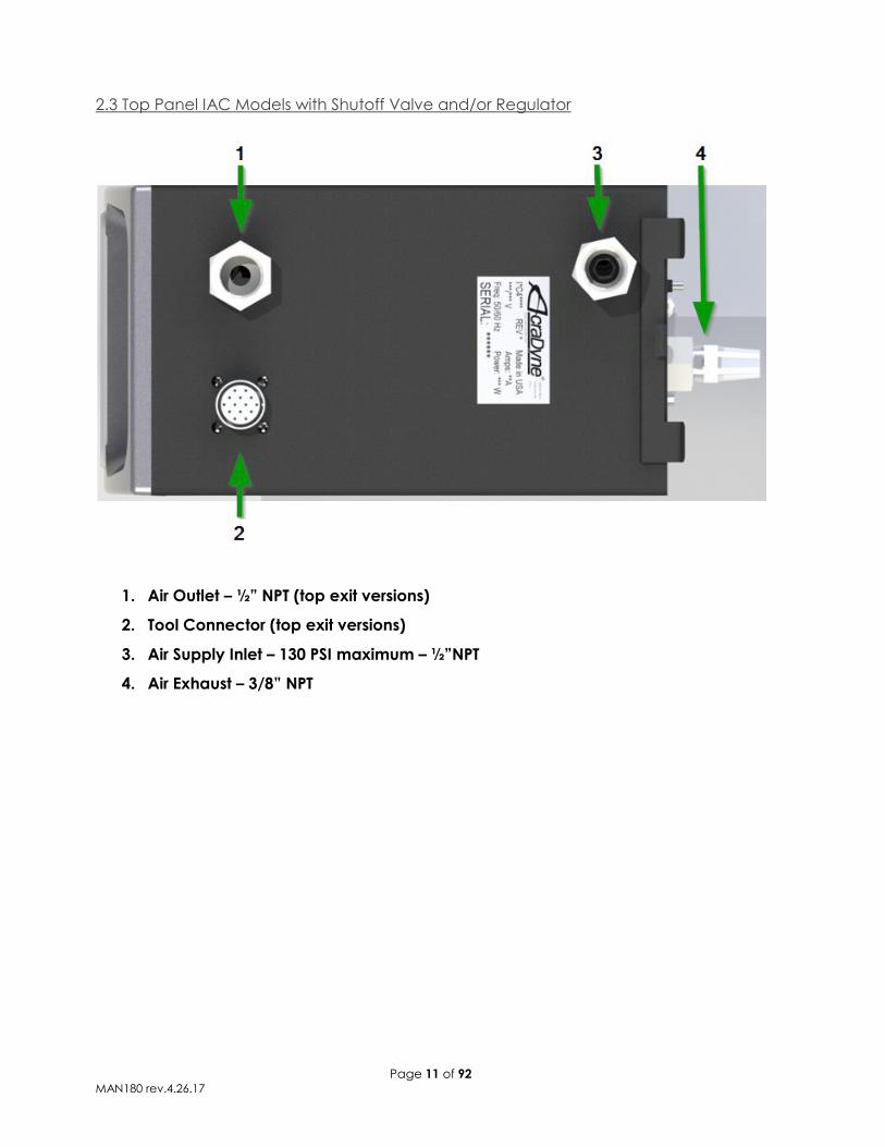
2.3 Top Panel IAC Models with Shutoff Valve and/or Regulator ................................................................................. 11
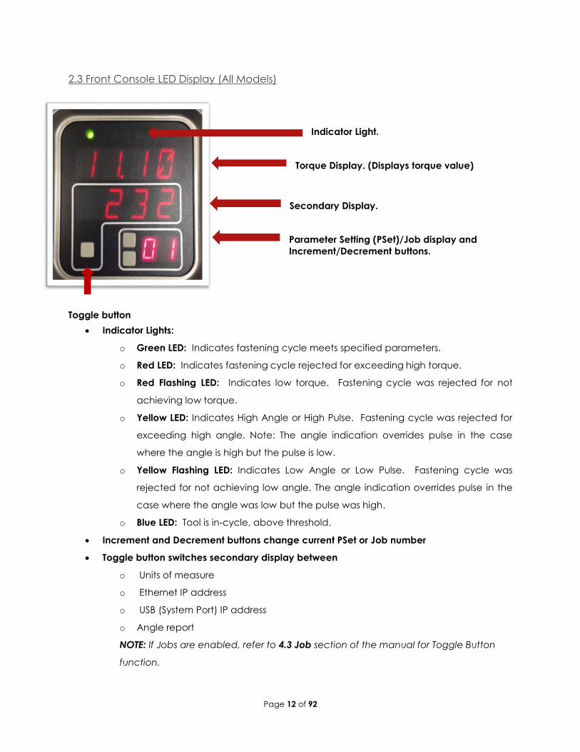
2.3 Front Console LED Display (All Models) ...................................................................................................................... 12
3 Initial Set Up ....................................................................................................................................................................................... 13
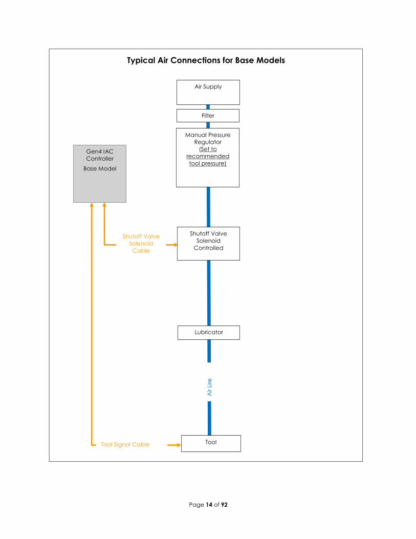
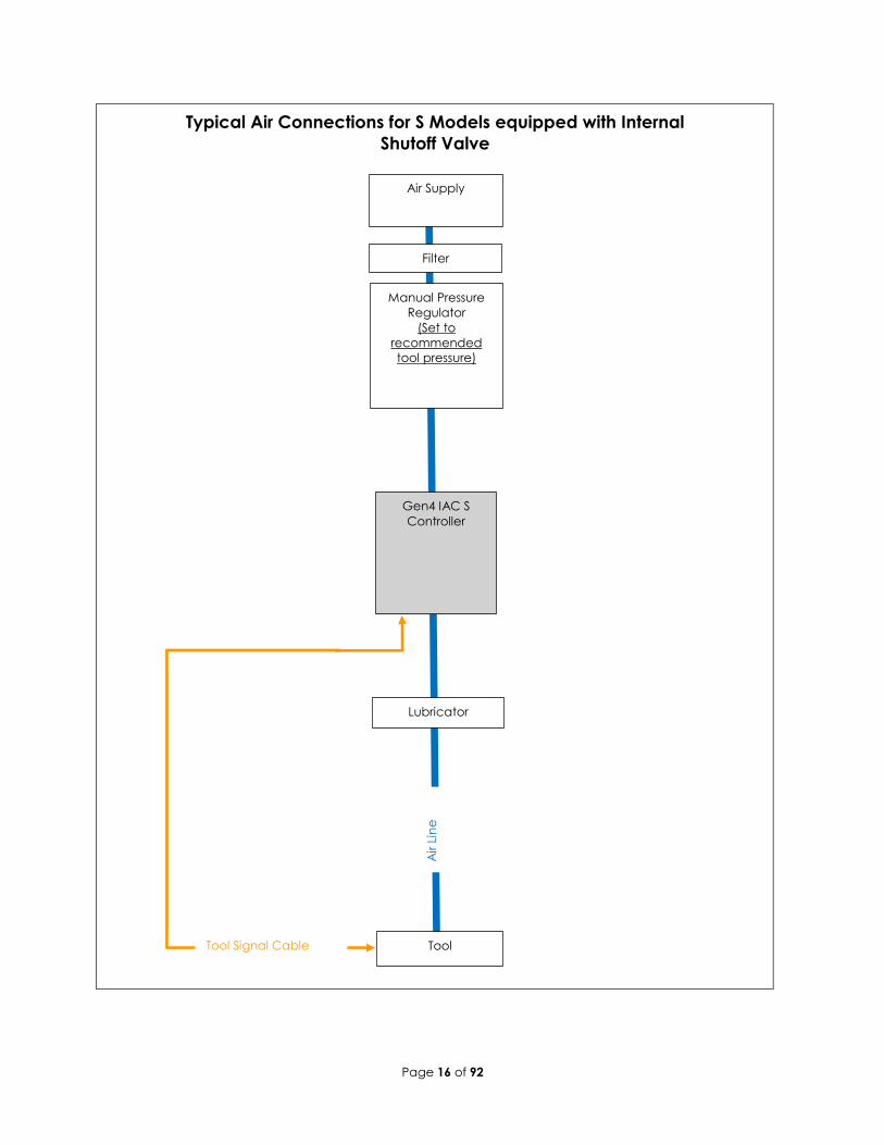
3.1 Air and Electrical Connections .................................................................................................................................... 13
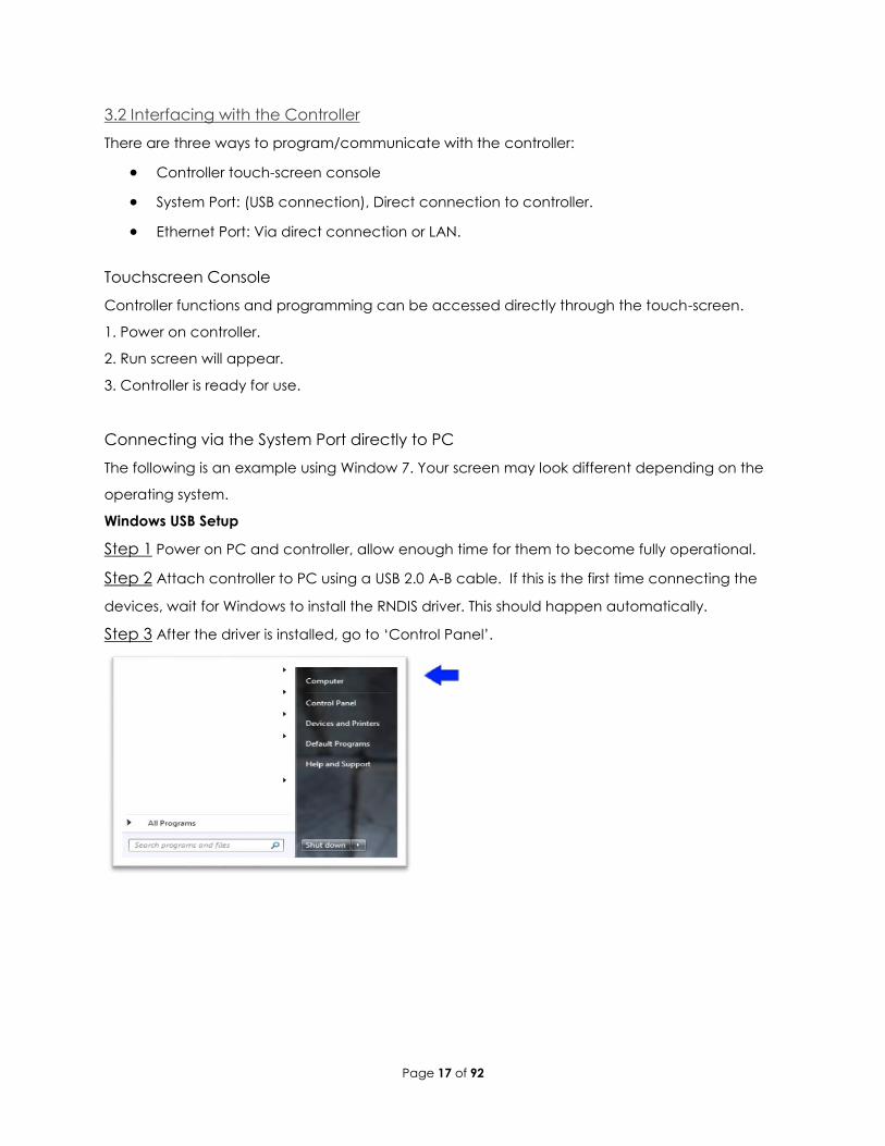
3.2 Interfacing with the Controller ..................................................................................................................................... 17
Connecting via the System Port directly to PC ...................................................................................................... 17
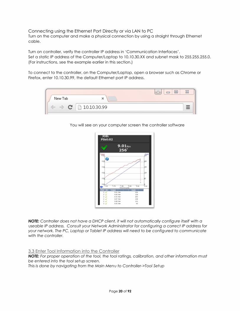
Connecting using the Ethernet Port Directly or via LAN to PC ............................................................................. 20
3.3 Enter Tool Information into the Controller .................................................................................................................. 20
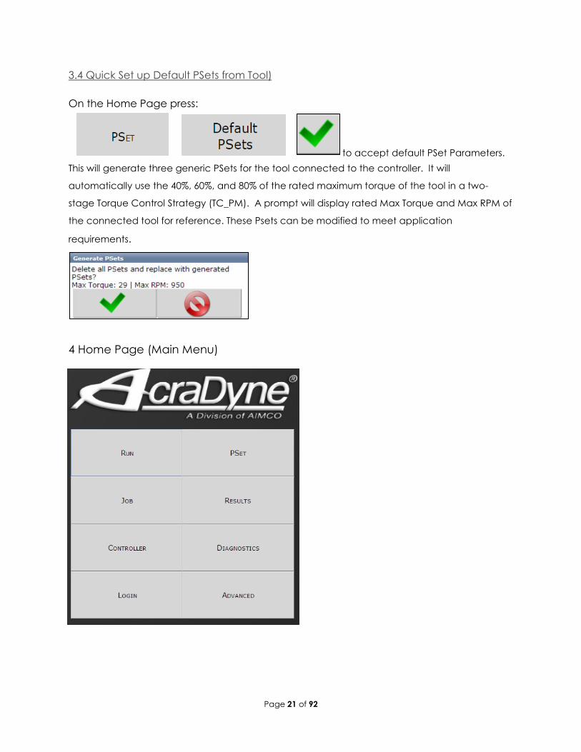
3.4 Quick Set up (Default PSets from Tool) ...................................................................................................................... 21
4 Home Page (Main Menu) ............................................................................................................................................................... 21
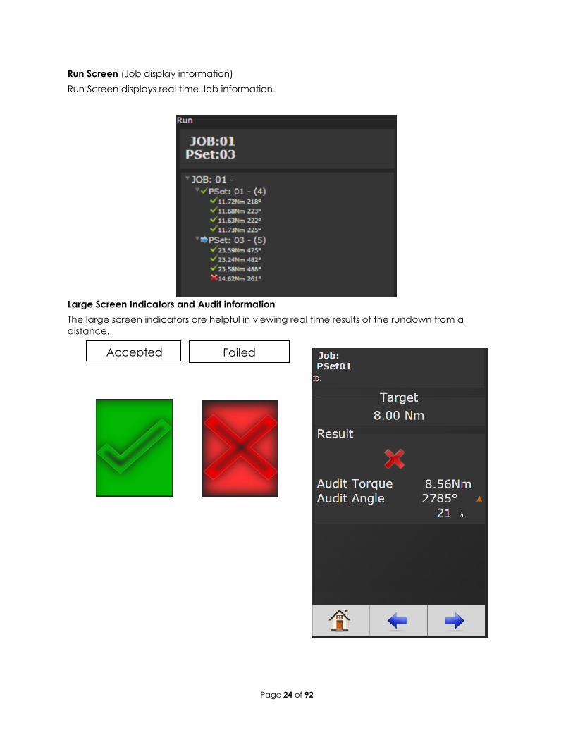
4.1 Run ................................................................................................................................................................................... 22
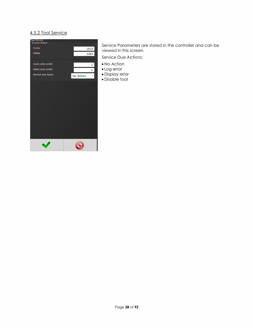
4.5.2 Tool Service ....................................................................................................................................................... 38
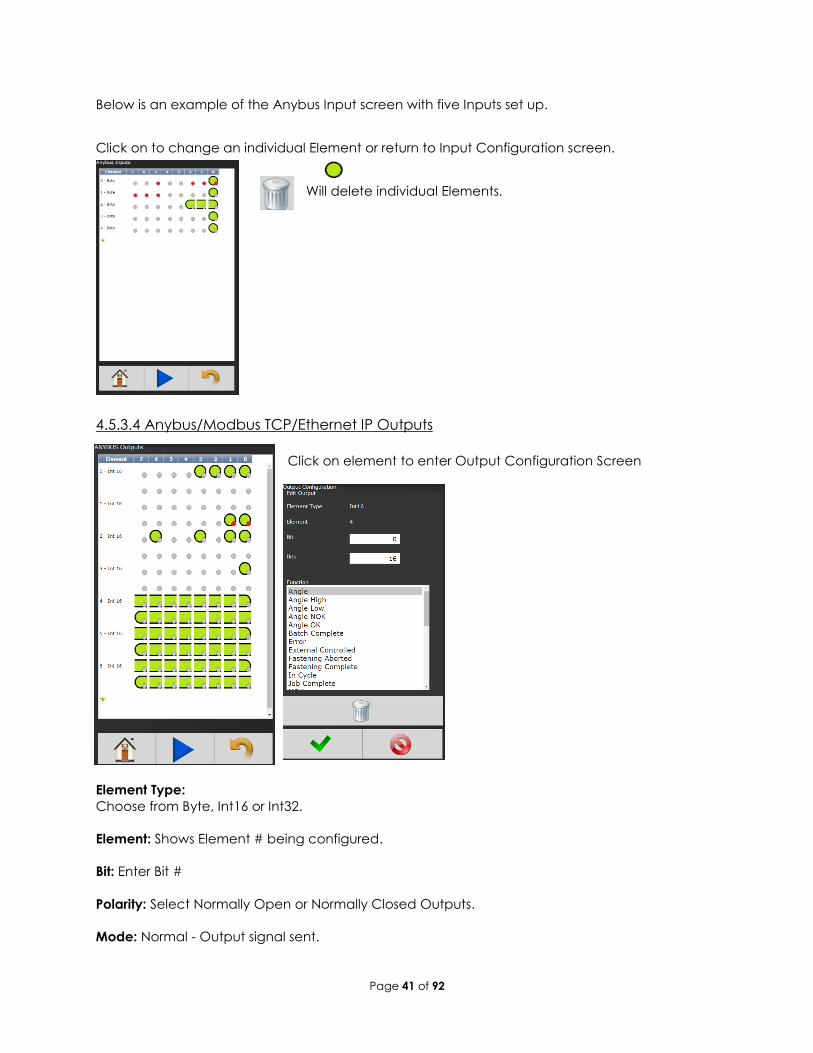
4.5.3.3 Anybus/ Modbus TCP/Ethernet IP Inputs ................................................................................................... 40
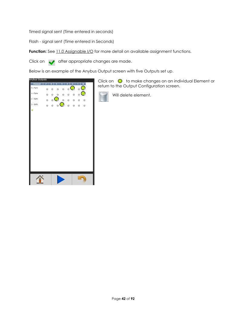
4.5.3.4 Anybus/Modbus TCP/Ethernet IP Outputs .................................................................................................. 41
4.5.4 Communication Interfaces ............................................................................................................................. 43
4.5.4.2 Second Ethernet ........................................................................................................................................... 43
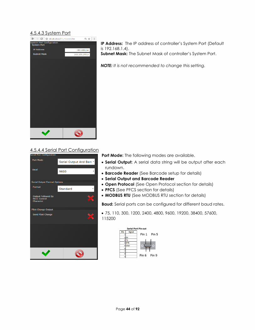
4.5.4.3 System Port .................................................................................................................................................... 44
4.5.4.4 Serial Port Configuration ............................................................................................................................... 44
4.5.4.5 Spindle USB Port ............................................................................................................................................. 46
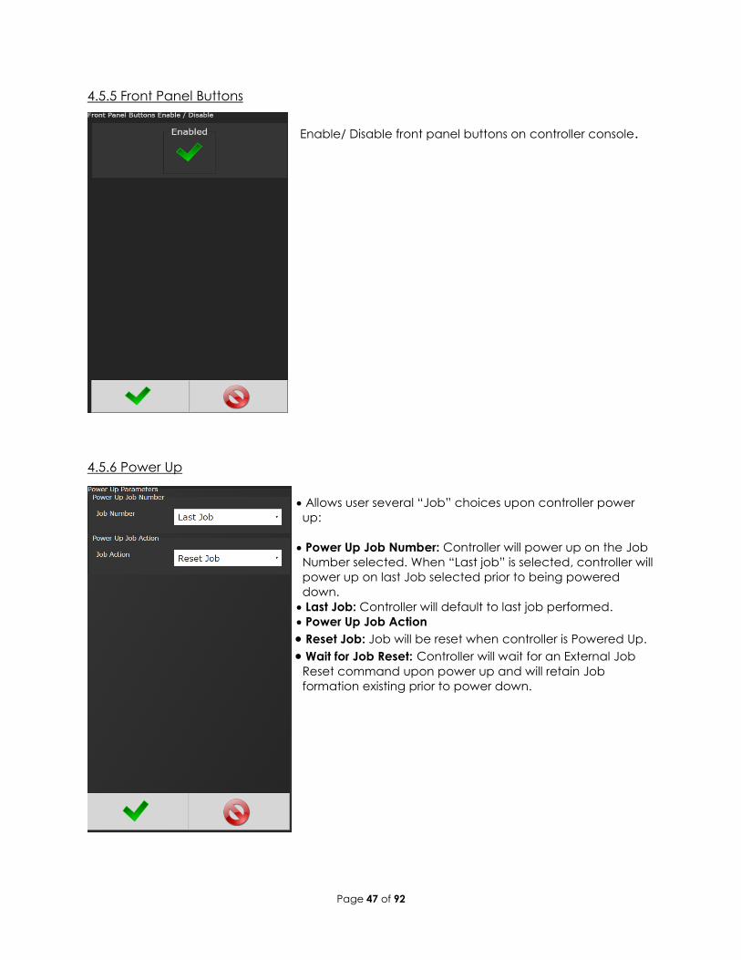
4.5.5 Front Panel Buttons .......................................................................................................................................... 47
4.5.6 Power Up........................................................................................................................................................... 47
Page 3 of 92 MAN180 rev.4.26.17
4.5.7 Bar Code Setup ................................................................................................................................................ 48
4.5.8 Set Time ............................................................................................................................................................. 50
4.5.10 Languages ...................................................................................................................................................... 51
4.6.2 Controller Status ............................................................................................................................................... 52
4.6.3 Live Tool ............................................................................................................................................................ 53
4.6.6 Record Logs ...................................................................................................................................................... 53
4.6.7 System Status .................................................................................................................................................... 54
6 Glossary of Terms .............................................................................................................................................................................. 65
7 Icons Defined .................................................................................................................................................................................... 66
10 24 Volt I/O ....................................................................................................................................................................................... 70
10.1 Port Pinout and Diagrams .......................................................................................................................................... 70
10.2 24 Volt I/O Connections ............................................................................................................................................. 70
Width and Offset .................................................................................................................................................................. 72
Do Nothing ................................................................................................................................................................ 72
Set ID .......................................................................................................................................................................... 73
Set ID (word swap) .................................................................................................................................................... 74
Set Date/Time ............................................................................................................................................................ 74
Page 4 of 92 MAN180 rev.4.26.17
Set Date/Time (word swap) ..................................................................................................................................... 74
Normal ....................................................................................................................................................................... 76
Bits and Start at..................................................................................................................................................................... 78
Ok ............................................................................................................................................................................... 78
Nok ............................................................................................................................................................................. 78
Torque Ok .................................................................................................................................................................. 78
Torque Nok ................................................................................................................................................................ 79
High Torque ............................................................................................................................................................... 79
Angle Ok .................................................................................................................................................................... 79
Angle Nok .................................................................................................................................................................. 79
High Angle ................................................................................................................................................................. 80
In Cycle ...................................................................................................................................................................... 80
Service Indicator ....................................................................................................................................................... 82
Open Protocol Connected ..................................................................................................................................... 82
Running PSet Number ............................................................................................................................................... 82
Running Job Number ................................................................................................................................................ 82
Pulse Ok ..................................................................................................................................................................... 84
Pulse Nok ................................................................................................................................................................... 84
High Angle ................................................................................................................................................................. 84
12 Open Protocol Message IDs ......................................................................................................................................................... 85
• Mainboard Temperature Represents temperature inside
controller.
• CPU Temperature: Represents temperature of CPU.
Page 53 of 92
• Active Faults: Any tool/ controller faults will be shown in this
area.
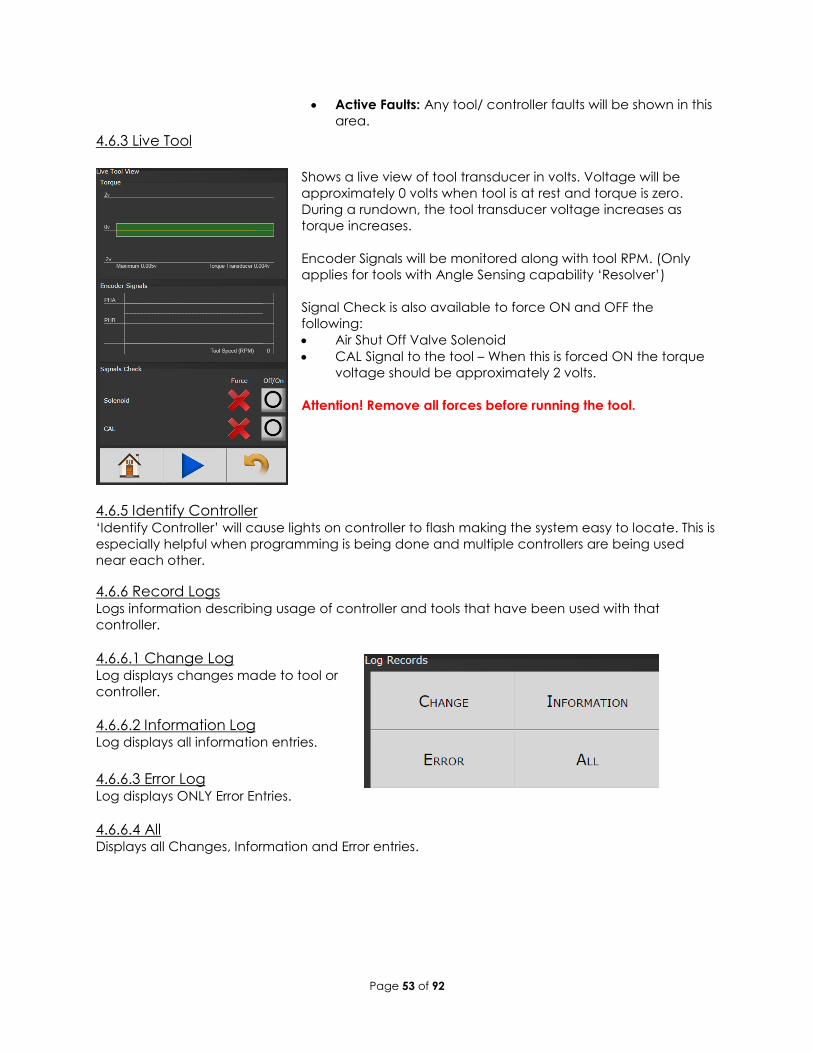
4.6.3 Live Tool
Shows a live view of tool transducer in volts. Voltage will be
approximately 0 volts when tool is at rest and torque is zero.
During a rundown, the tool transducer voltage increases as
torque increases.
Encoder Signals will be monitored along with tool RPM. (Only
applies for tools with Angle Sensing capability ‘Resolver’)
Signal Check is also available to force ON and OFF the
following:
• Air Shut Off Valve Solenoid
• CAL Signal to the tool – When this is forced ON the torque
voltage should be approximately 2 volts.
Attention! Remove all forces before running the tool.
4.6.5 Identify Controller ‘Identify Controller’ will cause lights on controller to flash making the system easy to locate. This is
especially helpful when programming is being done and multiple controllers are being used
near each other.
4.6.6 Record Logs Logs information describing usage of controller and tools that have been used with that
controller.
4.6.6.1 Change Log Log displays changes made to tool or
controller.
4.6.6.2 Information Log Log displays all information entries.
4.6.6.3 Error Log Log displays ONLY Error Entries.
4.6.6.4 All Displays all Changes, Information and Error entries.
Page 54 of 92
4.6.7 System Status
4.7 Login
When a password is required it can be entered in this screen.
Three levels of access to the controller are available:
• Operator: Run/Login screens available.
• Technician: Run/PSet/Job/Diagnostics and Login screens
available.
• Administrator: All screens available.
Page 55 of 92
4.8 Advanced
The ‘Advanced’ menu handles complex settings within the
controller. Detailed descriptions are given below.
4.8.1 Login Setup This screen allows the user to select the default
Login level upon controller start up:
• Operator
• Technician
• Administrator
Page 56 of 92
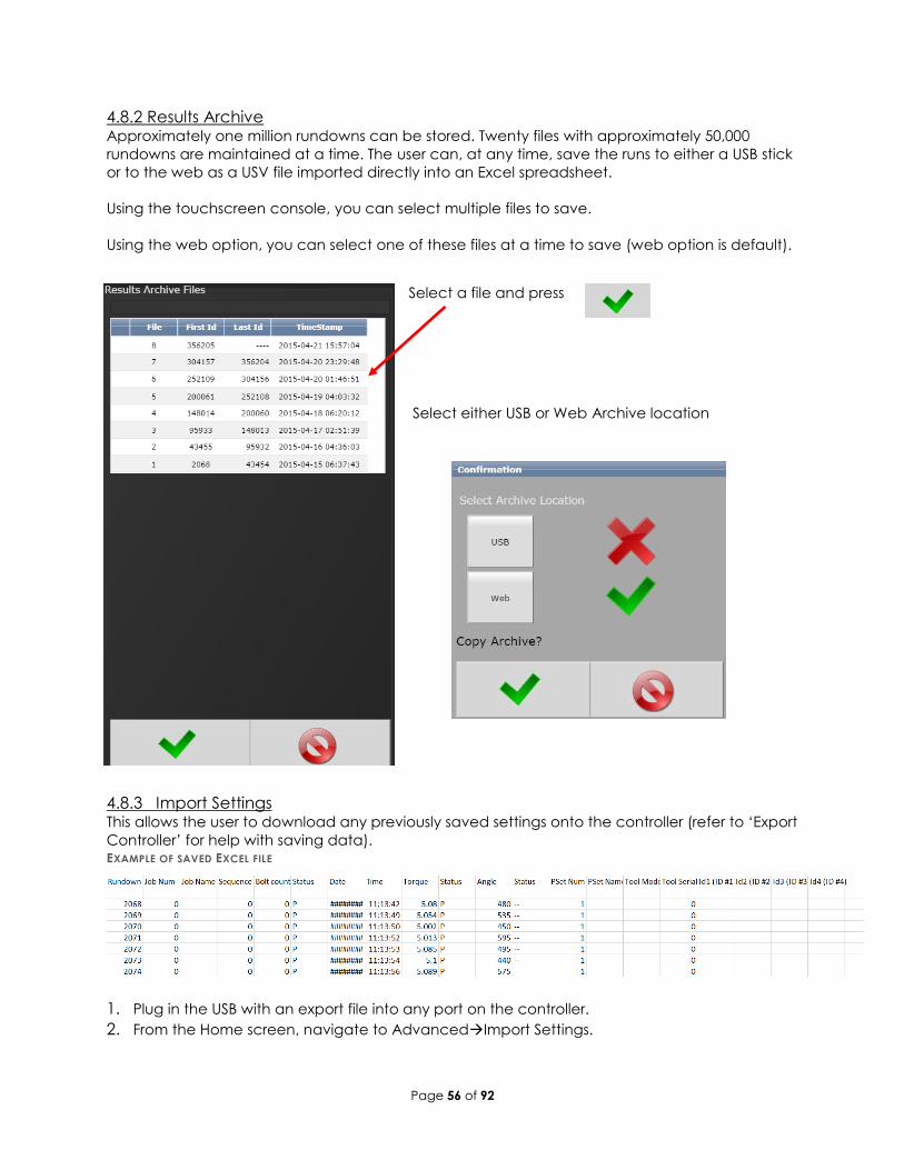
4.8.2 Results Archive Approximately one million rundowns can be stored. Twenty files with approximately 50,000
rundowns are maintained at a time. The user can, at any time, save the runs to either a USB stick
or to the web as a USV file imported directly into an Excel spreadsheet.
Using the touchscreen console, you can select multiple files to save.
Using the web option, you can select one of these files at a time to save (web option is default).
Select a file and press
Select either USB or Web Archive location
4.8.3 Import Settings This allows the user to download any previously saved settings onto the controller (refer to ‘Export
Controller’ for help with saving data).
1. Plug in the USB with an export file into any port on the controller.
2. From the Home screen, navigate to AdvancedImport Settings.
EXAMPLE OF SAVED EXCEL FILE
Page 57 of 92
3. Select the settings to be changed by pressing thus
Changing it to
Configuration: This includes all settings of the controller
except I/O, Master Spindle, Rundowns, PSets
or Jobs.
Operations: This includes PSets and Jobs.
I/O: This includes I/O settings for the local I/O, Anybus, Modbus,
and Ethernet/IP.
Spindle: This includes any Master Spindle setup (i.e. number of
spindles, slave IP addresses, etc.).
4. Press to accept the changes.
5. Press to proceed.
6. Press when the import is complete the controller will restart.
Import settings that were exported from another controller via a USB flash drive. Use this to
“quickly apply” the same settings across several controllers. For example, it is common to have
multiple controllers with the same IO configuration. Set up one controller with the correct IO
configuration and export the controller from Advanced->Export Controller. Now the IO settings
can be imported using this screen.
NOTE: Setting can only be imported from controllers running the same version of software.
4.8.4 Export Controller This allows the user to save Configuration, Operations, I/O, and Spindle settings onto a USB drive.
1. Plug a USB into any port on the controller.
2. From the Home screen, navigate to AdvancedExport Controller.
3. Press to continue, the controller will begin the export process.
4. Press to complete the export.
Page 58 of 92
4.8.5 Update Controller NOTE: Updated firmware versions will typically be sent via email zip file; always save PSet and IP
address information before upgrading controller.
Upgrading the AIMCO IAC Controller
Using the touch-screen or a System Port browser session, navigate to the ‘Advanced’ menu.
Click ‘Update Controller’ and select the latest release. See Figure 1 as an example.
FIGURE 1 AVAILABLE UPDATES
Click the green checkmark when ready.
After the controller restarts, the user should see the messages in Figure 2
FIGURE 2 CONTROLLER UPGRADE NOTIFICATION
When the controller has finished, navigate to DiagnosticsController Overview to view any
changes to the ‘Software Versions’. Any system settings (Ethernet IP address, PSets, Jobs, etc.)
will remain unchanged.
Page 59 of 92
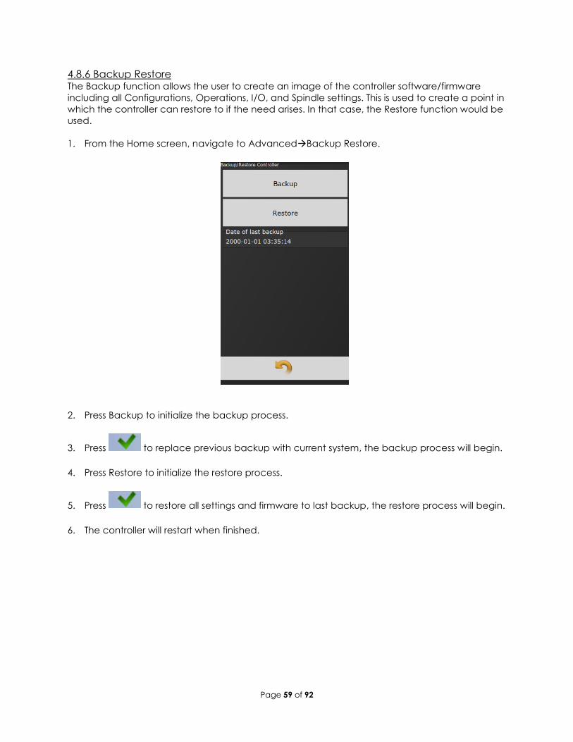
4.8.6 Backup Restore The Backup function allows the user to create an image of the controller software/firmware
including all Configurations, Operations, I/O, and Spindle settings. This is used to create a point in
which the controller can restore to if the need arises. In that case, the Restore function would be
used.
1. From the Home screen, navigate to AdvancedBackup Restore.
2. Press Backup to initialize the backup process.
3. Press to replace previous backup with current system, the backup process will begin.
4. Press Restore to initialize the restore process.
5. Press to restore all settings and firmware to last backup, the restore process will begin.
6. The controller will restart when finished.
Page 60 of 92
4.8.7 Restore Factory Defaults This allows the user to reset the controller’s parameters to factory settings
1. From the Home screen, navigate to AdvancedRestore Factory Defaults.
2. Select the settings to be changed and accept
• Configuration: This includes all settings of the controller
except I/O, Master Spindle, Rundowns, PSets
or Jobs.
• Operations: This includes PSets and Jobs.
• I/O: This includes I/O settings for the local I/O, Anybus, Modbus,
and Ethernet/IP.
• Spindle: This includes any Master Spindle setup (i.e. number of
spindles, slave IP addresses, etc.).
• Rundown: This includes all rundown data /information
• Log: This includes the Change, Information, Error, and Combined
logs.
• Firmware: This includes the firmware/software.
• System: This includes miscellaneous system files.
3. Press to accept the changes.
4. Press to proceed.
5. Press when the restore is complete, the controller
will restart.
Page 61 of 92
4.8.8 Calibrate Touch Screen
Calibrate Touch Screen
Custom and factory default calibrations are available on the controller console.
1. From the Home screen, navigate to AdvancedCalibrate Touch Screen.
2. Press to disable the tool.
changing it to 3. Select the settings to be changed by pressing
4. Press to accept the changes.
5. Press to proceed.
6. Press when the calibration is complete, the controller will restart.
Custom Calibration: This allows the user to create a custom calibration setting for the touch
screen.
NOTE: The controller may need to be reset before the custom calibration is possible.
Factory Default Calibration: This calibrates the touchscreen to the factory defaults.
4.8.9 Soft Reboot Restart the controller without turning the power off.
1. From the Home screen, navigate to AdvancedSoft Reboot.
2. Press to proceed, the controller will restart.
Page 62 of 92
5 Barcode Reader Details
The IAC controller supports the following barcode reader functionality:
• Support up to four identifiers.
• Each rundown result can be associated with up to four identifiers.
• Identifier(s) can be used to select a Parameter Set or a Job.
• Display identifier(s) on controller.
• Ability to lock-out tool until correct identifier(s) is entered.
• Ability to block barcode reads while a Job is in progress.
• Barcode reads (identifiers) can come from any or all the following sources.
o Serial barcode reader
o Open protocol
o Fieldbus network
o Telnet port
Solution Regardless of the source (serial barcode reader, telnet, fieldbus, or protocol), each new string is
passed through the same process:
• All four identifiers are reset to an empty string on power-up.
• Each received barcode is processed through a Barcode Match Table to look for a
match, if one is found the barcode is accepted.
• Each fastening will then be associated with the received barcode(s) until a new one is
received or they are reset.
Parameters The parameters that pertain to the processing of barcode strings:
• The Barcode Match Table is used to identify the newly received barcode string.
• Which of the four Identifiers (ID#1-4) are required to enable the tool?
• Which of the four Identifiers (ID#1-4) to reset on a Job complete?
• Parameter to disable all barcode reads while a Job is in progress. If set, barcode reads
will be disabled after the first fastener is ran until Job is complete.
Barcode Match Table The Barcode Match Table is used to identify which barcode have been received. The controller
can have up to 99 entries (rows) in the table. Each entry has actions that will be performed
when a matching barcode is received. The table is searched from top to bottom to find a
matching barcode; if none are found, the barcode is ignored.
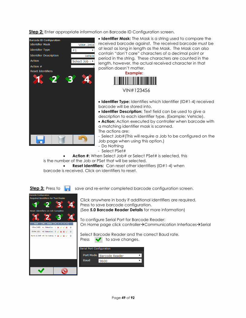
Mask The Mask is a string used to compare against the received barcode. The received barcode
must be at least as long in length as the Mask. The Mask can also contain “don’t care”
characters of a decimal point or period in the string. These “don’t care” characters are
counted in the length but the actual received character in that position doesn’t matter.
Identifier Type The “Identifier Type” field identifies which identifier (ID#1-4) the received barcode will be stored
in.
Page 63 of 92
Action Action can be one of the following:
• None
• Select PS#1-256
• Select Job#1-20
Reset ID The “Reset ID” can reset other identifiers (ID#1-4) when barcode is received.
Examples:
Operator Scans When a vehicle enters the station, the operator scans the VIN. The controller selects the correct
Job number and enables the tool. Each fastener will be identified with this VIN stored locally,
and/or, sent to a server for storage. The Job settings will disable the tool when the Job is
complete.
Setup In this example, there are three possible vehicle types each with its own Job. The barcode scan
will select the correct Job (enabling the tool) and the scan will be stored into ID#1.
Mask ID type Action Reset ID
ID#1 ID#
2
ID#
3
ID#4
“VIN…..7…” ID#1 Select
Job#
1 No No No No
“VIN…..8…” ID#1 Select
Job#
2 No No No No
“VIN…..9…” ID#1 Select
Job#
3 No No No No
The tool enable/disable will be controlled by the Job settings; the correct Job will be selected by
the barcode scan. The “ID Required to Enable the Tool” feature does not need to be utilized.
Required Identifiers for Tool Enable
ID#1 ID#2 ID#3 ID#4
No No No No
These settings are irrelevant as the only way to enable the tool is with a new Job and the only
way to select a new Job is to scan a new barcode.
Reset Identifiers on Job Complete
ID#1 ID#2 ID#3 ID#4
Yes No No No
Page 64 of 92
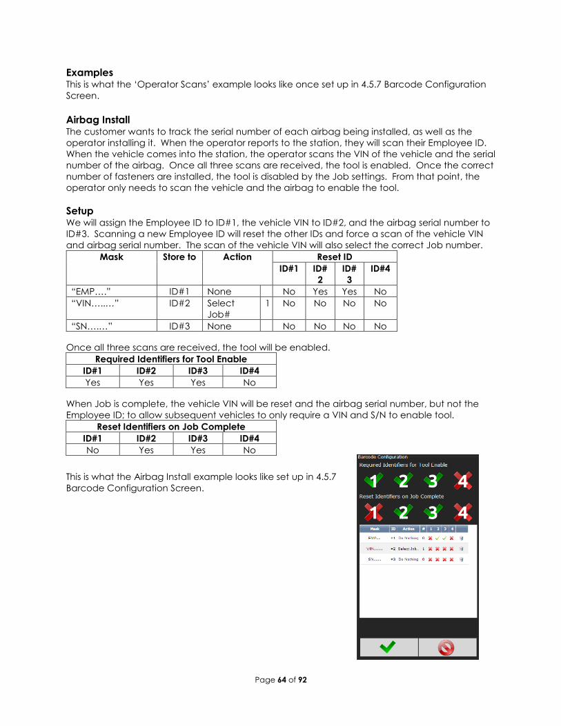
Examples This is what the ‘Operator Scans’ example looks like once set up in 4.5.7 Barcode Configuration
Screen.
Airbag Install The customer wants to track the serial number of each airbag being installed, as well as the
operator installing it. When the operator reports to the station, they will scan their Employee ID.
When the vehicle comes into the station, the operator scans the VIN of the vehicle and the serial
number of the airbag. Once all three scans are received, the tool is enabled. Once the correct
number of fasteners are installed, the tool is disabled by the Job settings. From that point, the
operator only needs to scan the vehicle and the airbag to enable the tool.
Setup We will assign the Employee ID to ID#1, the vehicle VIN to ID#2, and the airbag serial number to
ID#3. Scanning a new Employee ID will reset the other IDs and force a scan of the vehicle VIN
and airbag serial number. The scan of the vehicle VIN will also select the correct Job number.
Mask Store to Action Reset ID
ID#1 ID#
2
ID#
3
ID#4
“EMP….” ID#1 None No Yes Yes No
“VIN…..…” ID#2 Select
Job#
1 No No No No
“SN….…” ID#3 None No No No No
Once all three scans are received, the tool will be enabled.
Required Identifiers for Tool Enable
ID#1 ID#2 ID#3 ID#4
Yes Yes Yes No
When Job is complete, the vehicle VIN will be reset and the airbag serial number, but not the
Employee ID; to allow subsequent vehicles to only require a VIN and S/N to enable tool.
Reset Identifiers on Job Complete
ID#1 ID#2 ID#3 ID#4
No Yes Yes No
This is what the Airbag Install example looks like set up in 4.5.7
Barcode Configuration Screen.
Page 65 of 92
6 Glossary of Terms
Accept Tone Controls tone made from handle of handheld tools for accepted fastening cycles.
Angle Degree fastener rotates from snug, or threshold level, to peak torque.
Cycle Complete Torque level that determines completion of a fastening cycle.
High Angle When peak angle recorded exceeds High Angle, the fastening cycle is
recorded as a reject for High Angle, the High Angle light (solid yellow)
illuminates and fastening cycle is given an overall status of NOK.
High Torque When peak torque recorded exceeds the High Torque, the fastening cycle is recorded as a reject for High Torque, the High Torque light (solid red) illuminates and fastening cycle is given an overall status of NOK.
High Pulse When pulse count recorded exceeds the High Pulse, the fastening cycle is recorded as a reject for High Pulse, the High Pulse light (solid yellow) illuminates and fastening cycle is given an overall status of NOK.
Job A Job is a collection of PSets or Multi-stages, which are useful when performing several multiple fastening operations, each with different requirements. This is convenient since the operator does not have to select a new PSet or Multistage for every fastening.
Low Angle When the peak angle recorded during the Angle Audit Step fails to reach the Low Angle, fastening cycle is recorded as a reject for Low Angle, the low angle light (flashing yellow) illuminates and fastening cycle is given an overall status of NOK.
Low Torque When the peak torque recorded fails to reach the Low Torque, fastening cycle is recorded as a reject for Low Pulse, the Low Pulse light (flashing yellow) illuminates and fastening cycle is given an overall status of NOK.
Low Pulse When the pulse count recorded fails to reach the Low Pulse, fastening cycle is recorded as a reject for Low Torque, the Low Torque light (flashing red) illuminates and fastening cycle is given an overall status of NOK.
Parameter Set A Parameter Set is a collection of instructions that define how the tool
should perform the fastening process. It may be selected from the
console or device such as a socket tray or PC.
In-Cycle Torque Controller begins to monitor tool for angle at a preselected threshold torque. Any increase in angle, after the In-Cycle point, results in a corresponding increase in tension or clamp load within the joint.
Speed Speed at which tool operates during the initial portion of the
fastening cycle prior to downshift.
Spindle A spindle represents a connection to a handheld, or fixtured, tool connected to a controller.
Strategy Identifies the variables being used to control tool during a fastening.
Threshold Torque Sets point at which tool is "In Cycle".
Torque
Calibration
Determines how torque values are assigned to the electrical signals
for torque transducer on tool. Value is unique to each tool and
changes over time.
Torque Target When the tool is being controlled for torque, the torque target instructs
controller when to shutoff tool. Torque target should be greater than
Low Torque and less than High Torque, this is required for torque.
control.
Page 66 of 92
7 Icons Defined
ICON DESCRIPTION FUNCTION WHERE USED
Home Navigation
Button
Navigate to the main menu
(“HOME”) screen.
All screens except
for edit screens.
Run Navigation
Button
Navigate to the Run Screen. All screens except
for edit screens.
Run Screen Select
Buttons
Switch between the
different run screen pages.
Run Screen
Go Back Button Navigate to one menu level
back.
All screens except
for edit screens.
Accept Changes
Button
Accept the changes made
and return to the parent
screen.
Edit screens
Cancel Changes
Button
Reject the changes made
and return to the parent
screen.
Edit screens
Add New Button Add a new item (Pset,
Stage, Job, and other).
PSet and Job edit
screens.
Edit Button Edit selected Item. PSet and Job edit
screens.
Move Up and
Down Buttons
Move selected item up or
down in the sequence
order.
PSet and Job edit
screens.
Copy Button Copy selected Items. PSet, Job, and
other edit screens.
Delete Button Remove or un-assign
selected items.
Edit and list view
screens.
Filter Button Filter Items in a list or table. List view screens.
Save Button Save selected item to file. List view screens.
Disassembly A disassembly event has
been detected.
Run Screen
Pulses Number of pulses during
rundown.
Run Screen (Pulse
tools only).
Page 67 of 92
8 Stop Codes If a Stop condition is detected that prevents the tool from running, a code will appear on the
LED display. Any active stop conditions are also displayed on the RUN screen.
CODE ICON Description
IO
Stopped or Disabled from Physical 24 volt IO input
ABUS
Stopped or Disabled from ANYBUS
MODB
Stopped or Disabled from Modbus
EIP
Stopped or Disabled from Ethernet IP
RTU
Stopped or Disabled from Modbus RTU
OP
Stopped or Disabled from Open Protocol
OP
Lost Open Protocol Connection
REV
Disassembly Disabled
ARM
Tool Requires Arming – MFB button configured to enable the
tool to run.
JOB
Job Sequence Complete
JOB
Job Complete
JOB
XML Count Complete
LOR
Locked on Reject
BRCD
Bar Code ID scan required to enable tool.
SRVC
Tool Disabled For Service - Tool service or calibration interval
has expired.
INVP
Invalid PSet - Parameter set number for a non-existent Pset has
been selected to run. Most likely via one of the following
methods:
o Job
o MFB
o IO
INVP
PSet outside of Job - Parameter set number outside of the job
has been selected. Most likely via one of the following
methods:
o MFB
o IO
INVJ
Invalid Job - Job number for a non-existent Job has been
selected to run. Most likely via one of the following methods:
o MFB
o IO
PSET
PSet Mismatch
SPND
Spindle Not Configured – Spindle selected to run from a Multi-
Spindle Job has not been configured.
Page 68 of 92
NET
XML Disconnected
XML
Stop from XML
NOK
XML Max Rejects Exceeded
FLT
Controller Fault - Error has been detected. See error code list for
details.
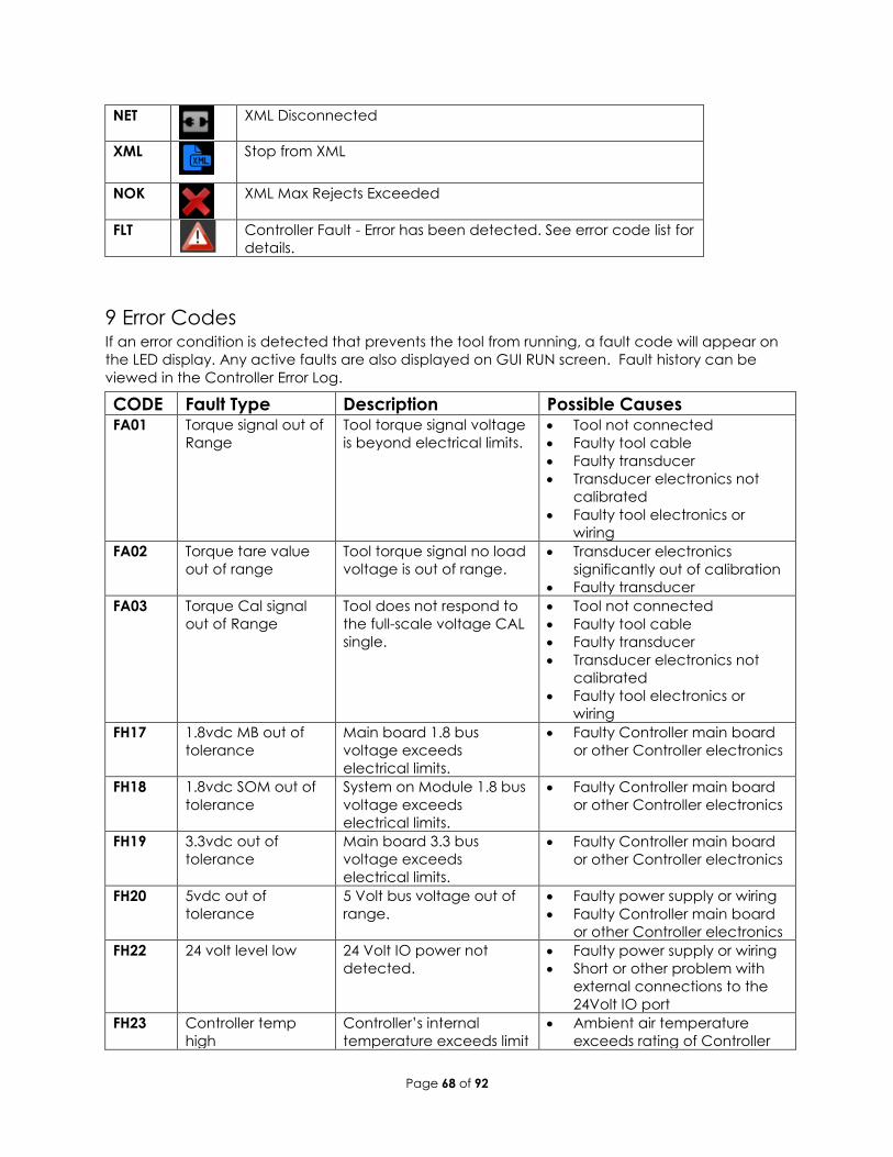
9 Error Codes If an error condition is detected that prevents the tool from running, a fault code will appear on
the LED display. Any active faults are also displayed on GUI RUN screen. Fault history can be
viewed in the Controller Error Log.
CODE Fault Type Description Possible Causes FA01 Torque signal out of
Range
Tool torque signal voltage
is beyond electrical limits.
• Tool not connected
• Faulty tool cable
• Faulty transducer
• Transducer electronics not
calibrated
• Faulty tool electronics or
wiring
FA02 Torque tare value
out of range
Tool torque signal no load
voltage is out of range.
• Transducer electronics
significantly out of calibration
• Faulty transducer
FA03 Torque Cal signal
out of Range
Tool does not respond to
the full-scale voltage CAL
single.
• Tool not connected
• Faulty tool cable
• Faulty transducer
• Transducer electronics not
calibrated
• Faulty tool electronics or
wiring
FH17 1.8vdc MB out of
tolerance
Main board 1.8 bus
voltage exceeds
electrical limits.
• Faulty Controller main board
or other Controller electronics
FH18 1.8vdc SOM out of
tolerance
System on Module 1.8 bus
voltage exceeds
electrical limits.
• Faulty Controller main board
or other Controller electronics
FH19 3.3vdc out of
tolerance
Main board 3.3 bus
voltage exceeds
electrical limits.
• Faulty Controller main board
or other Controller electronics
FH20 5vdc out of
tolerance
5 Volt bus voltage out of
range.
• Faulty power supply or wiring
• Faulty Controller main board
or other Controller electronics
FH22 24 volt level low 24 Volt IO power not
detected.
• Faulty power supply or wiring
• Short or other problem with
external connections to the
24Volt IO port
FH23 Controller temp
high
Controller’s internal
temperature exceeds limit
• Ambient air temperature
exceeds rating of Controller
Page 69 of 92
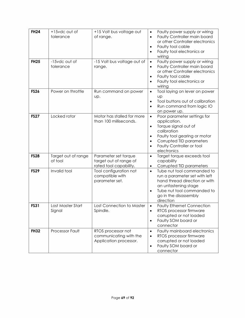
FH24 +15vdc out of
tolerance
+15 Volt bus voltage out
of range.
• Faulty power supply or wiring
• Faulty Controller main board
or other Controller electronics
• Faulty tool cable
• Faulty tool electronics or
wiring
FH25 -15vdc out of
tolerance
-15 Volt bus voltage out of
range.
• Faulty power supply or wiring
• Faulty Controller main board
or other Controller electronics
• Faulty tool cable
• Faulty tool electronics or
wiring
FS26 Power on throttle Run command on power
up.
• Tool laying on lever on power
up
• Tool buttons out of calibration
• Run command from logic IO
on power up.
FS27 Locked rotor Motor has stalled for more
than 100 milliseconds.
• Poor parameter settings for
application.
• Torque signal out of
calibration
• Faulty tool gearing or motor
• Corrupted TID parameters
• Faulty Controller or tool
electronics
FS28 Target out of range
of tool
Parameter set torque
target out of range of
rated tool capability.
• Target torque exceeds tool
capability
• Corrupted TID parameters
FS29 Invalid tool Tool configuration not
compatible with
parameter set.
• Tube nut tool commanded to
run a parameter set with left
hand thread direction or with
an unfastening stage
• Tube nut tool commanded to
go in the disassembly
direction
FS31 Lost Master Start
Signal
Lost Connection to Master
Spindle.
• Faulty Ethernet Connection
• RTOS processor firmware
corrupted or not loaded
• Faulty SOM board or
connector
FH32 Processor Fault RTOS processor not
communicating with the
Application processor.
• Faulty mainboard electronics
• RTOS processor firmware
corrupted or not loaded
• Faulty SOM board or
connector
Page 70 of 92
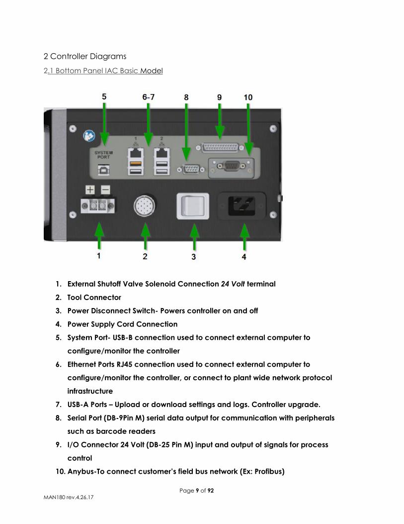
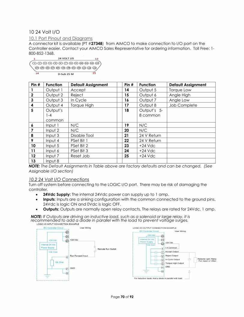
10 24 Volt I/O
10.1 Port Pinout and Diagrams A connector kit is available (PT #27348) from AIMCO to make connection to I/O port on the
Controller easier. Contact your AIMCO Sales Representative for ordering information. Toll Free: 1-
800-852-1368.
Pin # Function Default Assignment Pin # Function Default Assignment
1 Output 1 Accept 14 Output 5 Torque Low
2 Output 2 Reject 15 Output 6 Angle High
3 Output 3 In Cycle 16 Output 7 Angle Low
4 Output 4 Torque High 17 Output 8 Job Complete
5 Output’s
1-4
common
18 Output’s 5-
8 common
6 Input 1 N/C 19 N/C
7 Input 2 N/C 20 N/C
8 Input 3 Disable Tool 21 24 V Return
9 Input 4 PSet Bit 1 22 24 V Return
10 Input 5 PSet Bit 2 23 +24 Vdc
11 Input 6 PSet Bit 3 24 +24 Vdc
12 Input 7 Reset Job 25 +24 Vdc
13 Input 8
NOTE: The Default Assignments in Table above are factory defaults and can be changed. (See
Assignable I/O section)
10.2 24 Volt I/O Connections Turn off system before connecting to the LOGIC I/O port. There may be risk of damaging the
controller.
• 24Vdc Supply: The internal 24Vdc power can supply up to 1 amp.
• Inputs: Inputs are a sinking configuration with the common connected to the ground pins.
24Vdc is logic ON and 0Vdc is logic OFF.
• Outputs: Outputs are normally open relay contacts. The relays are rated for 24Vdc, 1 amp. NOTE: If Outputs are driving an inductive load, such as a solenoid or large relay, it is recommended to add a diode in parallel with the load to prevent voltage surges.
Page 71 of 92
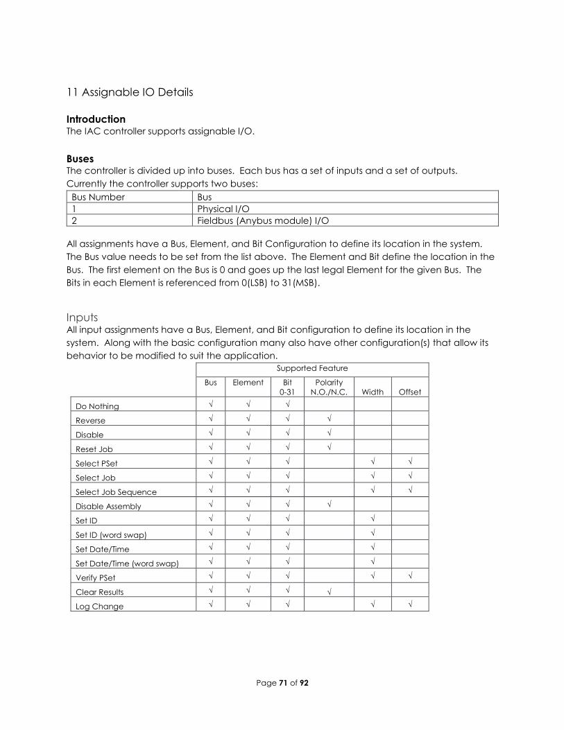
11 Assignable IO Details
Introduction The IAC controller supports assignable I/O.
Buses The controller is divided up into buses. Each bus has a set of inputs and a set of outputs.
Currently the controller supports two buses:
Bus Number Bus
1 Physical I/O
2 Fieldbus (Anybus module) I/O
All assignments have a Bus, Element, and Bit Configuration to define its location in the system.
The Bus value needs to be set from the list above. The Element and Bit define the location in the
Bus. The first element on the Bus is 0 and goes up the last legal Element for the given Bus. The
Bits in each Element is referenced from 0(LSB) to 31(MSB).
Inputs All input assignments have a Bus, Element, and Bit configuration to define its location in the
system. Along with the basic configuration many also have other configuration(s) that allow its
behavior to be modified to suit the application.
Supported Feature
Bus Element Bit
0-31
Polarity
N.O./N.C. Width Offset
Do Nothing √ √ √
Reverse √ √ √ √
Disable √ √ √ √
Reset Job √ √ √ √
Select PSet √ √ √ √ √
Select Job √ √ √ √ √
Select Job Sequence √ √ √ √ √
Disable Assembly √ √ √ √
Set ID √ √ √ √
Set ID (word swap) √ √ √ √
Set Date/Time √ √ √ √
Set Date/Time (word swap) √ √ √ √
Verify PSet √ √ √ √ √
Clear Results √ √ √ √
Log Change √ √ √ √ √
Page 72 of 92
Polarity
When the polarity is set to N.O. the input is considered active high (24vdc for physical inputs and
logic 1 for all network type Buses). When the polarity is set to N.C. the input is considered active
low (0vdc for physical inputs and logic 0 for all network type Buses).
Width and Offset
For multiple Bit inputs (for example “Select PSet”) the width variable defines the number of Bits
the assignment will read for its input. This allows the input size to be restricted to a few Bits saving
space for other assignments.
The offset variable allows a fixed value to be added to the read value.
For example, to use Bits 4 & 5 of the physical inputs to select parameter sets 1-4 the assignment
would look like:
Select PSet
Bus 1 For the physical bus
Element 0 For the first element on the bus
Bit 4 For the starting bit location
Bits 2 To span the two bits 4 & 5
Start at 1 Adding 1 to the read input value so we get…
Binary 00 = 1
Binary 01 = 2
Binary 10 = 3
Binary 11 = 4
Assignments
Do Nothing
Supported Feature
Bus Element Bit
0-31
Polarity
N.O./N.C. Width Offset
√ √ √
The “Do Nothing” assignment will run do nothing if it is active or inactive.
Stop
Supported Feature
Bus Element Bit
0-31
Polarity
N.O./N.C. Width Offset
√ √ √ √
The “Stop” assignment will stop the tool if it is running and prevent it from being started.
Disable
Supported Feature
Bus Element Bit
0-31
Polarity
N.O./N.C. Width Offset
√ √ √ √
The “Disable” will disable the tool while the input is active. It will not stop a fastening cycle that is
progress.
Page 73 of 92
Reset Job
Supported Feature
Bus Element Bit
0-31
Polarity
N.O./N.C. Width Offset
√ √ √ √
On the transition of inactive to active the “Reset Job” assignment will reset the active Job.
Select PSet
Supported Feature
Bus Element Bit
0-31
Polarity
N.O./N.C. Width Offset
√ √ √ √ √
The “Select PSET” input will select the parameter set according to the input value. Uses the
width parameter limit the width of the input bits read. The minimum width is 1 and the maximum
is 8. After the input is read the offset parameter will be added to the value do get the actual
parameter set number. Selecting an invalid parameter set number will disable the tool.
Select Job
Supported Feature
Bus Element Bit
0-31
Polarity
N.O./N.C. Width Offset
√ √ √ √ √
The “Select Job” input will select the job number according to the input value. Uses the width
parameter limit the width of the input bits read. The minimum width is 1 and the maximum is 8.
After the input is read the offset parameter will be added to the value do get the actual job
number. Selecting an invalid job number will disable the tool.
Select Job Sequence
Supported Feature
Bus Element Bit
0-31
Polarity
N.O./N.C. Width Offset
√ √ √ √ √
The “Select Job Sequence” input will select the job sequence number according to the input
value. Uses the width parameter limit the width of the input bits read. The minimum width is 1
and the maximum is 8. After the input is read the offset parameter will be added to the value
do get the actual job sequence number. Selecting an invalid job sequence number or a
sequence that is already complete will disable the tool.
Disable Assembly
Supported Feature
Bus Element Bit
0-31
Polarity
N.O./N.C. Width Offset
√ √ √ √
The “Disable Assembly” assignment will disable the tool in the assembly direction. It will not
disable the tool in disassembly or tube nut homing. It will not stop a fastening cycle that is
progress.
Set ID
Supported Feature
Bus Element Bit
0-31
Polarity
N.O./N.C. Width Offset
√ √ √ √
Page 74 of 92
The “Set ID” assignment will set the ID to an integer value of the input value. The width can be
set from 1 to 32 bits. The input value will read as an integer value and an ASCII string with
leading zeroes will be produced and passed to the ID recognition system. The length of the
string is based on the width of the assignment. The string will always be sized to accommodate
the maximum value of the input. For example, a width setting of 16 can have an integer value of
0-65535 so the produced ID would be “00000” to “65535” (always five character long).
Width setting Length of ID string ID value
1 - 3 1 “0” – “n”
4 - 6 2 “00” – “nn”
7 - 9 3 “000“ – “nnn”
10 - 13 4 “0000” – “nnnn”
14 - 16 5 “00000” – “nnnnn”
17 – 19 6 “000000” – “nnnnnn”
20 – 23 7 “0000000” – “nnnnnnn”
24 – 26 8 “00000000” – “nnnnnnnn”
27 – 29 9 “000000000” – “nnnnnnnnn”
30 - 32 10 “0000000000” – “nnnnnnnnnn”
Set ID (word swap)
Supported Feature
Bus Element Bit
0-31
Polarity
N.O./N.C. Width Offset
√ √ √ √
The “Set ID (word swap)” assignment is the same as the “Set ID” assignment except the high and
low words (16 bit) are swapped prior to evaluation. This is to correct the mixed endianness of
some PLC. See the “Set ID” for behavior.
Set Date/Time
Supported Feature
Bus Element Bit
0-31
Polarity
N.O./N.C. Width Offset
√ √ √ √
The “Set Date/Time” assignment will set the date and time of the controller. The width can be
set from 1 to 32 bits but should always be set to 32 bits to get the correct results. The input value
will be read as the number of seconds since 00:00:00 January 1, 1970 (POSIX time or Epoch time).
If the input value changes and it is non-zero the date and time of the controller will be set to the
new value.
Set Date/Time (word swap)
Supported Feature
Bus Element Bit
0-31
Polarity
N.O./N.C. Width Offset
√ √ √ √
The “Set Date/Time (word swap)” assignment is the same as the “Set Date/Time” assignment
except the high and low words (16 bit) are swapped prior to evaluation. This is to correct the
mixed endianness of some PLC. See the “Set Date/Time” for behavior.
Verify PSet
Supported Feature
Bus Element Bit
0-31
Polarity
N.O./N.C. Width Offset
Page 75 of 92
√ √ √ √ √
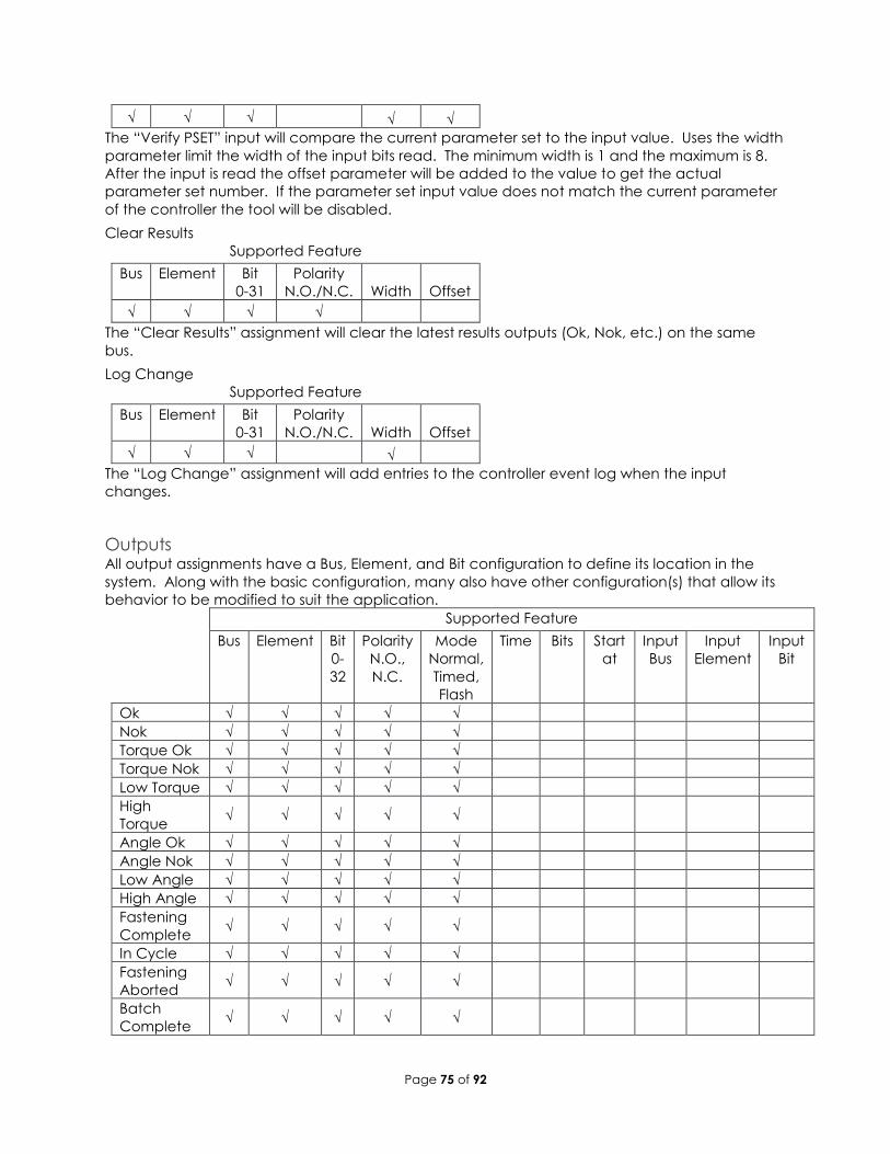
The “Verify PSET” input will compare the current parameter set to the input value. Uses the width
parameter limit the width of the input bits read. The minimum width is 1 and the maximum is 8.
After the input is read the offset parameter will be added to the value to get the actual
parameter set number. If the parameter set input value does not match the current parameter
of the controller the tool will be disabled.
Clear Results
Supported Feature
Bus Element Bit
0-31
Polarity
N.O./N.C. Width Offset
√ √ √ √
The “Clear Results” assignment will clear the latest results outputs (Ok, Nok, etc.) on the same
bus.
Log Change
Supported Feature
Bus Element Bit
0-31
Polarity
N.O./N.C. Width Offset
√ √ √ √
The “Log Change” assignment will add entries to the controller event log when the input
changes.
Outputs All output assignments have a Bus, Element, and Bit configuration to define its location in the
system. Along with the basic configuration, many also have other configuration(s) that allow its
behavior to be modified to suit the application.
Supported Feature
Bus Element Bit
0-
32
Polarity
N.O.,
N.C.
Mode
Normal,
Timed,
Flash
Time Bits Start
at
Input
Bus
Input
Element
Input
Bit
Ok √ √ √ √ √
Nok √ √ √ √ √
Torque Ok √ √ √ √ √
Torque Nok √ √ √ √ √
Low Torque √ √ √ √ √
High
Torque √ √ √ √ √
Angle Ok √ √ √ √ √
Angle Nok √ √ √ √ √
Low Angle √ √ √ √ √
High Angle √ √ √ √ √
Fastening
Complete √ √ √ √ √
In Cycle √ √ √ √ √
Fastening
Aborted √ √ √ √ √
Batch
Complete √ √ √ √ √
Page 76 of 92
Job
Complete √ √ √ √ √
Error √ √ √ √ √
Tool
Enabled √ √ √ √ √
Service
Indicator √ √ √ √ √
ToolsNet
Connected √ √ √ √ √
Open
Protocol
Connected
√ √ √ √ √
PFCS
Connected √ √ √ √ √
Running
PSet
Number
√ √ √
√ √
Running
Job
Number
√ √ √
√ √
External
Controlled √ √ √
√ √ √
Torque √ √ √ √
Torque
(x10) √ √ √
√
Torque
(x100) √ √ √
√
Angle √ √ √ √
Pulse OK √ √ √ √ √
Pulse NOK √ √ √ √ √
Low Pulse √ √ √ √ √
High Pulse √ √ √ √ √
Pulses √ √ √ √
Mode
Normal
In the “Normal” mode, the output will track the state of the assignment (while still observing the
polarity setting). If the polarity is set to N.O. and the assignment has an active output, the output
will be on and stay on until the assignment goes to inactive.
Page 77 of 92
Figure 1 Normal Mode
Timed
In the “Timed” mode, the output will come on when the assignments state goes active and go
off based on the time value or the assignment state going inactive (while still observing the
polarity setting).
Figure 2 Timed Mode (assignment deactivates before time expires)
Flash
In the “flash” mode the output will flash at the time rate while the assignments state is active (still
observing the polarity setting).
Assignments active state
Output state
Assignments active state
Output
state Time
Time
Assignments active state
Output state
Page 78 of 92
Figure 3 Flash Mode
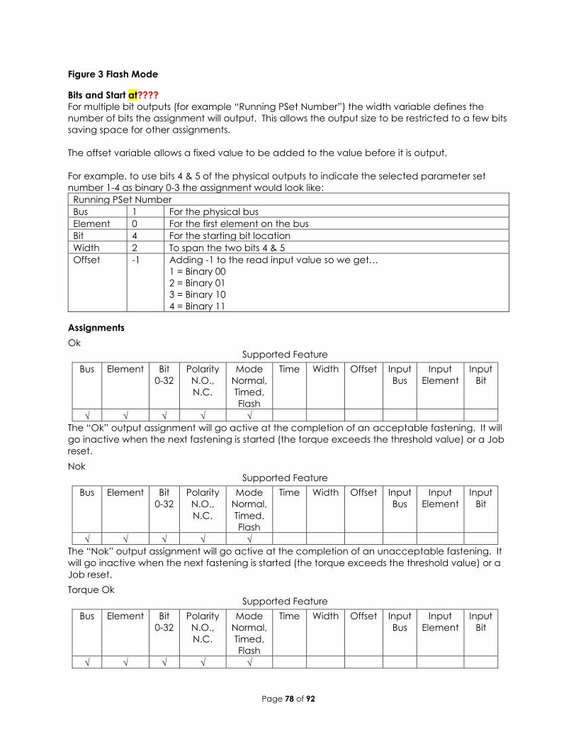
Bits and Start at????
For multiple bit outputs (for example “Running PSet Number”) the width variable defines the
number of bits the assignment will output. This allows the output size to be restricted to a few bits
saving space for other assignments.
The offset variable allows a fixed value to be added to the value before it is output.
For example, to use bits 4 & 5 of the physical outputs to indicate the selected parameter set
number 1-4 as binary 0-3 the assignment would look like:
Running PSet Number
Bus 1 For the physical bus
Element 0 For the first element on the bus
Bit 4 For the starting bit location
Width 2 To span the two bits 4 & 5
Offset -1 Adding -1 to the read input value so we get…
1 = Binary 00
2 = Binary 01
3 = Binary 10
4 = Binary 11
Assignments
Ok
Supported Feature
Bus Element Bit
0-32
Polarity
N.O.,
N.C.
Mode
Normal,
Timed,
Flash
Time Width Offset Input
Bus
Input
Element
Input
Bit
√ √ √ √ √
The “Ok” output assignment will go active at the completion of an acceptable fastening. It will
go inactive when the next fastening is started (the torque exceeds the threshold value) or a Job
reset.
Nok
Supported Feature
Bus Element Bit
0-32
Polarity
N.O.,
N.C.
Mode
Normal,
Timed,
Flash
Time Width Offset Input
Bus
Input
Element
Input
Bit
√ √ √ √ √
The “Nok” output assignment will go active at the completion of an unacceptable fastening. It
will go inactive when the next fastening is started (the torque exceeds the threshold value) or a
Job reset.
Torque Ok
Supported Feature
Bus Element Bit
0-32
Polarity
N.O.,
N.C.
Mode
Normal,
Timed,
Flash
Time Width Offset Input
Bus
Input
Element
Input
Bit
√ √ √ √ √
Page 79 of 92
The “Torque Ok” output assignment will go active at the completion of a fastening that has an
acceptable torque value. It will go inactive when the next fastening is started (the torque
exceeds the threshold value) or a Job reset.
Torque Nok
Supported Feature
Bus Element Bit
0-32
Polarity
N.O.,
N.C.
Mode
Normal,
Timed,
Flash
Time Width Offset Input
Bus
Input
Element
Input
Bit
√ √ √ √ √
The “Torque Nok” output assignment will go active at the completion of a fastening that has an
unacceptable torque value. It will go inactive when the next fastening is started (the torque
exceeds the threshold value) or a Job reset.
Low Torque
Supported Feature
Bus Element Bit
0-32
Polarity
N.O.,
N.C.
Mode
Normal,
Timed,
Flash
Time Width Offset Input
Bus
Input
Element
Input
Bit
√ √ √ √ √
The “Low Torque” output assignment will go active at the completion of a fastening that has a
low torque result. It will go inactive when the next fastening is started (the torque exceeds the
threshold value) or a Job reset.
High Torque
Supported Feature
Bus Element Bit
0-32
Polarity
N.O.,
N.C.
Mode
Normal,
Timed,
Flash
Time Width Offset Input
Bus
Input
Element
Input
Bit
√ √ √ √ √
The “High Torque” output assignment will go active at the completion of a fastening that has a
high torque result. It will go inactive when the next fastening is started (the torque exceeds the
threshold value) or a Job reset.
Angle Ok
Supported Feature
Bus Element Bit
0-32
Polarity
N.O.,
N.C.
Mode
Normal,
Timed,
Flash
Time Width Offset Input
Bus
Input
Element
Input
Bit
√ √ √ √ √
The “Angle Ok” output assignment will go active at the completion of a fastening that has an
acceptable angle result. It will go inactive when the next fastening is started (the torque
exceeds the threshold value) or a Job reset.
Angle Nok
Supported Feature
Bus Element Bit
0-32
Polarity
N.O.,
N.C.
Mode
Normal,
Timed,
Flash
Time Width Offset Input
Bus
Input
Element
Input
Bit
Page 80 of 92
√ √ √ √ √
The “Angle Nok” output assignment will go active at the completion of a fastening that has an
unacceptable angle result. It will go inactive when the next fastening is started (the torque
exceeds the threshold value) or a Job reset.
Low Angle
Supported Feature
Bus Element Bit
0-32
Polarity
N.O.,
N.C.
Mode
Normal,
Timed,
Flash
Time Width Offset Input
Bus
Input
Element
Input
Bit
√ √ √ √ √
The “Low Angle” output assignment will go active at the completion of a fastening that has a
low angle result. It will go inactive when the next fastening is started (the torque exceeds the
threshold value) or a Job reset.
High Angle
Supported Feature
Bus Element Bit
0-32
Polarity
N.O.,
N.C.
Mode
Normal,
Timed,
Flash
Time Width Offset Input
Bus
Input
Element
Input
Bit
√ √ √ √ √
The “High Angle” output assignment will go active at the completion of a fastening that has a
high angle result. It will go inactive when the next fastening is started (the torque exceeds the
threshold value) or a Job reset.
Fastening Complete
Supported Feature
Bus Element Bit
0-32
Polarity
N.O.,
N.C.
Mode
Normal,
Timed,
Flash
Time Width Offset Input
Bus
Input
Element
Input
Bit
√ √ √ √ √
The “Fastening Complete” output assignment will go active at the completion of a fastening. It
will go inactive when the next fastening is started (the torque exceeds the threshold value) or a
Job reset.
In Cycle
Supported Feature
Bus Element Bit
0-32
Polarity
N.O.,
N.C.
Mode
Normal,
Timed,
Flash
Time Width Offset Input
Bus
Input
Element
Input
Bit
√ √ √ √ √
The “In Cycle” output assignment will go active at the start of the fastening cycle (the torque
exceeds the threshold value). It will go inactive when the fastening cycle ends.
Fastening Aborted
Supported Feature
Bus Element Bit
0-32
Polarity
N.O.,
N.C.
Mode
Normal,
Timed,
Flash
Time Width Offset Input
Bus
Input
Element
Input
Bit
Page 81 of 92
√ √ √ √ √
The “Fastening Aborted” output assignment will go active at the completion of a fastening that
was aborted by the system. It will go inactive when the next fastening is started (the torque
exceeds the threshold value) or a Job reset.
Batch Complete
Supported Feature
Bus Element Bit
0-32
Polarity
N.O.,
N.C.
Mode
Normal,
Timed,
Flash
Time Width Offset Input
Bus
Input
Element
Input
Bit
√ √ √ √ √
The “Batch Complete” output assignment will go active at the completion of a fastening that
satisfies the bolt count of a Job sequence. It will go inactive when the next fastening is started
(the torque exceeds the threshold value) or the job is reset.
Job Complete
Supported Feature
Bus Element Bit
0-32
Polarity
N.O.,
N.C.
Mode
Normal,
Timed,
Flash
Time Width Offset Input
Bus
Input
Element
Input
Bit
√ √ √ √ √
The “Job Complete” output assignment will go active at the completion of a fastening that
satisfies all the sequences. It will go inactive when the next fastening is started (the torque
exceeds the threshold value) or the job is reset.
Error
Supported Feature
Bus Element Bit
0-32
Polarity
N.O.,
N.C.
Mode
Normal,
Timed,
Flash
Time Width Offset Input
Bus
Input
Element
Input
Bit
√ √ √ √ √
The “Error” output assignment will be active while the controller has an error.
Tool Enabled
Supported Feature
Bus Element Bit
0-32
Polarity
N.O.,
N.C.
Mode
Normal,
Timed,
Flash
Time Width Offset Input
Bus
Input
Element
Input
Bit
√ √ √ √ √
The “Tool Enabled” output assignment will be active if the tool is enabled.
Tool Running
Supported Feature
Bus Element Bit
0-32
Polarity
N.O.,
N.C.
Mode
Normal,
Timed,
Flash
Time Width Offset Input
Bus
Input
Element
Input
Bit
√ √ √ √ √
The “Tool Running” output assignment will be active while the tool is running.
Page 82 of 92
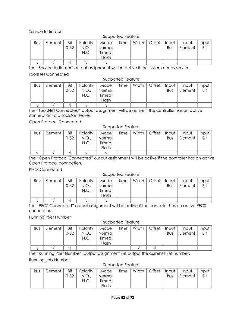
Service Indicator
Supported Feature
Bus Element Bit
0-32
Polarity
N.O.,
N.C.
Mode
Normal,
Timed,
Flash
Time Width Offset Input
Bus
Input
Element
Input
Bit
√ √ √ √ √
The “Service Indicator” output assignment will be active if the system needs service.
ToolsNet Connected
Supported Feature
Bus Element Bit
0-32
Polarity
N.O.,
N.C.
Mode
Normal,
Timed,
Flash
Time Width Offset Input
Bus
Input
Element
Input
Bit
√ √ √ √ √
The “ToolsNet Connected” output assignment will be active if the controller has an active
connection to a ToolsNet server.
Open Protocol Connected
Supported Feature
Bus Element Bit
0-32
Polarity
N.O.,
N.C.
Mode
Normal,
Timed,
Flash
Time Width Offset Input
Bus
Input
Element
Input
Bit
√ √ √ √ √
The “Open Protocol Connected” output assignment will be active if the controller has an active
Open Protocol connection.
PFCS Connected
Supported Feature
Bus Element Bit
0-32
Polarity
N.O.,
N.C.
Mode
Normal,
Timed,
Flash
Time Width Offset Input
Bus
Input
Element
Input
Bit
√ √ √ √ √
The “PFCS Connected” output assignment will be active if the controller has an active PFCS
connection.
Running PSet Number
Supported Feature
Bus Element Bit
0-32
Polarity
N.O.,
N.C.
Mode
Normal,
Timed,
Flash
Time Width Offset Input
Bus
Input
Element
Input
Bit
√ √ √ √ √
The “Running PSet Number” output assignment will output the current PSet number.
Running Job Number
Supported Feature
Bus Element Bit
0-32
Polarity
N.O.,
N.C.
Mode
Normal,
Timed,
Flash
Time Width Offset Input
Bus
Input
Element
Input
Bit
Page 83 of 92
√ √ √ √ √
The “Running Job Number” output assignment will output the current Job number.
External Controlled
Supported Feature
Bus Element Bit
0-32
Polarity
N.O.,
N.C.
Mode
Normal,
Timed,
Flash
Time Width Offset Input
Bus
Input
Element
Input
Bit
√ √ √ √ √ √
The “External Controlled” output assignment will reflect the state of an input. Use the “Input Bus”
“Input Element” and “Input Bit” to specify the input to reflect.
Torque
Supported Feature
Bus Element Bit
0-32
Polarity
N.O.,
N.C.
Mode
Normal,
Timed,
Flash
Time Width Offset Input
Bus
Input
Element
Input
Bit
√ √ √ √
The “Torque” output assignment will output the final torque value of the most recent rundown.
The value will be cleared to 0 at the start of a new fastening cycle or a Job reset. At the end of
the fastening cycle the final torque will be truncated to an integer and output.
Torque (x10)
Supported Feature
Bus Element Bit
0-32
Polarity
N.O.,
N.C.
Mode
Normal,
Timed,
Flash
Time Width Offset Input
Bus
Input
Element
Input
Bit
√ √ √ √
The “Torque (x10)” output assignment will output the final torque value of the most recent
rundown. The value will be cleared to 0 at the start of a new fastening cycle or a Job reset. At
the end of the fastening cycle, the final torque will be multiplied by 10, truncated to an integer
and output.
Torque (x100)
Supported Feature
Bus Element Bit
0-32
Polarity
N.O.,
N.C.
Mode
Normal,
Timed,
Flash
Time Width Offset Input
Bus
Input
Element
Input
Bit
√ √ √ √
The “Torque (x100)” output assignment will output the final torque value of the most recent
rundown. The value will be cleared to 0 at the start of a new fastening cycle or a Job reset. At
the end of the fastening cycle, the final torque will be multiplied by 100, truncated to an integer
and output.
Angle
Supported Feature
Bus Element Bit
0-32
Polarity
N.O.,
N.C.
Mode
Normal,
Timed,
Flash
Time Width Offset Input
Bus
Input
Element
Input
Bit
Page 84 of 92
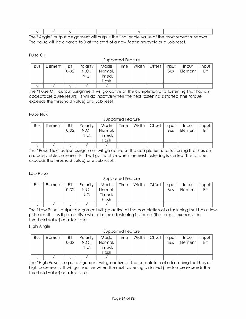
√ √ √ √
The “Angle” output assignment will output the final angle value of the most recent rundown.
The value will be cleared to 0 at the start of a new fastening cycle or a Job reset.
Pulse Ok
Supported Feature
Bus Element Bit
0-32
Polarity
N.O.,
N.C.
Mode
Normal,
Timed,
Flash
Time Width Offset Input
Bus
Input
Element
Input
Bit
√ √ √ √ √
The “Pulse Ok” output assignment will go active at the completion of a fastening that has an
acceptable pulse results. It will go inactive when the next fastening is started (the torque
exceeds the threshold value) or a Job reset.
Pulse Nok
Supported Feature
Bus Element Bit
0-32
Polarity
N.O.,
N.C.
Mode
Normal,
Timed,
Flash
Time Width Offset Input
Bus
Input
Element
Input
Bit
√ √ √ √ √
The “Pulse Nok” output assignment will go active at the completion of a fastening that has an
unacceptable pulse results. It will go inactive when the next fastening is started (the torque
exceeds the threshold value) or a Job reset.
Low Pulse
Supported Feature
Bus Element Bit
0-32
Polarity
N.O.,
N.C.
Mode
Normal,
Timed,
Flash
Time Width Offset Input
Bus
Input
Element
Input
Bit
√ √ √ √ √
The “Low Pulse” output assignment will go active at the completion of a fastening that has a low
pulse result. It will go inactive when the next fastening is started (the torque exceeds the
threshold value) or a Job reset.
High Angle
Supported Feature
Bus Element Bit
0-32
Polarity
N.O.,
N.C.
Mode
Normal,
Timed,
Flash
Time Width Offset Input
Bus
Input
Element
Input
Bit
√ √ √ √ √
The “High Pulse” output assignment will go active at the completion of a fastening that has a
high pulse result. It will go inactive when the next fastening is started (the torque exceeds the
threshold value) or a Job reset.
Page 85 of 92
12 Open Protocol Message IDs Open Protocol Supported MID
MID Description Revisions Note
1 Communication start 1,2,3
2 Communication start acknowledge 1,2,3
3 Communication stop
4 Command error
5 Command accepted
10 Parameter set ID upload request
11 Parameter set ID upload reply
14 Parameter set selected subscribe
15 Parameter set selected
16 Parameter set selected acknowledge
17 Parameter set selected unsubscribe
18 Select Parameter set
20 Reset Parameter set batch counter 30 Job ID upload request
31 Job ID upload reply
34 Job info subscribe
35 Job info
36 Job info acknowledge
37 Job info unsubscribe
38 Select Job
39 Job restart
40 Tool data upload request 1,2
41 Tool data upload reply
42 Disable tool
43 Enable tool
50 Vehicle ID number download request
51 Vehicle ID number subscribe 1,2
52 Vehicle ID number
53 Vehicle ID number acknowledge
54 Vehicle ID number unsubscribe
60 Last tightening result data subscribe 1,2,3,999
61 Last tightening result data
62 Last tightening result data acknowledge
63 Last tightening result data unsubscribe
64 Old tightening result upload request
65 Old tightening result upload reply
70 Alarm subscribe
71 Alarm
Page 86 of 92
72 Alarm acknowledge
73 Alarm unsubscribe
76 Alarm status
77 Alarm status acknowledge
80 Read time upload request
81 Read time upload reply
82 Set time
113 Flash green light on tool
127 Abort Job
130 Job off
150 Identifier download request
157 Reset all Identifiers
200 Set external controlled relays Only supports 0 (off) and 1 (on)
210 Status external monitored inputs subscribe
211 Status external monitored inputs
212 Status external monitored inputs acknowledge
213 Status external monitored inputs unsubscribe
214 IO device status request 1,2
215 IO device status reply
216 Relay function subscribe See supported relay functions below.
217 Relay function
218 Relay function acknowledge
219 Relay function unsubscribe
9999 Keep alive open protocol communication
Open Protocol Supported Relay Functions
Number Function
1 OK
2 NOK
5 Low Torque
6 High Torque
7 Low angle
8 High angle
9 Cycle complete
10 Alarm
11 Batch NxOK
12 Job OK
19 Tool ready
20 Tool start switch
21 Dir. switch = CW
22 Dir. switch = CCW
26 Tool running
276 Cycle abort
Page 87 of 92
13 Dimensions
Page 88 of 92
14 Specifications Mechanical:
Dimensions: Width: 6.25 in 159 mm
Height: 15.75 in 400 mm
Depth: 12.5 in 316 mm
Weight: Controller: 11 – 151bs
depending on
options
5 – 6.8 kg depending
on options
Plinth 4.5lbs 2 kg
Operating Conditions:
Temperature: 32 to 122 ᵒF (0 to50 ᵒC)
Humidity: Non-condensing
Ingress Protection: IP20
Air Connections (models with internal shutoff valve and/or electronic regulator):
Supply Air Inlet: 130 PSI Maximum, Clean, Dry Air Fitting Type: ½” NPT Female
Air Outlet to Tool Fitting Type: ½” NPT Female
Exhaust Fitting Type: 3/8” NPT Female
Electrical:
AC Power Source: 100 - 240 VAC, 50/60 Hz, 1Amp, 100 Watts
Standards Compliance: Contact AIMCO for details.
Page 89 of 92
13 Trouble Shooting
SD Card The rear SD card can be used to easily move the software, firmware, configuration, and
rundowns to a new controller in the event of hardware failure. This allows the controller to be
replaced with a new unit while retaining all the rundown information and configuration
settings. Remove the rear SD card from the damaged unit and insert it into a functioning unit to
perform the replacement. It is highly recommended that the controller settings are backed up
and saved by exporting the controller to a USB flash drive.
System port IP Address NOTE: In the event the RNDIS drivers do not install themselves, the following are the steps to install
new drivers to get the system port working.
The RNDIS driver is a part of the Windows 7 operating system, but the OS fails to detect it
automatically. The following steps will help the user to install the RNDIS driver:
Step 1 After the device is connected to the development PC, OS will automatically search for
the RNDIS driver; after it fails to find the driver, the following message will be shown:
Step 2 Right click on Computer and select Manage. From System Tools, select Device Manager.
It will show a list of devices currently connected with the development PC. In the list, RNDIS Kitl
can be seen with an exclamation mark implying that driver has not been installed.
Page 90 of 92
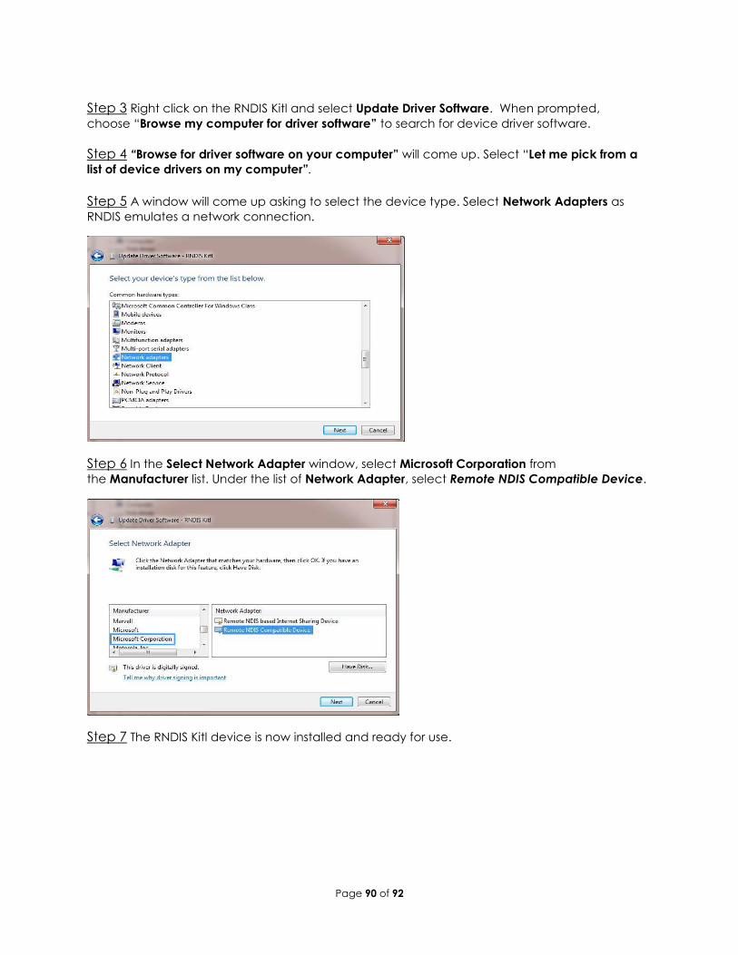
Step 3 Right click on the RNDIS Kitl and select Update Driver Software. When prompted,
choose “Browse my computer for driver software” to search for device driver software.
Step 4 “Browse for driver software on your computer” will come up. Select “Let me pick from a
list of device drivers on my computer”.
Step 5 A window will come up asking to select the device type. Select Network Adapters as
RNDIS emulates a network connection.
Step 6 In the Select Network Adapter window, select Microsoft Corporation from
the Manufacturer list. Under the list of Network Adapter, select Remote NDIS Compatible Device.
Step 7 The RNDIS Kitl device is now installed and ready for use.
Page 91 of 92
14 AIMCO Warranty
NEW TOOL AND ACCESSORY WARRANTY
Any new tool or accessory branded with the AIMCO, Uryu, AcraDyne or Eagle Group name, and
purchased from AIMCO, or through one of its authorized distributors or agents, is warranted to the
original buyer against defects in materials and workmanship for a period of one (1) year* from
date of delivery. Under the terms of this warranty, AIMCO agrees, without charge, to repair or
replace, at its option and Ex-Works (EXW) its authorized service centers, any product or accessory
warranted hereunder proving to AIMCO's satisfaction to be defective as a result of defective
workmanship or material. To qualify for this warranty, written notice to AIMCO must be given
immediately upon discovery of such defect, at which time AIMCO will issue an authorization to
return the tool. The defective item must be promptly returned to an authorized AIMCO service
center with all freight charges prepaid.
REPAIRED TOOL WARRANTY
Once a tool is beyond the new product warranty period as detailed above, AIMCO will provide
repair subject to the following warranty periods: pneumatic tools: 90 days*; electric tools and
AcraFeed: 90 days; battery tools: 30 days*; DC Electric tools: 90 days*
EXCLUSION FROM WARRANTY
This warranty is valid only on products purchased from AIMCO, or thru its authorized distributors or
agents. AIMCO shall have no obligation pursuant to the AIMCO Warranty with respect to any tools
or accessories which in AIMCO's sole judgment have been altered damaged, misused, abused,
badly worn, lost or improperly maintained. This Warranty is null and void if the customer, or any
other person other than an authorized representative of AIMCO, has made any attempt to service
or modify the tool or accessory prior to its return to AIMCO under this Warranty.
The warranty provision with respect to each such product may be amended by AIMCO from time
to time in its sole discretion. The liability of AIMCO hereunder shall be limited to replacing or
repairing, at its option, any defective products which are returned freight pre-paid to AIMCO or,
at AIMCO's option, refunding the purchase price of such products.
AIMCO reserves the right to make periodic changes in construction or tool design at any time.
AIMCO specifically reserves the right to make these changes without incurring any obligation or
incorporating such changes or updates in tools or parts previously distributed.
THE AIMCO WARRANTY IS IN LIEU OF ALL OTHER WARRANTIES, EXPRESSED OR IMPLIED, AND AIMCO
EXPRESSLY DISCLAIMS ANY WARRANTY OF MERCHANTABILITY OR FITNESS FOR A PARTICULAR
PURPOSE. THIS WARRANTY SETS FORTH THE SOLE AND EXCLUSIVE REMEDY IN CONTRACT, TORT,
STRICT LIABILITY, OR OTHERWISE.
THIS WARRANTY IS THE ONLY WARRANTY MADE BY AIMCO WITH RESPECT TO THE GOODS DELIVERED
HEREUNDER, AND MAY BE MODIFIED OR AMENDED ONLY BY A WRITTEN INSTRUMENT SIGNED BY A
DULY AUTHORIZED OFFICER OF AIMCO.
LIMITATION OF LIABILITY
AIMCO'S LIABILITY PURSUANT TO WARRANTY OF THE PRODUCTS COVERED HEREUNDER IS LIMITED TO
REFUND OF THE PURCHASE PRICE. IN NO EVENT SHALL AIMCO BE LIABLE FOR COSTS OF
PROCUREMENT OF SUBSTITUTE GOODS BY THE BUYER. IN NO EVENT SHALL AIMCO BE LIABLE FOR
ANY SPECIAL, CONSEQUENTIAL, INCIDENTAL OR OTHER DAMAGES (INCLUDING WITHOUT
LIMITATION, LOSS OF PROFIT) WHETHER OR NOT AIMCO HAS BEEN ADVISED OF THE POSSIBILITY OF
SUCH LOSS, HOWEVER CAUSED, WHETHER FOR BREACH OR REPUDIATION OF CONTRACT, BREACH
Page 92 of 92
OF WARRANTY, NEGLIGENCE OR OTHERWISE. THIS EXCLUSION ALSO INCLUDES ANY LIABILITY
WHICH MAY ARISE OUT OF THIRD PARTY CLAIMS AGAINST BUYER. THE ESSENTIAL PURPOSE OF THIS
PROVISION IS TO LIMIT THE POTENTIAL LIABILITY OF AIMCO ARISING OUT OF THIS AGREEMENT
AND/OR SALE.
NOTE: The AIMCO Warranty confers specific legal rights, however some states or jurisdictions may
not allow certain exclusions or limitations within this warranty. *Note – All warranty periods
addressed herein are determined using a standard shift, eight-hour work day.