29
IMPROVE THE EFFICIENCY OF HEAT EXCHANGER IN OIL COOLER. PARMAR NAVIN J (D11ME09) PRAJAPATI JAIMIN R (10ME41) PATEL DEEP K (10ME56) INTERNAL GUIDE:- DIXIT M PATEL

IMPROVE THE EFFICIENCY OF HEAT EXCHANGER IN OIL COOLER.
PARMAR NAVIN J (D11ME09)
PRAJAPATI JAIMIN R (10ME41)
PATEL DEEP K (10ME56)
INTERNAL GUIDE:- DIXIT M PATEL

ABSTRACT
For shell-and-tube oil cooler with water cooling, the heat transferresistance on the shell side is 80% of the total heat transferresistance of the cooler ,so oil heat transfer resistance is controlling.It is a key factor to increase heat transfer coefficient of oil on theshell side for making high performance oil cooler. Two measures tobe taken to increase heat transfer coefficient of oil, are first to usehighly effective enhanced tube ,and second to use novel shell sidebaffle geometry or flow rate of fluid.
INTRODUCTION A heat exchanger is A device that is used to transfer thermal energy
(enthalpy) between two or more fluids, between A solid surface and Afluid, or between solid particulates and A fluid, at differenttemperatures and in thermal contact. In heat exchangers, there areusually no external heat and work interactions. Typical applicationsinvolve heating or cooling of A fluid stream of concern andevaporation or condensation of single- or multi component fluidstreams.
In A few heat exchangers, the fluids exchanging heat are in directcontact. In most heat exchangers, heat transfer between fluids takesplace through A separating wall or into and out of A wall in A transientmanner.
SCOPE OF PROJECT
4
Heat exchanger used for heat transfer take place for cooling or
heating purpose. Shell and tube type heat exchanger is mostly found
in industrial application.
Heat exchange between two substance is always depend upon
medium surrounding it and also its part’s dimensions.
Shell and tube type heat exchanger manufacture based on its design
and its operating conditions like injection molding machine . If
design modification as well as new accessories joint with heat
exchanger, give better performance as well as give better heat
transfer. Project aim that improve performance and heat transfer
coefficient by using buffels for increase area of heat transfer and also
applied different material tube with different diameter of tube for
analyze profomance of heat exchanger

Methodology
5
Project selection
Concept develop
Selection of working procedure
Selection of working area
[Design]
Implementation
Result
End

TYPE OF HEAT EXCHANGER Shell And Tube Heat Exchanger
Plate Heat Exchanger
Plate And Shell Heat Exchanger
Adiabatic Wheel Heat Exchanger
Plate Fin Heat Exchanger
Pillow Plate Heat Exchanger
Fluid Heat Exchangers
Waste Heat Recovery Units
Dynamic Scraped Surface Heat Exchanger
Phase-change Heat Exchangers
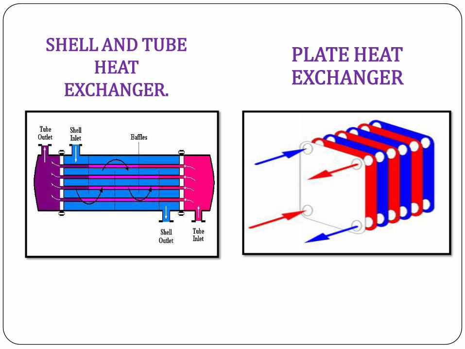
SHELL AND TUBE HEAT
EXCHANGER.
PLATE HEAT EXCHANGER
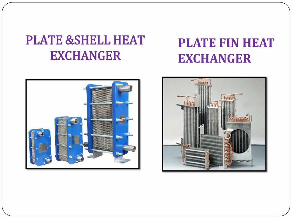
PLATE &SHELL HEAT EXCHANGER
PLATE FIN HEAT EXCHANGER

WASTE HEAT RECOVERY UNITS

LITERATURE SURVEY
[1] CFD AND EXPERIMENTAL STUDIES ON HEAT TRANSFER ENHANCEMENT IN ANAIR COOLER EQUIPPED WITH DIFFERENT TUBE INSERTS.
Author: S.R. Shabanian , M. Rahimi M. Shahhosseini , A.A. Alsairafi
Journal: Science Direct
Work:
This paper reports the experimental and Computational Fluid Dynamics (CFD) modelingstudies on heat transfer, friction factor and thermal performance of an air cooled heatexchanger equipped with three types of tube insert including butterfly, classic and jaggedtwisted tape. In the studied range of Reynolds number the maximum thermal performancefactor was obtained by the butterfly insert with an inclined angle of 90°. The results have alsorevealed that the difference between the heat transfer rates obtained from employing theclassic and jagged inserts reduces by decreasing the twist ratio. The CFD predicted results wereused to explain the observed results in terms of turbulence intensity. In addition, goodagreements between the predicted and measured Nu number as well as friction factor valueswere obtained.
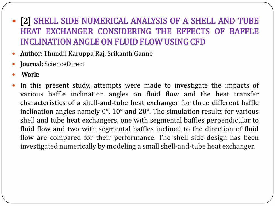
[2] SHELL SIDE NUMERICAL ANALYSIS OF A SHELL AND TUBEHEAT EXCHANGER CONSIDERING THE EFFECTS OF BAFFLEINCLINATION ANGLE ON FLUID FLOW USING CFD
Author: Thundil Karuppa Raj, Srikanth Ganne
Journal: ScienceDirect
Work:
In this present study, attempts were made to investigate the impacts ofvarious baffle inclination angles on fluid flow and the heat transfercharacteristics of a shell-and-tube heat exchanger for three different baffleinclination angles namely 0°, 10° and 20°. The simulation results for variousshell and tube heat exchangers, one with segmental baffles perpendicular tofluid flow and two with segmental baffles inclined to the direction of fluidflow are compared for their performance. The shell side design has beeninvestigated numerically by modeling a small shell-and-tube heat exchanger.

[3] MODELLING AND OPTIMIZATION OF HEAT TRANSFER IN SMOOTH CIRCULAR TUBE USED IN THE SHELL AND TUBE
ABSTRACTAn optimization of heat transfer for smooth circular tube used in the
ammonia-water absorption cooling system has been carried out to estimateminimum outlet water temperature and maximum heat flux. The tube diameterranges from 7 to 13 mm and length ranges from 0.5 to 1.2 M, has been varied tostudy the effects. The numerical analysis was performed by using the finiteelements commercial code. The optimization result has shown that 7 mmdiameter and 1.2 M length has given the minimum water temperature of 8.3 ‘c atthe outlet with maximum heat flux of 16193 W/M2.
CONCLUSION Numerical analysis and optimization of heat and fluid flow for circular smooth
tube has been investigated. As well, the effects of tube diameters and lengthswere studied. Results demonstrated that the maximum heat flux occurs withinthe smallest tube diameter and shortest length at constant wall temperature andflow rate. The temperature outlet from the tube has been presented, and thelowest value founded within the smallest tube diameter 7 mm and the longestlength of the tube 1.2 m. The present study can be reported to monitor andevaluate the performance of difference kinds of shell and tube and to optimizethe design by using the benefit of optimum heat flux from the individual pipe'swall.
Reference:- RANJ SIRWAN 1, YUSOFF ALI 1, LIM CHIN HAW2, SOHIF MAT2, A.ZAHARIM2 and K. SOPIAN 2 1Department of Mechanical andMaterials Engineering 2 Solar Energy Research Institute Faculty of Engineering, Universiti Kebangsaan Malaysia 43600 Bangi, SelangorMALAYSIA.
PROBLEM STATEMENT
In modern day shell and tube heat exchanger is widely used inindustries as a chillers plant for transfer waste heat from the injectionmolding machine to the cooling water for improve the efficiency of theinjection molding machine. The transformations of the waste heat frominjection molding machine to the cooling water is dependent on theheat exchange capacity of heat exchangers. So in now a day theindustries are facing the problem for improving the heat exchangecapacity of the heat exchanger by improving the heat exchanger’sefficiency for increase production capacity and efficiency of injectionmolding machine. For shell-and-tube oil cooler with water cooling, theheat transfer resistance on the shell side is 80% of the total heattransfer resistance of the cooler ,so oil heat transfer resistance iscontrolling .it is a key factor to increase heat transfer coefficient of oilon the shell side for making high performance oil cooler. Two measuresto be taken to increase heat transfer coefficient of oil, are first to usehighly effective enhanced tube ,and second to use novel shell side bafflegeometry.
OBJECTIVES
From problem statement the objective of work is to increase theefficiency of the shell and tube heat exchanger. The efficiency of the heatexchanger is basically depends on the geometric parameters tubediameter as well as process parameters (mass flow rate, inlet and outlettemperature of the cooling water etc.) of heat exchangers. So theobjective is to optimize some of these parameters tube diameter and flowrate for improve the efficiency of the heat exchanger.
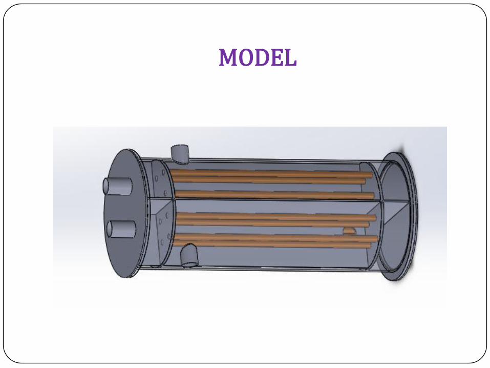
MODEL

CUT SECTION OF SHELL AND PIPE

CUT SECTION OF ½ SHELL

COUNTER FLOW
(CHANGING FLOW RATE OF HOT FLUID)
Flow Rate
Lts Per S
Cold Inlet
Temperature
Cold Outlet
Temperature
0.0833 23 32
0.1666 23 29
0.2500 23 28
0.3333 23 27
PARALLEL FLOW
(CHANGING FLOW RATE OF HOT FLUID)
Flow Rate
Lts Per S
Cold Inlet
Temperature
Cold Outlet
Temperature
0.0833 23 35
0.1666 23 33
0.2500 23 30
0.3333 23 28
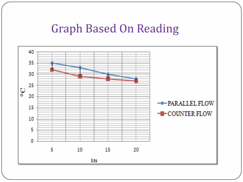
Graph Based On Reading
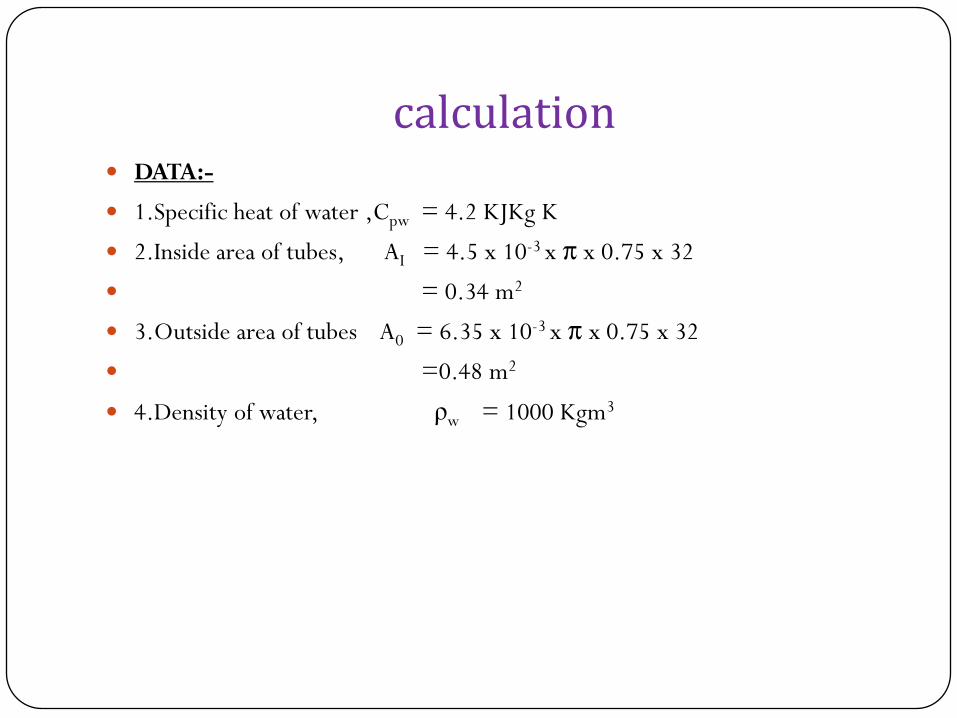
calculation DATA:-
1.Specific heat of water ,Cpw = 4.2 KJKg K
2.Inside area of tubes, AI = 4.5 x 10⁻³ x π x 0.75 x 32
= 0.34 m2
3.Outside area of tubes A0 = 6.35 x 10⁻³ x π x 0.75 x 32
=0.48 m2
4.Density of water, ρw = 1000 Kgm3
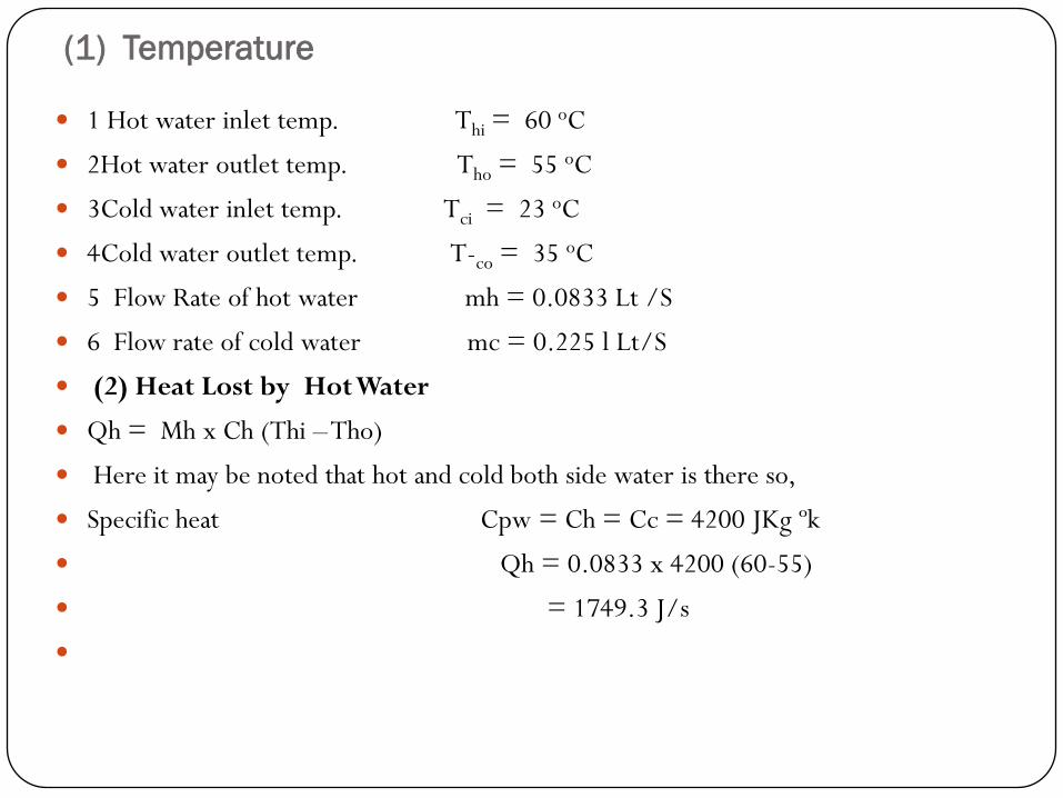
(1) Temperature
1 Hot water inlet temp. Thi = 60 oC
2Hot water outlet temp. Tho = 55 oC
3Cold water inlet temp. Tci = 23 oC
4Cold water outlet temp. Tco = 35 oC
5 Flow Rate of hot water mh = 0.0833 Lt /S
6 Flow rate of cold water mc = 0.225 l Lt/S
(2) Heat Lost by Hot Water
Qh = Mh x Ch (Thi –Tho)
Here it may be noted that hot and cold both side water is there so,
Specific heat Cpw = Ch = Cc = 4200 JKg ºk
Qh = 0.0833 x 4200 (60-55)
= 1749.3 J/s

(3) Heat Collected by Cold Water
Qc = Mc x Cc(Tco –Tci)
Here it may be noted that hot and cold both side water is there so,
Specific heat Cpw = Ch = Cc = 4200 JKg ºk
Qc = 0.225 x 4200 (35-23)
Qc = 7560 J/s
(4) Specific Heat Capacities of hot and cold water
Specific heat Capacity of Hot fluid Ch = Mh x Ch
= 0.0833 x 4200
= 349.86 Wºk
Specific heat Capacity of Cold fluid Cc = Mc x Cc
= 0.225x 4200
= 945 W/ ºk
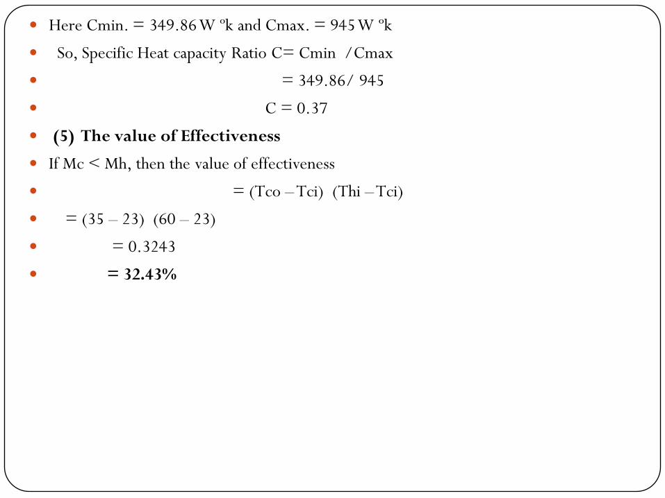
Here Cmin. = 349.86 W ºk and Cmax. = 945 W ºk
So, Specific Heat capacity Ratio C= Cmin /Cmax
= 349.86/ 945
C = 0.37
(5) The value of Effectiveness
If Mc < Mh, then the value of effectiveness
= (Tco – Tci) (Thi –Tci)
= (35 – 23) (60 – 23)
= 0.3243
= 32.43%

COPPER FOR TUBE MATERIALCOPPER
Advantages – Copper Is A Good Conductor, Malleable And Ductile So Make It Good For Bending Copper Pipes
Into Shapes. It Has Very Durable.
Disadvantages – The Only Real Disadvantage Of Copper Is It Is Expensive To Buy. Alloys Don't Have The Strengths Levels Of Steel Alloys.

CALCULATION OF PERFORMANCE OF CROSS COUNTER FLOW HEAT EXCHANGER BY CHANGING THE VARIOUS PARAMETERS
By Increasing The Cold Fluid Flow Rate By 10% To 90%
By Decreasing The Cold Fluid Flow Rate By 10% To 90%
By Changing The Direction Of Fluid Flow (Parallel Instead On Counter Flow)
By Increasing The Hot Fluid Flow Rate By 10% To 90%
By Decreasing The Hot Fluid Flow Rate By 10% To 90%
By Changing The Pressure Drop.
By Decreasing The Tube Diameter
CONCLUSION
27
From expriment and research paper and conclude that if tube diameter of tube as well as material of tube changes then, may be increase effectiveness of heat exchanger.
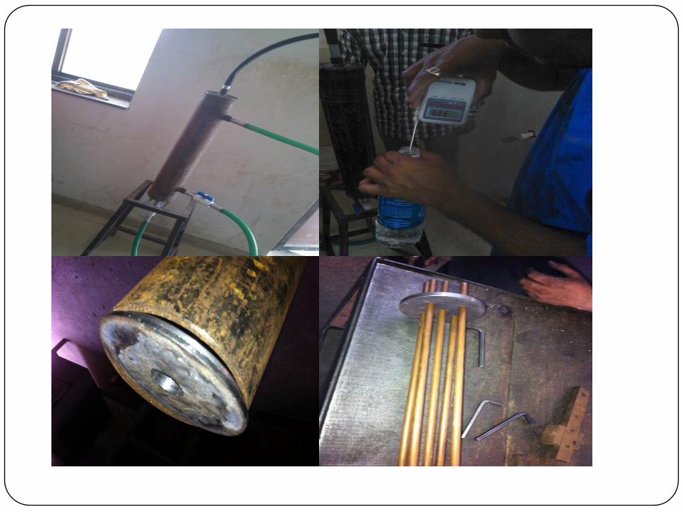
Baffles serve two important functions. They support the tubes during assembly and operation and help prevent vibration from flow induced eddies and direct the shell side fluid back and forth across the tube bundle to provide effective velocity and Heat Transfer rates.
If no of baffles are attach to heat exchanger give better effectiveness of heat exchanger.
If material as well as dimensions of tube changes then it will give improvement in effectiveness of heat exchanger.
REFERENCES P. Parthasarathy, P. Talukdar, V.R. Kishore, Enhancement of heat transfer with porous/solid insert for
laminar flow of a participating gas in a 3-D square duct, Numerical Heat Transfer; Part A: Applications 56 (9) (2009) 764–784.
S. Kiwan, M.S. Alzahrany, Effect of using porous inserts on natural convection heat transfer between two concentric vertical cylinders, Numerical Heat Transfer; Part A: Applications 53 (8) (2008) 870–889.
N. Yucel, R.T. Guven, Forced-convection cooling enhancement of heated elements in a parallel-plate channels using porous inserts, Numerical Heat Transfer; Part A: Applications 51 (3) (2007) 293–312.
X. Tong, J.A. Khan, M.R. Amin, Enhancement of heat transfer by inserting a metal matrix into a phase change material, Numerical Heat Transfer; Part A: Applications 30 (2) (1996) 125–141.
R.M. Manglik, A.E. Bergles, Heat transfer and pressure drop correlations for twisted-tape inserts in isothermal tubes: part II-transition and turbulent flows, Enhanced Heat Transfer, Transaction ASME, Journal Heat Transfer 202 (1992) 99–106.
S.K. Agarwal, M. Raja Rao, Heat transfer augmentation for the flow of a viscous liquid in circular tubes using twisted tape inserts, International Journal of Heat and Mass Transfer 39 (17) (1996) 3547–3557.
C. Yildiz, Y. Bicer, D. Pehlivan, Effect of twisted strips on heat transfer and pressure drop in heat exchangers, Energy Conversion and Management 39 (3–4) (1998) 331–336.
S.K. Saha, A. Dutta, S.K. Dhal, Friction and heat transfer characteristics of laminar swirl flow through a circular tubes fitted with regularly spaced twisted-tape elements, International Journal of Heat and Mass Transfer 44 (22) (2001) 4211–4223.
www.google.com
http://en.wikipedia.org/wiki/Heat_exchanger