In two earlier papers1,2 we presented a new and effi-cient method for simulating divergent-light halos aswell as comparisons with observations of such halosin the field. In these papers we also described thedifferences and similarities between ordinaryparallel-light halos and divergent-light halos and ex-plained why it is much more difficult to simulate adivergent-light halo than a parallel-light halo, a factthat explains why almost no such simulations havebeen published. For details we refer to our previouspapers. Although the algorithm presented in thesepapers is computationally quite efficient it has draw-backs. The mathematics is somewhat involved, andthe computer program that implements the algo-rithm is lengthy and not transparent. A more seriousmatter, as pointed out by Moilanen,3 is that the al-gorithm lacks proper event weighting, which, for ex-ample, gives a wrong intensity distribution in thedivergent-light halo produced by randomly orientedice crystals.
In the present paper we present an improved algo-rithm that has a mathematically rigorous weighting
of the events. Like the previous algorithm the algo-rithm is based on spatial rotations, but, instead ofusing a restricted set of rotations, we now allow thefull set of rotations in space. The algorithm is alsomuch simpler, the computer implementation is verycompact, and the whole procedure is elegant and con-ceptually easy to understand.
2. Theory
A. Assumptions
Let the light source be located at the origin O� �0, 0, 0� and the observer at a fixed position R at adistance R from the origin. Let the cloud of ice crys-tals be characterized by a homogeneous number den-sity n and a fixed distribution Q�U� over possiblecrystal orientations, as given by applying a SO(3)rotation U to some standard orientation. Let thepointlike light source have a total power P, isotropi-cally radiated, and let A be the small aperture of theobserver’s eye.
Assume that scattering by a single crystal is de-scribed by a differential cross section, d��d2b, givenan incident ray direction â, a scattered ray directionb, and a crystal orientation U, where â and b, areunit vectors. We express this cross section as a typicalsingle-crystal cross section �0 times a distributionover the scattered direction p�b|a, U�, normalizedsuch that
� d2bp(b|a, U) � � (a, U)��0 � 1. (1)
L. Gislén ([email protected]) and B. Söderberg([email protected]) are with the Department of Theoretical Physicsand J. O. Mattsson ([email protected]) is with the De-partment of Physical Geography and Ecosystems Analysis, LundUniversity, Lund SE-22362, Sweden.
Received 8 July 2004; revised manuscript received 27 September2004; accepted 5 October 2004.
We assume that the wavelength of the light is suchthat the scattering is accurately described by a ray-tracing model. We further assume that the scatteringis rotationally covariant; i.e., it depends only on therelative orientations of the incoming and scatteredradiation and the orientation of the crystal. Thismeans that the distribution p is invariant with rota-tions,
p(b|a, U) � p(U�1b|U�1a, U�1U)
� p(U�1b|U�1a, 1), (2)
where 1 denotes the crystal in the standard orienta-tion.
B. Halo Distribution
If a crystal of orientation U is present at a positiona � aa, a � |a|, it experiences a light intensity(power/area) given by I � P��4�a2�. The total powerscattered by the crystal is Ps � I��a, U�, which is thendistributed over different directions b as�0Ip�b|a, U�. The observer is located at R, i.e., atposition b � R � a relative to the crystal, and seesonly scattered rays coming in the direction b. Hencethe intensity of the scattered radiation seen by theobserver is Is � �0Ip�b|a, U��b2, which implies a totalobserved, scattered power per solid angle from thedirection �b given by P1 � AIs or
P1 �A�0P
4�a2b2 p(b|a, U). (3)
Now assume that the number density of crystals n islow enough that
(i) the intensity I as described above does not no-ticeably diminish because of the scattering,
(ii) we can neglect multiple scattering.
Then we can simply sum the scattered power fromall crystals, which means integrating over positions awith a factor n and over orientations U with weightQ�U�. This yields, for the total power of scatteredradiation that reaches the observer’s eye,
PO �A�0Pn
4� � d3a
a2b2 � DUQ(U)p(b|a, U). (4)
The integration differential DU represents the threeparameters that describe the rotation U.
It appears natural to normalize this expression tothe power Piso, obtained by assuming that the scat-
tering is completely isotropic and that the crystalorientations are random. This corresponds to
p(b|a, U) ��(a, U)
4��0� 1�4�,
yielding
Piso �A�0Pn
16�2 � d3a
a2b2 � DUQ(U)
�A�0Pn
16�2 � d3a
a2b2
�A�0Pn�
16R . (5)
Dividing the observed, scattered power PO by Pisogives a suitable expression for the observed scatteredradiation:
Z �4R
�2 � d3a
a2b2 �DUQ(U)p(b|a, U). (6)
C. Bipolar Angles and Minnaert’s Cigars
In the halo formalism it is convenient to introducebipolar angles for parameterizing crystal positions inspace. These bipolar angles are defined with respect totwo points that we designate O and R. Assume tem-porarily that R is along the positive z axis, i.e., R ��0, 0, R�. An arbitrary point in space (a crystal posi-tion), a � �x, y, z�, can be expressed in bipolar angles�, �, and � with respect to O and R, where � and � arethe usual polar angles with respect to O, while � isdefined by rewriting the radial coordinate a as
a �R sin(� � �)
sin �, (7)
and we obtain
a �R sin(� � �)
sin �(sin � cos �, sin � sin �, cos �)
(8)
with the ranges
0 � � � � � �, 0 � � � 2�. (9)
Note that the complementary vector b from a to Rbecomes
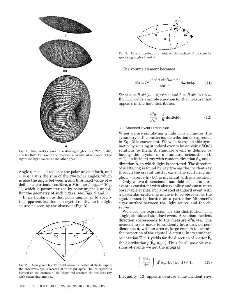
Angle � � � � replaces the polar angle � for b, and� � � is the sum of the two polar angles, whichis also the angle between a and b. A fixed value of �defines a particular surface, a Minnaert’s cigar4 (Fig.1), which is parameterized by polar angles � and �.For the geometry of such cigars, see Figs. 2 and 3.
In particular note that polar angles �, �� specifythe apparent location of a crystal relative to the lightsource as seen by the observer (Fig. 3).
The volume element becomes
d3a � R3sin2 � sin2(� � �)
sin4 �d�d�d�. (11)
Since a � R sin�� � ���sin � and b � R sin ��sin �,Eq. (11) yields a simple equation for the measure thatappears in the halo distribution:
d3a
a2b2 �1R d�d�d�. (12)
D. Standard-Event Distribution
When we are simulating a halo on a computer, thesymmetry of the scattering distribution as expressedin Eq. (2) is convenient. We wish to exploit this sym-metry by reusing standard events by applying SO(3)rotations to them. A standard event is defined byhaving the crystal in a standard orientation �U� 1�, an incident ray with random direction a0, and adirection b0 in which light is scattered. The directionof scattering is found by ray tracing the incident raythrough the crystal until it exits. The scattering an-gle, � � arccos�a0 · b0�, is invariant with any rotation.
Only a two-dimensional manifold of a standardevent is consistent with observability and constitutesobservable events. For a rotated standard event witha particular scattering angle � to be observable, thecrystal must be located on a particular Minnaert’scigar surface between the light source and the ob-server.
We need an expression for the distribution of asingle, simulated standard event. A random incidentdirection corresponds to the measure d2a0�4�. Theincident ray is made to randomly hit a disk perpen-dicular to a0 with an area �0 large enough to containthe projection of the crystal. A crystal in its standardorientation U � 1 yields for the direction of scatter b0
the distribution p�b0|a0, 1�. Thus for all possible ver-sions of events we get the integral
� d2a0
4� � d2b0p(b0|a0, 1) � 1. (13)
Inequality (13) appears because some incident rays
Fig. 1. Minnaert’s cigars for scattering angles of (a) 22°, (b) 45°,and (c) 150°. The eye of the observer is located at one apex of thecigar, the light source at the other apex.
Fig. 2. Cigar geometry. The light source is located at the left apex;the observer’s eye is located at the right apex. The ice crystal islocated on the surface of the cigar and scatters the incident raywith scattering angle �.
Fig. 3. Crystal located at a point on the surface of the cigar byspecifying angles � and �.
hit the disk outside the projection of the crystal.These events are discarded.
In the computer simulation of a halo a large num-ber of standard events are produced, and the naturalquestion is how to use them to compute Z, or ratherdZ/d2b, the halo intensity distribution.
E. Rewriting Z in Terms of Standard Events
We can write the previously computed expression forthe properly normalized, observed scattering powerby using a Dirac delta function:
Z �4R
�2 � d3a
a2 � d3b
b2 �(a b
� R) �DUQ(U)p(b|a, U). (14)
We want to rewrite Eq. (14) in terms of contributionsfrom standard events �a0, b0�. This obviously requiresrotations of the arguments of p in the integrand to thestandard orientation. This means introducing ro-tated versions a0 and b0 of the real ray directions suchthat a � Ua0 and b � Ub0. To that end we note thatthe integration over the parameters of the SO(3) ro-tation U can be written as the integration over thepreimages a0, b0 of the directions a, b, with a Diracdelta function securing the correct pairwise scalarproduct, i.e.,
DU � d2a0d2b0�(a0 · b0 � a · b). (15)
Equation (15) yields, when the symmetry [Eq. (2)] ofp is used,
Z �4R
�2 � d3a
a2 � d3b
b2 �(a b � R)
� � d2a0d2b0�(a0 · b0 � a · b)Q(U)p(b0|a0, 1).
(16)
After some reordering, Eq. (16) can be written in theconvenient form
Z �� d2a0
4� � d2b0p(b0|a0, 1)W(a0, b0), (17)
i.e., as an integration over standard events �a0, b0�with one weight factor p that handles the outcome of
the ray tracing and a second weight factor W repre-senting their total contribution to Z, which is
W(a0, b0) �16R
� � d3a
a2 � d3b
b2 �(a b � R)�(a0 · b0
� a · b)Q(U). (18)
Here U is seen as depending on a, b, a0, and b0.Explicitly we have
U �
aa0T bb0
T � cos �(ab0T ba0
T) (a � b)(a0 � b0)T
sin2 �,
(19)
where the vectors are considered to be column matri-ces and the superscript T denotes the matrix trans-pose.
The expression for W suggests that bipolar angleswould be convenient, yielding
W(a0, b0) �16� �
0
�
d� �0
�
d� �0
2�
d��(cos �
� a0 · b0)Q(U). (20)
The Dirac delta function fixes the value of � and thusa definite cigar, as expected; a rotation of directionsa0 and b0 cannot change their relative angle. Elimi-nating the � integral gives a simple expression for theevent weight:
W �32�
sin � �0
�d�
� �0
2�d�
2�Q(U), (21)
where U is to be regarded now as a function of �, �,and �. The weight is evenly distributed over cigarangles � and �, apart from the factor Q�U�, whichmodifies the weight distribution depending on thecrystal orientation associated with a particular pointon the cigar.
The weight distribution is seen to decompose intotwo parts, the intrinsic cigar weight that is propor-tional to ���sin �� and the factor Q�U� that modifiesthe uniform cigar measure
d�
�
d�
2�
by suppressing points on the cigar that correspond toless probable crystal orientations.
We see that effectively we have split the halo in-tensity distribution operationally into four factors,one describing a single crystal scattering in a stan-dard crystal frame, another that gives a total recy-
cling weight for its contribution assuming isotropiccrystal orientations, a third that gives its distributionover the associated cigar, and finally one that takesinto account the actual distribution of crystal orien-tations in the form of an acceptance factor propor-tional to Q�U�. This amounts to
Z � d2a0 � d2b0p(b0|a0, 1)
��
sin �
��0
�d�
� �0
2�d�
2�
� Q(U). (22)
Noting that the angles as seen from the observer are�, �� rather than ��, ��, Eq. (22) implies the observeddistribution:
dZ �d2a0 � d2b0p(b0|a0, 1)
��
sin �
�d
�
d�
2�
� Q(U), (23)
where is restricted to the interval �0, ��.This factorization is not unique but turns out to be
convenient for implementation of our computer algo-rithm.
3. Implementation
The algorithm that we use can be summarized asfollows:
(1) Assume a standard orientation of the crystalsuch that the main axis of the crystal is in the zdirection (vertical): One of the crystal side faces isparallel to the xz plane. This defines the standardframe U � 1. Generate a random incident ray; raytrace it through the crystal to get a scattered ray. Thedirections of the incident and scattered rays �a0, b0�then completely specify the event, given the standardorientation of the crystal.
(2) The scattering angle � � arccos�a0 · b0� definesa specific Minnaert’s cigar with its axis pointing awayfrom the light source at O toward the observer at R.The recycling weight of an event with a scatteringangle � is proportional to ��sin �. We implement thisweight by reusing each standard event a number oftimes that is proportional to this weight, where wehave normally chosen the proportionality factor K� 20. The choice of the K factor requires some exper-imentation. If Q�U� is narrow, this factor may be setfairly large in order to reduce computation time. In
the opposite case, as in the case of a random orien-tation of the crystals, a too large factor overexposesthe halo display.
(3) For each use of a standard event, select a pointon the cigar by randomly choosing polar angles � inthe interval �0, �� and � in �0, 2��. This implementsthe measure
d�
�
d�
2�.
Note that the random choice of � is equivalent tochoosing the observer’s polar angle randomly in�0, ��. Given the vector R from the light source to theobserver, the polar angles uniquely determine therotation U that gives the orientation of the crystal forthe observable event.
(4) We finally determine the value of Q�U� asso-ciated with the actual rotated crystal orientation andplot a point in the sky in the reverse direction�b�, �� of the scattered ray with a probability pro-portional to this value.
The weight ��sin � diverges for backscattering, �� �. Such events, as seen by the observer, are con-centrated either in the direction of the light source orin the opposite direction or correspond to rays scat-tered by crystals far away. The divergence is a con-sequence of our approximation being valid only forcrystal distances that are small compared with themean free path. We handle this divergence by settingthe weight for scattering angles larger than 179°equal to the weight at 179°.
4. Limiting Case
The model here also allows us to describe and simu-late what happens when the distance between thelight source and the observer is large. This reducesthe influence of parts of the Minnaert’s cigar that arefar from the observer. There could be several reasonsfor this:
(1) The cloud of ice crystals is finite in extension.(2) Rays from distant crystals are absorbed by air.
There is also an intensity threshold for the eye belowwhich it does not register light.
(3) Double scattering and defects, particularly insmaller crystals, spread the rays away from the orig-inal, single-scattering direction.
(4) Possibly diffractive effects could, for very smallcrystals, also spread the light and diminish the lightintensity.
A simple way to simulate the distance dependenceis to cut away more distant parts of the cigar bygenerating points on the cigar only within a smallsphere of radius r, centered at the position of theobserver. A light source at an infinite distance thencorresponds to letting this radius go to zero. Simplegeometrical considerations (see Fig. 4) imply that ifwe assume r �� R we have for Eq. (19)
Thus in the limiting case of an infinite distance to thesource (parallel-light halo) the weight is independentof the scattering angle �. We have used this as aconvenient way to check the simulation and to verifythat we recover the ordinary parallel-light halos asr →0.
5. New Results
We give a new version of the fish-eye atlas for theoriented plate (Fig. 5) and singly oriented columncrystals (Fig. 6) for source elevations from 10° to 60°and also for Parry-oriented crystals (Fig. 7). The ori-ented plate crystals have an axis tip angle of 1.0°from the vertical and a c�a ratio of 0.3. The columncrystals have an axis tip angle of 0.5° from the hori-zontal and a c�a ratio of 2.0. For the Parry simula-tions we assumed that the normal of a side face of thecrystal had a tip angle of 1.5° from the vertical andthat the crystal had a c�a ratio of 2.0. The distribu-tion in the tip angle is a Gaussian distribution withzero mean and a standard deviation equal to the tipangle. The c�a ratio is defined conventionally as theratio between the distance across a basal face of acrystal and the distance between the basal faces. Inall the fish-eye projections the zenith is at the centerof the plot, the circular border represents the horizon,and the distance from the border to the center is alinear function of altitude.
6. Discussion
The halos in the atlas formed by the oriented platecrystals (Fig. 5) are in shape and size similar to thecorresponding halos given in our earlier simulations.1Strong, well-developed superparhelia stretch out ob-
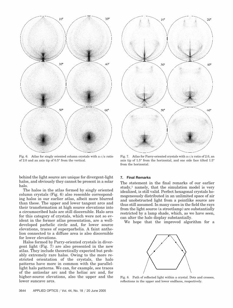
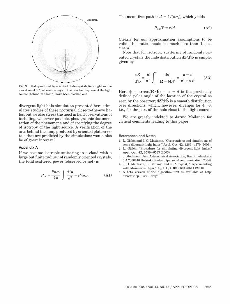
liquely and upward from the source at lower eleva-tions. There is also a weak parhelic circle. A bright,well-defined light pillar appears not only at lowerlight elevations but also at high elevations. A distinctpart of the parhelic circle reveals the 22° parheliastretching horizontally inward to the source. Thefaint arcs of the 120° parhelia can still be seen forhigher source elevations in the new atlas, albeitweaker than before. The circumzenithal as well asthe circumhorizontal arcs are less distinct in the newatlas but otherwise similar to their presentationsgiven in the earlier version of the atlas. New andinteresting features are the arcs and bright spotsappearing between the parhelic circle and the super-parhelia. These features are due to crystals where theray enters one of the side faces, makes an odd numberof reflections in the endfaces, and exits through a sideface as illustrated in Fig. 8. For a crystal with avertical main axis this ray path is horizontally equiv-alent to a reflection in a vertical mirror, and verticallythe ray is scattered back in the opposite direction.These features are located behind the light source asseen by the observer. This can be seen in Fig. 9 wherewe have excluded rays from the source in the back-ward hemisphere, and these arcs then practically dis-appear. Note that features associated with crystals
Fig. 4. Restricting the cigar to crystals located within a spherewith radius r around the observer. If r � R, the distance betweenthe observer and the light source, we have
�max � arcsin rR sin �.
Fig. 5. Atlas for oriented plate crystals with a c�a ratio of 0.3 andan axis tip of 1° from the horizontal.
behind the light source are unique for divergent-lighthalos, and obviously they cannot be present in a solarhalo.
The halos in the atlas formed by singly orientedcolumn crystals (Fig. 6) also resemble correspond-ing halos in our earlier atlas, albeit more blurredthan these. The upper and lower tangent arcs andtheir transformation at high source elevations intoa circumscribed halo are still discernible. Halo arcsfor this category of crystals, which were not so ev-ident in the former atlas presentation, are a well-developed parhelic circle and, for lower sourceelevations, traces of superparhelia. A faint anthe-lion connected to a diffuse area is also discerniblefor lower elevations.
Halos formed by Parry-oriented crystals in diver-gent light (Fig. 7) are also presented in the newatlas. They include theoretically expected but prob-ably extremely rare halos. Owing to the more re-stricted orientation of the crystals, the halopatterns have more in common with the parallel-light halo patterns. We can, for example, see tracesof the antisolar arc and the heliac arc and, forhigher-source elevations, also the upper and thelower suncave arcs.
7. Final Remarks
The statement in the final remarks of our earlierstudy,1 namely, that the simulation model is veryidealized, is still valid. Perfect hexagonal crystals ho-mogeneously distributed in an unlimited space of airand unobstructed light from a pointlike source arethus still assumed. In many cases in the field the raysfrom the light source (a streetlamp) are substantiallyrestricted by a lamp shade, which, as we have seen,can alter the halo display substantially.
We hope that the improved algorithm for a
Fig. 6. Atlas for singly oriented column crystals with a c�a ratioof 2.0 and an axis tip of 0.5° from the vertical.
Fig. 7. Atlas for Parry-oriented crystals with a c�a ratio of 2.0, anaxis tip of 1.5° from the horizontal, and one side face tilted 1.5°from the horizontal.
Fig. 8. Path of reflected light within a crystal. Dots and crosses,reflections in the upper and lower endfaces, respectively.
divergent-light halo simulation presented here stim-ulates studies of these nocturnal close-to-the-eye ha-los, but we also stress the need in field observations ofincluding, wherever possible, photographic documen-tation of the phenomena and of specifying the degreeof isotropy of the light source. A verification of thearcs behind the lamp produced by oriented plate crys-tals that are predicted by the simulations would alsobe of great interest.5
Appendix A
If we assume isotropic scattering in a cloud with alarge but finite radius r of randomly oriented crystals,the total scattered power (observed or not) is
Ptot �Pn�0
4� � d3a
a2 � Pn�0r. (A1)
The mean free path is d � 1��n�0�, which yields
Ptot�P � r�d. (A2)
Clearly for our approximation assumptions to bevalid, this ratio should be much less than 1, i.e.,r �� d.
Note that for isotropic scattering of randomly ori-ented crystals the halo distribution dZ/d2b is simple,given by
dZ
d2b�
R
�3 �0
�db
(R � bb)2�
� �
�3 sin . (A3)
Here � arccos�R · b� � � � � is the previouslydefined polar angle of the location of the crystal asseen by the observer; dZ/d2b is a smooth distributionover directions, which, however, diverges for →0,i.e., for the part of the halo close to the light source.
We are greatly indebted to Jarmo Moilanen forcritical comments leading to this paper.
References and Notes1. L. Gislén and J. O. Mattsson, “Observations and simulations of
some divergent-light halos,” Appl. Opt. 42, 4269–4279 (2003).2. L. Gislén, “Procedure for simulating divergent-light halos,”
3 A 2, 00140 Helsinki, Finland (personal communication, 2004).4. J. O. Mattsson, L. Bärring, and E. Almqvist, “Experimenting
with Minnaert’s Cigar,” Appl. Opt. 39, 3604–3611 (2000).5. A beta version of the algorithm unit is available at http:
//www.thep.lu.se/�larsg/.
Fig. 9. Halo produced by oriented plate crystals for a light sourceelevation of 30°, where the rays in the rear hemisphere of the lightsource (behind the lamp) have been blocked out.