www.ijatir.org ISSN 2348–2370 Vol.08,Issue.21, November-2016, Pages:4079-4083 Copyright @ 2016 IJATIR. All rights reserved. Improved Operation of an UPQC by Addition of a Super Capacitor Energy Storage System RAGALA RAJANI 1 , B. KOTESWARRAO 2 1 PG Scholar, Dept of EEE, VNR College of Engineering, Chintalapudi, Ponnuru, Guntur (Dt), AP, India. 2 Assistant Professor, Dept of EEE, VNR College of Engineering, Chintalapudi, Ponnuru, Guntur (Dt), AP, India. Abstract: In the proposed concept UPQC with Super Capacitor for fast energy storage super capacitor can be used Modern power grids must be highly reliable and provide power with a high quality. Power quality issues like voltage sags or current harmonics must be minimized, in order to achieve high levels of reliability in the system. One possible way to overcome such problems is through the utilization of active power filters like a Unified Power Quality Conditioner (UPQC). On the other hand, Superconducting Magnetic Energy Storage (SMES) is one of the most promising superconducting devices, considering its possible applications in power systems. This concept contains a combination of a SMES with a UPQC for power quality improvement in an electric grid. Through the utilization of a SMES unit, it is possible to increase the stored energy in the DC link of the UPQC, thus improving the system capacity to overcome power quality issues. Voltage sags and current harmonics are simulated and the system behavior is demonstrated. Keywords: UPQC, SMES, Power Quality. I. INTRODUCTION The modern equipment’s that are used in home are very sensitive and prone to harmonics as well as voltage disturbances with poor power factor. The power quality problem is also due to the different faults conditions occurring on the power system network. These conditions cause voltage sag or swell in the system and malfunctioning of devices which damages the sensitive loads [1]. The mitigation of these on the source and load sides is most important for improving the reliability as well as performance on the system. Unified Power Quality Conditioner (UPQC) is expected to be one of the most powerful solutions to large capacity loads that are sensitive to the changes in supply voltage, flicker or imbalance. The UPQC has a single topology that combines series active power filter and shunt active power filter with a common DC link. These two are connected in a back to back configuration [2]. Shunt active power filter compensates all current related distortions and series active power filter compensates all voltage related distortions. The compensation can be done effectively, if there is an effective DC link. The operation of both series active power filter and shunt active power filter are based on voltage source converter technique. The shunt compensator takes care of reactive power compensation, current harmonic compensation, load unbalance compensation and power factor improvement. The series compensator acts for voltage harmonics, voltage sag or swells, flickering etc., with the harmonic isolation between load and supply [3-4]. The super capacitor is used as a battery storage device across the DC link for short time duration. The energy can be stored in the form of batteries, flywheels, compressed air, hydraulic systems and super conducting energy storage systems [5]. A configuration with STATCOM-super capacitor energy storage system is used to enhance power system stability and quality [6]. Super capacitors are also find applications in metro vehicles and hybrid electric vehicles [7], also in traction [8]. The battery has a high storage capacity but unreliable and flywheels requires a lot of maintenance. The discharge rate is slower in batteries because of slower chemical process. But now the future is turned to higher rate of charging and discharging the energy which is possible with the super capacitors. The super capacitors stores less energy however the power transfer capability is high compared to the conventional batteries. The rate of discharge while compensation is fast and it takes only a small current for charging [9]. Use of super capacitor is proposed in UPQC scheme as it is characterized by less weight, faster charge/discharge cycle time, higher power density, higher efficiency and almost maintenance free. The paper [10-11] explains the power circuit modelled as a 3- phase 4- wire system with a non-linear load that is composed of 3- phase diode-bridge rectifier with RC load in the DC side [12-13]. II.SYSTEM OVERVIEW The designed system is depicted in Fig.1. The simulated grid contains a power source, which was simulated using a three phase programmable power source in Simulink, a pure resistive load and the hybrid system consisting of the UPQC+SMES. The series active filter that builds the UPQC is placed close to the power source and the shunt filter is placed close to the load. Although it is possible to choose a reverse configuration (shunt filter close to the source and series filter close to the load) this arrangement was chosen because it allows a better controllability of the DC bus
Transcript
www.ijatir.org
ISSN 2348–2370
Vol.08,Issue.21,
November-2016,
Pages:4079-4083
Copyright @ 2016 IJATIR. All rights reserved.
Improved Operation of an UPQC by Addition of a Super Capacitor Energy
Storage System RAGALA RAJANI
1, B. KOTESWARRAO
2
1PG Scholar, Dept of EEE, VNR College of Engineering, Chintalapudi, Ponnuru, Guntur (Dt), AP, India.
2Assistant Professor, Dept of EEE, VNR College of Engineering, Chintalapudi, Ponnuru, Guntur (Dt), AP, India.
Abstract: In the proposed concept UPQC with Super
Capacitor for fast energy storage super capacitor can be used
Modern power grids must be highly reliable and provide
power with a high quality. Power quality issues like voltage
sags or current harmonics must be minimized, in order to
achieve high levels of reliability in the system. One possible
way to overcome such problems is through the utilization of
active power filters like a Unified Power Quality Conditioner
(UPQC). On the other hand, Superconducting Magnetic
Energy Storage (SMES) is one of the most promising
superconducting devices, considering its possible
applications in power systems. This concept contains a
combination of a SMES with a UPQC for power quality
improvement in an electric grid. Through the utilization of a
SMES unit, it is possible to increase the stored energy in the
DC link of the UPQC, thus improving the system capacity to
overcome power quality issues. Voltage sags and current
harmonics are simulated and the system behavior is
demonstrated.
Keywords: UPQC, SMES, Power Quality.
I. INTRODUCTION
The modern equipment’s that are used in home are very
sensitive and prone to harmonics as well as voltage
disturbances with poor power factor. The power quality
problem is also due to the different faults conditions
occurring on the power system network. These conditions
cause voltage sag or swell in the system and malfunctioning
of devices which damages the sensitive loads [1]. The
mitigation of these on the source and load sides is most
important for improving the reliability as well as
performance on the system. Unified Power Quality
Conditioner (UPQC) is expected to be one of the most
powerful solutions to large capacity loads that are sensitive
to the changes in supply voltage, flicker or imbalance. The
UPQC has a single topology that combines series active
power filter and shunt active power filter with a common DC
link. These two are connected in a back to back
configuration [2]. Shunt active power filter compensates all
current related distortions and series active power filter
compensates all voltage related distortions. The
compensation can be done effectively, if there is an effective
DC link. The operation of both series active power filter and
shunt active power filter are based on voltage source
converter technique. The shunt compensator takes care of
reactive power compensation, current harmonic
compensation, load unbalance compensation and power
factor improvement. The series compensator acts for voltage
harmonics, voltage sag or swells, flickering etc., with the
harmonic isolation between load and supply [3-4].
The super capacitor is used as a battery storage device
across the DC link for short time duration. The energy can be
stored in the form of batteries, flywheels, compressed air,
hydraulic systems and super conducting energy storage
systems [5]. A configuration with STATCOM-super
capacitor energy storage system is used to enhance power
system stability and quality [6]. Super capacitors are also
find applications in metro vehicles and hybrid electric
vehicles [7], also in traction [8]. The battery has a high
storage capacity but unreliable and flywheels requires a lot
of maintenance. The discharge rate is slower in batteries
because of slower chemical process. But now the future is
turned to higher rate of charging and discharging the energy
which is possible with the super capacitors. The super
capacitors stores less energy however the power transfer
capability is high compared to the conventional batteries.
The rate of discharge while compensation is fast and it takes
only a small current for charging [9]. Use of super capacitor
is proposed in UPQC scheme as it is characterized by less
weight, faster charge/discharge cycle time, higher power
density, higher efficiency and almost maintenance free. The
paper [10-11] explains the power circuit modelled as a 3-
phase 4- wire system with a non-linear load that is composed
of 3- phase diode-bridge rectifier with RC load in the DC
side [12-13].
II.SYSTEM OVERVIEW
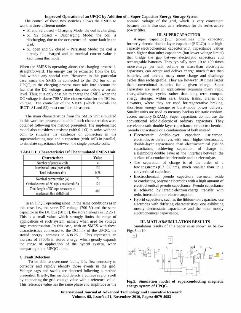
The designed system is depicted in Fig.1. The simulated
grid contains a power source, which was simulated using a
three phase programmable power source in Simulink, a pure
resistive load and the hybrid system consisting of the
UPQC+SMES. The series active filter that builds the UPQC
is placed close to the power source and the shunt filter is
placed close to the load. Although it is possible to choose a
reverse configuration (shunt filter close to the source and
series filter close to the load) this arrangement was chosen
because it allows a better controllability of the DC bus
RAGALA RAJANI, B. KOTESWARRAO
International Journal of Advanced Technology and Innovative Research