Improved performance of porphyrin-based dye sensitised solar cells by phosphinic acid surface treatment Alessandra Allegrucci, a Naomi A. Lewcenko, a Attila J. Mozer, b Lynn Dennany, b Pawel Wagner, b David L. Officer, * b Kenji Sunahara, c Shogo Mori c and Leone Spiccia * a Received 15th May 2009, Accepted 10th June 2009 First published as an Advance Article on the web 22nd June 2009 DOI: 10.1039/b909709k Chemical surface treatment of porphyrin-sensitised titania films using bis-(4-methoxyphenyl)phosphinic acid after dye adsorption, results in large improvements in DSSC efficiencies which originate primarily from higher short circuit currents. The result was attrib- uted to a positive shift in the TiO 2 quasi-Fermi level with simulta- neous retardation of charge recombination. High device performances have been achieved even using simplified electrolyte matrices devoid of the common additives, LiI and t-butylpyridine. Introduction As international concerns about energy and climate change increase, there is an intense global research effort to reduce the cost and improve the performance of solar powered devices. Dye sensitised solar cells (DSSCs) are one such technology that has been intensively investigated since reported by O’Regan and Gr€ atzel in 1991. 1 In a DSSC, the dye, following excitation by light (D + hn / D * ), injects an electron into the TiO 2 conduction band (D * / D + + CB), which then moves through the external circuit converting I 3 / I (typical redox couple) at the platinised counter electrode. Iodide then reduces the oxidised dye (3I + 2D + / 2D + I 3 ). Due to the nanostructured nature of these devices, molecular interactions involving the titania film and the adsorbed dye molecules, 2,3 electrolyte components, 4,5 or treatment agents 6,7 can alter the conduction band potential of the semiconductor causing changes in the open circuit voltage (V oc ) and/ or the short circuit current (J sc ) leading to changes in the overall device efficiency (h){h ¼ V oc J sc FF/ P in , where P in is the power input and FF is the fill factor}. While V oc is dictated by the difference between the quasi-Fermi level of the TiO 2 and the potential of the redox couple, J sc arises from the efficiency of injection from the dye into the TiO 2 and the efficiency of charge collection. Therefore, both values are limited by the recombination processes 2,8,9 that occur when the photoinjected electron recombines with the oxidised dye molecule (R 1 ) or reacts with the oxidised form of the redox couple in the electrolyte (R 2 ). Process R 2 has been well studied 10–14 and has been deemed to have a greater impact on device performance than R 1 . 15 Various strategies are being employed to overcome this intrinsic limitation, many of them aiming to protect exposed sites on the titania surface. Two simple approaches involve protection of the unfunctionalised titania surface by either molecular engineering of the sensitising dye molecule to contain, e.g., long alkyl chains 16 or blocking vacant titania sites by reaction with an organic acid. Co- adsorption of decylphosphonic acid 7 or chenodeoxycholic acid (CDCA) 6 with the dye leads to increased V oc and J sc , while CDCA also has a beneficial effect when added to the electrolyte. Phosphinic acids also form strong interactions with titania 17 but, in contrast to carboxylic or phosphonic acids, they have two organic substituents that can potentially better insulate the titania surface on attachment. Herein, we show that bis-(4-methoxyphenyl)phosphinic acid (BMPPA), which contains two bulky aryl substituents (Fig. 1), is a good candidate as a chemical surface treatment agent. To date, literature reports have predominantly focussed on co- adsorption techniques, where the treatment agent is added to the dye a School of Chemistry, Monash University, Victoria, 3800, Australia. E-mail: [email protected]; Fax: +61 3 9905 4597; Tel: +61 3 9905 4526 b Intelligent Polymer Research Institute, ARC Centre for Excellence for Electromaterials Science, University of Wollongong, Wollongong, 2522, Australia. E-mail: [email protected]; Fax: +61 2 4221 3114; Tel: +61 2 4221 469 c Department of Fine Materials Engineering, Shinshu University, Nagano, 386-8567, Japan Broader context Recombination losses are one major factor that can limit the efficiencies of dye sensitised solar cells (DSSCs). Zinc-porphyrins, for example, are promising alternatives to Ru-sensitisers which exhibit recombination losses. Various strategies are being employed to minimise these losses, many of them aiming to block exposed sites on the nanostructured titania surface. One successful strategy has involved the co-adsorption of organic acids, such as decylphosphonic acid or chenodeoxycholic acid, and the dye. We demonstrate that chemical surface treatment of porphyrin-sensitised titania films using a diarylphosphinic acid, post dye adsorption, results in large improvements in DSSC efficiencies that directly parallel increases in the short circuit currents. Notably, the most striking improvements were found for electrolytes without the additives, i.e., no LiI and/or t-butylpyridine, commonly used to enhance DSSC performance. Controlled functionalisation of the semiconductor surface with carefully selected phosphinic acids, as a tool for improving DSSC efficiencies, is an exciting concept that can be applied for sensitisers where recombination reactions are currently limiting and opens up new possibilities for designing simplified electrolyte systems. This journal is ª The Royal Society of Chemistry 2009 Energy Environ. Sci., 2009, 2, 1069–1073 | 1069 COMMUNICATION www.rsc.org/ees | Energy & Environmental Science Downloaded on 19/04/2013 14:46:23. Published on 22 June 2009 on http://pubs.rsc.org | doi:10.1039/B909709K View Article Online / Journal Homepage / Table of Contents for this issue
Transcript
COMMUNICATION www.rsc.org/ees | Energy & Environmental Science
Dow
nloa
ded
on 1
9/04
/201
3 14
:46:
23.
Publ
ishe
d on
22
June
200
9 on
http
://pu
bs.r
sc.o
rg |
doi:1
0.10
39/B
9097
09K
View Article Online / Journal Homepage / Table of Contents for this issue
Improved performance of porphyrin-based dye sensitised solar cells byphosphinic acid surface treatment
Alessandra Allegrucci,a Naomi A. Lewcenko,a Attila J. Mozer,b Lynn Dennany,b Pawel Wagner,b
David L. Officer,*b Kenji Sunahara,c Shogo Moric and Leone Spiccia*a
Received 15th May 2009, Accepted 10th June 2009
First published as an Advance Article on the web 22nd June 2009
DOI: 10.1039/b909709k
Chemical surface treatment of porphyrin-sensitised titania films
using bis-(4-methoxyphenyl)phosphinic acid after dye adsorption,
results in large improvements in DSSC efficiencies which originate
primarily from higher short circuit currents. The result was attrib-
uted to a positive shift in the TiO2 quasi-Fermi level with simulta-
neous retardation of charge recombination. High device
performances have been achieved even using simplified electrolyte
matrices devoid of the common additives, LiI and t-butylpyridine.
Introduction
As international concerns about energy and climate change increase,
there is an intense global research effort to reduce the cost and
improve the performance of solar powered devices. Dye sensitised
solar cells (DSSCs) are one such technology that has been intensively
investigated since reported by O’Regan and Gr€atzel in 1991.1 In
a DSSC, the dye, following excitation by light (D + hn / D*), injects
an electron into the TiO2 conduction band (D* / D+ + CB), which
then moves through the external circuit converting I3� / I� (typical
redox couple) at the platinised counter electrode. Iodide then reduces
the oxidised dye (3I� + 2D+ / 2D + I3�). Due to the nanostructured
aSchool of Chemistry, Monash University, Victoria, 3800, Australia.E-mail: [email protected]; Fax: +61 3 9905 4597; Tel:+61 3 9905 4526bIntelligent Polymer Research Institute, ARC Centre for Excellence forElectromaterials Science, University of Wollongong, Wollongong, 2522,Australia. E-mail: [email protected]; Fax: +61 2 4221 3114; Tel: +612 4221 469cDepartment of Fine Materials Engineering, Shinshu University, Nagano,386-8567, Japan
Broader context
Recombination losses are one major factor that can limit the efficie
example, are promising alternatives to Ru-sensitisers which exhibit
minimise these losses, many of them aiming to block exposed sites o
involved the co-adsorption of organic acids, such as decylphosphon
that chemical surface treatment of porphyrin-sensitised titania films u
improvements in DSSC efficiencies that directly parallel increas
improvements were found for electrolytes without the additives, i
DSSC performance. Controlled functionalisation of the semiconduc
improving DSSC efficiencies, is an exciting concept that can be app
limiting and opens up new possibilities for designing simplified elec
This journal is ª The Royal Society of Chemistry 2009
nature of these devices, molecular interactions involving the titania
film and the adsorbed dye molecules,2,3 electrolyte components,4,5 or
treatment agents6,7 can alter the conduction band potential of the
semiconductor causing changes in the open circuit voltage (Voc) and/
or the short circuit current (Jsc) leading to changes in the overall
device efficiency (h) {h ¼ Voc� Jsc� FF/Pin, where Pin is the power
input and FF is the fill factor}. While Voc is dictated by the difference
between the quasi-Fermi level of the TiO2 and the potential of the
redox couple, Jsc arises from the efficiency of injection from the dye
into the TiO2 and the efficiency of charge collection. Therefore, both
values are limited by the recombination processes2,8,9 that occur when
the photoinjected electron recombines with the oxidised dye molecule
(R1) or reacts with the oxidised form of the redox couple in the
electrolyte (R2). Process R2 has been well studied10–14 and has been
deemed to have a greater impact on device performance than R1.15
Various strategies are being employed to overcome this intrinsic
limitation, many of them aiming to protect exposed sites on the
titania surface. Two simple approaches involve protection of
the unfunctionalised titania surface by either molecular engineering of
the sensitising dye molecule to contain, e.g., long alkyl chains16 or
blocking vacant titania sites by reaction with an organic acid. Co-
adsorption of decylphosphonic acid7 or chenodeoxycholic acid
(CDCA)6 with the dye leads to increased Voc and Jsc, while CDCA
also has a beneficial effect when added to the electrolyte. Phosphinic
acids also form strong interactions with titania17 but, in contrast to
carboxylic or phosphonic acids, they have two organic substituents
that can potentially better insulate the titania surface on attachment.
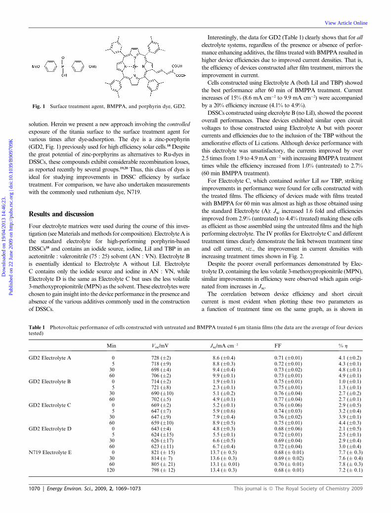
Herein, we show that bis-(4-methoxyphenyl)phosphinic acid
(BMPPA), which contains two bulky aryl substituents (Fig. 1), is
a good candidate as a chemical surface treatment agent.
To date, literature reports have predominantly focussed on co-
adsorption techniques, where the treatment agent is added to the dye
ncies of dye sensitised solar cells (DSSCs). Zinc-porphyrins, for
recombination losses. Various strategies are being employed to
n the nanostructured titania surface. One successful strategy has
ic acid or chenodeoxycholic acid, and the dye. We demonstrate
sing a diarylphosphinic acid, post dye adsorption, results in large
es in the short circuit currents. Notably, the most striking
.e., no LiI and/or t-butylpyridine, commonly used to enhance
tor surface with carefully selected phosphinic acids, as a tool for
lied for sensitisers where recombination reactions are currently
2400 source meter. Cells were biased from +800 to �300 mV with
10 mV steps and a 40 ms settling time (delay between application of
the potential and current measurement) Short circuit current and
open circuit voltage decays were determined by illuminating devices
with a 635 nm diode laser, reducing the intensity and measuring the
voltage or current response with a fast multimeter.19 For the IPCE
measurements, cells constructed with dyed titania films that had
been treated with BMPPA for various times (0, 5, 30, 60 min) were
held under short circuit conditions and illuminated with mono-
chromatic light in 10 nm steps using a Newport lamp. Electron
densities (ED, cm�3) at the same illumination intensities were
determined by a charge extraction method where the applied light
bias on the device was removed, accompanied by a simultaneous
switch from open circuit to short circuit. The resulting current was
integrated and the electron density was calculated from the amount
of charge extracted.
Acknowledgements
The authors thank the Australian Research Council and the
Australian Centre of Excellence in Electromaterials Science for
funding and JGC Catalysts and Chemicals Ltd. Kitakyushu-Shi,
Japan for providing the titania paste. AA thanks EES and UNSW
for the best poster award received at the 17th International Confer-
ence on Photochemical Conversion and Storage of Solar Energy held
in Sydney in July 2008.
Notes and references
1 B. O’Regan and M. Gr€atzel, Nature, 1991, 353, 737–740.2 S. Nakade, T. Kanzaki, W. Kubo, T. Kitamura, Y. Wada and
S. Yanagida, J. Phys. Chem. B, 2005, 109, 3480–3487.3 J.-W. Lee, K.-J. Hwang, D.-W. Park, K.-H. Park, W.-G. Shim and
S.-C. Kim, J. Nanosci. Nanotechnol., 2007, 7, 3717–3721.4 S. Nakade, T. Kanzaki, S. Kambe, Y. Wada and S. Yanagida,
Langmuir, 2005, 21, 11414–11417.5 H. Paulsson, L. Kloo, A. Hagfeldt and G. Boschloo, J. Electroanal.
Chem., 2006, 586, 56–61.6 N. R. Neale, N. Kopidakis, J. van de Lagemaat, M. Gr€atzel and
A. J. Frank, J. Phys. Chem. B, 2005, 109, 23183–23189.7 P. Wang, S. M. Zakeeruddin, R. Humphry-baker, J. E. Moser and
M. Gr€atzel, Adv. Mater., 2003, 15, 2101–2104.
This journal is ª The Royal Society of Chemistry 2009
8 S. A. Haque, E. Palomares, B. M. Cho, A. N. M. Green, N. Hirata,D. R. Klug and J. R. Durrant, J. Am. Chem. Soc., 2005, 127, 3456–3462.
9 S. A. Haque, Y. Tachibana, R. L. Willis, J. E. Moser, M. Gr€atzel,D. R. Klug and J. R. Durrant, J. Phys. Chem. B, 2000, 104, 538–547.
10 A. J. Frank, N. Kopidakis and J. van de Lagemaat, Coord. Chem.Rev., 2004, 248, 1165–1179.
11 T. Kanzaki, S. Nakade, Y. Wada and S. Yanagida, Photochem.Photobiol. Sci., 2006, 5, 389–394.
12 Q. Wang, S. Ito, M. Gr€atzel, F. Fabregat-Santiago, I. Mora-Sero,J. Bisquert, T. Bessho and H. Imai, J. Phys. Chem. B, 2006, 110,25210–25221.
13 F. Fabregat-Santiago, J. Garcia-Canadas, E. Palomares,J. N. Clifford, S. A. Haque, J. R. Durrant, G. Garcia-Belmonte andJ. Bisquert, J. Appl. Phys., 2004, 96, 6903–6907.
14 J. R. Durrant, S. A. Haque and E. Palomares, Coord. Chem. Rev.,2004, 248, 1247–1257.
15 D. Kuciauskas, M. S. Freund, H. B. Gray, J. R. Winkler andN. S. Lewis, J. Phys. Chem. B, 2001, 105, 392–403.
16 N. Koumura, Z.-S. Wang, S. Mori, M. Miyashita, E. Suzuki andK. Hara, J. Am. Chem. Soc., 2006, 128, 14256–14257.
17 G. Guerrero, P. H. Mutin and A. Vioux, Chem. Mater., 2001, 13,4367–4373.
18 W. M. Campbell, K. W. Jolley, P. Wagner, K. Wagner, P. J. Walsh,K. Gordon, L. Schmidt-Mende, M. K. Nazeeruddin, Q. Wang,M. Gr€atzel and D. L. Officer, J. Phys. Chem. C, 2007, 111, 11760–11762.
19 A. J. Mozer, P. Wagner, D. L. Officer, G. G. Wallace,W. M. Campbell, M. Miyashita, K. Sunahara and S. Mori, Chem.Commun., 2008, 4741–4743.
20 A. Forneli, M. Planells, M. A. Sarmentero, E. Martinez-Ferrero,B. C. O’Regan, P. Ballester and E. Palomares, J. Mater. Chem.,2008, 18, 1652–1658.
21 D. F. Watson and G. J. Meyer, Coord. Chem. Rev., 2004, 248, 1391–1406.
22 R. Katoh, C. R. Chim., 2006, 9, 639.23 Q. Wang, W. M. Campbell, E. E. Bonfantani, K. W. Jolley,
D. L. Officer, P. J. Walsh, K. Gordon, R. Humphry-Baker,M. K. Nazeeruddin and M. Gr€atzel, J. Phys. Chem. B, 2005, 109,15397–15409.
24 J.-H. Yum, S.-R. Jang, R. Humphry-Baker, M. Gr€atzel, J.-J. Cid,T. Torres and M. K. Nazeeruddin, Langmuir, 2008, 24, 5636–5640.
25 X.-F. Wang, O. Kitao, H. Zhou, H. Tamiaki and S. Sasaki, J. Phys.Chem. C, 2009, 113, 7954–7961.
26 M. Miyashita, K. Sunuhara, T. Nishikawa, N. Koumura, K. Hara,A. Mori, T. Abe, E. Suzuki and S. Mori, J. Am. Chem. Soc., 2008,130, 17874–17881.
27 D. Kuang, S. Ito, B. Wenger, C. Klein, J. E. Moser, R. Humphry-Baker, S. M. Zakeeruddin and M. Gr€atzel, J. Am. Chem. Soc.,2006, 128, 4146–4154.