Improved Ray Hierarchy Alias Free Shadows Technical Report 2011:09 ISSN 1652-926X Ola Olsson and Ulf Assarsson May 6, 2011 Abstract In this article, we introduce and evaluate several new algorithmic improve- ments to Ray Hierarchies. The improved algorithm is used to produce ray-traced shadows for omni-directional lights in fully dynamic environments. The new al- gorithmic improvements increase culling rate of the traversal algorithm, in some cases dramatically cutting the number of visited nodes. To evaluate performance, we present a GPU implementation using CUDA, which uses a hybrid breadth- depth algorithm to perform the traversal using bounded memory. The results show that the use of improved cone hierarchies is able to produce high quality shadows quickly – for some scenes in real-time. 1 Introduction Shadows, it is well known, are very important for visual fidelity in computer generated images. The most popular algorithm for real-time shadows is shadow mapping, owing to its flexibility and high performance. This technique, while fast, suffers from various forms of aliasing [SD02] and are limited to a single plane of projection. It also requires storage for one or several high resolution shadow maps. Ray tracing, and equivalent techniques, solves the aliasing problems. However, they also generally require ran- dom access to the scene database and do not generally offer real-time performance for dynamic scenes. In this paper we show how ray hierarchies can be improved and applied to bridge the gap between shadow mapping and ray tracers that use scene hierarchies. The new method extends cone hierarchies [RAH07] with several improvements for different scene types. This allows interactive or real-time ray traced (i.e. alias free) shadows for fully dynamic scenes. As the technique requires no hierarchy imposed on the scene data, it is simple to integrate into existing real-time renderers. To improve the cone hierarchies we contribute a novel precise cone/triangle in- tersection test, and extend this to perform early accept of covered cones. We also introduce a two pass traversal, which exploits good blockers to speed traversal. Fur- thermore, we present a novel way to extract coherency by applying a sorting pass when screen space coherency is low, yielding much tighter cone hierarchies. We also con- tribute a practical evaluation on a number of scenes, demonstrating a robust GPU- implementation with bounded memory use. 1
Transcript
Improved Ray Hierarchy Alias Free Shadows
Technical Report 2011:09
ISSN 1652-926X
Ola Olsson and Ulf Assarsson
May 6, 2011
Abstract
In this article, we introduce and evaluate several new algorithmic improve-
ments to Ray Hierarchies. The improved algorithm is used to produce ray-traced
shadows for omni-directional lights in fully dynamic environments. The new al-
gorithmic improvements increase culling rate of the traversal algorithm, in some
cases dramatically cutting the number of visited nodes. To evaluate performance,
we present a GPU implementation using CUDA, which uses a hybrid breadth-
depth algorithm to perform the traversal using bounded memory. The results show
that the use of improved cone hierarchies is able to produce high quality shadows
quickly – for some scenes in real-time.
1 Introduction
Shadows, it is well known, are very important for visual fidelity in computer generated
images. The most popular algorithm for real-time shadows is shadow mapping, owing
to its flexibility and high performance. This technique, while fast, suffers from various
forms of aliasing [SD02] and are limited to a single plane of projection. It also requires
storage for one or several high resolution shadow maps. Ray tracing, and equivalent
techniques, solves the aliasing problems. However, they also generally require ran-
dom access to the scene database and do not generally offer real-time performance for
dynamic scenes.
In this paper we show how ray hierarchies can be improved and applied to bridge
the gap between shadow mapping and ray tracers that use scene hierarchies. The new
method extends cone hierarchies [RAH07] with several improvements for different
scene types. This allows interactive or real-time ray traced (i.e. alias free) shadows for
fully dynamic scenes. As the technique requires no hierarchy imposed on the scene
data, it is simple to integrate into existing real-time renderers.
To improve the cone hierarchies we contribute a novel precise cone/triangle in-
tersection test, and extend this to perform early accept of covered cones. We also
introduce a two pass traversal, which exploits good blockers to speed traversal. Fur-
thermore, we present a novel way to extract coherency by applying a sorting pass when
screen space coherency is low, yielding much tighter cone hierarchies. We also con-
tribute a practical evaluation on a number of scenes, demonstrating a robust GPU-
implementation with bounded memory use.
1
2 Previous Work
Owing to the importance of shadows, there exists a vast corpus of previous work on
shadow algorithms. Several good surveys on the topic provide a more comprehensive
background than allowed by the scope of this article [WPF90, HLHS03, EASW09].
2.1 Shadow Map based methods
The most popular real-time (hard) shadow algorithm is Shadow Mapping, and deriva-
tives thereof. The popularity stems from fast execution on GPUs, low requirements on
scene data organization, and predictable rendering performance. The method suffers
from several kinds of aliasing problems: projective, perspective and depth-precision
aliasing [SD02].
Several approaches attempt to reduce aliasing through warping and/or partition-
ing [LTYM06]. These approaches are generally real-time, but suffer from special cases
which makes them difficult to use in interactive applications.
Partitioning is taken further with Resolution Matched Shadow Maps [LSO07], which
manage a virtual shadow map of very high resolution. Only the pages required for the
current view are allocated and rendered, at the required resolution. Perspective and
projective aliasing is much reduced, but not eliminated. The implementation achieves
real-time performance for moderately large scenes, but is quite complicated to imple-
ment efficiently.
All shadow map techniques need a plane of projection, and therefore need several
rendering passes and shadow maps, to support omni-directional lights, e.g. a cube map
or some other partitioning [For04, LTYM06]. In this paper we present a ray tracing
based solution that does not have this limitation, and avoids all types of aliasing except
depth-precision. The new method also shares the advantage of low requirements on
scene data organization, with shadow mapping.
2.2 Ray Tracing based methods
Ray tracing solves the hard shadow problem exactly, and thus does not suffer from the
aliasing resulting from discretization (perspective, and projective aliasing). General ray
tracing can handle any type of light. However, general ray tracing methods generally
require random access to the scene database, and a highly optimized scene hierarchy.
There are now several publications showing real-time, or interactive, performance
for ray traced solutions of small to moderate scene sizes. The most recent both con-
struct acceleration structures and trace rays on the GPU [ZHWG08, LGS+09].
Alias free shadow maps [AL04], variations and implementations [JLBM05, Arv07,
SEA08], compute an equivalent result to ray traced solutions by performing irregular
rasterization. The most recent work offer interactive performance [SEA08], but re-
quires special geometry. All of these methods need a plane of projection, and conse-
quently, do not support omni-directional light sources.
Cone hierarchies that exploit screen space coherency for fast ray hierarchy con-
struction on the GPU have been demonstrated [RAH07]. They offer real-time, or inter-
active, performance for scenes with high screen space coherency. However, the previ-
ous work does not specifically explore shadows, but instead the discussion centers on
solving specular and glossy phenomena. In this work, we improve this algorithm and
tailor it to the problem of shadows. We also introduce a sorting pass, based on space
filling curves, to improve coherency when there are discontinuities in image space.
2
3 Improved Cone Hierarchy Traversal
The approach taken in this paper is an extension of the Ray-Space Hierarchy algorithm
presented by Roger et al [RAH07]. As noted in their paper, the bottom up construction
used produces inefficient bounding volume hierarchies when there are incoherent rays
near the bottom of the tree. This is because cones become large if the angle between
the rays is large, and these cones then propagate up the bounding volume hierarchy.
Incoherent rays are especially common when tracing reflections and refractions
through several bounces. We instead focus on the problem of shadows, where signif-
icant image space coherency can be expected, for interesting scenes [LSO07]. The
coherency exists because all the shadow rays share one common endpoint, the light;
and because nearby samples usually are located close together in world space.
By focusing on shadows, we can also exploit some special properties of shadow
rays to construct an improved traversal algorithm. Shadow rays are, for example, finite
and all share one endpoint (the light).
However, solely using screen space coherency is not sufficient for constructing effi-
cient ray hierarchies. Discontinuities in the depth buffer can cause large cones near the
bottom of the tree. To address these situations we also propose some novel techniques
for improving coherency before constructing cone trees.
3.1 Algorithm Overview
The basic algorithm consists of the following steps, and follows, more or less the ap-
proach in previous work [RAH07].
1. Rasterize the scene, but store the direct light contribution in a separate render
target (light buffer).
2. Construct a ray hierarchy using the Z buffer and light buffer.
3. Intersect the scene geometry with the ray hierarchy.
4. Set all pixels that correspond to a ray/triangle intersection to black in the light
buffer.
5. Add the light buffer to the frame buffer.
In the first step, the scene is rasterized as per normal, and lighting is computed for
the samples. However, instead of adding the direct light component, this is stored in a
texture, such that it can be added later after shadowing has been computed. Naturally,
it is equally possible to perform a depth only pass first, then compute shadows, and
finally compute shading only where necessary.
Next, the ray hierarchy is constructed in a way similar to a mip-map hierarchy.
Starting from individual rays (which are reconstructed from the z buffer and light po-
sition), a four-way bounding volume tree of cones is constructed [RAH07]. Note that
each leaf location corresponds directly to a sample in the light buffer.
To find which samples are shadowed, each triangle is used to traverse the ray hier-
archy from the root. The traversal step is performed using breadth first traversal. When
all the internal levels in the hierarchy have been traversed, we have a list of ray/triangle
pairs. The ray/triangle pairs are tested for intersection, and if found, the corresponding
light buffer sample is set to black.
Finally the light buffer is simply added, fragment by fragment, to the frame buffer,
producing a correctly lit and shadowed scene.
3
3.2 Precise Cone/Triangle Intersection
The previous work [RAH07], uses bounding spheres around the primitives when travers-
ing the hierarchy. A bounding sphere quite severely overestimates the volume of a tri-
angle, and thus inflates the probability of intersection with a cone or a ray. This leads
to many nodes being traversed needlessly, which is especially problematic for large
triangles, for example walls of buildings, Figure 1 illustrates this problem.
Figure 1: Bounding spheres provide severely over-conservative bounds on triangles, especially
long and skinny triangles. The illustration shows a schematic view of a city street, with tall walls.
In the left version, bounding spheres (red) interact with every ray inside the cone (yellow),
though none actually intersect the wall. To the right, the scene has been subdivided, which
reduces the problem, but at the cost of several times more primitives.
A simple way to attempt to address this problem is to subdivide the scene triangles
(Figure 1 right). However, the tessellation would have to be adaptive to handle different
views, and trades simplicity in intersection for more open traversal nodes.
To better address this problem we instead introduce a more precise cone/triangle in-
tersection test. The new test is based on homogeneous triangle rasterization, and starts
by constructing a perspective projection from the cone. Then, the triangle vertices are
transformed into the cones homogeneous clip space, and the homogeneous edge equa-
tions are constructed from the transformed vertices [AMMH07]. If the signed distance
from any edge to the origin is greater than one, the triangle can be rejected, see Fig-
ure 2(a). The signed distance to the origin is trivially obtained from the edge equations
by normalizing them. Figure 2(b) shows an example which cannot be rejected, as none
of the signed distances are greater than one (d1 and d2 are negative while d0 is positive
but smaller still than one).
d0>1
(a) Rejected triangle.
d0<1
d2<1
d1<1
(b) Intersected triangle.
d0< −1
d2< −1
d1< −1
(c) Accepted triangle.
Figure 2: The triangle is transformed using the cone projection, and the edge equation distances
compared against the unit circle.
We also determine the nearest point on the intersection between the cone and tri-
angle supporting plane, illustrated in Figures 3(b) and 3(c). The distance to this point
4
is used to determine if the cone hits the triangle plane at all: if it is larger than the
longest ray represented, Lmax (Figure 3(a)), then the cone cannot intersect the trian-
gle. This test is implemented by exploiting calculations performed during projection.
We set the far plane distance of the cone projection to Lmax, and align the up direction
of the projection with the normal of the triangle. After projection, the homogeneous
triangle plane equation is formed, and then solved for Znear at the homogeneous point
Pnear = {0,−1, Znear, 1}. Because of the way we chose the far clip distance, the
cone can be rejected if Znear > 1.
α
near far
Lmax
Lmin
axis
(a) Cone properties.
axis
tri normal
(b) A covered cone, with triangle normal.
pfar
pnear
(c) The clip space up direction is
aligned with the triangle normal.
Figure 3: Note, in (a), that the cone angle α is the half spread angle and has a valid range of
[0, π]. Shown in gray are some example rays represented by the cone, with their shortest and
longest lengths, Lmin and Lmax, indicated. In (c), the clip space locations of Pnear and Pfar
are shown.
A problem with the new test is what is sometimes termed the triangle shadow (see
Figure 4. The triangle shadow is the area outside the triangle where none of the edge
distances are less than one. Such triangles are therefore incorrectly classified as inter-
secting. This leads to more nodes than necessary being traversed and can actually lead
to worse culling performance than the sphere test if left unchecked. To solve this we
also construct and test separating planes tangential to the unit circle with the normals
pointing towards the vertices. If all three vertices are outside any of these planes, the
triangle is rejected.
d0<1
d2<1
d1<1
(a) The triangle shadow. (b) Triangle shadow solution.
Figure 4: The triangle shadow is the area outside the triangle, but where no plane distance is
greater than one (a). Our solution, (b), a separating plane is found between each vertex and the
unit circle, and if all vertices are outside any of these, then the triangle is rejected.
For cone angles near and above π/2 the projection becomes unstable. Therefore,
if the angle is greater than π/2 − ε, using some small machine dependent epsilon ε,
5
the angle is rounded up to π/2. For these large angles, the test is changed to check if
all vertices are contained in the complementary cone: if all three points are inside the
complementary cone, then there is no intersection.
3.3 Early accept for covered cones
The new test uses the exact representation of the scene geometry, as opposed to con-
servative bounds. This means that it is now possible to construct a test that determines
if the cone is completely covered by the triangle. Extending the homogeneous test, the
triangle covers the cone if all the distances to the edges are less than the negative one,
see Figure 2(c).
To correctly determine if all the rays represented by the cone has intersected the
covering triangle, one new piece of information is needed: the length of the shortest of
these rays, Lmin. Adding this information is a trivial addition to the tree construction
algorithm. We can then assert whether the farthest point on the intersection between the
cone and the triangle lies closer than the length of the shortest ray. If this is the case, all
the rays must cross the triangle plane, and therefore intersect the triangle. For infinite
rays, this last check can be omitted, as the rays must intersect any triangle covering the
cone.
To determine the nearest crossing, we re-use the logic used to find the nearest cross-
ing point (see Section 3.2). After constructing the clip space triangle plane, we solve
for Zfar at the homogeneous point Pfar = {0, 1, Zfar, 1}, see Figure 3(c). When
constructing the cone projection, the near clip distance is set to Lmin cosα, which is
necessary since we must allow for the fact that the shortest ray may diverge from the
cone axis by the cone angle (see Figure 3(a) for an illustration). Because of this choice
of near plane, if Zfar < −1, then all rays must hit the triangle.
When a cone is found to be completely covered, we can simply set all the corre-
sponding fragments to ”shadowed”, and remove the element from the traversal queue.
As the cone tree is left-balanced and implicit, it is trivial to find the corresponding
range of leaves from any interior node.
Furthermore, since this cone has been identified as covered, we know that it is not
necessary to test any more primitives against it nor any of its children. Thus we can
mark the node in the tree as invalid. As traversal is breadth first we can in the next pass
test each element to see if the parent node is valid, and terminate traversal if not (see
Figure 5).
3.4 Two-Pass traversal
Testing the coverage of triangles helps pruning many branches of the traversal tree.
However, a cone may be covered not by one, but by two or more triangles each covering
only part of the cone. This situation occurs along all interior edges when occluders
consist of more than one triangle, and cannot be detected by the early accept test.
To address this, a variation is introduced that traverses the triangles in two passes.
In the first pass, only those triangles that are good candidates for occlusion are traversed
through the ray hierarchy. After this, if the selected blockers were indeed good, large
portions of the light buffer should be marked as shadowed. Next, the hierarchy is up-
dated, removing those rays that are already in shadow. Finally, all remaining triangles
are traversed using the new smaller cone hierarchy.
It is not immediately obvious what makes a good occluder, but for architectural
scenes, large walls are good candidates. If the first pass does not produce many finished
6
Pass 0
n1
n0
n2 {t0,n0} {t1,n0} {t3,n0} …
{t0} {t1} {t3} …
Pass 1
n3 n4 {t0,n1} {t1,n1} … Pass 2
{t3,n1}Finished: …
Figure 5: In pass 0, all triangles are tested against the root node; those that pass are added to
the traversal queue. In pass 1, the children of the queued nodes are tested; those that pass are
added to the queue for the next level, and those that cover the cone are marked as finished. In
the example, t3 covers the cone in node n1. As a side effect, the corresponding node is marked
as invalid. In pass 2, then, the parent nodes are checked for validity. The circled nodes are thus
trivially terminated.
rays, the update step can be skipped, and thus the only time lost is due to the overhead
of launching kernels and potentially under-utilizing the GPU if there are not enough
large polygons in the first batch. For very large scenes, this overhead is minor. For
some scenes, it may also be beneficial to place occluders manually or automatically
generate them from the scene data.
3.5 Ray Sorting
The naive approach to constructing cone hierarchies from the frame buffer assumes
that the rays are already coherent. While this is a reasonable assumption for shadow
rays shot from continuous surfaces, it starts to break down where there are depth dis-
continuities. An example of a problematic situation is shown in Table 2. However,
while pixels are not directly coherent in screen space, they are still so in world space as
they originate from locations nearby each other. Introducing a ray sorting pass before
hierarchy construction is an attempt to extract this coherency in order to improve cone
tree quality.
Before sorting the rays a compaction step is performed to remove any rays from
pixels that are not affected by the light. Compaction is very cheap, especially com-
pared to sorting. Next, a sorting key based on a space filling curve is constructed for
remaining sample. We use a method inspired by what was presented in [AK87], par-
titioning the direction space into six square 2D spaces, according to the ray direction
major axis coordinate. Within each of the 2D spaces, the ray direction is represented
by the two remaining coordinates, normalized to the range [−1, 1]. From this 2D co-
ordinate, we find the number on a discrete Hilbert curve, with a resolution selected to
efficiently use the bits in the 32-bit sorting key. The rays are then sorted according to
these keys using a fast radix sort. After sorting using of the Hilbert order, rays with
similar directions should be close together.
The construction stage is also modified slightly. Since the rays are no longer stored
in a 2D grid (i.e. screen space), but in an 1D vector, we build the tree four consecutive
elements at a time. We retain the use of four-way trees as these offer a good trade-off
between bandwidth use, memory use and number of passes required. Note that we
still construct a left-balanced implicit tree, as opposed to attempting to construct the
7
hierarchy directly from the keys [LGS+09]. Retaining this tree layout means that it
is still easy to find the range of leaves that correspond to an internal node, which we
exploit for the early accept.
3.6 Front face Culling
It it common to avoid the problem of self shadowing due to limited depth precision by
applying front face culling. I.e., the shadow casting geometry only consist of the light
back facing triangles, and only these are tested against the ray hierarchy. This assumes
that the front face culled geometry is two-manifold (closed).
We apply this technique, but also for performance reasons. By culling the triangles
from which the shadow rays originate, we can quickly reject triangles that would oth-
erwise have to traverse all the way to the leaves, but not contribute any shadow. The
culling test uses the angle between the cone and triangle normal.
4 Experimental Evaluation
The rasterization was implemented using OpenGL and the ray tracing steps using
CUDA [NVI08]. The depth and light buffers were mapped into CUDA address space
and accessed as linear memory buffers. We implemented the original approach using
spheres and added the improvements described in the previous sections.
4.1 Implementation Details
For the compaction step used in the breadth first traversal, we use the algorithm de-
scribed in [BOA09], available in the chag::pp library. This design is about an order
of magnitude faster than what was used in previous work [RAH07], thus removing
compaction as a major bottle neck.
To intersect rays and triangles, we use the test described by Wald [Wal04], adapted
to suit current GPU capabilities. This test relies on pre-computation of the triangle
properties, which roughly doubles storage required for triangles. For situations where
scene geometry storage is important, the Moller-Trumbore test [MT05] may be more
appropriate.
4.2 Bounded Breadth First Traversal
In the previous work on cone hierarchies, there were problems with breadth first traver-
sal overflowing. This happens for large scenes, or where primitives overlap many nodes
(due to poor coherency, for example). We solve this by using a hybrid traversal scheme.
A fixed size separate buffer is allocated on the GPU for each pass. Recursion is then
used to completely traverse a sub-set of the input whenever the output from the current
pass would overflow the next buffer.
This keeps the beneficial properties of breadth first traversal, ensuring high utiliza-
tion of computational units. We also achieve a fixed bound on memory use, like depth
first traversal.
8
4.3 Efficient Data Representation
The general cone hierarchy representation stores a cone and a sphere for each node,
using 8 floating point numbers. By treating the rays as if they are cast from the light
source we get a common origin for all the cones, which allows us to halve the storage
required for the hierarchy by leaving the spheres out. This speeds up both traversal and
construction, and also yields a hierarchy of tight cones ending in a point.
For rays, one endpoint can be reconstructed from the depth buffer, and the other
is represented by the light source. This means no extra buffers are required for rays,
which represents a substantial saving in bandwidth and storage.
5 Results and Discussion
The algorithm was tested on the following animated scenes: the BART robots scene,
with 71706 triangles [LAM01]; and the BART museum scene at maximum tessellation,
75948 triangles. To evaluate the impact of each improvement, we implemented several
combinations, listed in Table 1. All performance measures were carried out using an
NVIDIA GTX580 GPU and rendered at a screen resolution of 1024x1024.
Table 1: The evaluated algorithm variations, and their short hands used in the text.
Cone/Triangle Test Sorting Early Accept Two-Pass
Precise Precise No No No
PreciseSorted Precise Yes No No
Spheres Sphere No No No
SpheresSorted Sphere Yes No No
PreciseSEA Precise Yes Yes No
PreciseEATP Precise No Yes Yes
PreciseSEATP Precise Yes Yes Yes
In Figure 6, we show results from the robots scene for bounding spheres and precise
triangle test, both with and without sorting, to evaluate the impact of sorting. It can be
seen that the methods based on sorting always visit fewer nodes than those that are
based on screen space coherency alone (Figure 6(a)). Around frame 100 (shown in
Figure 6(c)), there is a distinct gap between sorted and unsorted methods, owing to the
lack of screen space coherency caused by the camera looking down the corridor but
with some robots in the foreground. It is also clear that the variants using the precise
triangle test always visit fewer nodes than the bounding sphere variants.
The robot scene has some very large triangles in the buildings, which largely align
with the light direction. This favors the precise triangle test, which consequently visits
much fewer nodes, as can be seen in Figure 6(a). This is especially pronounced around
frame 160, where the camera is pointing almost directly at a wall. Consequently, the
rays are both highly coherent and also graze the triangles in the wall. The precise
methods need only process a couple of hundred nodes in this case, whereas both sphere
based methods must visit close to 50 million nodes. Also worth noting around frame
160 is that because of already high screen-space coherency, it shows the same number
of nodes processed regardless of whether sorting is utilized.
When considering run-time performance (Figure 6(b)), the ranking of the methods
is no longer quite as clear. The precise intersection test is more expensive than the
9
20
30
40
50
60Spheres
SpheresSorted
Precise
PreciseSorted
0
10
20
30
40
50
60
0 50 100 150 200 250
Spheres
SpheresSorted
Precise
PreciseSorted
(a) Millions of nodes processed.
30
40
50
60
70
80Spheres
SpheresSorted
Precise
PreciseSorted
0
10
20
30
40
50
60
70
80
0 50 100 150 200 250
Spheres
SpheresSorted
Precise
PreciseSorted
(b) Milliseconds to compute shadow.
(c) Thumbnails from animation, frames 20, 105, 160 and 243.
Figure 6: Measurements from the animation in the BART robots scene, comparing the impact of
sorting on the basic sphere based method and when using the precise cone triangle test. (a) shows
the number of nodes traversed, and (b) shows the shadow computation time. In (c), are screen
shots from the animation showing . Note that frame 160 shows the camera pointing straight at
the wall.
simpler sphere test, which means that when equal number of nodes are traversed the
simpler test wins. Furthermore, the sorting imposes a fairly constant overhead (around
four milliseconds). The most clear trend is that the precise test with sorting is the best
performing variant, except in those circumstances where the screen space coherency is
already high. The precise test with soring also offers the least variable performance,
which is an important feature for real-time applications.
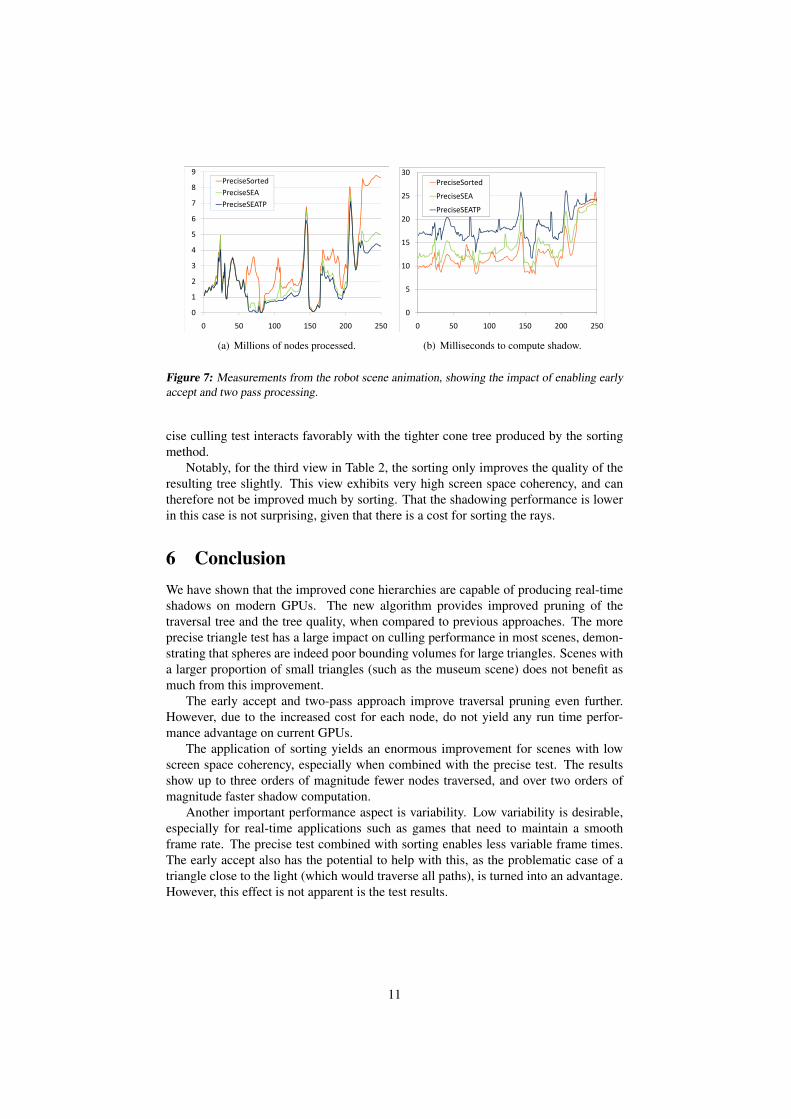
Figure 7 details performance figures using early accept and the two-pass approach.
We show graphs for the sorted varieties only, and using the precise triangle test, as the
differences are similar for the other variations. Notice that the number of nodes culled
is steadily improved with each new optimization, but that the time to compute shadow
is almost the reverse. This is because of the more complicated test, but also because
that the compaction step in the breadth first traversal must be replaced with a more
expensive split operation, which is needed to filter out the elements that are finished.
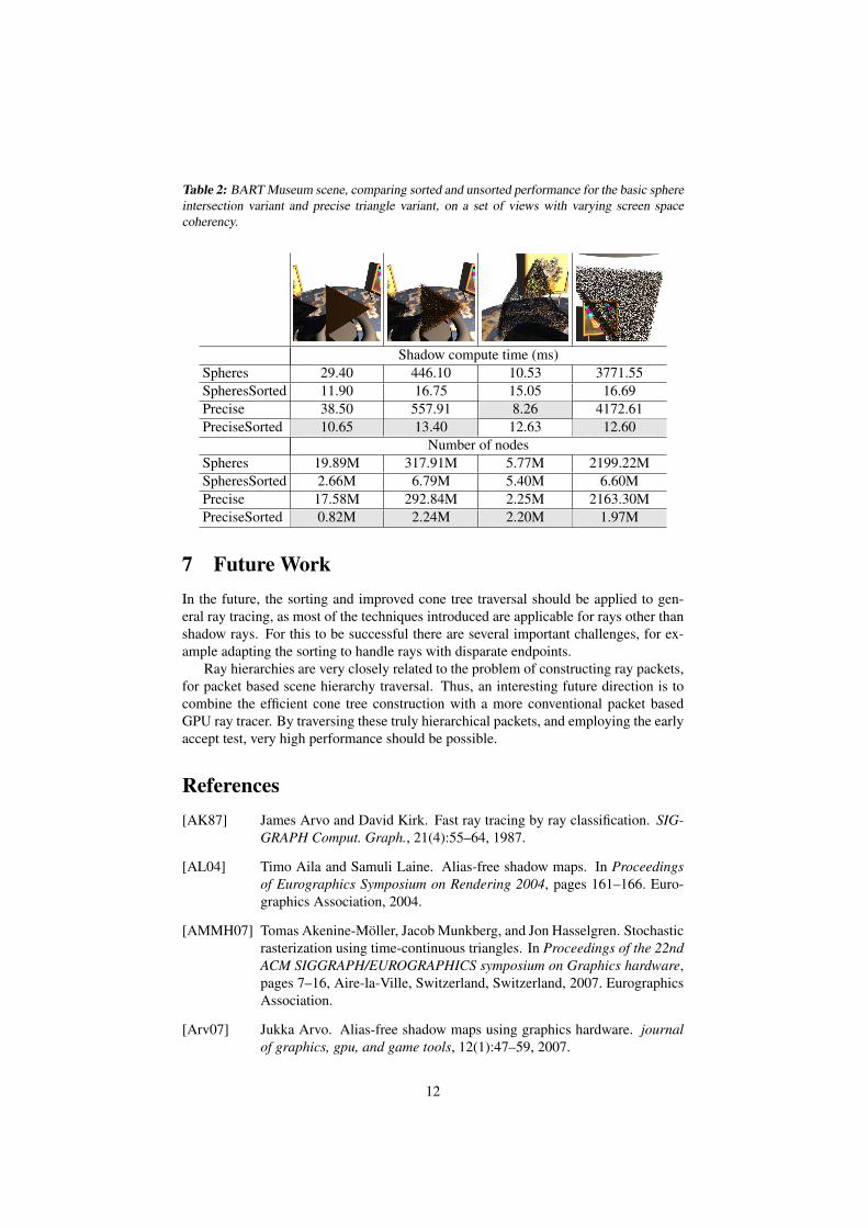
To further investigate the effect of screen space coherency, we used the museum
scene, see Table 2. This scene contains a large quantity of small triangles that are
independently animated.
For this scene, contrary to what we saw for the robots scene (Figure 6), the un-
sorted spheres method often offers better performance than the unsorted precise trian-
gle method. This is because the majority of the shadow casters are very small, which
means that they reasonably well approximated by bounding spheres (see Section 3.2).
The precise version still prunes more nodes, but not sufficiently to compensate for the
more expensive precise triangle test. When sorting is used, however, the performance
gap increases, and the precise method is faster in all views. This shows that the pre-
10
3
4
5
6
7
8
9
PreciseSorted
PreciseSEA
PreciseSEATP
0
1
2
3
4
5
6
7
8
9
0 50 100 150 200 250
PreciseSorted
PreciseSEA
PreciseSEATP
(a) Millions of nodes processed.
10
15
20
25
30
PreciseSorted
PreciseSEA
PreciseSEATP
0
5
10
15
20
25
30
0 50 100 150 200 250
PreciseSorted
PreciseSEA
PreciseSEATP
(b) Milliseconds to compute shadow.
Figure 7: Measurements from the robot scene animation, showing the impact of enabling early
accept and two pass processing.
cise culling test interacts favorably with the tighter cone tree produced by the sorting
method.
Notably, for the third view in Table 2, the sorting only improves the quality of the
resulting tree slightly. This view exhibits very high screen space coherency, and can
therefore not be improved much by sorting. That the shadowing performance is lower
in this case is not surprising, given that there is a cost for sorting the rays.
6 Conclusion
We have shown that the improved cone hierarchies are capable of producing real-time
shadows on modern GPUs. The new algorithm provides improved pruning of the
traversal tree and the tree quality, when compared to previous approaches. The more
precise triangle test has a large impact on culling performance in most scenes, demon-
strating that spheres are indeed poor bounding volumes for large triangles. Scenes with
a larger proportion of small triangles (such as the museum scene) does not benefit as
much from this improvement.
The early accept and two-pass approach improve traversal pruning even further.
However, due to the increased cost for each node, do not yield any run time perfor-
mance advantage on current GPUs.
The application of sorting yields an enormous improvement for scenes with low
screen space coherency, especially when combined with the precise test. The results
show up to three orders of magnitude fewer nodes traversed, and over two orders of
magnitude faster shadow computation.
Another important performance aspect is variability. Low variability is desirable,
especially for real-time applications such as games that need to maintain a smooth
frame rate. The precise test combined with sorting enables less variable frame times.
The early accept also has the potential to help with this, as the problematic case of a
triangle close to the light (which would traverse all paths), is turned into an advantage.
However, this effect is not apparent is the test results.
11
Table 2: BART Museum scene, comparing sorted and unsorted performance for the basic sphere
intersection variant and precise triangle variant, on a set of views with varying screen space
coherency.
Shadow compute time (ms)
Spheres 29.40 446.10 10.53 3771.55
SpheresSorted 11.90 16.75 15.05 16.69
Precise 38.50 557.91 8.26 4172.61
PreciseSorted 10.65 13.40 12.63 12.60
Number of nodes
Spheres 19.89M 317.91M 5.77M 2199.22M
SpheresSorted 2.66M 6.79M 5.40M 6.60M
Precise 17.58M 292.84M 2.25M 2163.30M
PreciseSorted 0.82M 2.24M 2.20M 1.97M
7 Future Work
In the future, the sorting and improved cone tree traversal should be applied to gen-
eral ray tracing, as most of the techniques introduced are applicable for rays other than
shadow rays. For this to be successful there are several important challenges, for ex-
ample adapting the sorting to handle rays with disparate endpoints.
Ray hierarchies are very closely related to the problem of constructing ray packets,
for packet based scene hierarchy traversal. Thus, an interesting future direction is to
combine the efficient cone tree construction with a more conventional packet based
GPU ray tracer. By traversing these truly hierarchical packets, and employing the early
accept test, very high performance should be possible.
References
[AK87] James Arvo and David Kirk. Fast ray tracing by ray classification. SIG-
GRAPH Comput. Graph., 21(4):55–64, 1987.
[AL04] Timo Aila and Samuli Laine. Alias-free shadow maps. In Proceedings
of Eurographics Symposium on Rendering 2004, pages 161–166. Euro-
graphics Association, 2004.
[AMMH07] Tomas Akenine-Moller, Jacob Munkberg, and Jon Hasselgren. Stochastic
rasterization using time-continuous triangles. In Proceedings of the 22nd
ACM SIGGRAPH/EUROGRAPHICS symposium on Graphics hardware,