24
Improved Speed Control Made Simple Stepper Motors CVK Series SC Type

Improved Speed Control Made Simple
Stepper Motors
CVK Series
SC Type
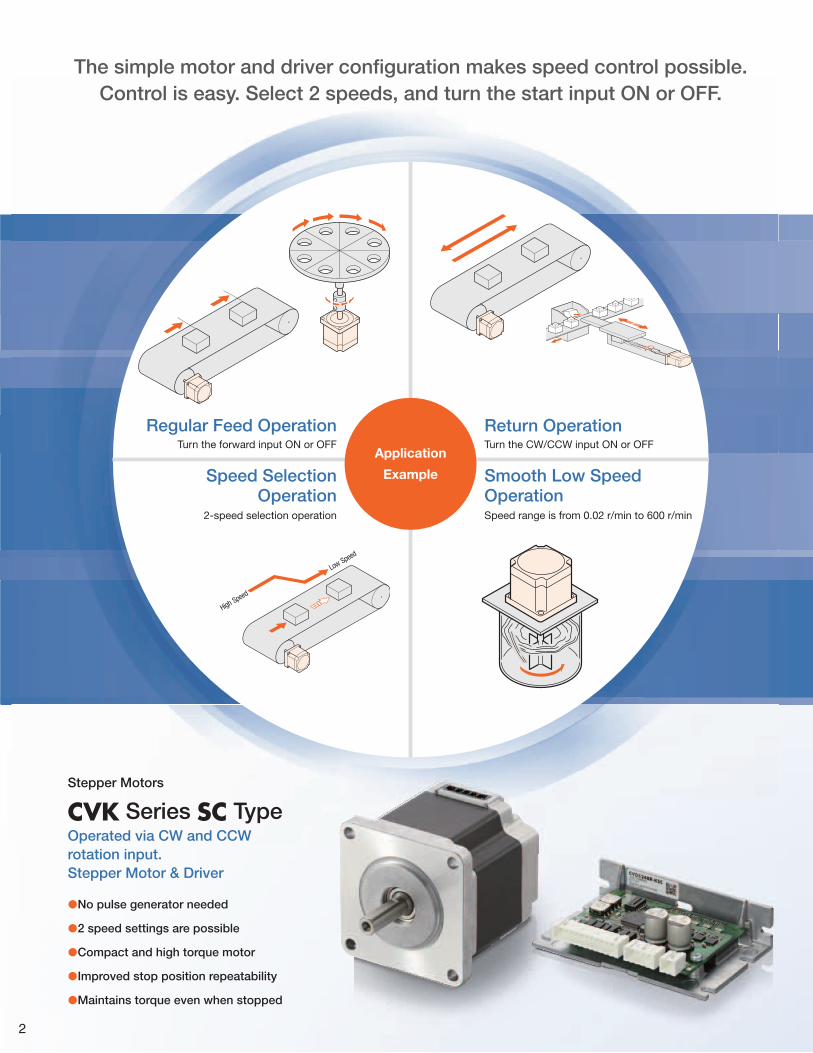
The simple motor and driver confi guration makes speed control possible.Control is easy. Select 2 speeds, and turn the start input ON or OFF.
Application
Example
Regular Feed Operation
Speed Selection Operation
Return Operation
Smooth Low Speed Operation
Turn the forward input ON or OFF
2-speed selection operation
Turn the CW/CCW input ON or OFF
Speed range is from 0.02 r/min to 600 r/min
Low Speed
High Speed
Stepper Motors
CVK Series SC TypeOperated via CW and CCW rotation input.Stepper Motor & Driver
●No pulse generator needed
●2 speed settings are possible
●Compact and high torque motor
●Improved stop position repeatability
●Maintains torque even when stopped
2

Speed Control
Product-Line
Simple System Confi guration to Control I/OSimple configuration consisting of motor, driver and programmable controller. The operating speed, acceleration and deceleration time, running current can be set via the driver switches. Simply turn the FWD (RVS) input to ON or OFF allows for easy control.
2 Individual Speed Setting are PossibleThe driver can be set to 2 individual speeds, and can be easily controlled externally.
Driver2 types of drivers are available.
Motor18 motor models in 3 frame sizes are available.
Maintains Torque When StoppedMotor current is supplied when stopped so torque is still generated. This provides load holding capability (holding force is 50% of max. holding torque).
When the Operation Input is Constant, Stop Position Repeatability is ImprovedWhen the motor is stopped, even if the load weight is changed, if the operating conditions are the same the deceleration traveling amount does not change due to inertial load or frictional load. This allows for improvement of the stop position repeatability.
▪ With installation plate Right Angle TypeThe connector points outward.
◾Return operation ◾2-speed selection operation
▪ With installation plateThe connector points upward.
Speed 2
Speed 1
FWD Input
RVS Input
M0 Input
Speed 1
Speed 2
FWD Input
RVS Input
M0 Input
Speed
FWD Input
Accurate deceleration at the set deceleration rate
Stops without any variation due to load
Operation Input OFF
Constant overrun amount
Switch or Programmable
Controller
24 VDC Power Supply
Motor Driver
28 mm (1.10 in.)
0.052 to 0.091(7.3 to 12.9)
42 mm (1.65 in.)
0.22 to 0.5(31 to 71)
60 mm (2.36 in.)
0.66 to 2.1(93 to 290)
85 (W)×24.5 (H)×57.5 (D)(3.35) (3.35)(0.96) (0.96)(2.26) (2.07)
85 (W)×24.5 (H)×52.5 (D)
Frame size
Maximum Holding Torque N·m (oz-in) Dimensions mm (in.)
The Motor can be Downsized Thanks to the Use of Compact, High Torque MotorsBecause a stepper motor provides high torque at low operation speeds, it can be used without a gearhead. This allows for downsizing of the motor and decreasing the overall size of the equipment as compared to induction motors with almost identical speeds
59(2.32)
131(5.16)
42(1.65)
42(1
.65)
80(3
.14)
80(3.14)
PKP546N18A2Mass: 0.49 kg (1.08 lb.)
Torque: 0.5 N·m
Mass: 2.45 kg (5.4 lb.)
Torque: 0.39 N·m
Induction Motor
CVK Series SC Type
Output 25 W, Gear Ratio 3
Motor dimensions Unit = mm (in.)
3

■System Configuration
This is an example of a system configuration with the programmable controller. Motors, cables and drivers need to be ordered individually.
Programmable
Controller✽
DriverConnection CableMotor
A Connection Cable is required.
24 VDC
Power Supply✽
Motor Mounting Bracket
Accessories (Sold Separately)
✽Not Supplied.
CVK Series SC Type
MCV Coupling
➜ Page 22 ➜ Page 21
Connection Cable ➜ Page 18
Cable for I/O Signals Cable for DC Power Supply
Driver Connection Cables
➜ Page 20 ➜ Page 20
●Example System Confi guration Price
CVK Series SC Type Accesssories
MotorConnection
Cable (5 m)Driver
+
Motor
Mounting BracketFlexible Coupling
PKP566FN24A2 CCM050V5AEF CVD524BR-KSC PAL2P-5 MCV190808$75.00 $41.00 $188.00 $17.00 $72.00
● The system configuration shown above is an example. Other combinations are also available.
4

■Product Number
●Motor
PKP 5 6 6 F N 24 A 2① ② ③ ④ ⑤ ⑥ ⑦ ⑧ ⑨
① Series Name PKP: PKP Series② 5: 5-Phase
③Motor Frame Size 2: 28 mm (1.10 in.) 4: 42 mm (1.65 in.)
6: 56.4 mm (2.22 in.)60 mm (2.36 in.) when the Motor Identifi cation is F
④ Motor Case Length⑤ Motor Identifi cation F: Motor Frame Size 60 mm (2.36 in.)⑥ Number of Lead Wires N: 5⑦ Motor Winding Specifi cation⑧ Shaft A: Single Shaft B: Double Shaft⑨ Reference Number
●Driver
CVD 5 18 B R - K SC① ② ③ ④ ⑤ ⑥ ⑦
① Driver Type CVD: CVK Series Driver② 5: 5-Phase③ Rated Current④ Driver Shape B: with Installation Plate⑤ Connector Shape R: Right Angle⑥ Power Supply Input K: DC Power Supply⑦ Driver Type SC: Speed Control
■Product Line
Please purchase motor, driver and connection cables separately.
●MotorProduct Name (Single Shaft) List Price Product Name (Double Shaft) List Price
PKP523N12APKP525N12A
$64.00$74.00
PKP523N12BPKP525N12B
$66.00$75.00
PKP543N18A2PKP544N18A2PKP545N18A2PKP546N18A2
$52.00$54.00$61.00$66.00
PKP543N18B2PKP544N18B2PKP545N18B2PKP546N18B2
$54.00$56.00$64.00$69.00
PKP564FN24A2PKP566FN24A2PKP569FN24A2
$69.00$75.00$92.00
PKP564FN24B2PKP566FN24B2PKP569FN24B2
$72.00$78.00$95.00
●Driver ◇Right Angle Type with Installation Plate ◇With Installation Plate
Product Name List PriceCVD512BR-KSC
$188.00CVD518BR-KSCCVD524BR-KSC
Product Name List PriceCVD512B-KSC
$188.00CVD518B-KSCCVD524B-KSC
●Connection CableCables for connecting the motor and driver and cables to connect the driver to the programmable controller are available.Refer to page 17 for details.
■Included Items
●MotorIncluded
Operating ManualType
Common to All Types 1 Copy
●DriverIncluded
Connector Operating ManualType
Common to All TypesConnector fot CN1 1pc.Connector fot CN2 1pc.Connector fot CN3 1pc.
1 Set
5

■Explanation of Specifications Table Terminology
Max. Holding Torque : This is the maximum holding force the motor has when power is supplied (at rated current) but the motor is not rotating.
Holding Torque While Stopped : This is holding torque when the automatic current cutback function is active.
Setting Speed Range : This is the settable speed range for the motor and driver combination.
Speed Accuracy : Degree of operating speed errors due to individual differences, temperature and deterioration due to age of the driver.
Frame Size 28 mm (1.10 in.)5-Phase Stepper Motors
■Specifications
Motor Product NameSingle Shaft PKP523N12A PKP525N12ADouble Shaft PKP523N12B PKP525N12B
Driver Product Name CVD512B□-KSC CVD512B□-KSCMaximum Holding Torque N·m (oz-in) 0.052 (7.3) 0.091 (12.9)Holding Torque at Motor Standstill N·m (oz-in) 0.026 (3.6) 0.045 (6.3)Rotor Inertia J: kg·m2 (oz-in2) 9×10⁻⁷ (0.049) 18×10-7 (0.099)Rated Current A/Phase 1.2Setting speed range r/min 0.02 to 600Speed accuracy✽ ±0.8%Power Supply Input 24 VDC±10% 0.9 AExcitation Mode Microstep
●For the right angle type with an installation plate, an R (right angle) indicating the connector configuration is specified where the box □ is located in the product name.
✽The actual operating speed is accurate within ±0.8% against the set speed.
■Speed – Torque Characteristics (Reference values)
PKP523 PKP525
00
0.020.5
0.04
0.06
0.08
0 100 200 300 400 500 600 700
1.0
2
4
6
8
0
10
Torq
ue [ N
·m]
Curr
ent [
A] Torq
ue [o
z-in
]
Speed [r/min]
Driver Input Current
Pullout Torque
Operating Current Rate 100%Operating Current Rate 70%
Driver: CVD512BR-KSC Power Supply Voltage: 24 VDCCurrent: 1.2 A/Phase
00
0.020.5
0.041.0
0.06
0.08
0.10
0.12
0 100 200 300 400 500 600 700
2
4
6
8
12
10
0
16
14
Torq
ue [ N
·m]
Curr
ent [
A]
Speed [r/min]
Pullout Torque
Driver Input Current
Driver: CVD512BR-KSC Power Supply Voltage: 24 VDCCurrent: 1.2 A/Phase
Operating Current Rate 100%Operating Current Rate 70%
Torq
ue [o
z-in
]
Note ●Data for the speed - torque characteristics is based on Oriental Motor's internal measurement conditions. If the conditions are changed, the characteristics may also change as a result. ●Depending on the driving conditions, a considerable amount of heat may be generated by the motor. Be sure to keep the motor case temperature at 100˚C (212˚F), or less.
6

Frame Size 42 mm (1.65 in.)5-Phase Stepper Motors
■Specifications
Motor Product NameSingle Shaft PKP543N18A2 PKP544N18A2 PKP545N18A2 PKP546N18A2Double Shaft PKP543N18B2 PKP544N18B2 PKP545N18B2 PKP546N18B2
Driver Product Name CVD518B□-KSC CVD518B□-KSC CVD518B□-KSC CVD518B□-KSCMaximum Holding Torque N·m (oz-in) 0.22 (31) 0.3 (42) 0.37 (52) 0.5 (71)Holding Torque at Motor Standstill N·m (oz-in) 0.11 (15.6) 0.15 (21) 0.19 (26) 0.25 (35)Rotor Inertia J: kg·m2 (oz-in2) 35×10-7 (0.192) 55×10-7 (0.3) 71×10-7 (0.39) 110×10-7 (0.6)Rated Current A/Phase 1.8Setting speed range r/min 0.02 to 600Speed accuracy✽ ±0.8%Power Supply Input 24 VDC±10% 2.5 AExcitation Mode Microstep
●For the right angle type with an installation plate, an R (right angle) indicating the connector configuration is specified where the box □ is located in the product name.
✽The actual operating speed is accurate within ±0.8% against the set speed.
■Speed – Torque Characteristics (Reference values)
PKP543 PKP544
00
1
0.12
0.2
0.3
0 100 200 300 400 500 600 700
10
20
30
0
40
Torq
ue [ N
·m]
Curr
ent [
A]
Torq
ue [o
z-in
]
Speed [r/min]
Driver: CVD518BR-KSC Power Supply Voltage: 24 VDCCurrent: 1.8 A/Phase
Pullout Torque
Driver Input Current
Operating Current Rate 100%Operating Current Rate 70%
00
1
0.12
0.2
0.3
0.4
0 100 200 300 400 500 600 700
10
20
40
30
0
50
Torq
ue [ N
·m]
Curr
ent [
A]
Speed [r/min]
Driver: CVD518BR-KSC Power Supply Voltage: 24 VDCCurrent: 1.8 A/Phase
Pullout Torque
Driver Input Current
Operating Current Rate 100%Operating Current Rate 70%
Torq
ue [o
z-in
]
PKP545 PKP546
00
0.12
0.24
10
20
30
40
50
60
0
70
0.3
0.4
0.5
0 100 200 300 400 500 600 700
Torq
ue [ N
·m]
Curr
ent [
A]
Torq
ue [o
z-in
]
Speed [r/min]
Driver: CVD518BR-KSC Power Supply Voltage: 24 VDCCurrent: 1.8 A/Phase
Pullout Torque
Driver Input Current
Operating Current Rate 100%Operating Current Rate 70%
00
0.11
0.22
0.33
20
40
60
80
0
0.4
0.5
0.6
0.7
0 100 200 300 400 500 600 700
Torq
ue [ N
·m]
Curr
ent [
A] Torq
ue [o
z-in
]
Speed [r/min]
Driver: CVD518BR-KSC Power Supply Voltage: 24 VDCCurrent: 1.8 A/Phase
Pullout Torque
Driver Input Current
Operating Current Rate 100%Operating Current Rate 70%
Note ●Data for the speed - torque characteristics is based on Oriental Motor's internal measurement conditions. If the conditions are changed, the characteristics may also change as a result. ●Depending on the driving conditions, a considerable amount of heat may be generated by the motor. Be sure to keep the motor case temperature at 100˚C (212˚F), or less.
7

Frame Size 60 mm (2.36 in.)5-Phase Stepper Motors
■Specifications
Motor Product NameSingle Shaft PKP564FN24A2 PKP566FN24A2 PKP569FN24A2Double Shaft PKP564FN24B2 PKP566FN24B2 PKP569FN24B2
Driver Product Name CVD524B□-KSC CVD524B□-KSC CVD524B□-KSCMaximum Holding Torque N·m (oz-in) 0.66 (93) 1.15 (163) 2.1 (290)Holding Torque at Motor Standstill N·m (oz-in) 0.33 (46) 0.58 (82) 1.1 (156)Rotor Inertia J: kg·m2 (oz-in2) 160×10-7 (0.88) 290×10-7 (1.59) 540×10-7 (3.0)Rated Current A/Phase 2.4Setting speed range r/min 0.02 to 600Speed accuracy✽ ±0.8%Power Supply Input 24 VDC±10% 3.0 AExcitation Mode Microstep
●For the right angle type with an installation plate, an R (right angle) indicating the connector configuration is specified where the box □ is located in the product name.
✽The actual operating speed is accurate within ±0.8% against the set speed.
■Speed – Torque Characteristics (Reference values)
PKP564F PKP566F PKP569F
0
0.2
0.4
0.6
0.8
1.0
0 100 200 300 400 500 600 7000
2
4
20
40
60
80
100
0
120
140
Torq
ue [ N
·m]
Speed [r/min]
Driver: CVD524BR-KSC Power Supply Voltage: 24 VDCCurrent: 2.4 A/Phase
Driver Input Current
Pullout Torque
Curr
ent [
A]
Operating Current Rate 100%Operating Current Rate 70%
Torq
ue [o
z-in
]
00
0.22
0.44
0.6
0.8
1.0
1.2
1.4
1.6
0 100 200 300 400 500 600 700
50
100
150
0
200
Torq
ue [ N
·m]
Curr
ent [
A]
Speed [r/min]
Driver: CVD524BR-KSC Power Supply Voltage: 24 VDCCurrent: 2.4 A/Phase
Driver Input Current
Pullout Torque
Operating Current Rate 100%Operating Current Rate 70%
Torq
ue [o
z-in
]
00
0.54
1.08
1.5
2.0
2.5
3.0
0 100 200 300 400 500 600 700
100
200
300
0
400
Torq
ue [ N
·m]
Curr
ent [
A]
Speed [r/min]
Driver: CVD524BR-KSC Power Supply Voltage: 24 VDCCurrent: 2.4 A/Phase
Pullout Torque
Driver Input Current
Operating Current Rate 100%Operating Current Rate 70%
Torq
ue [o
z-in
]
Note ●Data for the speed - torque characteristics is based on Oriental Motor's internal measurement conditions. If the conditions are changed, the characteristics may also change as a result. ●Depending on the driving conditions, a considerable amount of heat may be generated by the motor. Be sure to keep the motor case temperature at 100˚C (212˚F), or less.
8

■Driver Specifications
Input Signal
· Photocoupler input (FWD, RVS)Photocoupler [ON]: input voltage 3∼5.25 VDC, Photocoupler [OFF]: input voltage 0∼1 VDC (Terminal voltage)· Photocoupler input (AWO, M0)Photocoupler [ON]: input voltage 4.5∼5.25 VDC, Photocoupler [OFF]: input voltage 0∼1 VDC (Terminal voltage)
Output SignalPhotocoupler and open-collector output,External operating conditions: 30 VDC 10 mA max. (ALM, PLS-OUT)
■General SpecificationsMotor Driver
Thermal Class 130 (B) −
Insulation ResistanceThe measured value is 100 MΩ min. when a 500 VDC megger is applied between the windings and the case under normal ambient temperature and humidity.
−
Dielectric Voltage
No abnormalities are observed, even when applying voltage between the windings and the case for 1 minute under normal ambient temperature and humidity with the following conditions.·PKP52□, PKP54□: 0.5 kVAC 50/60 Hz·PKP56□: 1.0 kVAC 50/60 Hz
−
Operating Environment (In operation)Ambient Temperature −10∼+50˚C (+14∼+122˚F) (Non-freezing) 0∼+50˚C (+32∼+122˚F) (Non-freezing)Ambient Humidity 85% or less (Non-condensing)Atmosphere No corrosive gases or dust. The product should not be exposed to water, oil or other liquids.
Temperature RiseWinding temperature rise 80˚C (176˚F) max.
(Based on Oriental Motor's internal measurement conditions)−
Shaft Runout 0.05T.I.R (mm)✽3 −
Radial Play✽1 0.025 mm (0.001 in.) max. ((5 N load) (1.12 lb.)) −
Axial Play✽2 0.075 mm (0.003 in.) max. ((10 N load) (2.2 lb.))[PKP52□ is 2.5 N load (0.59 lb.)]
−
Concentricity of Installation Pilot to the Shaft 0.075T.I.R mm (0.003 in.)✽3 −
Perpendicularity of Installation Surface to the Shaft 0.075T.I.R mm (0.003 in.)✽3 −
✽1 Radial Play: Displacement in shaft position in the radial direction when a 5 N (1.12 lb.) load is applied perpendicular to the tip of the motor shaft.
✽2 Axial Play: Displacement in shaft position in the axial direction when a 10 N (2.2 lb.) (PKP52□ is 2.5 N (0.59 lb.)) load is applied to the motor shaft in the axial direction.
✽3 T. I. R. (Total Indicator Reading): The total dial gauge reading when the measurement section is rotated once around the reference axis center.Note
●When performing insulation resistance measurement or dielectric strength, please disconnect the motor and driver.
A
A0.075
Aϕ0.075
0.05
■Rotation DirectionThis indicates the rotation direction when viewed from the output shaft side of the motor. When driver FWD input is ON: CW directionWhen driver RVS input is ON: CCW direction
●Motor
Counterclockwise RotationCCW
Clockwise RotationCW
■Permissible Radial Load and Permissible Axial LoadUnit: N (lb.)
MotorFrame Size
Product NamePermissible Radial Load
Permissible Axial Load
Dinstance from Shaft End mm [in.]0 [0] 5 [0.2] 10 [0.39] 15 [0.59] 20 [0.79]
28 mm [1.10 in.] PKP523, PKP525 25 (5.6) 34 (7.6) 52 (11.7) − − 5 (1.12)
42 mm [1.65 in.]PKP543, PKP544PKP545, PKP546 35 (7.8) 44 (9.9) 58 (13) 85 (19.1) − 15 (3.3)
60 mm [2.36 in.] PKP564, PKP566, PKP569 90 (20) 100 (22) 130 (29) 180 (40) 270 (60) 30 (6.7)
●Radial Load and Axial Load
15 (0.59)
5 (0.2)10 (0.39)
20 (0.79)
Distance from Shaft End [mm (in.)]
Axial Load
Radial Load
9

■Dimensions Unit = mm (in.)
●MotorFrame Size 28 mm (1.10 in.)
Product Name L1 L2Mass
kg (lb.)2D CAD
PKP523N12A 32(1.26)
− 0.11(0.24)
B1146PKP523N12B 42 (1.65)PKP525N12A 51.5
(2.03)− 0.2
(0.44)B1147
PKP525N12B 61.5 (2.42)
●Connection Cable (Sold separately)Product Name: LC5N06A
5 ( 0
.2)
L11.5 (0.06)
L2
9.5 (0.37)
ϕ22
−0.
033
( ϕ0.
8661
−0.
0013
)0
ϕ5 −
0.01
2 ( ϕ
0.19
69−
0.00
05)
0
ϕ5 −
0.01
2 ( ϕ
0.19
69−
0.00
05)
0
5 1
16.5 (0.65)
28 (1.10)
28 ( 1
.10)
✽10±1
(0.39±0.04)
15±1(0.59±0.04)
10±0.25(0.394±0.010)
4.5±
0.15
( 0.1
77±
0.00
6)
4.5±
0.15
( 0.1
77±
0.00
6)
23±0.2(0.906±0.008)
23±
0.2
( 0.9
06±
0.00
8)
0
0
0
4×M2.5×2.5 (0.10) Deep
✽The length of the shaft flat on the double shaft model is 10±0.25 (0.394±0.010).
Frame Size 42 mm (1.65 in.)
Product Name L1 L2Mass
kg (lb.)2D CAD
PKP543N18A2 33(1.30)
− 0.23(0.51)
B1264PKP543N18B2 48 (1.89)PKP544N18A2 39
(1.54)− 0.29
(0.64)B1265
PKP544N18B2 54 (2.13)PKP545N18A2 47
(1.85)− 0.37
(0.81)B1266
PKP545N18B2 62 (2.44)PKP546N18A2 59
(2.32)− 0.49
(1.08)B1267
PKP546N18B2 74 (2.91)
●Connection Cable (Sold separately)Product Name: LC5N06E
511.5 (0.06)
3 (0.
12)
5.9 (0.23)
L1L2
9.7 (0.38)2.7 (0.10)
25(0.98)
23(0.91)[ 6
( 0.2
4)]✽
2
00
ϕ5 −
0.01
2 ( ϕ
0.19
69−
0.00
05)
4.5±
0.15
( 0.1
77±
0.00
6)
15±1✽1
(0.591±0.04)
20±0.5 (0.79±0.02)15±0.25 (0.591±0.01)
42 (1.65)
42 ( 1
.65)
31±0.2 (1.22±0.008)
31±
0.2
( 1.2
2±0.
008)
4.5±
0.15
( 0.1
77±
0.00
6)0
0 0
ϕ5 −
0.01
2 ( ϕ
0.19
69−
0.00
05)
ϕ22
−0.
021
( ϕ0.
8661
−0.
0008
)0
4×M3×4.5 (0.177) Deep
✽1 The length of the shaft flat on the double shaft model is 15±0.25 (0.591±0.010).
✽2 With connection cable
Frame Size 60 mm (2.36 in.)
Product Name L1 L2Mass
kg (lb.)2D CAD
PKP564FN24A2 44(1.73)
− 0.56(1.23)
B1252PKP564FN24B2 65 (2.56)PKP566FN24A2 56
(2.20)− 0.79
(1.74)B1253
PKP566FN24B2 77 (3.03)PKP569FN24A2 84.5
(3.33)− 1.3
(2.9)B1254
PKP569FN24B2 105.5 (4.15)
●Connection Cable (Sold separately)Product Name: LC5N06E
2 (0.
08)
5.9 (0.23)13.5 (0.53)
5.5 (0.21)
60 ( 2
.36)
60 (2.36)
[ 5 ( 0
.20)
]✽
7 (0.28)
2 (0.08)
0ϕ
8 −0.
015
( ϕ0.
3150
−0.
0006
)
0ϕ
8 −0.
015
( ϕ0.
3150
−0.
0006
)
7.5±
0.15
( 0.2
95±
0.00
6)
20±0.25 (0.787±0.010)21±1 (0.83±0.04)
24±0.5 (0.94±0.02)20±0.25 (0.787±0.010)
7.5±
0.15
( 0.2
95±
0.00
6)
00
ϕ36
−0.
025
( ϕ1.
4173
−0.
0010
)
50±0.35(1.969±0.014)
50±
0.35
( 1.9
69±
0.01
4)L1
L2
1 5
0
0
26(1.02)
23(0.91)
4×ϕ4.5 (0.177) Thru
✽With connection cable
●Applicable ConnectorsThe table below shows the applicable connectors.
◇MotorFrame Size Connector Housing Contact Cimpring Tool Manufacturer Name
28 mm (1.10) 51065-0500 50212-8100 57176-5000 Molex42 mm (1.65), 60 mm (2.36) MDF97-5S-3.5C MDF97-22SC HT801/MDF97-22S HIROSE ELECTRIC CO.,LTD
●These dimensions are for double shaft motors. For single shaft motors, ignore the shaft in the areas.
10

●Driver ◇Right Angle Type with Installation Plate
Product Name Mass kg (oz.) 2D CADCVD512BR-KSC
0.06 (2.1) B1210CVD518BR-KSCCVD524BR-KSC ● Included
Connector Housing: 51103-0200 (Molex)
51103-0500 (Molex)
51103-1200 (Molex)
Contact: 50351-8100 (Molex)
3.5
( 0.1
4)3.
5( 0
.14)
5 ( 0
.20)
30 ( 1
.18)
52.5
( 2.0
7)
3.5 (0.14) 78 (3.07)85 (3.35)
2.5
( 0.1
0)
20 (0.79)
2 (0.08)
3.5(0.14)
78 (3.07)
3.5
( 0.1
4)
8 ( 0
.31)
24.5 (0.96) max.
5 ( 0
.20)
max
. 1 12 1 5 1 2
◇With Installation Plate
Product Name Mass kg (oz.) 2D CADCVD512B-KSC
0.06 (2.1) B1255CVD518B-KSCCVD524B-KSC ● Included
Connector Housing: 51103-0200 (Molex)
51103-0500 (Molex)
51103-1200 (Molex)
Contact: 50351-8100 (Molex)
2.5
( 0.1
0)
20 (0.79)
2 (0.08)
24.5 (0.96) max.3.5 (0.14) 78 (3.07)
85 (3.35)
3.5
( 0.1
4)3.
5( 0
.14)
5 ( 0
.20)
30 ( 1
.18)
52.5
( 2.0
7)
1 12 1 5 1 2
3.5(0.14)
78 (3.07)
3.5
( 0.1
4)
8 ( 0
.31)
11
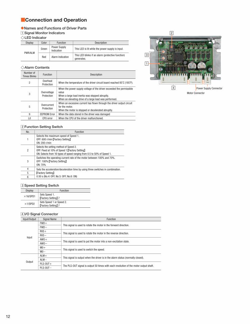
■Connection and Operation
●Names and Functions of Driver Parts Signal Monitor Indicators ◇LED Indicator
Display Color Function Description
PWR/ALMGreen
Power Supply Indication
This LED is lit while the power supply is input.
Red Alarm IndicationThis LED blinks if an alarm (protective function) generates.
◇Alarm Contents
Number of Times Blinks
Function Description
2Overheat Protection
When the temperature of the driver circuit board reached 85˚C (185˚F).
3Overvoltage Protection
When the power supply voltage of the driver exceeded the permissible valueWhen a large load inertia was stopped abruptly.When an elevating drive of a large load was performed.
5Overcurrent Protection
When an excessive current has fl own through the driver output circuit for the motor.When the motor is stopped or decelerated abruptly.
9 EEPROM Error When the data stored in the driver was damagedLit CPU error When the CPU of the driver malfunctioned.
1
2
4
3
Motor Connector
Power Supply Connector
Function Setting SwitchNo. Function
1Selects the maximum speed of Speed 1. OFF: 600 r/min Factory SettingON: 200 r/min
2Selects the setting method of Speed 2. OFF: Fixed at 10% of Speed 1 Factory SettingON: Selects from 16 types of speed ranging from 0.5 to 50% of Speed 1.
3Switches the operating current rate of the motor between 100% and 70%. OFF: 100% Factory SettingON: 70%
4 Sets the acceleration/deceleration time by using three switches in combination. Factory Setting
0.50 s (No.4: OFF, No.5: OFF, No.6: ON)56
Speed Setting SwitchDisplay Function
×16/SPD1Sets Speed 1. Factory Setting 7
×1/SPD2Sets Speed 1 or Speed 2. Factory Setting 7
I/O Signal ConnectorInput/Output Signal Name Function
Input
FWD+This signal is used to rotate the motor in the forward direction.
FWD−RVS+
This signal is used to rotate the motor in the reverse direction.RVS−AWO+
This signal is used to put the motor into a non-excitation state.AWO−M0+
This signal is used to switch the speed.M0−
Output
ALM+This signal is output when the driver is in the alarm status (normally closed).
ALM−
PLS-OUT+The PLS-OUT signal is output 50 times with each revolution of the motor output shaft.
PLS-OUT−
12

●Connection Diagrams ◇When input-signal voltage is 5 VDC
R0
0 V
0 V
0 V
GND
24 VDC±10%
FWD
RVS
AWO
ALM
CN3
CN3
CN1
5
4
3
2
1
4
3
2
1
10
9
R0
PLS-OUT12
11
6
5
−
+
CN2
100 Ω
100 Ω
100 Ω
100 Ω
470 Ω
2.2 kΩ
2.2 kΩ
2.2 kΩ
2.2 kΩ
1 kΩ
M08
7470 Ω
1 kΩ
0 V
5 VDC
5 VDC
Output Saturated Voltage 0.5 V Max.
Driver
RedBlue
Motor LeadWires✽
Twisted-Pair Wire
GreenBlack
Orange
Current Sink Output CircuitCurrent Source Output Circuit
Programmable Controller
30 VDC Max.
30 VDC Max.
10 mA Max.➞
✽Connector pin arrangement is different depending on the motor, please check the connection table below for details.
◇Motor and Driver Connection TableModel A
5 1Pin No.�
Model B
1 5Pin No.�
DriverCN2 Pin No.
Model A Model BPin No. Color Pin No. Color
1 5 Blue 1 Blue2 4 Red 2 Red3 3 Orange 3 Orange4 2 Green 4 Green5 1 Black 5 Black
●The “Color” in the table indicates the lead wire color of the connection cable sold separately.Note
●The pin arrangement for Model A and Model B motors is different. Normal rotation may not occur if connected improperly.
13
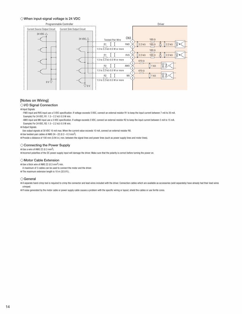
◇When input-signal voltage is 24 VDC
R2
0 V
0 V
FWD
RVS
AWO
CN3
4
3
2
1
6
5
100 Ω
100 Ω
100 Ω
100 Ω
470 Ω
2.2 kΩ
2.2 kΩ
2.2 kΩ
2.2 kΩ
1 kΩ
R2
R1
1.5 to 2.2 kΩ 0.5 W or more
1.5 to 2.2 kΩ 0.5 W or more
1.5 to 2.2 kΩ 0.5 W or more
1.5 to 2.2 kΩ 0.5 W or more
R1
M08
7470 Ω
1 kΩ
24 VDC
24 VDC
Driver
Twisted-Pair Wire
Current Sink Output CircuitCurrent Source Output Circuit
Programmable Controller
[Notes on Wiring] ◇I/O Signal Connection
● Input Signals· FWD input and RVS input use a 5 VDC specification. If voltage exceeds 5 VDC, connect an external resistor R1 to keep the input current between 7 mA to 20 mA. Example) For 24 VDC, R1: 1.5∼2.2 kΩ 0.5 W min.· AWO input and M0 input use a 5 VDC specification. If voltage exceeds 5 VDC, connect an external resistor R2 to keep the input current between 5 mA to 15 mA. Example) For 24 VDC, R2: 1.5∼2.2 kΩ 0.5 W min. ●Output SignalsUse output signals at 30 VDC 10 mA max. When the current value exceeds 10 mA, connect an external resistor R0. ●Use twisted-pair cables of AWG 24∼22 (0.2∼0.3 mm2). ●Provide a distance of 100 mm (3.94 in.) min. between the signal lines and power lines (such as power supply lines and motor lines).
◇Connecting the Power Supply ●Use a wire of AWG 22 (0.3 mm2). ● Incorrect polarities of the DC power-supply input will damage the driver. Make sure that the polarity is correct before turning the power on.
◇Motor Cable Extension ●Use a thick wire of AWG 22 (0.3 mm2) min. A maximum of 3 cables can be used to connect the motor and the driver. ●The maximum extension length is 10 m (32.8 ft.).
◇General ●A separate hand crimp tool is required to crimp the connector and lead wires included with the driver. Connection cables which are available as accessories (sold separately) have already had their lead wires crimped. ● If noise generated by the motor cable or power supply cable causes a problem with the specific wiring or layout, shield the cables or use ferrite cores.
14

●Speed Setting Method
×16/SPD1 Switch
[Function Setting Switch]No.1: SPD H/L Switch (Highest Speed)No.2: SPD2 EN Switch (Select Speed 2)No.3: RUN Switch (Operating Current)No.4 to 6: ACC Switch (Acceleration Time, Deceleration Time)
×1/SPD2 Switch
[Speed Setting Switch]
The CVK Series SC Type motors can be set with 2 types of operating speeds, a high speed and low speed. The high speed “Speed 1” and low speed “Speed 2” are defined below. Speed 1....High speed side operating speed when M0 input is OFF. Speed 2... Low speed side operating speed when M0 input is ON.
Speed 1
Speed 2
FWD Input
RVS Input
M0 Input
There are 2 setting patterns for Speed 1 and Speed 2, which varies according to the setting of the SPD2 EN switch (function setting switch No. 2).
SettingPattern
SPD2 ENSwitch
Speed Setting Method Switch to Use
Pattern 1
OFF
Speed 1: Selects the speed from 256 types of speed.
Use ×16/SPD1 and ×1/SPD2
Speed 2:Fixed at 10% of Speed 1
None
Pattern 2
ON
Speed 1: Selects the speed from 16 types of speed
×16/SPD1
Speed 2: Selects the speed from 16 types of speed ranging from 0.5 to 50% of Speed 1.
×1/SPD2
◇Setting Process
➔➔
➔➔
➔
Select the highest speed of of the Speed 1.
Select the setting method of the Speed 2.
Select the operation speed for the Speed 1 and 2.
Set the acceleration time and deceleration time.
Set the operating current rate.
The setting is completed.
◇Setting Item ●Maximum Speed
Select the Speed 1 max. speed using the SPD H/L switch (function setting switch No. 1). The max. speed can be selected from either 200 r/min or 600 r/min. The speed which can be set using the speed setting switch is either 200 r/min or 600 r/min.
OFF: 600 r/min (Factory setting)ON: 200 r/min
●Speed 2 Setting MethodSelect the Speed 2 setting method using the SPD2 EN switch (function setting switch No. 2).
OFF: Speed fixed at 10% of Speed 1 (factory setting)ON: Select 1 speed from 16 types in a range of 0.5 to 50% of Speed 1
●Operating SpeedOperating speed varies according to the setting pattern.
[Pattern]Speed 1··· Check the desired speed setting from the 256 types
in the setting value list and set using a combination of “×16/SPD1 switch” and “×1/SPD2 switch”.
Speed 2···Speed is fixed at 10% of Speed 1.
[Pattern 2]Speed 1··· Check the desired speed setting from the 16 types in the
setting value list and set using a combination of “×16/SPD1 switch”.
Speed 2··· Check the desired speed setting from the 16 types in the setting value list and set using a combination of “×16/SPD2 switch”.
●Acceleration Time and Deceleration TimeAcceleration time is time required for the speed to reach 600 r/min from 0 r/min. Deceleration time is time required for the speed to reach 0 r/min from 600 r/min. The same time is applied to acceleration, deceleration and speed change. Please set using ACC0 to 2 (function setting switch No. 4 to 6).
600
Time[s]
AccelerationTime
DecelationTime
Speed[r/min]
Operation Speed
ACC0 (No.4) ACC1 (No.5) ACC2 (No.6)Acceleration timeDeceleration time
OFF OFF OFF 0.00 sON OFF OFF 0.05 sOFF ON OFF 0.10 sON ON OFF 0.20 sOFF OFF ON 0.50 sON OFF ON 1.00 sOFF ON ON 2.00 sON ON ON 3.00 s
15

●Running Current Ratio and Standstill Current Ratio[Running Current Ratio]When the load is light and there is excess torque, by reducing the running current ratio, temperature rise in the motor can be suppressed. The actual running current is the value derived by multiplying the driver’s rated current by the running current ratio.
Running current=Rated current of driver×Running current ratio
The running current ratio can be selected using the RUN switch (function setting switch No. 3).
OFF: Running current ratio 100% (factory setting) ON: Running current ratio 70%
NoteWhen the optional circuit product cover is installed on the CVD524BR-KSC, please set the running current ratio to 70%.
[Standstill Current Ratio]When the motor is stopped, the current cutback function activates, and the motor current is lowered until the motor fully stops. Standstill current ratio is 50% of the running current.
Standstill Current=Running Current×50%
◇Operating Speed Setting Values ListWhen max. speed is 600 r/min
Pattern 1Speed 1: Selects the speed from 256 types of speed.Speed 2: Fixed at 10% of Speed 1
Pattern 2Speed 1: Selects the speed from 16 types of speedSpeed 2: Selects the speed from 16 types of speed ranging from 0.5 to 50% of Speed 1.
●Pattern 1 Unit: r/min
×1/SPD2 Switch0 1 2 3 4 5 6 7 8 9 A B C D E F
×16
/SPD
1 Sw
itch
0 0.90 1.00 1.10 1.20 1.30 1.40 1.50 1.60 1.70 1.80 1.90 2.00 2.10 2.20 2.30 2.40 1 2.50 5.00 7.50 10.00 12.50 15.00 17.50 20.00 22.50 25.00 27.50 30.00 32.50 35.00 37.50 40.00 2 42.50 45.00 47.50 50.00 52.50 55.00 57.50 60.00 62.50 65.00 67.50 70.00 72.50 75.00 77.50 80.00 3 82.50 85.00 87.50 90.00 92.50 95.00 97.50 100.00 102.50 105.00 107.50 110.00 112.50 115.00 117.50 120.00 4 122.50 125.00 127.50 130.00 132.50 135.00 137.50 140.00 142.50 145.00 147.50 150.00 152.50 155.00 157.50 160.00 5 162.50 165.00 167.50 170.00 172.50 175.00 177.50 180.00 182.50 185.00 187.50 190.00 192.50 195.00 197.50 200.00 6 202.50 205.00 207.50 210.00 212.50 215.00 217.50 220.00 222.50 225.00 227.50 230.00 232.50 235.00 237.50 240.00 7 242.50 245.00 247.50 250.00 252.50 255.00 257.50 260.00 262.50 265.00 267.50 270.00 272.50 275.00 277.50 280.00 8 282.50 285.00 287.50 290.00 292.50 295.00 297.50 300.00 302.50 305.00 307.50 310.00 312.50 315.00 317.50 320.00 9 322.50 325.00 327.50 330.00 332.50 335.00 337.50 340.00 342.50 345.00 347.50 350.00 352.50 355.00 357.50 360.00 A 362.50 365.00 367.50 370.00 372.50 375.00 377.50 380.00 382.50 385.00 387.50 390.00 392.50 395.00 397.50 400.00 B 402.50 405.00 407.50 410.00 412.50 415.00 417.50 420.00 422.50 425.00 427.50 430.00 432.50 435.00 437.50 440.00 C 442.50 445.00 447.50 450.00 452.50 455.00 457.50 460.00 462.50 465.00 467.50 470.00 472.50 475.00 477.50 480.00 D 482.50 485.00 487.50 490.00 492.50 495.00 497.50 500.00 502.50 505.00 507.50 510.00 512.50 515.00 517.50 520.00 E 522.50 525.00 527.50 530.00 532.50 535.00 537.50 540.00 542.50 545.00 547.50 550.00 552.50 555.00 557.50 560.00 F 562.50 565.00 567.50 570.00 572.50 575.00 577.50 580.00 582.50 585.00 587.50 590.00 592.50 595.00 597.50 600.00
●Pattern 2 Unit: r/min
×16/SPD1 Switch
(Speed 1)
×1/SPD2 Switch (Speed 2)
0 1 2 3 4 5 6 7 8 9 A B C D E F0 225 r/min 1.1250 2.2500 4.5000 6.7500 9.0000 11.2500 16.8750 22.5000 33.7500 45.0000 56.2500 67.5000 78.7500 90.0000 101.2500 112.5000 1 250 r/min 1.2500 2.5000 5.0000 7.5000 10.0000 12.5000 18.7500 25.0000 37.5000 50.0000 62.5000 75.0000 87.5000 100.0000 112.5000 125.0000 2 275 r/min 1.3750 2.7500 5.5000 8.2500 11.0000 13.7500 20.6250 27.5000 41.2500 55.0000 68.7500 82.5000 96.2500 110.0000 123.7500 137.5000 3 300 r/min 1.5000 3.0000 6.0000 9.0000 12.0000 15.0000 22.5000 30.0000 45.0000 60.0000 75.0000 90.0000 105.0000 120.0000 135.0000 150.0000 4 325 r/min 1.6250 3.2500 6.5000 9.7500 13.0000 16.2500 24.3750 32.5000 48.7500 65.0000 81.2500 97.5000 113.7500 130.0000 146.2500 162.5000 5 350 r/min 1.7500 3.5000 7.0000 10.5000 14.0000 17.5000 26.2500 35.0000 52.5000 70.0000 87.5000 105.0000 122.5000 140.0000 157.5000 175.0000 6 375 r/min 1.8750 3.7500 7.5000 11.2500 15.0000 18.7500 28.1250 37.5000 56.2500 75.0000 93.7500 112.5000 131.2500 150.0000 168.7500 187.5000 7 400 r/min 2.0000 4.0000 8.0000 12.0000 16.0000 20.0000 30.0000 40.0000 60.0000 80.0000 100.0000 120.0000 140.0000 160.0000 180.0000 200.0000 8 425 r/min 2.1250 4.2500 8.5000 12.7500 17.0000 21.2500 31.8750 42.5000 63.7500 85.0000 106.2500 127.5000 148.7500 170.0000 191.2500 212.5000 9 450 r/min 2.2500 4.5000 9.0000 13.5000 18.0000 22.5000 33.7500 45.0000 67.5000 90.0000 112.5000 135.0000 157.5000 180.0000 202.5000 225.0000 A 475 r/min 2.3750 4.7500 9.5000 14.2500 19.0000 23.7500 35.6250 47.5000 71.2500 95.0000 118.7500 142.5000 166.2500 190.0000 213.7500 237.5000 B 500 r/min 2.5000 5.0000 10.0000 15.0000 20.0000 25.0000 37.5000 50.0000 75.0000 100.0000 125.0000 150.0000 175.0000 200.0000 225.0000 250.0000 C 525 r/min 2.6250 5.2500 10.5000 15.7500 21.0000 26.2500 39.3750 52.5000 78.7500 105.0000 131.2500 157.5000 183.7500 210.0000 236.2500 262.5000 D 550 r/min 2.7500 5.5000 11.0000 16.5000 22.0000 27.5000 41.2500 55.0000 82.5000 110.0000 137.5000 165.0000 192.5000 220.0000 247.5000 275.0000 E 575 r/min 2.8750 5.7500 11.5000 17.2500 23.0000 28.7500 43.1250 57.5000 86.2500 115.0000 143.7500 172.5000 201.2500 230.0000 258.7500 287.5000 F 600 r/min 3.0000 6.0000 12.0000 18.0000 24.0000 30.0000 45.0000 60.0000 90.0000 120.0000 150.0000 180.0000 210.0000 240.0000 270.0000 300.0000
●For a list of the settings values when the max. speed is 200 r/min, please refer to the operating manual.
16

Cables
■Cable System Configuration
Connection Cable
Motor Connection Cable
Cable for I/O Signals
Driver Connection Cable
Connection Cable Motor Side
Motor(Connector-Coupled Type)
Driver
Connection Cablewithout Terminal Processing Cable for Motor
Connection Cable Extension Cable Driver Side
MasterControl System
24 VDCPower Supply
Cable for DC Power Supply
Select any of three connection methods.
Note ●A maximum of 3 cables can be used to connect the motor and the driver. ●The maximum wiring distance between the motor and the driver is 10 m (32.8 ft.).
17

■Connection Cable for Motor
Driver Connection Cable
Motor(Connector-Coupled Type) Driver
①Connection Cable
Motor Connection Cable
③Connection Cable Motor Side ④Connection Cable without Terminal Processing Cable for Motor
①Connection Cable ②Extension Cable Driver Side
Select any of three connection methods.
①Connection CableThis cable is used to connect the connector-coupled motor with the driver. Because there are connectors on both sides, the motor and driver can be connected directly.
●5 Phase Frame Size 28 mm (1.10 in.) ●Applicable Product ●Product Line ●Dimensions Unit = mm (in.)
MotorDriver
Frame Size
28 mm (1.10 in.)CVD512BR-KSCCVD512B-KSC
Product NameLength L
m (ft.)List Price
CCM005V5AAF 0.5 (1.8) $23.00CCM010V5AAF 1 (3.3) $25.00CCM015V5AAF 1.5 (4.11) $26.00CCM020V5AAF 2 (6.6) $29.00CCM025V5AAF 2.5 (8.2) $30.00CCM030V5AAF 3 (9.8) $32.00CCM040V5AAF 4 (13.1) $36.00CCM050V5AAF 5 (16.4) $41.00
51065-0500 (Molex) 51103-0500 (Molex)
5.7 (0.22)
L
ϕ5.
4( 0
.21)
55(2.17)
55(2.17)
9.5 (0.37)3.9(0.15)
11.8
( 0.4
6)
[7.5](0.30)
14.7
(0.5
8)
Motor Side Driver Side
●For Extension Cables Driver Side (CCM□□□V5ADFT) to extend the connection cable, please check the notes below.
●5 Phase Frame Size 42 (1.65 in.)/60 mm (2.36 in.) ●Applicable Product ●Product Line ●Dimensions Unit = mm (in.)
MotorDriver
Frame Size
42 mm (1.65 in.)CVD518BR-KSCCVD518B-KSC
60 mm (2.36 in.)CVD524BR-KSCCVD524B-KSC
Product NameLength L
m (ft.)List Price
CCM005V5AEF 0.5 (1.8) $23.00CCM010V5AEF 1 (3.3) $25.00CCM015V5AEF 1.5 (4.11) $26.00CCM020V5AEF 2 (6.6) $29.00CCM025V5AEF 2.5 (8.2) $30.00CCM030V5AEF 3 (9.8) $32.00CCM040V5AEF 4 (13.1) $36.00CCM050V5AEF 5 (16.4) $41.00
51103-0500 (Molex)
7.4(0.29)55
(2.17)55
(2.17)
9.5 (0.37)5.9(0.23)
[ 23]
( 0.9
1)
[7.5](0.30)
14.7
( 0.5
8)
L
ϕ5.
7( 0
.22)
MDF97-5S-3.5C (HIROSE ELECTRIC CO., LTD.)
Motor Side Driver Side
●For Extension Cables Driver Side (CCM□□□V5ADFT) to extend the connection cable, please check the notes below.
②Extension Cable Driver Side
These cables can be used to extend the connection cables. They can be connected directly from the connection cable to the driver.
●Product Line ●Dimensions Unit = mm (in.)
Product NameLength L
m (ft.)List Price
CCM005V5ADFT 0.5 (1.8) $23.00CCM010V5ADFT 1 (3.3) $25.00CCM015V5ADFT 1.5 (4.11) $26.00CCM020V5ADFT 2 (6.6) $29.00CCM025V5ADFT 2.5 (8.2) $30.00CCM030V5ADFT 3 (9.8) $32.00CCM040V5ADFT 4 (13.1) $36.00CCM050V5ADFT 5 (16.4) $41.00
51198-0500 (Molex) 51103-0500 (Molex)
23(0.91) 55
(2.17)55
(2.17)L
9.5 (0.37)7.8(0.31)
[ 21.
7]( 0
.85)
[7.5](0.30)
14.7
( 0.5
8)
ϕ5.
7( 0
.22)
Motor Side Driver Side
18

③Connection Cable Motor
This connection cable has a connector on the motor side.
●Product Line
Motor Frame SizeConnection Cable Motor Side
Product NameLength L
m (ft.)List Price
28 mm (1.10 in.)LC5N06A 0.6 (2) $5.00LC5N10A 1 (3.3) $7.00
42 mm (1.65 in.)60 mm (2.36 in.)
LC5N06E 0.6 (2) $6.00
●Dimensions
Product Names: LC5N06A/LC5N10A
L
5
1
UL Style 3265, AWG245 Motor Leads51065-0500 (Molex)
Product name: LC5N06EL
1
5
5 Motor LeadsUL Style 3265, AWG22
MDF97-5S-3.5C(HIROSE ELECTRIC CO., LTD.)
④Connection Cable No Termination
These connection cables are used to extend the wiring distance between the motor and driver. Keep the wiring distance between the motor and driver to 10 m (32.8 ft.) or less.
●Product Line
Product Name Cable TypeLength L
m (ft.)Conductor AWG
Finished Outer Diameter mm (in.)
List Price
CC05PK5Connection cable
5 (16.4) 220.3 mm2 (0.012)
ϕ7.2 (0.28) $50.00
CC10PK5 10 (32.8) $100.00
●Cable Core: 5 Cores (Blue, Red, Orange, Green, Black) ●Cable Rating: 105˚C (221˚F) ●Sheath of Armor: Oil Resistant, Heat-Resistant · Non Migration Property Vinyl
19

■Driver Connection Cable
②Cable for I/O Signals
Driver
①Cable for Motor
③Cable for DC Power Supply
Driver Connection Cable
Cable for I/O Signals
Driver
Cable for Motor
Cable for DC Power Supply
④Connection Cable Sets for DriverThe followings are provided as a connection cable set.
①Cables for Motor
These cables are used to connect the motor and the driver. There is a connector on the driver side.
●Product LineProduct Name Length L m (ft.) Type Conductor AWG List Price
CC005N1 0.5 (1.8)Fixed
220.3 mm2 (0.012)
$19.00
CC010N1 1 (3.3) $22.00
CC005N1R 0.5 (1.8)Flexible
220.3 mm2 (0.012)
$25.00
CC010N1R 1 (3.3) $29.00
●For dimensions please visit our website.
②I/O Signal Cables
These cables are used to connect the host system and the driver. They utilize shielded cable and feature ground wires attached to both ends of the cable to make grounding easy.
●Product LineProduct Name Length L m (ft.) Conductor AWG List Price
CC12D005-2 0.5 (1.8)
240.2 mm2 (0.008)
$30.00
CC12D010-2 1 (3.3) $36.00
CC12D015-2 1.5 (4.11) $42.00
CC12D020-2 2 (6.6) $48.00
●For dimensions please visit our website.
③Cables for DC Power Supply
These cables are used to connect the power line and the driver. They utilize shielded cable and feature ground wires attached to both ends of the cable to make grounding easy.
●Product LineProduct Name Length L m (ft.) Conductor AWG List Price
CC02D005-2 0.5 (1.8)
220.3 mm2 (0.012)
$18.00
CC02D010-2 1 (3.3) $20.00
CC02D015-2 1.5 (4.11) $22.00
CC02D020-2 2 (6.6) $25.00
●For dimensions please visit our website.
20

④Driver Connection Cable Set
A set of connection cables to connect the motor to the driver, for I/O signals and for the DC power supply. There is a connector on the driver side.
●Product Line
Product Name ConnectorConnector
Product NameLength
L1Length
L2Conductor
AWGList Price
LCS04SD5Connector for Motor 51103-0500
0.6 m (1.11)
10 mm (0.39)
22 0.3 mm2 (0.012)
$27.00Connector for Power Supply 51103-0200Connector for Input Signal 51103-1200
●DimensionsL1
L2
12・・・
・・・
Connector (Molex)
●Connector Arrangement ◇For Motor
Pin No. Color1 Blue2 Red3 Orange4 Green5 Black
◇For Power SupplyPin No. Color
1 Red2 Black
◇For I/O SignalPin No. Color
1 Brown2 Red3 Orange4 Yellow5 Green6 Blue7 Purple8 Gray9 White10 Black11 Brown12 Red
Motor Mounting Brackets
●Product LineMaterial: Aluminum Alloy (SPCC)✽
Product Name List PriceMotor
Frame SizeApplicable Product
PFB28A $26.00 28 mm (1.10 in.) PKP52□
PAF0P$13.00 42 mm (1.65 in.) PKP54□
PAL0PPAL2P-5 $17.00 60 mm (2.36 in.) PKP56□F
✽The parentheses ( ) indicate the specifications for PFB28A. ●The product names are listed such that the applicable product names can be determined. ●The mounting bracket base is built with holes large enough to allow for adjustments of the belt tension after mounting the motor. ●These mounting brackets can be perfectly fitted to the pilot of the stepper motors. (Except for PAL0P.)
Mounting Brackets for Circuit ProductsThis is a DIN Rail mounting bracket for drivers with installation plates.
●Because it is made of metal, solid installation is possible. ●No horizontal slip even without an end plate.
<Application Example>
●Product LineMaterial: SPCC Surface Treatment: Electroless nickel plating
Product Name List Price Applicable Driver
MADP07 $11.00with Installation Plate, Right AngleInstallation Plate
21
Accessories (Sold separately)
For details, check the Oriental Motor website or contact the Oriental Motor sales office. https://www.orientalmotor.com
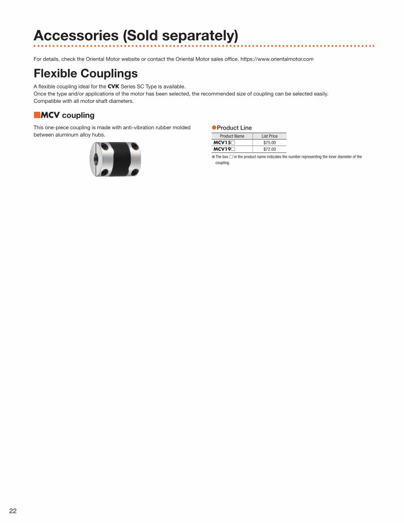
Flexible CouplingsA flexible coupling ideal for the CVK Series SC Type is available. Once the type and/or applications of the motor has been selected, the recommended size of coupling can be selected easily. Compatible with all motor shaft diameters.
■MCV coupling
This one-piece coupling is made with anti-vibration rubber molded between aluminum alloy hubs.
●Product LineProduct Name List Price
MCV15□ $75.00MCV19□ $72.00
●The box □ in the product name indicates the number representing the inner diameter of the coupling.
22
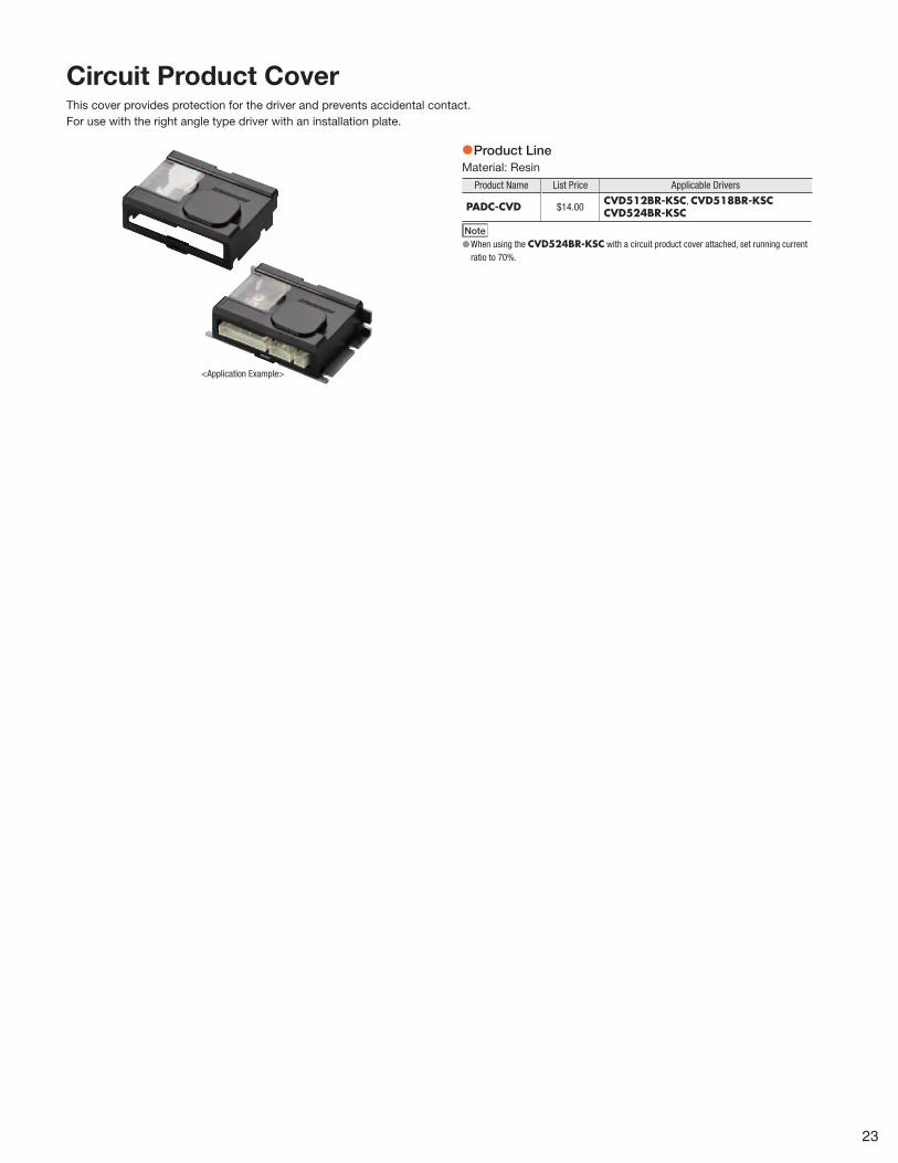
Circuit Product CoverThis cover provides protection for the driver and prevents accidental contact.For use with the right angle type driver with an installation plate.
<Application Example>
●Product LineMaterial: Resin
Product Name List Price Applicable Drivers
PADC-CVD $14.00CVD512BR-KSC, CVD518BR-KSCCVD524BR-KSC
Note ●When using the CVD524BR-KSC with a circuit product cover attached, set running current ratio to 70%.
23

Brushless Motor
BLH Series• This is a slim, high-power brushless motor with a 24 VDC
board-type driver.
• Speed control range is 100 to 3000 r/min.
• Output power is 15 W (1/50 HP) to 100 W (1/8 HP).
Related Products
Copyright ©2018 ORIENTAL MOTOR U.S.A. CORP.
ORIENTAL MOTOR U.S.A. CORP.Western Sales andCustomer Service CenterTel: (310) 715-3301 Fax: (310) 225-2594
Los AngelesTel: (310) 715-3301
San JoseTel: (408) 392-9735
Midwest Sales andCustomer Service CenterTel: (847) 871-5900 Fax: (847) 472-2623
ChicagoTel: (847) 871-5900
DallasTel: (214) 432-3386
TorontoTel: (905) 502-5333
SeattleTel: (425) 214-7559
Eastern Sales andCustomer Service CenterTel: (781) 848-2426 Fax: (781) 848-2617
BostonTel: (781) 848-2426
CharlotteTel: (704) 766-1335
New YorkTel: (973) 359-1100
DetroitTel: (734) 808-0003
PhiladelphiaTel: (610) 605-3103TampaTel: (813) 402-4439
Technical SupportTel: (800) 468-3982 / 8:30 A.M. to 5:00 P.M., P.S.T. (M–F)
7:30 A.M. to 5:00 P.M., C.S.T. (M–F)
E-mail: [email protected]
Obtain Specifications, Online Training and Purchase Products at: www.orientalmotor.com
Printed in USA 17TC #516
Specifications are subject to change without notice. This catalog was published in June, 2018.
This printed material uses ECF (Elemental Chlorine Free) paper and vegetable oil based inks.This combination is environmentally friendly.


