• Turbine Efficiency Losses The thermodynamic performance of a steam power plant
depends on many factors, including cycle arrangement and inlet and exhaust steam conditions. However, the dominant contributor to the overall power plant efficiency is the steam turbine itself. The thermodynamic and aerodynamic performance of the steam turbine is primarily determined by steam path components, including the valves, inlet, nozzles, buckets, steam leakage control devices and the exhaust.
To maximize power plant efficiency, aerodynamic and steam leakage losses in the turbine steam path must be minimized in both the rotational and stationary components. Fig. 1 shows the types of efficiency losses that occur in a typical turbine stage and the approximate percentage that each type contributes to the total stage loss. Nozzle and bucket aerodynamic profile losses, secondary flow losses, and leakage losses account for roughly 80% to 90% of the total stage losses. Nozzle and bucket profile losses can be significant if the blade shapes are not optimized for the local operating conditions. Profile losses are driven by surface finish, total blade surface area, airfoil shape and surface velocity distributions, and proper matching between nozzle and buckets to minimize incidence losses. Equally significant losses can be caused by the complex secondary flows (Fig. 2, adapted from [1] generated as the viscous boundary layers along the inner and outer sidewalls of the steam path are turned through the blade rows. These complex, three dimension flow must be thoroughly understood before effective methods can be developed to reduce the associated losses.
Fig.1: Typical Hp Turbine Stage Efficiency Losses
Steam leakage through the seals between stationary and rotating components of the turbine constitutes an efficiency loss because the leakage flow does not contribute to the work
output of the stage. This loss can be quite significant, particularly at bucket tips. In short high pressure(HP) stages, the tip leakage loss are driven by the high-stage pressure levels and the relatively larger amount of radial clearance area compared to the nozzle flow area. In taller intermediate (IP)and low pressure (LP) stages, the tip leakage loss is driven by the higher reaction levels at the bucket tips, which increases the pressure drop across the bucket tip. Steam leakage through the diaphragm shaft packing and shaft end packing also causes losses, but these are generally of lesser magnitude than tip leakage losses.
Equal attention must be paid to the losses in stationary flow path components, such as inlets, valves, and exhausts. Any pressure drop occurring in these components constitutes a loss inavailable energy and a reduction in work output.
• Key Elements of Aerodynamic Development Programs Development efforts had been underway at GE for many
years to better understand and reduce the various losses listed above. The objective of this long term program was to develop specific design features, for both new turbine sand retrofits of existing units that maximize overall turbine efficiency while maintaining a high degree of reliability and cost effectiveness. Most aspects of this multifaceted development program were being conducted in cooperation with other company components, such as Aircraft Engines, Gas Turbine and Corporate Research and Development (CRD).
The four key elements of GE’s overall aerodynamic development program were:
• Development of better computational fluid dynamics (CFD) computer programs, which allow more accurate predictions of the complex behavior of the steam flow in the turbine.
• Development of new design concepts to improve both baseline and sustained efficiency, making full use of the new CFD codes.
• An extensive laboratory test program to validate the CFD codes and verify the predicted efficiency gains.
• Development of a suite of powerful automation and optimization tools to allow design implementation of advanced aerodynamic design features on a custom basis to maximize efficiency for each specific application in short design cycle times.
This paper reviews recent advances in GE steam path technology resulting from these development initiatives and the impact of these advances on current GE steam turbine designs.
Improvement in Thermal Efficiency of Steam Turbine through Advances in Steam Path
K.R. Mondal
National Seminar on Thermal Power Plant Performance Management - NSTPPPM 115
II. CFD METHODS In order to fully utilize the available energy of the steam
for maximum efficiency, the complex three dimensional flow fields throughout the turbine must be accurately predicted. In particular, a better understanding is needed of the effects of wet steam, viscosity, and unsteady rotor stator interactions if the remaining losses are to be reduced. Recent advances in the development of CFD computer programs have provided GE with the tools needed to achieve better designs with reduced cost and shorter design cycle time.
• Viscous Euler CFD Code In the early 1980s, the GE steam turbine, gas turbine and
aircraft engine businesses began a Long term joint research program with CRD to study secondary flow phenomena using a combined analytical and experimental approach. Analytical investigations included the development of complex computational fluid dynamics computer codes based on three dimensional formulations of the in viscid Euler equations and the viscous Navier-Stokes equations. The initial in viscid code was developed by CRD and called the EULER3D program [2]. A viscous code that included turbulence models was later developed by GE Aircraft Engines and called the Viscous Euler program [3][4].
Comprehensive experimental investigations were conducted to test the validity of the predictions made by the EULER3D code. These tests utilized CRD’s large-scale wind tunnel test facility, and
The results are described in detail in [5]. In this study, EULER3D predictions of the flow in a subsonic turbine nozzle cascade were compared to cascade test data, including lampblack and oil flow visualization studies. Comparisons were made for nozzles with both parallel and diverging sidewalls, and the code was able to predict in viscid flows in turbine blade passages quite well. A unique flow visualization method was developed for the wind tunnel facility to aid in understanding the physics of secondary flows. The flow particle trajectories shown in Fig. 4 were obtained by shining a strobe light on helium filled zero-buoyancy soap bubbles injected into the flow. Fig. 3 clearly shows one leg of the “horseshoe” vortex spiraling around the nose of a nozzle cascade with parallel sidewalls.
In the last few years, the Viscous Euler code has replaced EULER3D as the analysis code of choice for a wide variety of turbo-machinery design problems. Improvements in computer technology have made it practical to run viscous codes such as Viscous Euler on a network of high-powered workstations, without the need for supercomputers.
Fig. 4 shows the Viscous Euler calculation grid on a blade-to-blade plane for a high pressure bucket vane. A similar calculation grid is generated for the nozzle passage, and a complete stage solution is obtained by automatically iterating between the nozzle and bucket solutions as they run in parallel on separate workstations. For a complete 3D solution, up to 250,000 grid points might be needed in each blade passage to accurately resolve secondary flow details. Fig.5 shows Mach number contours for this same vane in subsonic flow, and the trailing.
Fig. 2: Viscous Euler calculation Grid
Fig. 3: HP Bucket
Fig. 4: Secondary flow in Turbine Nozzle Cascade
Fig. 5: Helium Bubble Traces in Nozzle Cascade
Fig. 6: HP bucket-Viscous Euler Mach number
Controls
III. NEW DESIGN FEATURES FOR IMPROVED BASELINE EFFICIENCY
Advanced Vortex Blading- The flow inside a turbine stage must satisfy the requirements of radial equilibrium. The radial equilibrium equations are derived from the equations of motion and basic thermodynamic relations, and express the balance between pressure forces and inertial forces acting on the fluid. Before the advent of powerful computers and modern CFD codes, the complete 3D form of these equations could not be used for practical design purposes. Designers were forced to make simplifying assumptions about the flow
National Seminar on Thermal Power Plant Performance Management - NSTPPPM 116
to reduce the radial equilibrium equations to a manageable form. Dating back to the 1950s, GE steam turbine stages traditionally have been designed using a true free vortex radial flow distribution. In this type of design, the radial components of velocity are neglected and the assumption is made that the product of radius and tangential velocity is constant. These assumptions greatly simplify the radial equilibrium equations and result in a flow characterized by constant axial velocity and constant work at all radii in the blade row. For shorter stages, free vortex designs with tapered and twisted nozzles and buckets can be very efficient, and considerably more efficient than purely cylindrical stages. For longer stages, however, the free vortex design often results in extremely twisted buckets that are difficult to design mechanically, and it produces high tip reactions that lead to high tip leakage losses. GE has for many years designed non-free-vortex stages in LP turbines to achieve better long bucket designs. The CFD codes available today allow accurate solutions of the fully 3D viscous Navier-Stokes flow equations, and designers are no longer bound to the free vortex concept. In 1984, GE initiated a development program to investigate various “controlled vortex” design concepts, in which the radial flow distribution is tailored to maximize the efficiency of individual stages.
This program was accelerated in 1990 and expanded to include the design and testing of a number of “advanced” vortex stage designs that began with the controlled vortex concept and incorporated variable tangential lean into the nozzles. Many of these concepts have been derived from advanced GE aircraft engine design technology, and were developed jointly with GE Aircraft Engines using the Viscous Euler CFD code. An extensive ongoing test program has been underway since 1990 to verify the predicted efficiency gains for these new concepts, utilizing GE’s single-stage subsonic air turbine and the multi-stage low speed research turbine (LSRT) at GE Aircraft Engines. All of these concepts share the following characteristics:
• The radial flow distribution is tailored to maximize efficiency based on the individual stage geometry and operating conditions.
• The total nozzle surface area has been reduced relative to a conventional design by using fewer nozzles per 360 with better aero-dynamic profile shapes that retain the same total mechanical strength as a conventional design.
• In many cases, the number of nozzles in the diaphragm has been reduced by as much as 50%.This provides a net reduction in profile loss with no loss in mechanical integrity.
• Variable tangential or compound lean is used in the nozzles when it produces a significant gain in overall stage efficiency
• Root reaction is increased in varying degrees to improve bucket root performance, and tip reaction is generally decreased relative to a free vortex design to reduce tip leakage
Due to the quite different operating conditions in HP, IP and LP stages, different concepts are used in each type of stage
In the HP section, stage pressure ratios are about 1.2. This pressure ratio is not limited by aerodynamic considerations, but rather by the pressure loading across the diaphragm at the high pressure levels occurring in the HP section. Consequently, nozzle cross-sections must be relatively larger in size than bucket cross-sections to carry the mechanical load. Fig. 11 shows a typical Advanced Vortex HP stage. Fig. 12 compares the radial distribution of reaction and flow angle for this design to a conventional free vortex design. In the Advanced Vortex design, overall stage reaction has been increased somewhat, although more at the root than at the tip, and root reaction is limited to about 10% to minimize thrust on the rotor.
Fig. 6: Advanced Vortex HP Nozzle & Bucket
Fig. 7: HP Stage Nozzle Exit Angle and Reaction Distribution
The flow angle relative to the axial direction has been decreased at the root and increased at the tip to shift flow radially the root. The flow angle shift at the root allows a more efficient, less cambered bucket root section to be designed, as shown in Fig.5. The nozzle and bucket for each stage are carefully designed as a matched set to eliminate bucket incidence angle losses. Due to the relatively low velocities in the stage (see Fig. 6), the small size and strength of the secondary flow vortices, and the short blade height, nozzle lean has not proven to be an effective loss reduction method in this type of stage
In the IP section, stage pressure ratios are generally in the range of 1.2 to 1.3. Velocities are somewhat higher than in HP stages, and blades are longer and more twisted. Fig. 13 shows a typical Advanced Vortex IP stage. Fig. 14 compares the radial distribution of reaction and flow angle for this design to a conventional free vortex design. In these stages, the flow is biased away from the sidewalls toward the more efficient mid-section of the blade by increasing the throat at the pitch line, producing a nozzle that is slightly over cambered at the root and tip relative to the pitch line shape. Compound lean has been introduced in the nozzle to reduce the secondary flow losses, and root reaction has been increased to allow a more efficient, less cambered bucket root section to be designed. As in the HP Stage, the nozzle and bucket for each IP Stage are carefully designed as a matched set to eliminate bucket
National Seminar on Thermal Power Plant Performance Management - NSTPPPM 117
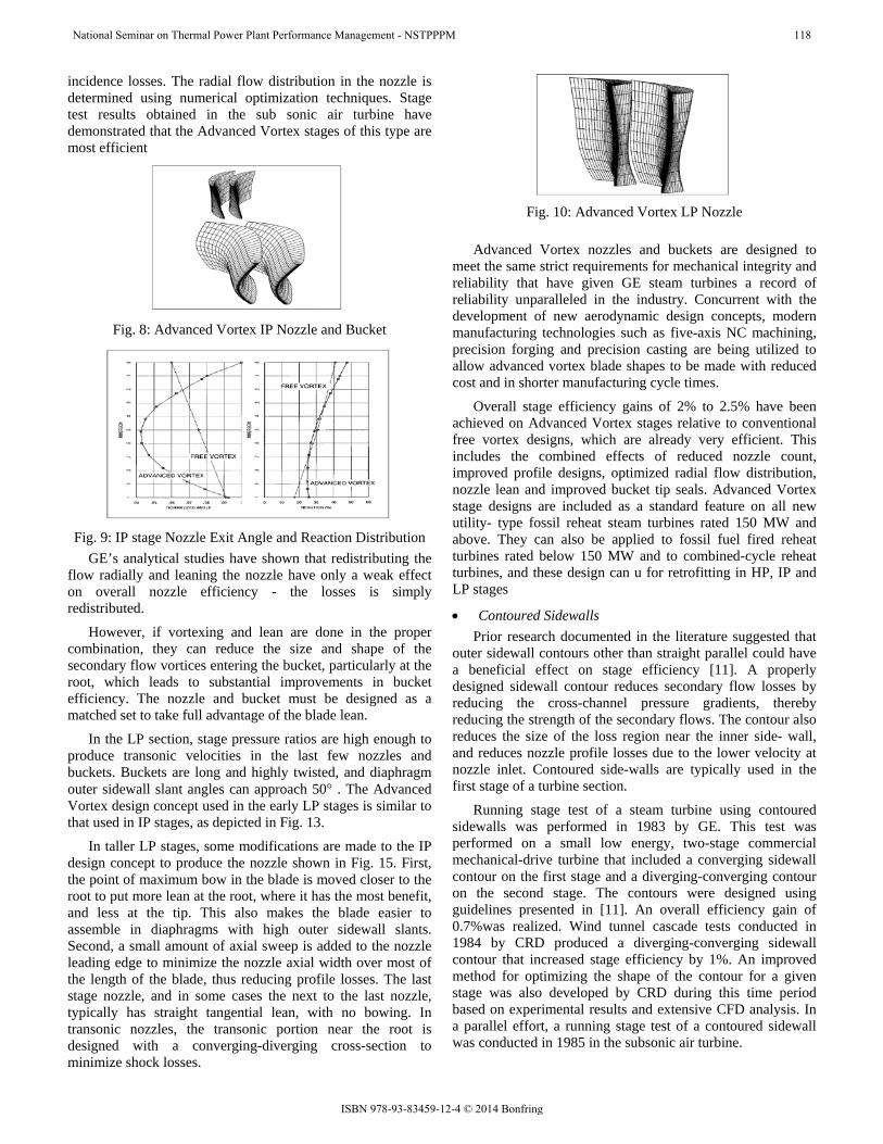
incidence losses. The radial flow distribution in the nozzle is determined using numerical optimization techniques. Stage test results obtained in the sub sonic air turbine have demonstrated that the Advanced Vortex stages of this type are most efficient
Fig. 8: Advanced Vortex IP Nozzle and Bucket
Fig. 9: IP stage Nozzle Exit Angle and Reaction Distribution
GE’s analytical studies have shown that redistributing the flow radially and leaning the nozzle have only a weak effect on overall nozzle efficiency - the losses is simply redistributed.
However, if vortexing and lean are done in the proper combination, they can reduce the size and shape of the secondary flow vortices entering the bucket, particularly at the root, which leads to substantial improvements in bucket efficiency. The nozzle and bucket must be designed as a matched set to take full advantage of the blade lean.
In the LP section, stage pressure ratios are high enough to produce transonic velocities in the last few nozzles and buckets. Buckets are long and highly twisted, and diaphragm outer sidewall slant angles can approach 50 . The Advanced Vortex design concept used in the early LP stages is similar to that used in IP stages, as depicted in Fig. 13.
In taller LP stages, some modifications are made to the IP design concept to produce the nozzle shown in Fig. 15. First, the point of maximum bow in the blade is moved closer to the root to put more lean at the root, where it has the most benefit, and less at the tip. This also makes the blade easier to assemble in diaphragms with high outer sidewall slants. Second, a small amount of axial sweep is added to the nozzle leading edge to minimize the nozzle axial width over most of the length of the blade, thus reducing profile losses. The last stage nozzle, and in some cases the next to the last nozzle, typically has straight tangential lean, with no bowing. In transonic nozzles, the transonic portion near the root is designed with a converging-diverging cross-section to minimize shock losses.
Fig. 10: Advanced Vortex LP Nozzle
Advanced Vortex nozzles and buckets are designed to
meet the same strict requirements for mechanical integrity and reliability that have given GE steam turbines a record of reliability unparalleled in the industry. Concurrent with the development of new aerodynamic design concepts, modern manufacturing technologies such as five-axis NC machining, precision forging and precision casting are being utilized to allow advanced vortex blade shapes to be made with reduced cost and in shorter manufacturing cycle times.
Overall stage efficiency gains of 2% to 2.5% have been achieved on Advanced Vortex stages relative to conventional free vortex designs, which are already very efficient. This includes the combined effects of reduced nozzle count, improved profile designs, optimized radial flow distribution, nozzle lean and improved bucket tip seals. Advanced Vortex stage designs are included as a standard feature on all new utility- type fossil reheat steam turbines rated 150 MW and above. They can also be applied to fossil fuel fired reheat turbines rated below 150 MW and to combined-cycle reheat turbines, and these design can u for retrofitting in HP, IP and LP stages
• Contoured Sidewalls Prior research documented in the literature suggested that
outer sidewall contours other than straight parallel could have a beneficial effect on stage efficiency [11]. A properly designed sidewall contour reduces secondary flow losses by reducing the cross-channel pressure gradients, thereby reducing the strength of the secondary flows. The contour also reduces the size of the loss region near the inner side- wall, and reduces nozzle profile losses due to the lower velocity at nozzle inlet. Contoured side-walls are typically used in the first stage of a turbine section.
Running stage test of a steam turbine using contoured sidewalls was performed in 1983 by GE. This test was performed on a small low energy, two-stage commercial mechanical-drive turbine that included a converging sidewall contour on the first stage and a diverging-converging contour on the second stage. The contours were designed using guidelines presented in [11]. An overall efficiency gain of 0.7%was realized. Wind tunnel cascade tests conducted in 1984 by CRD produced a diverging-converging sidewall contour that increased stage efficiency by 1%. An improved method for optimizing the shape of the contour for a given stage was also developed by CRD during this time period based on experimental results and extensive CFD analysis. In a parallel effort, a running stage test of a contoured sidewall was conducted in 1985 in the subsonic air turbine.
National Seminar on Thermal Power Plant Performance Management - NSTPPPM 118
The stage efficiency with the sidewall contour proved to be 1.5% greater than that for the equivalent stage with cylindrical sidewalls, as shown in Fig. 16. Subsequent tests on improved contoured sidewalls yielded gains of up to 2%. Contoured sidewalls are routinely used in mechanical-drive turbines, ships service turbine-generator sets, and in the HP, IP and LP sections of large fossil fuel fired and nuclear power generation turbines, for both new units and for retrofitting applications.
Fig. 11: Contoured Sidewall Test Data
A typical application might include contoured sidewalls in up to eight stages in the machine, depending on the turbine configuration, for an overall turbine efficiency gain ranging between 0.25% and 0.50% due to the contouring alone.
A family of sidewall contours has also been developed for the new solid particle erosion resistant nozzle designs described in [16]. The contours improve efficiency and, at the same time, increase the resistance of the nozzle to solid particle erosion damage. These contours are available for new and retrofit nozzle box designs for control stage and first reheat stage applications.
• New Last Stage Buckets The last stage bucket is one of the most important
contributors to the performance and reliability of the steam turbine. GE has developed complete families of last stage buckets(Fig. 12) that provide sustained levels of high performance with virtually trouble- and maintenance-free operation. These last stage buckets all share a common continuously-coupled design technology, and they range in size from a 20-inch (508 mm) 3600 RPM bucket to a 48inch (1219 mm) 3000 RPM titanium bucket. Design features of these families include;
• Improved vane profiles, including a convergent-divergent supersonic passage design with high solidity (Fig. 13)
Fig. 12: Continuously Coupled Buckets
Fig. 13: Convergent-Divergent Supersonic Bucket of 3600
RPM Family Tip Profile Design • Improved radial mass flow distribution to optimize
efficiency • Improved tip leakage control that permits moisture
removal (Fig. 24) • Continuously coupled covers, either side entry or
over-and-under (Fig. 19). These covers provide structural coupling and damping, and
also control vane tip flow passage geometry for the reduction of leakage, secondary flow and shock loss.
• Optimum location of mid span connection for structural damping and vibration control, either a loose tie wire or a nub-sleeve connection·
• Self-shielded erosion protection. No separate attachment of shielding is necessary due to the use of high strength erosion-resistant materials with excellent toughness characteristics and a prove
Fig. 14: Continuously Coupled Bucket Tip Design
• With the last stage buckets typically producing 10% of the total unit output, and up to 15% in some combined-cycle applications, improvements in last stage efficiency can significantly impact the output of the total unit.
• Retrofitting older last stage design with a modern diaphragm and last stage bucket can typically improve heat rate and output by up to 1%.
• Typical economic payback periods for the new last stage buckets are two to three years.
[12] & [13] describe the family of modern last stage buckets in more detail.
The modern buckets can be retrofit into most existing units. Table 1 lists the overall heat rate
National Seminar on Thermal Power Plant Performance Management - NSTPPPM 119
• Bucket Tip and Shaft Packing Seals An extended effort, until recently mostly experimental in
nature, has been directed toward finding ways to minimize leakage through bucket tip and shaft packing clearances. Bucket tip leakage controls have typically utilized a single spill strip mounted on the upstream side of the bucket shroud, or two spill strips mounted on either side of the bucket cover tenon. Leakage along the shaft is controlled by packing containing multiple teeth located between the diaphragms and the shaft and at the ends of the shaft. Leakage can be reduced by either reducing the radial clearance between stationary or rotating components, or designing the seal geometry to create a torturous path that induces turbulence and restricts the flow. Experimental data on leakage control has been obtained largely through two-dimensional stationary air tests rather than more expensive 3D rotating steam tests. Stationary air tests allow a much larger variety of leakage control configurations to be tested at relatively low cost. In the past, rotating steam tests were expensive and usually run to determine the overall
effects of design changes, thus making it difficult to separate out the leakage effects. However, GE has developed a unique, cost-effective method for testing new bucket tip seal concepts.
Over the years, GE has tested a great variety of bucket tip seal configurations. Fig. 15 shows sampling of these configurations. The test results show that leakage flow is substantially reduced when a stepped or high-low spill strip is used. The configuration currently used on the majority of HP and IP bucket tip seals includes steps with double teeth on both the upstream and downstream sides of a recessed tenon. The application of these improved radial tip leakage controls improves sustained efficiency as well, because any damage to the improved controls due to a rub results in less increase in leakage than an equivalent rub to a single radial tip spill strip. Slant teeth also help to reduce leakage flow, as long as the proper tooth spacing has been selected. Fig. 17 shows test data obtained in ‘seal test rig’ that illustrates the importance of choosing the optimum ratio of tooth pitch to radial clearance to minimize leakage flow.
Fig. 15: Bucket Tip Leakage Controls and Fig. 16: Side Entry Last Stage Bucket Cover Design Tip Leakage Control
Fig. 17: Slant Teeth Bucket Tip Seal Test Results-Optimum
Tooth Spacing
In recent years, particular attention has been focused on last stage bucket tip leakage control.
In older industrial and mechanical drive turbine designs, the only leakage control provided at the tip of the last stage bucket is the axial clearance between the downstream face of the diaphragm and the leading edge of the bucket band. This clearance generally is larger on the last stage than on any other, and the resultant leakage losses can be significant. If a radial spill band can be placed on the last-stage bucket shroud and a tight radial clearance maintained, stage efficiency can be improved by as much as 3% (depending on bucket length), which is equivalent to about 0.3% in overall turbine efficiency.
National Seminar on Thermal Power Plant Performance Management - NSTPPPM 120
Fig. 16 shows the radial spill band configuration used on the26-inch (660 mm) and 33.5-inch (851 mm) last-stage buckets.
Effect of tip seal leakage flow on downstream blade rows was thoroughly investigated by GE. The flow leaking over the tip of the bucket cover reenters the tip seal passage with high tangential velocity component. While the torturous path through the seal geometry reduces the axial component of the leakage flow, it does relatively little to affect the tangential component. As the leakage re-enters the steam path on the down streamside of the bucket, the still largely tangential flow must mix with the largely axial flow leaving the bucket. This generates mixing losses and can lead to incidence angle problems in the downstream nozzle. Traverse measurements of stage exit swirl angle obtained in the subsonic air turbine and in the low speed research turbine have confirmed this behavior, as shown in Fig. 18. GE has refined the tip leakage models in its quasi -3D flow solver to reflect this behavior (also shown in Fig. 18). This allows designers to more effectively account for this effect in the preliminary design of multi-stage turbines.
Fig. 18: Influence of Tip Seal Re-Entry flow on Stage Exit
Flow Angle-Comparison of Quasi-3D Analysis to Test Data
• Exhaust Hoods The steam leaving the last row of buckets in the turbine is
directed into the condenser inlet by the exhaust casing, also known as the exhaust hood. Poor aerodynamic design of the exhaust hood can produce a large pressure drop from the last-stage bucket exit to the hood exit. This pressure drop constitutes an efficiency loss because it represents energy that cannot be used by the turbine to produce power. A well designed hood can diffuse the flow, causing the static pressure to increase from the last stage bucket exit to the hood exit flange to match the fixed condenser pressure. This pressure recovery gives the turbine an effective back pressure that is lower than the condenser pressure, so that more energy is available for producing power. In this manner, a good diffusing hood can produce a significant overall gain in efficiency. A diffusing hood also decelerates the flow as it approaches the exhaust flange, thus reducing the likelihood of flow-generated noise and vibration in the condenser tubes.
In downward flow configurations (Fig. 19), the exhaust hood must turn the flow downward 90° before it enters the condenser inlet. In the patented GE hood design concept,
structural support plates inside the hood are used to partition the total flow area into smaller passages in which flow diffusion can be carefully controlled. Streamlined steam guides and flow guide vanes are used to further improve the aerodynamic performance of the flow passages so that major flow separations are avoided. Internal flanges, support struts, pipes and other protrusions into the flow passages that cause efficiency losses and generate noise are removed or minimized.
GE’s approach to exhaust hood design in the past was purely experimental. To optimize a new design, the internal flow passages of the hood were duplicated in an exact scale model (Fig. 21) which was tested in an air flow test facility at GE’s Aerodynamic Development Laboratory. Pressure measurements were taken at various points inside the hood model to determine the amount of flow diffusion taking place. Interchangeable parts in the model allowed many different configurations to be tested so that optimum flow passage configurations could be achieved. Since the early 1960s, literally dozens of different exhaust hood models hundreds of different configurations have been tested, and a performance prediction and design method based on various hood geometry parameters has been developed from this extensive test data base.
Axial flow exhausts (Fig. 21) have significant size and efficiency advantages over downward flow exhausts. If the requirements of the overall power plant dictate that the best location for the condenser is on the same level as the turbine exhaust, then an axial exhaust is the preferred choice. Axial flow exhausts are simpler to design and build, and can be much more efficient diffusers than downward flow exhausts because the flow does not have to be turned 90°.
The velocity distribution at the exhaust flange can also be made quite uniform, resulting in improved condenser performance. Single-casing axial exhaust designs can be conveniently base mounted for easier shipment and installation, as shown in Fig. 21.
Axial flow hoods lend themselves to a more analytical design approach because of their simpler geometry compared to downward flow hoods. Numerous papers published in the open literature by a group of researchers at Stanford University (Kline, Johnston, et al.) have been particularly useful. However, the principal reference used as a guideline for the design of axial flow hoods is a paper by Sovran and Klomp[16]. GE has designed many axial flow hoods for commercial applications based on this paper, and laboratory tests on scale models have confirmed the excellent performance of these designs.
GE’s approach to exhaust hood design has improved dramatically in the last few years, with the advent of CFD codes that are capable of accurately modeling the complex geometry and flow phenomena inside exhaust hoods. Fig.22 shows a computer-generated solid model of the internal component of a downward flow diffusing exhaust hood that had been tested in the laboratory using lampblack and oil to visualize the flow.
National Seminar on Thermal Power Plant Performance Management - NSTPPPM 121
Fig. 22: Solid Model of Downward Flow Exhaust Hood for
CFD Analysis
• Positive Pressure Variable Clearance Packing A recent innovation that improves the clearance control at
shaft packing is the GE positive pressure variable clearance packing. Labyrinth seal packing close to the mid span of a high-temperature steam turbine rotor are susceptible to rubbing. Operation below the first critical rotor speed, acceleration through critical speeds, and boiler temperature variations all occur at startup, making the packing most vulnerable during this period. Excess clearance caused by rubbing during the startup of the unit results in increased fuel costs and a reduction in unit capacity. In addition, vibration problems associated with packing rubs can prevent the turbine from getting through its critical speeds, prolonging the startup of the unit. GE positive pressure variable clearance packing provides a large clearance during startup, and reduced clearance after the unit has synchronized. This arrangement minimizes rubs associated with turbine startups while providing optimum sealing when the unit is loaded.
National Seminar on Thermal Power Plant Performance Management - NSTPPPM 122
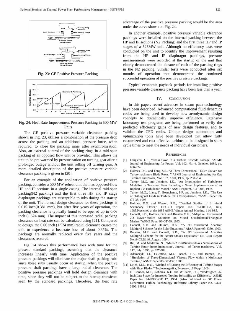
Fig. 24: Heat Rate Improvement Pressure Packing in 500 MW
Units The GE positive pressure variable clearance packing
shown in Fig. 23, utilizes a combination of the pressure drop across the packing and an additional pressure force, when required, to close the packing rings after synchronization. Also, an external control of the packing rings in a mid-span packing of an opposed flow unit be provided. This allows the unit to be pre warmed by pressurization on turning gear after a prolonged outage without the unit rolling off turning gear. A more detailed description of the positive pressure variable clearance packing is given in [20].
For an example of the application of positive pressure packing, consider a 500 MW reheat unit that has opposed-flow HP and IP sections in a single casing. The internal mid-span packing(N2 packing) and the first three HP and IP stage diaphragm packings are susceptible to rubs during the startup of the unit. The normal design clearance for these packings is 0.015 inch(0.381 mm), but after five years of operation, the packing clearance is typically found to be opened up to 0.06 inch (1.524 mm). The impact of this increased radial packing clearance on heat rate can be calculated using [21]. Compared to design, the 0.06 inch (1.524 mm) radial clearance causes the unit to experience a heat-rate loss of about 0.35%. The packings are normally replaced every five years and the clearances restored.
Fig. 24 shows this performance loss with time for the present standard packings, assuming that the clearance increases linearly with time. Application of the positive pressure packings will eliminate the major shaft packing rubs since these rubs usually occur at startup, when the positive pressure shaft packings have a large radial clearance. The positive pressure packings will hold design clearance with time, since they will not be subject to the startup transients seen by the standard packings. Therefore, the heat rate
advantage of the positive pressure packing would be the area under the curve shown on Fig. 24.
In another example, positive pressure variable clearance packings were installed on the internal packing between the HP and IP sections (N2 Packing) and the first three HP and IP stages of a 525MW unit. Although no efficiency tests were conducted on the unit to identify the improvement resulting from the HP and IP diaphragm packings, pressure measurements were recorded at the startup of the unit that clearly demonstrated the closure of each of the packing rings in the N2 packing. Similar tests were conducted after six months of operation that demonstrated the continued successful operation of the positive pressure packings.
Typical economic payback periods for installing positive pressure variable clearance packing have been less than a year.
IV. CONCLUSION In this paper, recent advances in steam path technology
have been described. Advanced computational fluid dynamics codes are being used to develop new aerodynamic design concepts to dramatically improve efficiency. Extensive laboratory test programs are being performed to verify the predicted efficiency gains of new design features, and to validate the CFD codes. Unique design automation and optimization tools have been developed that allow fully customized and cost-effective turbines to be designed in short cycle times to meet the needs of individual customers.
REFERENCES [1] Langston, L.S., “Cross flows in a Turbine Cascade Passage, “ASME
Journal of Engineering for Power, Vol. 102, No. 4, October, 1980, pp. 866-874.
[2] Holmes, D.G. and Tong, S.S., “A Three-Dimensional Euler Solver for Turbo-machinery Blade Rows, ” ASME Journal of Engineering for Gas Turbines and Power, Vol. 107, April, 1985, pp. 258-264.
[3] Turner, M.G. and Jennions, I.K., “An Investigation of Turbulence Modeling in Transonic Fans Including a Novel Implementation of an Implicit k-e Turbulence Model,” ASME Paper 92-GT- 308, 1992.
[4] Turner, M.G., Liang, T., Beauchamp, P.P. and Jennions, I.K., “The Use of Orthogonal Grids in Turbine CFD Computations, ”ASME Paper 93-GT-38, 1993
[5] Holmes, D.G. and Warren, R.E., “Detailed Studies of In viscid Secondary Flows,” GECRD Report No. 85CRD133, July, 1985.Presented at the 1985 ASME Winter Annual Meeting, 11/18/85.
[6] Connell, S.D., Holmes, D.G. and Braaten M.E., “Adaptive Unstructured 2D Navier-Stokes Solutions on Mixed Quadrilateral/Triangular Meshes,”ASME Paper 93-GT-99, 1993.
[7] Connell, S.D. and Holmes, D.G., “A 3DUnstructured Adaptive Multigrid Scheme for the Euler Equations,” AIAA Paper 93-3339, 1993.
[8] Braaten, M.E. and Connell, S.D., “A 3DUnstructured Adaptive Multigrid Scheme for the Navier-Stokes Equations,” GE CRD Report No. 94CRD146, August, 1994.
[9] Rai, M. and Madavan, N., “Multi-AirfoilNavier-Stokes Simulations of Turbine Rotor-Stator Interaction”, Journal of Turbo machinery, Vol. 112, July, 1990, pp.377-384.
[10] Adamczyk, J.J., Celestino, M.L., Beach, T.A. and Barnett, M., “Simulation of Three-Dimensional Viscous Flow within a Multistage Turbine,” ASME Paper 89-GT-152, 1989.
[11] Dejch, M.E., et al., “Method of Raising the Efficiency of Turbine Stages with Short Blades,” Teploenergetika, February, 1960,pp. 18-24.
[12] O ’Connor, M.F., Robbins, K.E. and Williams, J.C., “Redesigned 26-Inch Last Stage for Improved Turbine Reliability an Efficiency,” ASME Paper No. 84-JPGC-GT 17, 1984. (Also published as GE Power Generation Turbine Technology Reference Library Paper No. GER-3399, 1984.)
National Seminar on Thermal Power Plant Performance Management - NSTPPPM 123
[13] O’Connor, M.F., Williams, J.C., Dinh, C.V.Ruggles, S.G. and Kellyhouse, W.W., “An Update on Steam Turbine Redesigns for Improved Efficiency and Availability,” GEPower Generation Turbine Technology Reference Library Paper No. GER-3577, 1988.
[14] Morson, A., “Steam Turbine Long Bucket Developments,” GE Power Generation Turbine Technology Reference LibraryPaper GER-3647, 1990.
[15] Morson, A.M., Williams, J.C., Pedersen, J.R. and Ruggles, S.G., “Continuously Coupled40-InchTitanium Last Stage Bucket Development”, GE Power Generation Turbine Technology Reference Library Paper No. GER-3590, 1988.
[16] Moore, J.H., “High-Power-Density™ Steam Turbine Design Evolution,” GE Power Generation Turbine Technology Reference Library Paper No. GER-3804, 1994.
[17] Sovran, G. and Klomp, E.D.“Experimentally Determined Optimum Geometries for Rectilinear Diffusers with Rectangular, Conical or Annular Cross-Section,” from Fluid Mechanics of Internal Flow, edited by G. Sovran, symposium held at General Motors Research Laboratories in Warren, MI in 1967, published by Elsevier Publishing Co.
[18] Sumner, W.J., Vogan, J.H. and Lindinger, R.J., “Reducing Solid Particle Damage in Large Steam Turbines,” Proceedings of the American Power Conference, Vol. 47, 1985,pp. 196-212. (Also published as GE Power Generation Turbine Technology Reference Library Paper No. GER-3478A, 1985.)
[19] Shalvoy, R.S., et al, “An Improved Coating for the Protection of Steam Turbine Buckets from SPE,” presented at the EPRI Steam Turbine/Generator Workshop, July 20-23, 1993, Albanian.
[20] Morrison, B.L., Booth, J.A. and Schofield, P., “Positive Pressure Variable Clearance Packing,” 1989 EPRI Heat Rate Improvement Conference, Knoxville
[21] Schofield, P., “Maintaining Optimum Steam Turbine-Generator Thermal Performance,” Missouri Valley Electric Association 1981 Engineering Conference, Kansas City, Mo.
[22] Advances in Steam Path Technology by John I. Cofer, John K. Reinker, William J. Summer
ABOUT THE AUTHOR Mr.K.R. Mondal - BE (Mechanical) with honors from NIT, Durgapur; DIIT (Aero-Thermo-Dynamics) with honors from IIT, Chennai. Served Hindustan Aeronautics Limited encompassing design, manufacturing, overhauling & test house for about six years.
Served Durgapur Projects Limited, a Power utility, in different capacities for about 32 years and have
expertise knowledge in all areas of Mechanical Maintenance of (Boiler, Turbine & CHP) large Thermal Power Station. He was member of Regulatory Cell and in-charge of Fuel Supply Management of the Power Plant. Headed Mechanical wing for Renovation and Modernization & Life Extension undertaken by PPIL, the Joint Venture Company of Siemens, Germany and BHEL
National Seminar on Thermal Power Plant Performance Management - NSTPPPM 124