Page 1
Improvement of Safety Characteristics of Stirred Reactors (SR)
VisiMix® Approach to Inherently Safer Design of SR
Y. Nekhamkin, L. Braginsky, Y. Kokotov
VisiMix Ltd.
8 Hamarpe Street
7th Floor, Bynet Bldg.
Jerusalem 97774 Israel
email: [email protected]
Keywords: stirred tanks/reactors, mixing-dependent process, inherently safer design, process safety
technology, process simulation, VisiMix®.
Abstract
Stirred reactors belong to key process equipment used in many branches of the chemical process
industry and characterized by an extremely wide range of process conditions – temperatures, pressure,
heat release or consumption, and, in many cases, significant change of these parameters in the course
of a single operation. Such a wide diversity of process applications results in a notable variety of
design solutions. Lack of satisfactory compliance of the design solutions to the process requirements
creates a risk of accidents.
Since stirred reactors operations comprise ~14% of all accidents in the chemical process industry
caused by different reasons [1], it is evident that a reliable calculation technique (software) permitting
to design a proper reactor for a required chemical process or to evaluate correspondence between the
design characteristics and the process requirements must be considered as an ultimate element of the
inherent safer design/technology (ISD/IST) tool.
The present paper shows that VisiMix® software [2] (being in commercial use since 1996) that
combines simulation tools for various mixing-dependent processes with elements of an expert system
allows predict dangerous situations and find technical means to mitigate/eliminate the probable risks
and hence can become an important part of the ISD/IST concept.
1. Introduction
Stirred reactors whose use is widespread in the CPI allow realize various technological processes
including the following:
homogeneous blending;
liquid-solid mixing (among them suspension, dissolution of solid, liquid-solid extraction,
etc.);
liquid-liquid mixing (among them emulsification, liquid extraction, etc.);
liquid-gas mixing;
homogenization of multi-component mixtures;
single phase chemical reactions in batch, semi-batch and continuous flow reactors;
heterogeneous reactions in liquid-liquid and liquid-solid mixing media;
temperature-dependent chemical reactions in batch, semi-batch and continuous flow reactors);
etc.
Page 2
The present paper stems from the following considerations:
1. A current status of the chemical process industry (CPI) features considerable number of various
accidents occurring during process operation [1, 3…8] caused by different reasons.
2. Stirred reactors belong to the key type of equipment used in all branches of the chemical process
industry. Their operations are followed by ~14% of all accidents in chemical process industry
associated with inadequate process analysis of heat transfer (23%, with main accident contributors:
reduced flow, poor mixing, improper heating sources, power failure, etc.), reaction problems (23%,
with main accident contributors: power failure, excessive heating or deficient cooling, poor mixing,
high charging rate, etc.) and process contamination (16%, with main accident contributors: power
failure, excessive heating or deficient cooling, poor mixing, high charging rate, etc.) [3]. About 71%
of the stirred reactors accidents are related to batch/semi-batch reactors operations [3]. As it was
mentioned in [8], “often the design faults are correlated; e.g. chemical reactivity, stability, and
incompatibility have cause and effect dependencies with process deviations such as temperature,
pressure, contamination or generation of by-products, incorrect reaction data affects the design
decisions on the scale-up of a reactor system, the method of operation selected and the safety limits
used”. Most of the above mentioned accidents contributors result from lack of analysis.
3. Providing process safety technology becomes now one of the basic requirements of the day and it
resulted in the Inherently Safer Design (ISD) concept [9]. According to Dennis C. Hendershot [10]
any process can be “described as inherently safer if it reduces one or more hazards… associated
with the materials and operations used in the process when compared to some alternative process,
and this reduction or elimination is accomplished by characteristics which are permanent and
inseparable parts of the process” and the process engineer challenge is “to identify ways to
eliminate the hazards associated with the process, rather than to develop add-on barriers to protect
people from these hazards” using “appropriate analytical and decision making tools to select him
the best overall process alternative, considering all of the hazards [10].”
Since risk of incident/accident is usually caused by any deviation or consequence of deviations from
normal course of the technological process, adequate process analysis is a fundamental issue of the
reactor safety design.
2. The VisiMix® simulation potential. Main features
Stirred reactors productivity and their quality shall be based on justified calculation that shall be
capable to cover all the unit operations realized in the considered equipment. However both reactor
behavior and the process course in this reactor can’t be adequately accounted by its control and safety
systems under unpredicted changes of the operation conditions which fall beyond the range of the
calculation capabilities. For example, such situations like high degree non-uniformity of disperse
phase, solid phase settling or air insertion/suction from liquid surface are not liable to simulation or
calculations and these phenomena do not show themselves during normal process course but they
become essential with the availability of dangerous situation. As these phenomena can’t be calculated
and thus a necessary condition for inherently safer technology is to define such regimes at the design
stage.
Despite of complexity of processes in the stirred tanks/reactors, there is a tool possessing such
potential – VisiMix® software [2] intended for technical calculations and simulation of mixing-
related process. This software has gained recognition [2, 11] because it provides adequate and
Page 3
complete description of process and equipment configurations based on reliable models verified in
practice.
This paper considers application of VisiMix® software to ISD/IST of various chemical processes in
the stirred reactors. Main features of the VisiMix® software are briefly described further.
The VisiMix® set of software tools intended for technical calculation and simulation of mixing
related processes includes the following programs:
VisiMix Turbulent® for turbulent flow regime (low viscosity flow),
VisiMix Laminar® for laminar flow regime (high viscosity flow and flow of non-Newtonian
liquids),
VisiMix Different Impellers® for simulating mixing devices with different impellers (to be
used with VisiMix Turbulent®),
VisiMix RSDE® for simulation of rotor stator dispersers,
VisiMix Pipe-Line® for hydraulic calculations for low and high viscous and non-
Newtonian liquids in plant pipe lines,
VisiMix Excel® that integrates VisiMix reports in a standard Excel worksheet.
The VisiMix® was developed for process engineers as a universal tool for solving a wide range of
technological problems. Its menu topics (Table 1) enable to analyze main unit operations and to
define their main parameters. The VisiMix® gained recognition because it provides an adequate and a
complete description of process and equipment configuration based on reliable models verified in
practice.
Process / Unit Operation Problem and Key Mixing Parameters
1. Basic Mixing Information Main mixing characteristics
Flow dynamics
Vortex formation
Turbulence, shear rates and stresses
2. Blending (distribution of a solute) Mixing time
Simulation of batch blending
Micromixing
3. Suspension (liquid-solid mixing) Checking “non-settling” conditions
Radial and axial distribution of solid phase
4. Dissolution of solid Complete dissolution
Simulation of a dissolution process
Mass transfer characteristics
5. Leaching (liquid-solid extraction) Collisions of particles
Mass transfer characteristics
Radial and axial distribution of solid phase
Local shear rates and shear stresses
6. Crystallization Uniformity of mother solution
Mixing parameters affecting nucleation and
growth of crystals
Scaling-up parameters
7. Emulsification (liquid-liquid mixing) Characteristics of emulsion
Mixing parameters affecting emulsification
Page 4
8. Liquid extraction Mass transfer characteristics
Mixing parameters affecting liquid extraction
Scaling-up parameters
9. Single phase chemical reaction (batch
reactor
Process simulation
Local concentration of reactants
Non-uniformity of mixing in reactor
Selectivity of reaction
Scaling-up parameters
10. Single phase chemical reaction
(semibatch reactor)
Process simulation
Local concentration of reactants
Non-uniformity of mixing in reactor
Selectivity of reaction
Scaling-up parameters
11. Single phase chemical reaction
(continuous flow reactor)
Dynamic characteristics
Approach to “perfect mixing”
Scaling-up parameters
12. Heterogeneous reaction. Liquid-liquid Mass transfer characteristics
Mixing parameters affecting the reaction
Scaling-up parameters
13. Heterogeneous reaction. Liquid-solid Mass transfer characteristics
Scaling-up parameters
14. Homogenization of multi-component
mixture
Mixing parameters affecting the reaction
Scaling-up parameters
15. Temperature-dependent reaction. Batch,
Semibatch and Continuous flow reactors
A comprehensive set of heat transfer
characteristics
Simulation of thermal regimes
16. Mechanical reliability Stresses in dangerous cross-section
Shaft vibration
17. Thermal safety Analysis of runaway process
Prediction of overheating/overcooling of media
Table 1. VisiMix® Menu (List of Main Unit Operations)
All the VisiMix® codes perform simulation of different technological processes with respect to real
equipment design and process regime parameters. Selection of the equipment types and entering their
parameters is effected by means of the simple user-friendly graphic user interface (GUI). Elements of
the VisiMix® GUI are depicted in the Figure 1. Besides for a user convenience, the VisiMix®
simulation capabilities are sustained by means of the following build-in tools:
databases with properties of applied materials,
HELP system with enhanced technical information that endows it with properties of the
reference source.
The simulation capabilities of the Visimix® software are accompanied with elements of an expert
system. The expert system performs two functions: firstly, it helps an user to enter properties of
applied materials by means of build-in databases, and secondly (the principal), it analyses initial data
and calculation results and issues warning messages whenever the input results in unacceptable
Page 5
process course. Hence, messages offer a mean to define safety range of the basic process parameters.
Typical messages of the VisiMix Turbulent®, and VisiMix Laminar® codes are depicted in the Tab.1
Figure 1. Examples of the VisiMix® GUI Elements
Message Cause of an accident Hazard potential
Mixing power is too high for your
drive
High viscosity or density of
media.
Incorrect drive selection
Possible unexpected stop of
mixing
Shaft breaking (check Shaft
design with VisiMix®)
Complete suspension is
questionable
Big particle size for given
mixing system
Too high concentration of
solid phase
Increase of bending moment and
shaft/sealing breaking
Plugging of outlet from reactor
Hot spot formation
Centrifugal separation of emulsion
is expected
Addition baffles is advisable
Incorrect design for liquid-
liquid mixing reactor
Decrease in dispergation ability
of impeller and interface area
Unpredicted reaction and mass
transfer rate
Vortex reaches impeller!
Gas insertion from surface and shaft
vibration are possible
Too intensive mixing
Not enough baffles
resistance
Impeller too close to surface
Mechanical breaking
Unpredicted way of reaction
Foam formation
Unwanted oxidation
Page 6
After XXX sec have elapsed,
temperature falls outside the
indicated range of process
temperature
Weak heat transfer system
Too low mixing
Not proper design
Unexpected way of the process
Agglomeration of solid particles,
fouling of wall and damage to the
heat transfer.
Increase of pressure
Explosion
This heat transfer agent doesn’t
correspond to process temperature
range
Not proper heat transfer
agent selection
Fail of heat transfer
Rotational frequency of the shaft is
too close to critical frequency.
Vibrations are possible, see SHAFT
VIBRATION
CHARACTERISTICS
Small shaft diameter
Unexpectedly high power
Mechanical breaking
Fluid velocity is too low for
efficient mixing
Not proper design
Unpredicted way of the process
Damage to the product
Plugging of the reactor
Inefficient mixing because of short-
circuiting of flow in impeller area.
See output parameters “Scheme of
main circulation cycles” and
“Circulation flow rate”, and HELP
Formation of stagnant zones is
expected. For recommendations see
HELP, Formation of stagnant zones
Table 2. Examples of messages and their connection with deviations from normal process course
3. VisiMix® application in ISD/IST of chemical processes
Three examples presented below illustrate VisiMix® abilities in tackling safety problems of stirred
reactors: at the design stage (Example 1), under operating conditions (Example 2), and for
incident/accident investigation (Example 3).
3.1. Example 1. This example demonstrates usage of the VisiMix® software at the design stage of the
process based on exothermal catalytic reaction and involving solid catalyst in a stirred reactor.
Calculation of this process shall account possibility of non-uniformity of catalyst distribution inside
the tank and one of the most important requirements to liquid - solid mixing processes - prevention of
sedimentation of solid particles on the tank bottom. Such catalyst non-uniformity will cause localized
overheating that in turn can result in runaway reaction especially for exothermal process. Besides,
catalyst settling at the bottom will retard its emergency discharging in case of incident. The
considered problem from the safety standpoint raises two tasks to be solved.
The first task is to provide Just Suspension Speed (JSS) – the minimum rotational velocity of the
impeller at which there are no stagnant zones at the bottom.
Page 7
The second task is to simulate a second order exothermal reaction in a stirred batch reactor aiming to
avoid runaway reaction that takes place when the energy generated by the reaction is greater than the
energy removed from the reactor.
The process is carried out in in a cylindrical, fully baffled tank with an elliptical bottom equipped
with a downward pumping pitched paddle impeller with 4 blades inclined at 45 (Fig.2).
Figure 2. The diagram of the stirred reactor
Note: A combination of a 4-blade Impeller with 4 radial baffles in one reactor is generally not
recommended, as it may in some cases lead to shaft vibrations. However, as you will see from the
analysis of your present configuration, in this particular case no vibrations were observed.
Properties of the media:
Liquid phase: Organic liquid
Solid phase: Catalyst powder with density of about 2630 kg/m3 .
The particle size range: 150 - 210 microns;
Concentration of the solid phase: 100 kg/m3.
Therefore, there are two tasks to be solved.
The first task is to provide Just Suspension Speed (JSS) – the term that stands for the minimum
rotational velocity of the impeller at which there are no stagnant zones at the bottom. This example
shows how to determine JSS in the case of mixing in a cylindrical fully baffled tank.
The second task is devoted to simulation a second order irreversible reaction carried out in a stirred
batch reactor. VisiMix performs simulation of exothermal reaction based on the analysis of the
equipment and process parameters aiming to avoid runaway reaction that may take place when the
energy generated by the reaction is greater than the energy removed from the reactor.
Problem Solution.
Task 1: Evaluation of Just Suspension Speed (JSS).
Problem of prevention of solid particles sedimentation on the tank bottom reduces to evaluation of
Just Suspension Speed (JSS) – the minimum rotational speed of the impeller that does not result in
settling of solid particles on the tank bottom and ensures the absence of stagnant zones. Although
VisiMix® does not calculate JSS directly, it enables the user to determine this parameter readily.
When calculating any of the parameters in the Liquid-Solid Mixing submenu of the Calculate menu
Page 8
(for instance Axial distribution of solid phase) in cases when settling occurs, VisiMix® issues a
warning message informing the user of possible settling of solid particles. Therefore, to find this
minimum value of rotational velocity, it will suffice to enter any reasonable value of RPM, and then
gradually increase it until the program stops issuing the message that means that this RPM value is
higher than JSS. The first RPM value, which will not result in the warning message, will be the
desired JSS value.
The initial rotation speed taken equal to 60 RPM results in two messages (Fig.3). This means that the
entered RPM value (60 RPM) is lower than JSS. The corresponding graph of axial distribution of
solid phase presented in the Figure 4 shows that at 60 RPM the non-uniformity is about 20%. Gradual
increase of the impeller rotation speed enables to estimate that at 71 RPM the warning message still
appears, while at 72 RPM the warning message will be absent. Choosing a menu parameter
Complete/incomplete suspension manifests in appearance a message (Fig.5). That enables to
conclude that JSS is about 72 RPM.
Figure 3. The messages warning of possible settling of solid phase.
Figure 4. Axial distribution of solid phase (60 RPM).
Page 9
Figure 6. Complete/incomplete suspension information message
Thus VisiMix® by using its simulation abilities along with elements of the expert system enabled to
define minimum rotational speed of the impeller that does not result in settling of solid particles on
the tank bottom and ensures the absence of stagnant zones.
Task 2: Simulation 2nd
order exothermal reaction carried out in a stirred batch reactor.
The exothermal reaction is run according to the stoichiometry
A + B C
The equation for the reaction rate is:
r = k CA CB ,
where r is reaction rate, moles of A, [Lsec], k is reaction rate constant, [L/(molesec)], CA is
concentration of reactant A, [mole/L]; CB is concentration of reactant B, [mole/L].
The reaction rate constant is a function of the system temperature and is given by
k = k0 e -E/RT
where k0 is Arrhenius constant, [L/(molesec)], E is energy of activation, [kJ/mole], R is gas law
constant, [J/(moleK)].
Kinetic reaction parameters were partially borrowed from [12].
The actual process is performed in two stages – initial heating which starts the reaction and
subsequent cooling required for removing excessive heat. The heating is achieved by steam at
atmospheric pressure supplied into the jacket, and the cooling is with ordinary water at 20C
circulated through the jacket with volume flow rate 40m3/h.
The aim of the VisiMix® analysis to define duration of the both process stages – initial heating which
starts the reaction and subsequent cooling required for removing excessive heat. This task is based on
simulation of a second order irreversible reaction carried out in a stirred batch reactor aiming to avoid
runaway reaction that may take place when the energy generated by the reaction is greater than the
energy removed from the reactor.
The maximum allowable temperature of the reactor is equal to the media vapor saturation temperature
(143C).
The first process stage is initial heating. Calculations performed by means of selection Media
temperature as a parameter to be studied in a submenu Heat Transfer. Batch (BH) - Vaporous
agent (VA) at first cause appearance of a warning message informing that at 443 sec (~7.3 minutes) a
Page 10
runaway reaction had started (see Fig.7). A graph with media temperature history is presented in the
Figure 8.
Figure 7. The message warning of the temperature exceeding the prescribed limit
Figure 8. Media temperature. BH. VA.
A parameter Concentration of reactant A. BH. VA shown in the Figure 9 demonstrates course of
the reaction.
Figure 9. Concentration of reactant A. BH. VA.
As seen from Figs 8 and 9, the runaway regime is approached almost at the end of the reaction,
when the reactant concentration is dramatically falling down, in about 7.5 minutes from the start of
Page 11
the process. The obtained information indicates that the second process stage – cooling shall be
started before the process approaches the runaway regime. As switching from steam to cold water is
not instant, duration of the first stage was taken equal to 4.5 minutes from the start of the process. At
this moment the steam supply stops, the cooling water fills the jacket, and the second (cooling) stage
starts. The results of the heating stage will thus serve as the initial data for the cooling stage of the
simulation. Therefore, you should note the values of temperature and reactant concentration in Figures
8 and 9 corresponding to 4.5 minutes from the start of the process. The desired values are 35C and
4.85 mole/liter (for both reactants).
Calculations for the cooling stage shall be performed by means of the Heat Transfer. Batch,
Liquid agent (LA) submenu. Results are presented in the Figure 10 (Media temperature. BH. LA)
and Figure 11. (Concentration of reactant A. BH. LA.). Graphs presented in these figures show that
this scenario, ensuring greater process safety, is at the same time capable of completing the reaction.
The duration of the cooling stage is now about 5.3 minutes, and the total reaction time is about 10
minutes.
Figure 10. Media temperature. BH. VA. The heating stage is 4.5 min.
Figure 11. Concentration of reactant A. BH. LA. The heating stage is 5 min.
These results confirmed the suitability of the selected equipment to the considered exothermal
process, and show the way to define an optimal and safety process regime.
Page 12
Note: if instead of water another cooling agent Dowtherm SR-1 is selected the program will send a
warning message (Fig.12). The reason is that an operating temperature of Dowtherm SR-1 is 121 C
that is less than the process upper temperature limit (143C).
Figure 12. Warning message regarding conformity of the heat transfer agent.
3.2. Example 2. Tackling safety problems of stirred reactors during operations.
Process description. This example taken from [13] considers production of propylene glycol (PG) by
the hydrolysis of propylene oxide (PO).
This exothermal reaction takes place in a 300-gal reactor (Figure 13) at room temperature when
catalyzed by sulfur acid. The process has an important operating constraint. Because of the low
boiling temperature of PO the temperature of the mixture inside the reactor must not exceed 130 F.
Figure 13. The diagram of the stirred reactor (Example 2)
Page 13
Statement of the Problem.
1. Operation of any reactor over prolonged period causes a fouling layer in a tank jacket to grow that
in turn will lead to increase of additional thermal resistance between in-tank media and in-jacket
coolant. The last-mentioned affects the temperature regime inside the tank and may cause runaway
reaction.
2. Rise of the media temperature caused by the fouling growth is usually compensated by increasing,
accordingly, the supply of coolant into the jacket and hence, the coolant flow rate and the
corresponding pressure head on the jacket. The latter is usually used in control systems and
corresponds to the VisiMix® parameter Pressure head on the jacket.
3. Since the capabilities of control systems are limited, it is necessary to ensure the system to maintain
the required pressure head in the considered case. Based on calculation results, the dependence of the
Relative Coolant Pressure Head (on the jacket) on the Fouling Thermal Resistance (“Safety Map” for
this process) was displayed graphically (Figure 14).
Figure 14. Safety Map (Example 2)
The pressure head values used for this graph correspond to the minimum flow rate of the coolant at
which the media temperature does not exceed the allowable limits.
Example 3.3. Tackling safety problems in stirred reactors: incident/accident investigation
Incident Description. An incident took place in the crystallizer for the phosphoric acid production
(with volume >2000 m3) equipped with a massive cast impeller with a tip diameter 5.33 m and mass
about 2000kg and a draft tube. The crystallizer design is similar to the depicted below in the Figure
15. The incident starts shortly after the drive motor startup. It was noticed that the startup was
followed by the shaft vibration. This fact was placed in the center of the accident investigation.
Rel
ativ
e C
oo
lan
t P
ress
ure
Hea
d [
- ]
Fouling Thermal Resistance [ sq.m*K/W ]
Page 14
Figure 15. Crystallizer with a Draft Tube
The equipment menu of the existing VisiMix® version does not consider agitators inserted into a draft
tube. Because of this, VisiMix® application is based on the simplified model that differs from the
original design by the lack of the draft tube (see Figure 16).
Figure 16. VisiMix® Simplified Model
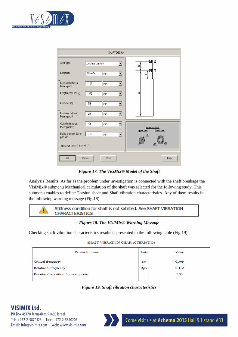
The VisiMix® model of the shaft is presented in the Figure 17.
Page 15
Figure 17. The VisiMix® Model of the Shaft
Analysis Results. As far as the problem under investigation is connected with the shaft breakage the
VisiMix® submenu Mechanical calculation of the shaft was selected for the following study. This
submenu enables to define Torsion shear and Shaft vibration characteristics. Any of them results in
the following warning message (Fig.18).
Figure 18. The VisiMix® Warning Message
Checking shaft vibration characteristics results is presented in the following table (Fig.19).
Figure 19. Shaft vibration characteristics
Page 16
The fact, that the shaft rotational frequency exceeds it critical value, means that after the massive
impeller motor was switched on, the rotation speed increases gradually from the zero value up to the
operation one. This start regime because of the impeller considerable mechanic inertia goes slowly
and there is always a time interval when the shaft rotational frequency is close or equal to critical
frequency that causes resonance oscillation with possible subsequent shaft breakage.
A possible solution of the above problem is to increase the shaft stiffness. It can be achieved by
replacement of the existing shaft with a mechanical scheme (combined console) with a new shaft with
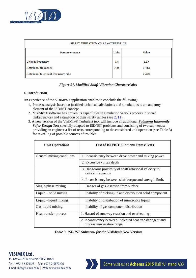
another mechanical scheme (combined beam) presented below in the Fig.20. Modified Shaft vibration
characteristics are presented in the following table (Fig.21).
The table with Modified Shaft vibration characteristics conclusively demonstrates that the rotational
frequency of the modified shaft is much below its critical frequency and thus the modified shaft
design does not jeopardize appearance of the resonance oscillations.
The considered examples demonstrated the VisiMix® efficiency in solving problems associated with
improvement of Inherently Safer characteristics of stirred reactors at the design stage, during
operations and in case of accident investigations.
Figure 20. The VisiMix® Model of the Modified Shaft
Page 17
Figure 21. Modified Shaft Vibration Characteristics
4. Introduction
An experience of the VisiMix® application enables to conclude the following:
1. Process analysis based on justified technical calculations and simulations is a mandatory
element of the ISD/IST concept.
2. VisiMix® software has proven its capabilities in simulation various process in stirred
tanks/reactors and estimation of their safety ranges (see 2, 11).
3. A new version of the VisiMix® Turbulent tool will include an additional Submenu Inherently
Safer Design Test specially adapted to ISD/IST problems and consisting of two submenus:
providing an engineer a list of tests corresponding to the considered unit operation (see Table 3)
for revealing of possible sources of troubles.
Unit Operations List of ISD/IST Submenu Items/Tests
General mixing conditions 1. Inconsistency between drive power and mixing power
2. Excessive vortex depth
3. Dangerous proximity of shaft rotational velocity to
critical frequency
4. Inconsistency between shaft torque and strength limit.
Single-phase mixing Danger of gas insertion from surface
Liquid – solid mixing Inability of picking-up and distribution solid component
Liquid –liquid mixing Inability of distribution of immiscible liquid
Gas-liquid mixing. Inability of gas component distribution
Heat transfer process 1. Hazard of runaway reaction and overheating
2. Inconsistency between selected heat transfer agent and
process temperature range
Table 3. ISD/IST Submenu for the VisiMix® New Version
Page 18
4. Thus VisiMix® allows predict dangerous situations and find technical means to
mitigate/eliminate the probable risks. It means that VisiMix® usage provides stirred reactors
a high degree of Inherently Safer quality.
5. References
1. Ta-Cheng Ho, Yih-Shing Duh, and J.R.Chen, Case Studies of Incidents in Runaway
Reactions and Emergency Relief. Process Safety Progress, Vol.17, No.4 pp.252-262
(1998).
2. Kamarizan Kidam and Markku Hurme, Analysis of equipment failures as contributors to
chemical process accidents. Process Safety and Environmental Protection, 91 (2013), pp.
61-78.
3. C. Kirchsteiger, Trend in accidents, disaster and risk sources in Europe. Journal of Loss
Prevention in the Process Industries, Vol.12, (1999), pp. 7…17.
4. H.- J. Uth, Trend in major industrial accidents in Germany. Journal of Loss Prevention in the
Process Industries, Vol.12, (1999), pp. 69…73.
5. S. J. Kang, Trend in major industrial accidents in Korea. Journal of Loss Prevention in the
Process Industries, Vol.12, (1999), pp. 75…77.
6. S. Wakakura, Trend in chemical hazards in Japan. Journal of Loss Prevention in the
Process Industries, Vol.12, (1999), pp. 75…77.
7. Kamarizan Kidam and Markku Hurme, Origin of equipment design and operation errors.
Journal of Loss Prevention in the Process Industries, Vol.25, (2012), pp. 937…949.
8. T.A. Kletz and P. Amyotte, Process plants. A handbook for inherently safer design. 2nd
Ed.,
Taylor CRC Press, Boca Raton. Fl.(2010).
9. D.C. Hendershot, Inherently Safer chemical process design. Journal of Loss Prevention in
the Process Industries, Vol.10, (1997), pp. 151…157.
10. www.visimix.com
11. CIO Review. Chemical Technology Special, Januar 02 2015, pp.14…15, 38
http://magazine.cioreview.com/December-2014/Chemical/
12. Safety, Health, and Loss Prevention in Chemical Processes. Problems for Undergraduate
Engineering Curricula, (The Center for Chemical Process Safety of the American Institute
of Chemical Engineers) pp. 162 - 164, Problem No. 81.
13. H. Scott Fogler, Elements of Chemical Reaction Engineering, 2nd ed. (Prentice-Hall, Inc.
1992), pp.400 - 405, (Examples 8-4 and 8-5).