Journal of Information Hiding and Multimedia Signal Processing c 2020 ISSN 2073-4212 Ubiquitous International Volume 11, Number 1, March 2020 Improving Data Hiding Capacity in Code Based Steganography using Multiple Embedding Katandawa Alex Kingsley, Ari Moesriami Barmawi Graduate School of Informatics, School of Computing, Telkom University Jalan Telekomunikasi No.1, Bandung 40257, Indonesia [email protected], [email protected]Received July 2019; revised September 2019 Abstract. In this modern era there is rapid increase in use of internet to exchange sensitive information. However, communication via the internet is unsecure and unre- alible. Due to these factors, data hiding techniques has been proposed to increase the confidentiality and security of sensitive information. Moreover, Crandall[14] introduced Code Based Steganography, which merges steganography with coding theory. It imple- mented matrix encoding using linear codes to increase the visual quality of stego image by preserving high embedding capacity. Molaei et al[3] proposed a steganography scheme which implemented Reed Muller codes and modulus function in attempt to increase em- bedding capacity. These fault tolerant schemes have ability to recover secret messages from attacks using error detection and correction. However, existing schemes have low embedding capacity (150%) and low PSNR value (48dB). To overcome this problem, this paper proposed a multiple embedding method that aims to re-embed secrets bits on the same LSBs of the selected pixels based on a secret key. The experiments results shows that the proposed method achieved higher embedding capacity (450%) three times more than Molaei’s method. The proposed method obtained a higher PSNR value of 51dB and higher error correction capability. Keywords: Data hiding, Reed Muller codes, Secret Sharing, Re-embedding, Em- bedding Capacity 1. Introduction. In this modern era the protection of digital data for confidentiality has increasingly emerged as a major concern and top priority. Data hiding is therefore a method of facilitating covert communication in the form of concealing information in a host media called a cover and then being able to extract the message from the cover[6]. The secret data that are applicable include text, images, videos and audio and so as is the cover media. There are two main types of data hiding techniques used for protecting sensitive data from unauthorised access and or tampering these are Watermarking and Steganography[8]. In Watermarking, the hidden or embedded data has a relation with the host or cover media. In Steganography the concealed secret data (e.g text, image etc) and the cover media (e.g text, image, audio, video etc) have no relation, the secret data hidden in stego image is required to be undetectable. Coding Theory is responsible for recovering messages sent via a noisy channel. It extends the message by adding redundant bits which enables error detection and correction[10]. Currently in Steganography, Coding theory serves a major part. Its main objective is to recover hidden messages from the attacked stego images. 14
Abstract. In this modern era there is rapid increase in use of internet to exchangesensitive information. However, communication via the internet is unsecure and unre-alible. Due to these factors, data hiding techniques has been proposed to increase theconfidentiality and security of sensitive information. Moreover, Crandall[14] introducedCode Based Steganography, which merges steganography with coding theory. It imple-mented matrix encoding using linear codes to increase the visual quality of stego imageby preserving high embedding capacity. Molaei et al[3] proposed a steganography schemewhich implemented Reed Muller codes and modulus function in attempt to increase em-bedding capacity. These fault tolerant schemes have ability to recover secret messagesfrom attacks using error detection and correction. However, existing schemes have lowembedding capacity (150%) and low PSNR value (48dB). To overcome this problem, thispaper proposed a multiple embedding method that aims to re-embed secrets bits on thesame LSBs of the selected pixels based on a secret key. The experiments results showsthat the proposed method achieved higher embedding capacity (450%) three times morethan Molaei’s method. The proposed method obtained a higher PSNR value of 51dB andhigher error correction capability.
1. Introduction. In this modern era the protection of digital data for confidentialityhas increasingly emerged as a major concern and top priority. Data hiding is therefore amethod of facilitating covert communication in the form of concealing information in ahost media called a cover and then being able to extract the message from the cover[6].The secret data that are applicable include text, images, videos and audio and so as isthe cover media. There are two main types of data hiding techniques used for protectingsensitive data from unauthorised access and or tampering these are Watermarking andSteganography[8].
In Watermarking, the hidden or embedded data has a relation with the host or covermedia. In Steganography the concealed secret data (e.g text, image etc) and the covermedia (e.g text, image, audio, video etc) have no relation, the secret data hidden instego image is required to be undetectable. Coding Theory is responsible for recoveringmessages sent via a noisy channel. It extends the message by adding redundant bits whichenables error detection and correction[10]. Currently in Steganography, Coding theoryserves a major part. Its main objective is to recover hidden messages from the attackedstego images.
14
Improving Data Hiding Capacity in Code Based Steganography 15
A good steganography scheme consist of three characteristics: high embedding capac-ity, high embedding efficiency and security[19]. The embedding capacity describes thesize of hidden secret message that can be transmitted. Embedding efficiency refers to thevisual quality of the scheme and less image distortions are more secure because it doesnot raise any suspicion to adversaries. Highly secure and robust steganographic schemeshave ability to resist against attacks. Current code based steganography scheme proposedby Molaei[3] have low embedding capacity (150%) and low embedding efficiency of PSNRvalue of 48dB. This is due to the adopted LSB embedding method of higher order signif-icant bits of the cover pixels. The proposed encoder with code rate of 1
2, extended the
secret data by 2. The number of cover pixels to be embedded is increased by 2 also andbecause of that, the image quality reduces significantly. Therefore an introduction of datahiding techniques that improves the embedding capacity and at the same time assuringinvisibility of embedded data are preferable.
This paper proposes a high capacity data hiding mechanism for gray scale images thatmaintains the invisibility of embedded data. It is based on multiple embedding of secretdata into few randomly selected pixels to solve the low embedding capacity problem.The proposed method randomly selects a maximum of 3
4of the cover image pixels for
multiple embedding to guarantee a highly imperceptible stego image. The secret data isencoded using Reed Muller error correction codes before embedding process to increasethe robustness of the scheme.
A cryptographically secure pseudo-random number generator(CSPRNG) called BlumBlum shub [13] was adopted to randomly select cover pixel to be embedded. The seedused to initialize the CSPRNG and the number of embedding cycles was communicatedbetween sender and receiver using a (2,2) secret sharing scheme[16]. This increases thesecurity of the hidden data. The senders’ secret share is encoded with Reed Muller codesbefore embedding into the stego image to increase its resistance against attacks. Further-more, the Modulus function proposed in [5] and LSB embedding were adopted duringembedding process to ensure good visual quality stego images. Experiment results showsthat proposed method benefits the scheme by preventing burst errors which are commonin existing methods. The proposed method provides high PSNR, high embedding capac-ity (450%) and significant error correction capabilities. The error correction capability ofthe proposed scheme increases as the size of the secret image increases.
2. Reed Muller Codes. In this section the Reed Muller error correction codes arediscussed. In Coding theory, error correction codes is a function that expresses numbersin a sequence such that error detection and correction is performed based on the remainingnumbers after introduction of errors[15]. There are two categories of Error correction codesand these are Block and Convolution codes. Block codes encodes a message block of kbits to generate N fixed output data bits, where N ≥ k. In this proposed method, a linearblock code called Reed Muller codes are employed because of their simplicity in encodingmessages and decoding received data.
Definition 2.1. Based on [15], m and r are two positive integers and 0 ≤ r ≤ m. An rth-order Reed-Muller code, RM(r, m) has a message size, k, a code length, N and minimumdistance, dmin, where
k =r∑
i=0
(m
i
)(1)
N = 2m (2)
16 K. A Katandawa, A. M Barmawi
dmin = 2m−r (3)
and the notation is written as: [2m, k, 2m−r]− code
The Reed Muller code can correct a maximum number of errors t given by
t =
⌊2m−r − 1
2
⌋(4)
The choice of m and r values determines the message size of k of the Encoder, the blocksize of N , minimum distance of the code and these have impact on the error correctioncapability of the code.
For example, given m = 4 and r = 1, then k = 5, N = 16, dmin = 8 and t = 3.
2.1. Construction of Reed Muller Codes. There are several ways that can be usedto construct Reed Muller codes. In this study we define Reed Muller codes recursively. Todefine Reed Muller codes inductively, let the 0th order, RM(0, m) defined by two vectors0,1 over Galois field, FN
2 that are repetition codes[4]. For 0 ≤ r ≤ m, the rth orderReed-Muller code R(r,m) is defined recursively by
RM(r,m) = (u, u+ v) : u ∈ RM(r,m− 1), v ∈ RM(r − 1,m− 1) (5)
where u and v represent the code words of the previously constructed codes. Forexample, if r = 1 and m = 2 i.e RM(1,2), the (u, u+ v) construction results in:u ∈ RM(1,1) and v ∈ RM(0,1). Note that RM(1,1) = 00 01 10 11 and u0 = 00, u1 = 01,u2 = 10, u3 = 11. Also note that RM(0,1) = 00 11 and v0 = 00, v1 = 11. Thereforethe resulting code of RM(1,2) is:
RM(1, 2) =
{0000 0100 1000 11000011 0111 1011 1111
}2.2. Encoding Reed Muller Codes. This section describes how a binary message isencoded using Reed Muller Encoder. Firstly, determine the dimensions of the Generatormatrix Gr,m of an rth-order Reed Muller code RM(r, m) with block length of 2m. TheGenerator matrix of RM(r, m) is expressed in [4] as follows:
Gr,m =
[Gr,m−1 Gr,m−1
0 Gr−1,m−1
](6)
where G0,m is a vector of length 2m with all ones and Gm,m is an identity matrix I2m .To encode a message, u ∈ F k
2 , a binary multiplication of the message and the Generatormatrix is performed to form a code word, c ∈ FN
2 using equation (7) in [4]:
c = u ∗Gr,m (7)
For example, assuming a message u = (u0, u1, u2, u3, u4) = (10101) is encoded usingRM(1,4), the Generator Matrix G1,4 is calculated using equation (6)
2.3. Decoding Reed Muller Codes. There are different techniques used for decodingReed-Muller codes, the most common and easily implementable is majority logic decoding.The decoding process converts a code word c to message u. The process consist of 2 stepswhich are majority logic decoding and converting c to u, these steps are described in [17]as follows:
1. Majority decoding: This process is responsible for error correcting of the receivedvector[17]. To perform majority decoding, first consider the code word, c formedfrom encoding an input message, u = (u0, u1, ..., uk−1) represented in [17] as:
c = (c0, c1, ..., cN−1) = u0v0 +∑
1≤i1≤m
ui1vi1 +∑
1≤i1≤i2≤m
ui1ui1vi1vi1
+...+∑
1≤i1≤i2≤...≤ir≤m
ui1,i2,...,irvi1vi1 , ..., vir(8)
if x = (x0, x1, ..., xN−1) is the received vector, then there are r + 1 stages of thedecoding process. For 1 ≤ i1 ≤ i2 ≤ ... ≤ ir−l ≤ m where 0 ≤ l ≤ r, the followingindex set described in [17], is formed as:
S = {ai1−12i1−1 + ai2−12i2−1 + ...air−l−12
ir−l−1 : aij−1 ∈ 0, 1for1 ≤ j ≤ r − l} (9)
S is a set of 2r−l non negative integers that are less than 2m. Assuming E is a set ofintegers 0, 1, ...,m− 1 not in i1 − 1, i2 − 1, ..., ir−l − 1 , such that
where 0 ≤ j1 ≤ j2 ≤ ... ≤ jm−r+l ≤ m−1. Then a set of integers Sc in [17] is formedas
Sc = {dj12j1 + dj22j2 + ...djm−r+l−12
jm−r+l : djt ∈ 0, 1for1 ≤ t ≤ m− r + l} (11)
And then the set of indices, B is formed for each q ∈ Sc such that:
B = q + S = {q + s : s ∈ S} (12)
18 K. A Katandawa, A. M Barmawi
Then the following equation, (14) will determine the decision equations in l-th de-coding stage:
A(l) =∑t∈B
x(l)t (13)
Relation (13) consist of 2m−r+l equations at each stage and follows a binary ad-dition rule. The input message ui1i2...ir−l
is decoded as u∗i1i2...ir−l= 0 if the decision
equations results in zero. And it is decoded as u∗i1i2...ir−l= 1 if the decision equations
results in one. When decoding process has finished l stages, a modified receivedvector is formed as follows:
x(l) = x(l−1) −∑
1≤i1≤...≤ir−l+1≤m
u∗i1,i2,...,ir−l+1vi1vi1 , ..., vir−l+1
(14)
x(l−1) is the modified received vector in the l-th stage of decoding process andx(0) = x. Then proceed to the next stage and repeat the above process until the endof the r + 1 stage to decode all received bits.
2. Converting r′ to u: In this process, the modified received code word is converted tomessage vector. The following equation is used to determine the message vector:
u = r′ ∗GTr,m (15)
The following example illustrate the decoding process. From equation (8) a code wordcan be expressed in terms as (9) in [17]:
Using equation (11) in [10] to decide a set of indices of u and equation (12) to decidea set of indices of c for each corresponding u. Then the check sums for u1, u2, u3 and u4are created using (14):u1 = c1 + c2 = c3 + c4 = c5 + c6 = c7 + c8 = c9 + c10 = c11 + c12 = c13 + c14 = c15 + c16
So if the received code word is: [1 1 1 0 1 1 0 0 1 0 1 1 1 0 1 1], then the checksums for u1, u2, u3 and u4 calculated using equation (15) areu1 : {0, 1, 0, 0, 1, 0, 1, 0}, u2 : {0, 1, 1, 1, 0, 1, 0, 1}, u3 : {0, 0, 1, 0, 0, 0, 0, 0}, u4 : {0, 1, 0, 1, 0, 1, 1, 1}
Considering the majority of each u1, u2, u3 and u4, we conclude that u1 = 0, u2 = 1, u3 = 0and u4 = 1. To determine u0, use equation (15) to calculate the modified received vector:
Using value of x, we decide that u0 = 1. The corrected vector cc is calculated as:
Improving Data Hiding Capacity in Code Based Steganography 19
cc = [0011001111001100]− [1111111111111111] = [1100110000110011]
The equation (15) is used to decode the code word cc, to form the message vector uu:
uu = r ∗GT1,4
= [0000111001101011] ∗
10000...
11001...
11111
= [10101]
3. Molaei’s Method. In this section, Molaei’s method is described. It consist of twophases: Embedding and Extraction Phase. The Embedding phase conceals a secret mes-sage into a cover image to form a stego image while the Extraction phase retrieve the secretmessage from the stego image. Molaei’s method implements coding theory concepts, mod-ulus function and steganography to improve embedding capacity and robustness againstdifferent kinds of noise attacks[3]. However, this method has low embedding efficiency(PSNR) and embedding capacity because it embeds secret data into the first and secondLSBs of all pixels of the cover. It implements the LSB embedding using modulus functiondescribed in section (3.1).
3.1. Modulus Function. A steganographic technique to increase the visual quality ofthe stego image using modulus functions was proposed by Thien and Lin [5]. A modulusfunction is defined as c = a mod b, where a is the dividend, b is the divisor, and c isthe remainder. For example, 5 mod 4 equals 1, that is, the division of 5 by 4 leaves aremainder of 1. Let x be a pixel used to hide data in the cover, z be the decimal value ofthe block/unit bits in the range 0 to 2n− 1. The embedding process of modulus functionis employed to hide zi unit in the ith pixel of cover xi. The difference ddi between the twovalues is computed using the following equation in [5]:
ddi = zi − (xi mod 2n). (16)
where n is the index of the low order bit of each pixel to be embedded. From ddi theminimum variance is determined using the following equations in [5]:
ddi′ =
ddi if −
⌊2n−12
⌋≤ ddi ≤
⌈2n−12
⌉ddi + 2n if −2n + 1 ≤ ddi ≤ −
⌊2n−12
⌋ddi − 2n if
⌈2n−12
⌉≤ ddi ≤ 2n
(17)
However, the value of dd′i can exceed the range 0 to 255, so equation (18) in [5] is useddetermine the final pixel value xi after embedding as follows:
x′i =
xi + ddi
′ if 0 ≤ xi + ddi′ ≤ 255
xi + ddi′ + 2n if xi + ddi
′ ≤ 0
xi + ddi′ − 2n if xi + ddi
′ ≥ 255
(18)
20 K. A Katandawa, A. M Barmawi
The extraction of the embedded data from the n order bits is done using the followingequation in [5]:
zi = x′i mod 2n (19)
3.2. Overview of Embedding phase. The embedding phase is responsible for hidingsecret data into cover media. It hides a secret binary data SD in a gray-scale cover imageC of height H and width W and generates a stego image C ′. The block diagram of theembedding process is shown in Fig 1.
Figure 1. Embedding process of Molaei’s Method
The embedding process is done using the following process:
1. Dividing the pixels of I: The secret data is divided into blocks that will enableeasy encoding of the secret data. The first B bits are divided into nb0 blocks b =(b0, b1, ..., bk0−1) of equal sizes equal to k0, where 1 ≤ B ≤ H x W
2, k0 is the message
block size of the RM(1,3) code computed using equation (1). The number of blocksnb0 to be embedded into first LSBs is calculated using equation (20):
nb0 =
⌈B
k0
⌉(20)
Considering SD > B, the remaining (SD − B) bits are also divided into nb1blocks bb = (bb0, bb1, ..., bbk1−1) of sizes k1, where 1 ≤ (SD − B) ≤ H x W
4, and k1
is the message block size of RM(2,5) computed using equation (1). The number ofblocks nb1 is calculated using equation (21):
nb1 =
⌈(SD −B)
k1
⌉(21)
2. Encoding the secret blocks: The blocks b and/or bb are encoded to enable errordetection and correction to be performed from attacked stego images. Considerall nb0 blocks, encode each block b using RM(1,3) code to form code word c =(c0, c1, ..., cN0−1) of size N0, where N0 is block size of RM(1,3) code calculated usingequation (2). Consider all nb1 blocks, encode each block bb using RM(2,5) codesto form code word cc = (cc0, cc1, ..., ccN1−1) of size N1, where N1 is block size ofRM(2,5) code calculated using equation (2).
3. LSB embedding using Modulus Function: In this process the encoded secretblocks are hidden or embedded into the pixels of the cover image. The two sequenceof code words c and cc are embedded into the first and second LSB of each coverpixel respectively. For each block of nb0 blocks, consider the decimal value of eachci to be embedded into each pi and calculate the difference value ddi using equation(16) where n = 1. Determine dd′i using equation (17). The modified pixel value ppiis calculated by equation (18).
4. Repeating procedure 3 to embed the nb1 blocks of cc into sequence of modified pixelblocks pp where n = 2. The output of the embedding process are modified pixelvalues pp′ which forms the stego image C ′.
Improving Data Hiding Capacity in Code Based Steganography 21
The equations (16), (17) and (18) were implemented to reduce the difference be-tween the original pixel values and modified pixel values. This increases the visualquality of the stego. The embedding process only hides secret data in both first andsecond LSBs of the cover.
3.2.1. Determining the Embedding Capacity of Molaei’s Method. The max-imum size of secret data Dmax that can be embedded is calculated using equation(22) in [3]:
Dmax =n∑
i=0
⌊H ∗W
2mi
⌋∗ ki (22)
where k is the message block size of RM(r, m) encoder and n is the number ofLSBs used for embedding. The embedding capacity EC is then determined usingequation (23):
P =Dmax
H ∗W(23)
3.3. Overview of Extraction phase. In this section the extraction process is discussed.The extraction phase aims to retrieve the hidden data successfully. The secret data SD isretrieved from the Stego image C ′. The block diagram of the extraction process is shownin Fig 2.
Figure 2. Extraction process of Molaei’s Method
1. Modulus Function: The process aims to extract the secret encoded bits first.Equation (19) is used to extract the decimal values zii of the secret data, for 1 ≤ii ≤ H x W and n = 1. Each decimal value in zii is converted to binary to form asequence of extracted bits Ez.
2. Dividing extracted data into blocks: The extracted bits Ez is divided intoblocks of size equal to block size of the RM(r, m) Decoder. The first Fb bits of Ezare divided into nc0 blocks c = (c0, c1, ..., cN0−1) of equal sizes equal to N0, where1 ≤ Fb ≤ H x W , N0 is the block size of the RM(1,3) code. The number of blocksnc0 is calculated as follows:
nc0 =
⌈B
N0
⌉(24)
3. Decoding the extracted blocks: The blocks are decoded to recover the secretdata. For all the nc0 blocks, each code word block c is decoded using RM(1,3)decoder to form a secret block b = (b0, b1, ..., bk0−1).
4. Increase n to extract data in second LSB and repeat step (1) to (3) using 1 ≤ ii ≤H x W
2, number of blocks nc1 =
⌈H x W2∗N1
⌉, where N1 is the block size of the RM(2,5)
code. Decode using RM(2,5) decoder as described in section (2.3).5. Output: The output of the process is a sequence of bits from the Decoder which
represent the secret data.
22 K. A Katandawa, A. M Barmawi
4. The Proposed Method. This section discusses about a steganographic techniquethat offers high embedding capacity, high error correction capabilities and high visualquality. The proposed method is discussed in detail. It consist of two main processes,embedding process and extraction process. The proposed method introduced a PRNGcalled Blum Blum Shub to generate random sequence of integers that represent pixelpositions of the Cover image. The secret message was embedded and extracted into andfrom pixels on these positions orderly. The seed of the PRNG was communicated using(2,2) Visual Cryptography scheme. The concepts of Blum Blum Shub and (2,2) VisualCryptography scheme are discussed in [13] and [16] respectively.
4.1. Overview of Embedding Process. In this section, the embedding process is de-scribed. The process is responsible for embedding secret data securely. There are threeinput images to this process, the cover image CI, agreed image A and secret image SI.The Sender and Receiver agree on an image A before the embedding and extraction pro-cesses begins. Fig 3 shows how a secret message is embedded into a cover using an agreedimage to generate Agreed and Stego image.
Figure 3. Embedding Process of Proposed Method
The secret image pixels are first decomposed into bits and are encoded with Reed Mullererror correction codes. First order Reed Muller RM (1, 4) codes have been introducedbecause of their high Error Correction Capacity, efficiency and relatively easy to decode.To increase the security of the secret data, a pseudorandom number generator (PRNG)was introduced to randomly generate pixels to be embedded from the cover. If the seedof the PRNG is not known then the hidden secret data cannot be extracted correctly.
The scheme implements LSB embedding using modulus function to embed the encodedsecret data into 3
4of the cover image pixels. Only 3
4of the cover image pixels were used
to increase the visual quality of the final Stego image. In other words, if the sizeof the cover image is H * W , where H is the height and W is the width ofthe cover image then the number of pixels used to embed the secret imageis 3
4∗H ∗W . If the size of the encoded secret data exceeds 3
4of the cover image pixels,
the data is re-embedded into the same randomly generated pixels using a key. The keycontains Seed and number of cycles. The Key is securely distributed to the receiver using(2,2) VCS mentioned in [16]. This further increases the security of the embedded secretdata.
The following definition discusses how the embedding capacity is determined using theproposed method.
Improving Data Hiding Capacity in Code Based Steganography 23
Definition 4.1. Given p pixels of a Cover image CI of height H and width W wherep ≤ 3
4∗ H ∗W . If n secret bits are re-embedded into each LSB of the p pixels, then the
total secret bits ST that can be embedded into the cover image CI is:
ST = p . (n+ 1) (25)
and the Embedding Capacity EC expressed as a percentage is determined by
EC =ST
H ∗W=p . (n+ 1)
H ∗W(26)
For example, consider a Cover image of size H = 512 and W = 512. Assuming n =5 secret bits are re-embedded on the LSBs of p = 3
4* H * W = 3
4* 512 * 512 = 196608
pixels. The total secret bits ST that can be embedded into the cover image is calculatedas:
ST = 196608 . (5 + 1) = 1179648 bits (27)
and the Embedding Capacity EC is calculated by
EC =1179648
512 ∗ 512= 450% (28)
The following sections describes each sub process of the embedding process in detail asfollows:
4.1.1. Encoding Process. In this process the encoding process is discussed. Reed Mullerencoder discussed in section(2.3) is responsible for encoding secret data before embeddingsuch that the secret data is recoverable using error correction if the stego image encountersattacks. The encoding process consist of the following sub processes as shown on Fig 4.
Figure 4. Encoding Process
The secret image SI with height H0 and width W0 is decomposed into bits and encodedby RM(1,4) Encoder to generate sequence of code words C using the following three sub-processes:
1. Decomposing pixels into Constituent Bits : The pixel values of the secret image areconverted into bits because of the binary Reed Muller codes that has been introduced.Each pixel of SI (si, 1 ≤ i ≤ H0 * W0) is converted to a byte. Each byte isbroken down into bits and the output of the process is a sequence of all bits sb =(sb0, sb1, ...., sbY ) where Y = 8 * H0 * W0.
2. Dividing bits into blocks : The process divides secret bits into equal sized blocks asrequired by the Encoder such that the encoding process is more efficient. The inputto the process is a sequence of secret bits sb and message length k2 of the RM(r1,m1)encoder.
Definition 4.2. Let Y - k2, and the secret bits sb being divided into n blocks mb(q) =
(mb(q)0 ,mb
(q)1 , ...,mb
(q)k2−1) of length k2 where n =
⌈Yk2
⌉and (1 ≤ q ≤ n).
The number of zero bits Zn to be added to the nth block are:
Zn = Y mod k2 (29)
24 K. A Katandawa, A. M Barmawi
For example, consider secret bits sb = [1010111100110] are to be encoded byRM(1,4) encoder. Using equation (1), the message length k2 = 5. The secret bitssize Y = 13. Therefore 13 - 5. The number of blocks n is calculated as follows:
n =
⌈Y
k2
⌉=
⌈13
5
⌉= 3
The number of zero bits Zn added to 3th block are determined by:
Zn = (3 ∗ 5)− 13 = 15− 13 = 2. (30)
Therefore the blocks to be encoded are : mb(1) = [10101], mb(2) = [11100] andmb(3) = [11000]
3. RM (r1,m1) Encoding : The Encoder is responsible for converting the secret messagebits into code words which will enable error detection and error correction. Theinput to the process at each instance is a block mb(q). For all n blocks, encode eachmb(q) using RM(r1,m1) error correction code using equation (7) to form codewords
cw(q) = (cw(q)1 , cw
(q)2 , ..., cw
(q)N2
) where N2 = 2m2 . Decompose the code words cw(q) intoconstituent bits, for (1 ≤ q ≤ n). Therefore the output of the Encoder is a sequenceof bits, eb = eb0, eb1, ..., ebET
formed from decomposing all code words, where thetotal encoded bits size ET after encoding process is: ET = 8∗H0∗W0∗N2
k2
4.1.2. Generating Key Trace. This segment discusses about how the Key Trace is gener-ated. Key Trace are the sequence of bits generated from XORing the encoded bits andthe chosen Reference Key bit value. The main purpose of this process is to increase theoverall hiding capacity of the scheme by re-embedding secret bits on the pixels of thecover image. Fig 5 shows how the Key Trace bits are generated.
Figure 5. Key Trace Generation
This process is executed if and only if the size of the encoded bits ET is greater than34
* H1 * W1, where H1 and W1 are the height and width of the cover image I. The keytrace KT is generated from the encoded bits eb using the following 4 steps:
Step 1 . Inputting sequence of encoded bits eb and Reference Key. A reference key R isany binary value of choice ie R ∈ 1, 0.Step 2 . Determining how many bits are to be embedded into each pixel of the cover, callednumber of cycles Nc defined as follows:
Theorem 4.1. Given the total number of encoded bits ET embedded on maximum capacityof single LSB which is equal to 3
4∗H1 ∗W1 (based on definition on page 12). The number
Improving Data Hiding Capacity in Code Based Steganography 25
of cycles Nc is:
Nc =ET
34∗H1 ∗W1
(31)
Proof. The number of cycles is a function of the total number of encoded bits ET . Sincethe total number of encoded bits ET can be greater than the maximum capacity of singleLSB (3
4∗ H1 ∗W1). This results in more than 1 bit to be re-embedded into each pixel.
Therefore, in the case ET ≥ (34∗ H1 ∗W1), the number of cycles re-embedded into each
pixel Nc is a equal to the number of encoded bits ET divides by the maximum capacityof single LSB which is equal to 3
4∗H1 ∗W1. Thus it is proven that:
Nc =ET
34∗H1 ∗W1
Step 3 . Dividing the encoded bits eb into block with the length of dNce and the remainderis divided into length of bNcc. The following theorem defines the number of pixels thatcan be re-embedded with dNce bits h and he number of pixels that can be re-embeddedwith bNcc bits h′.
Theorem 4.2. Suppose the number of secret bits eb and the number of cycles Nc is aninteger which cannot divide eb, in other words Nc - eb. Thus there are pixels which arere-embedded with length dNce bits and others with bNcc bits. So the number of pixels thatcan be re-embedded with dNce bits is:
h =3 ∗H1 ∗W1 ∗ (Nc − bNcc)
4(32)
and the number of pixels that can be re-embedded with bNcc bits is:
h′ =3 ∗H1 ∗W1
4− h (33)
Proof. From Theorem 4.1, each pixel from the (34∗ H1 ∗ W1) of the cover pixels is re-
embedded with Nc cycles then it means that the number of bits that can be embedded is(Nc∗ 3
4∗H1∗W1). Since Nc may not be an integer i.e Nc /∈ Z, there is a set of pixels that is
re-embedded dNce times and another bNcc times. In case of db where the size is dNce thenthe number of pixels re-embedded with dNce secret bits is equal to the difference betweenNc and the float of Nc multiplied by the maximum capacity of single LSB (3
4∗H1 ∗W1).
In other words, the number of pixels that can be re-embedded with dNce bits is equal to:
h =3 ∗H1 ∗W1 ∗ (Nc − bNcc)
4
The number of pixels that can be re-embedded with bNcc bits is the difference betweenmaximum capacity of single LSB and he number of pixels that can be re-embedded withdNce bits h which is:
h′ =3 ∗H1 ∗W1
4− h
26 K. A Katandawa, A. M Barmawi
Step 4 . Considering each of the blocks db and db′ , the Key Trace block CK and Coverembeddable bit E are determined using algorithm 1:
Algorithm 1: Generation of Key Trace block and Cover Embeddable Bit
Input: Blocks db or db′, Number of cycles Nc, Reference Key ROutput: KeyTrace block CK and Cover Embeddable bit E
1 t← NC
2 CKt−1 ← dbt ⊕R3 while t > 0 do4 if t == 1 then5 E ← CKt ⊕ dbt6 Append E to Em
7 else8 CKt−1 ← dbt ⊕ CKt
9 t← t− 1
For each block of size n, the process creates a key Trace block of size n - 1. The outputare two sequences of bits,a). Key Trace, KT which is a decomposition of all blocks CKi into constituent bits.
Definition 4.3. Let Nc be the number of cycles per pixel as defined in Theorem (4.1).From Theorem 4.2, the total number of bits to be re-embedded on all pixels called KeyTrace KT is:
|KT | = (h. dNce) + (h′.Nc) (34)
b). And Em bits that are embedded into the cover image.
4.1.3. Generating random pixel positions. This segment discusses how the random pixelpositions are generated. The process uses, Blum Blum Shub, a cryptography pseudorandom number generator, PRNG described in [13] to generate random sequence of bits.The bits are grouped into 18-bit block and converted to integers between 1 and H1 *W1. The generated integers represent pixel positions on the cover image that are used forembedding secret bits Em.
The secret bits are embedded according to the order of the sequence generated. If theseed of the PRNG is not known then the embedded pixel positions are not known andthe secret message cannot be extracted correctly. This process was introduced to increasethe security of the embedded secret message. To generate a sequence of random pixelpositions, pp = pp1, pp2, ..., ppL, the function inputsa). Seedb). Length L of pp where,
L =
ET if 1 ≤ ET ≤ (3
4∗H1 ∗W1)
| Em | if ET ≥ (34∗H1 ∗W1)
(35)
The output is a random sequence of integers values pp = (pp1, pp2, ..., ppL) where 1 ≤ppi ≤ H1 ∗W1 . For example: 120132 145 9987 97 103110 125 14285 92 117 197 203210.
4.1.4. Embedding secret bits into Cover Image. This segment discusses how the secret bitsare embedded into the cover image. It is responsible for efficiently hiding the encoded
Improving Data Hiding Capacity in Code Based Steganography 27
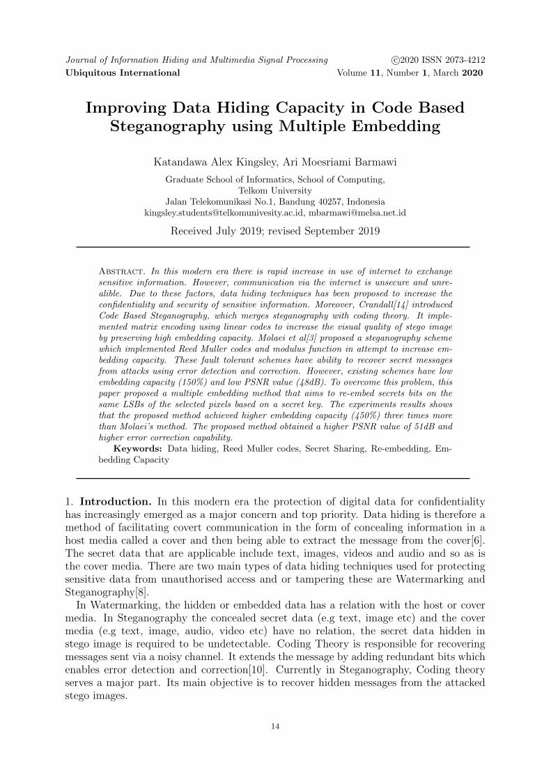
secret bits on randomly generated Cover Image pixels.The process require two inputs :a). The sequence of embedding bits EB, where:
EB =
eb if 1 ≤ ET ≤ (3
4∗H1 ∗W1)
Em if ET ≥ (34∗H1 ∗W1)
(36)
b). Sequence of randomly generated integers ppLSB embedding using modulus function described in section (3.1) was used to embed
all bits of EB on Cover pixels of index pp. It is implemented because of its simplicity inembedding and extraction. The embedding process is done as follows:
Step 1: Considering the decimal value of each bit in EB to be embedded on each pixelpxi on index ppi.Step 2: For each EBi and pxi with n = 1, calculating the difference value ddi usingequation (16). Determine dd′i using equation (17). And lastly, the modified pixel valuepp′i is calculated by equation (18).Step 3: Performing the same procedure for 1 ≤ i ≤ L. The output of the embeddingprocess are modified pixel values pp′ which forms the stego image I ′.
4.1.5. Embedding Key Trace into Agreed Image. In this segment, a sequence of Key Tracebits KT are embedded into the image A of height H2 and width W2. The image Ais a grayscale image that has been agreed upon between Sender and Receiver beforecommunication of the secret message. To embed KT the following process was performed:
1. Determining the number of LSBs nn to be embedded: The value of nn is calculatedas follows:
nn =| KT |H2 x W2
(37)
If nn is a not an integer, then there are two sets of block sizes,(a) The first (dnne ∗H2 ∗W2) bits are divided into blocks w of size dnne, such that
w = (w1, w2, ..., wdnne) and(b) The remaining |KT | − (dne ∗ H2 ∗W2) bits are divided into blocks w of size n,
such that w = (w1, w2, ..., wn) where n ≥ 1.But if nn is an integer, then all KT bits are divided into blocks w of size nn, such
that wi = (w1, w2, ..., wnn).
2. Performing LSB embedding using Modulus function: To embed the Key trace bitsinto the agreed image, the modulus function was applied to increase the visual qual-ity of the resulting stego. The method reduces the difference between the originaland final pixel values using equations (16) and (17). To embed the all blocks w, thefollowing process was performed:
(a) Considering the decimal value z of each block in w to be embedded into eachpixel pa of image A. For the first ((nn−bnnc)∗H2 ∗W2) decimal values we haven = dnne, calculate the difference value ddi using equation (16). Determine dd′iusing equation (17).The modified pixel value pa′i is calculated by equation (18).
(b) Performing the same procedure for the last ((H2 ∗W2)− (nn−bnnc) ∗H2 ∗W2)decimal values where n = bnnc. The output of the embedding process aremodified pixel values pa′ which forms the stego image A′.
28 K. A Katandawa, A. M Barmawi
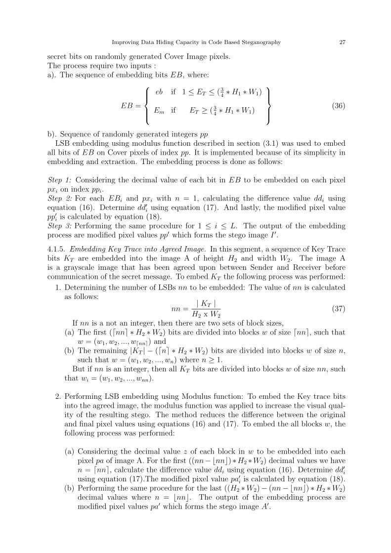
4.1.6. Generating Shares from Secret Key. In this segment, the process is designed tosecurely communicate the seed, number of cycles Nc and height H0 and width W0 of thesecret image. Fig 6 shows how the Key Trace bits are generated.
Figure 6. Share Generation
A Key in form of binary image is generated based on these 4 parameters. (2,2) visualcryptography was later implemented on the Key to generate shares because of its lowcomplexity nature in encoding and decoding. The following generation of key and sharesis described as follows:
1. Generating Key: The function of this component is to create a secret key duringthe embedding process to enable easy and successful extraction of the hidden secretimage, SI. The process require 3 input texts:(a) Seed, SE: An integer that initialize the PRNG.(b) Number of Cycles Nc: It is the result after dividing the Total encoded secret bits
by 34
of the cover image.(c) Height H0 and Width W0 of the secret image
The output of the process is a binary image consisting of SE, Nc, H0 and W0.The three input text are converted from text to binary image using the followingprocess:(a) Concatenating SE, Nc, H0 and W0 separating each with a space character to
form, Txt. Such that, Txt = SE + Nc + H0 + W0.(b) Representing each character in Txt by (0, 1)-matrix, Tg of dimensions m′ x n′
with 0s and 1s arranged to show the character Txtg visually, where 1 ≤ g ≤ |Txt|, m′ = 16 and n′ = 14.
(c) Combining all Ti to form one binary matrix T ′ of size m′′ x n′′, where m′′ =m′ ∗ |Txt| and n′′ = n′ ∗ |Txt|
The binary matrix T ′ is referred to as the Secret Key.
2. Generating Share: (2, 2) visual cryptography is implemented on T ′ as discussed in[16] to increase the security of the secret key while requiring less computation time.The input to the process is a binary matrix, T ′ of size mm x nn. The process performencryption of T’ as described in [16] to generate 2 random binary matrices, T ′1 andT ′2 of sizes mm x 2nn, referred to as Share 1 S1 and Share 2S2 respectively. S1 isdistributed securely to the receiver while S2 is embedded into the stego image.
For example, assuming the seed SE = 262139, Number of cycles Nc = 0.01,Height of secret image H0 = 10 and Width of secret image W0 = 6. The stringTxt = 262139 0.01 10 6, and the binary image T ′ is shown in Fig 7. (2,2) Visualcryptography creates two shares S1 and S2 shown in Fig 8.
Improving Data Hiding Capacity in Code Based Steganography 29
Figure 7. Example of Key Generation
(a) Share 1 (b) Share 2
Figure 8. The generated Shares
4.1.7. Embedding Share 2 into Stego Image. In this segment, the embedding of Share 2S2 is described. Firstly, S2 is encoded with RM(r1,m1) code to enable error correctionof error bits. The encoded S2 is embedded into Stego I ′ such that the correct receiver,possessing S1, can extract S2, decode and be able to stack both shares to retrieve SE,Nc, H0 and W0. The embedding of S2 to generate a new stego image is done by thefollowing process:
1. Inputting the Stego image I’, T ′2 and message length k2 of RM(r1,m1) encoder.2. Dividing S2 into linear blocks of size k2: The binary matrix, T ′2 is decomposed to
single linear block of bits, T ′′2 = t′′1, t′′2, ...., t
′′n′′∗2m′′ . Divide T ′′2 to nt blocks, tb =
(tb0, tb1, ..., tbk1−1) of size k1, where nt =⌈n′′∗2∗m′′
k1
⌉.
3. Encoding each tb with RM(r1,m1) error correction code to form code words ct =(ct1, ct2, ..., ctN1) where N1 = 2m1 .
4. Outputting is a sequence of bits CT of size ETT = n′′∗2∗m′′∗N1
k1formed after decom-
posing all code words ct.5. LSB embedding using modulus function: The method described in section (3.1) was
used to embed all bits of CT into Stego I ′ pixels. The embedding process is per-formed as follows:
(a) Considering the decimal value of each bit in CT to be embedded into each pixelpp′. For each CTf and pp′f with n = 1, calculate the difference value ddf usingequation (16). Determine dd′f using equation (17). The modified pixel value pp′′fis calculated by equation (18).
(b) Performing the same procedure for 1 ≤ f ≤ ETT . The output of the embeddingprocess are modified pixel values pp′′ which forms the final stego image I ′′.
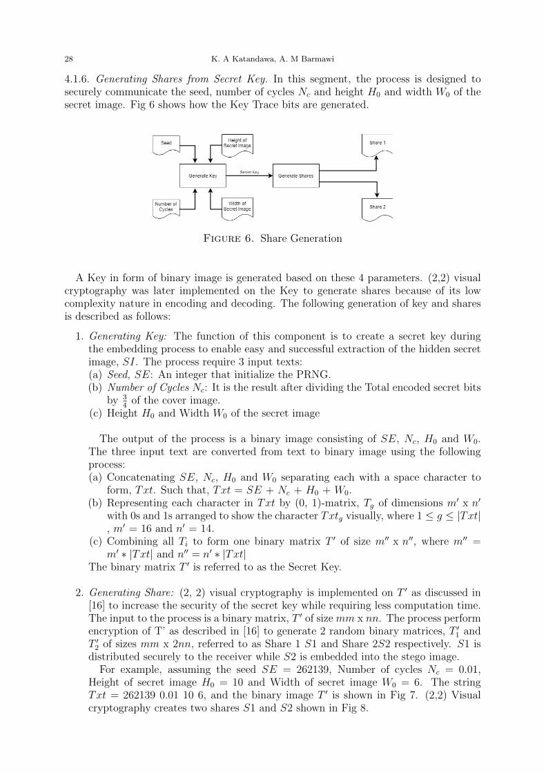
4.2. Overview of Extraction Phase. In this section the extraction process is discussed.The process aim to retrieve the embedded secret message. It requires a stego image,Share 1, share 2 and the Key Trace to successfully recover the secret message. Fig 9shows how the extraction process is conducted. To begin the extraction process Share1 is overlapped/stacked with Share 2 to construct the Key. Once the key is successfullyconstructed the Seed and the number of cycles becomes visible i.e the stacked imagewill show the seed and Number of Cycles. The pseudo random number generator withthe correct seed produces integers that represent positions on the stego to extract thesecret message using the key trace. Each of the sub processes of the extraction process isdiscussed in detail as follows:
4.2.1. Generating Key. This segment discusses how the key image is regenerated using(2,2) VCS. To extract a secret message successfully, a key should be reconstructed firstbecause it possesses the seed and number of cycles used in embedding process.To recon-struct the key we overlap the extracted Share 2 and Share 1 S1 that the receiver alreadypossess. To extract S2 from input Stego image I ′′, the following process is performed:
30 K. A Katandawa, A. M Barmawi
Figure 9. Extraction Process of Proposed Method
1. Extracting encoded Share 2: To extract S2 consider all stego pixels, sp = spq, spq+1, ..., spGwhere q is the marker for starting point of embedded S2 and G =H1 ∗W1. Applyequation (19) to every sp to form a sequence of integers sl = (sl1, sl2, ..., slE) wheren = 1 and E = (H1 ∗W1)− q and sli = 1 or 0.
2. Converting each sl element to binary to form a sequence of bits sl′ = (sl1, sl2, ..., slE∗8).3. Dividing sequence st′ to nt′ blocks ct = (ct1, ct2, ..., ctN1) of length N1 where nt′ =
(H1∗W1)−qN1
4. Decoding each block ct with RM(r1, m1) as shown in section (2.2) to form messageblocks tb′ = tb′1, tb
′2, ..., tb
′k1
.5. Decomposing all message blocks tb′ to form a single linear block B.6. Using dimensions of Share 1, n” x m”, create a binary matrix/image, S2 from se-
quence B.If S2 and S1 are stacked and aligned correctly as described in [16], the Seed SE,number of cycles N ′c, and dimensions of secret image, H ′0 x W ′
0 becomes visible.
4.2.2. Generating random pixels. The purpose of this function is to generate same integervalues as in embedding process. The generated integers represent the indices/positionsof the pixels embedded with secret bits. The seed S ′ initializes Blum Blum Shrub togenerate the random sequence of integers, pp = pp1, pp2, ..., ppL as discussed in [13].
4.2.3. LSB Extraction. The purpose of this component is to extract the encoded secretbits that were embedded into less or equal to of the cover image. If the encoded bitsET are greater than 3
4∗ H1 ∗W1 then the extracted bits act as a reference to the other
bits embedded into that same pixel. But if ET are less or equal to 34∗H1 ∗W1 then the
extracted bits represent the encoded bits E ′. The extraction of LSBs is done as follows:
1. Inputting the randomly generated pixel positions pp from stego image I ′′.2. Retrieving the pixels px′ on indices pp in same order. Consider all stego pixelsps′ = ps′1, ps
′2, ..., ps
′L. Extracting the hidden bits by applying equation (19) to every
px′ to form a sequence of integers eb = eb1, eb2, ..., ebL where n = 1 and ezi = 1 or 0.3. Converting each eb′ to binary to form a sequence of bits eb′ = eb′1, eb
′2, ..., eb
′L
4.2.4. Key Trace Extraction. The purpose of this component is to extract bits that wereembedded into Agreed image A′. These bits are called the Key trace KT . This process isexecuted if and only if ET ≥ (3
4∗H1 ∗W1). In this section, a sequence of Key Trace bits
KT , is extracted from image A′ of size H2 x W2. To extract the KT bits the followingprocess was performed:
Improving Data Hiding Capacity in Code Based Steganography 31
1. Determining the block size value of ns by: ns = |KT |H2xW2
. If ns is a not an integer,then there are two sets of block sizes:
(a) Applying equation (19) to the first dnse pixels of A′, to retrieve a sequence ofintegers w′ = w′1, w
′2, ..., w
′dnse where ns = dnse.
(b) if ((H2 ∗W2) − dnse) ≥ 1, apply equation (19) to the last ((H2 ∗W2) − dnsepixels of A′, to retrieve a sequence of integers w′′ = w′′1 , w
′′2 , ..., w
′′((H2∗W2)−dne)
where ns = ns.2. Appending sequence w′′ to w′ such that ww = w′′ + w′.3. Converting all ww to binary to produce a combined sequence of bits wb = wb1, wb2, ..., wbET
called Key Trace KT .
4.2.5. Extraction process. In this component, the bits that were re-embedded on eachpixel are retrieved. This process is only executed if the secret message embedded wasgreater than the 3
4of the cover image. The process inputs Key Trace bits wb, the LSBs
extracted from the stego ez′ and reference key R. Extract the re-embedded bits as follows:
1. Dividing the Key Trace bits wb to h blocks kb = (kb1, kb2, ..., kbbNcc) and/or h′ blockskb′ = (kb′1, kb
′2, ..., kb
′Nc
), where h and h′ are defined in Theorem 4.2.2. To each created block kb, inserting wbl on first index and R on last index of the block
such that kb = (wbl, kb1, kb2, ..., kbbNcc, R) and/or kb′ = (wbl, kb′1, kb
′2, ..., kb
′Nc, R), for
1 ≤ l ≤ ET
3. Considering each of the blocks kb and kb′ , the sequence of encoded bit block Eb isdetermined using algorithm 2:
Algorithm 2: Generation of Encoded bit block
Input: Blocks kb or kb′, dNce, Number of blocks h, h′
Output: sequence of Encoded bit blocks EB1 EB ← [ ]2 j ← 13 H ← h+ h′
4 for l← 1 to H do5 while j < dNce do6 ebblj ← kblj ⊕ kblj+1.
7 Append ebblj to EB
4. Outputting a sequence of bits EB formed after decomposing all message blocks ebbto constituent bits. The sequence EB is similar to the encoded sequence bits.
4.2.6. Decoding process. In this process, the encoded bits are decoded. The decoder is re-sponsible for performing error detection and correction to each of the input bits as statedin section 2.2 .The inputs to this process are the encoded sequence bits EB, and blocklength N1. The decoding process is performed as follows:
1. Determining if 1 ≤ ET ≤ (34∗ H1 ∗ W1) then divide sequence EB to n′′ blocks
cw = (cw1, cw2, ..., cwN1) of length N1 where n′′ = (H1∗W1)−qN1
.
2. Decoding each block of cw with RM(r1, m1) Decoder as shown is section (2.2) anduse equation (15) to form message blocks mb′ = mb′1,mb
′2, ...,mb
′k1
.3. Outputting a sequence of decoded bits sb = (sb0, sb1, ..., sbY ) formed after decom-
posing all message blocks mb′ to constituent bits, such that Y = 8 ∗H0 ∗W0.
32 K. A Katandawa, A. M Barmawi
4.2.7. Reconstructing Image. In this segment, the decoded bits are reconstructed to formsecret image SI. The process inputs the decoded bits sb and the secret image dimensions,H0 x W0 from the generated Key to generate the secret image using the following process:
1. Dividing the sequences of bits sb to bytes i.e mb = mb1,mb2, ...,mb8.2. Converting each bytemb to decimal to form a sequence of integer s′ = s′1, s
′2, ..., s
′H0 x W0
where (0 ≤ s′i ≤ 255).3. From the sequence of integers s’, creating a H0 x W0 matrix that is the representation
of the secret image.
5. Security Model. In this section, the security model of the system is discussed. Itdemonstrates how the information is exchanged between the sender and recipient. Theassumption in this model is that the Agreed image A′ is communicated earlier between thesender and the receiver via a private/secure channel. The security model is divided into3 phases, Registration, Authentication and Stego exchange and are discussed as follows .
1. Registration Phase: It is the first phase of the security model. The purpose ofthis phase is to communicate S1 to receiver securely between Sender and Receiver.The Sender generates two shares S1 and S1 from the Secret Key using (2, 2) VCS asdiscussed in section (4.2). The Sender possesses S2 and transmit S1 to the Receivervia a secure channel. Upon receiving S1, the Receiver sends back a confirmationmessage ”RECEIVED”.
2. Authentication Phase: It is the second phase of the security model. In this phase,communication is done via public channel. Its function is to verify the validity ofthe Receiver. The Sender transfers S2 to the Receiver, and upon receiving S1, theReceiver superimpose the two shares and extract the seed visually as discussed insection (2.3.1). The extracted seed is hashed using SHA 512 algorithm to form H1.The Receiver transmits H1 to Sender so that the validity of the Receiver is verified.The Sender uses the same Hash algorithm (SHA 512) to hash the seed that he/shepossesses to form H2. Upon receiving H1, the Sender verifies if H1 and H2 are thesame. If the two hash values are equal then the Receiver is valid and if not thenhe/she is not.
3. Stego exchange: It is the last phase of the security model. The purpose of thisphase is to communicate a Stego image between two users. It only occurs if and onlythe Receiver has been authenticated in phase 2. It involves all the steps as describedin sections 4.5 and 4.6.
6. Experiments and Discussion. This section discusses the result of the experimentsthat were conducted for evaluating the capacity, robustness and imperceptibility as wellas the analysis of results.
6.1. The Experiment result for Capacity Evaluation. The objective of the experi-ment was to determine the embedding capacity of the cover images for both Molaei’s andproposed methods. The experiment was conducted to 30 grayscale cover images of size(512 x 512) of different histograms. Both methods were used to embed 20 grayscale secretimages of different sizes on each cover image. The embedding capacity EC is expressedas percentage and is calculated using equation (38) in [12]:
EC =|S|
H ∗W(38)
where |S| is the number of secret bits embedded on a cover image of height H and widthW. Table 1 summaries the results of the experiment.
Improving Data Hiding Capacity in Code Based Steganography 33
6.2. The Experiment result for Imperceptibility Evaluation. The objective of theexperiment was to evaluate the visual quality of the stego images for both Molaei’s andproposed methods.
Table 1. A Capacity Comparison between Proposed Method and Previousmethod
The experiment was conducted similarly to section 6.1. PSNR criterion was used toevaluate the visual quality, and is calculated using equation (39) in [12]:
PSNR = 10log102552
MSE(39)
where MSE refers to the difference between the pixel values of Cover and stego images.It is calculated using equation (40) in [12]:
MSE =1
H ∗W
H∑i=1
W∑j=1
(Iij − I ′ij)2 (40)
where Iij and I ′ij are the pixels values of cover and stego image respectively. The lowerthe MSE value means the difference between the stego and cover is lower and as a result,the higher the PSNR value which is more desirable in steganography. Table 1 summariesthe results of the experiment.
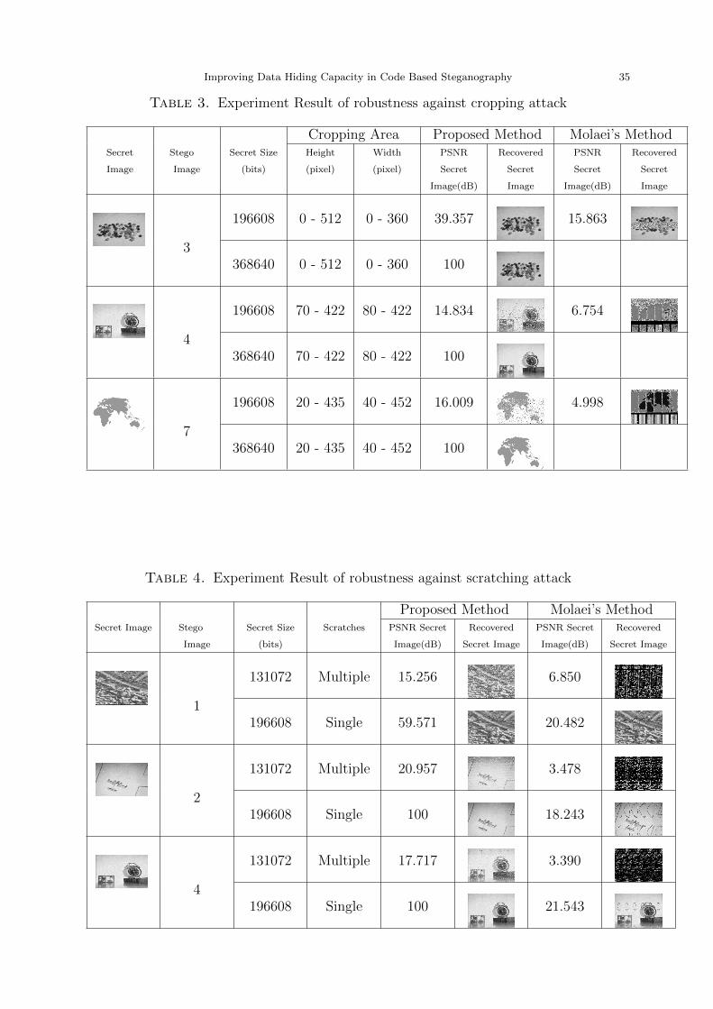
6.3. Experiment result for robustness against attacks. In this experiment a set of20 different images were used as the cover images and another set of 20 different images assecret images. Each cover image was embedded with 33 different sizes of each secret image.The stego image formed at each experiment was subjected to noise, (Gaussian Noise, Saltand Pepper Noise, and Speckle Noise), Cropping, Scratching(Single and Multiple), JPEGcompression. The experiment was performed to recover the hidden secret image from theattacked stego image. The results of the experiments are shown in Table 2, 3, 4 and 5respectively.
34 K. A Katandawa, A. M Barmawi
Table 2. Experiment Result of robustness against noise attack
Proposed Method Molaei’s MethodSecret
Image and
Size
Stego
Image
Noise
Attacks
PSNR
Attacked
Stego(dB)
PSNR
Secret
Image(dB)
Recovered
Secret
Image
PSNR
Attacked
Stego(dB)
PSNR
Secret
Image(dB)
Recovered
Secret
Image
Gaussian:Mean
0 Variance
0.01
20.218 9.359 20.213 9.336
20 SaltnPepper:
Density
0.05
18.353 100 18.271 28.390
15360 Speckle:
variance
0.04
21.350 9.324 21.357 9.654
Gaussian:
Mean 0
Variance
0.1
11.453 17.176 11.354 9.276
11 SaltnPepper
: Density
0.5
8. 240 28.124 8. 216 11.505
196608 Speckle:
variance
0.4
11.912 17.690 11.620 9.842
Stego Gaussian:
Mean 0
Variance
0.1
11.454 100
11 SaltnPepper
: Density
0.5
8. 240 100
368640 Speckle:
variance
0.4
11.872 100
Improving Data Hiding Capacity in Code Based Steganography 35
Table 3. Experiment Result of robustness against cropping attack
Cropping Area Proposed Method Molaei’s MethodSecret
Image
Stego
Image
Secret Size
(bits)
Height
(pixel)
Width
(pixel)
PSNR
Secret
Image(dB)
Recovered
Secret
Image
PSNR
Secret
Image(dB)
Recovered
Secret
Image
196608 0 - 512 0 - 360 39.357 15.863
3368640 0 - 512 0 - 360 100
196608 70 - 422 80 - 422 14.834 6.754
4368640 70 - 422 80 - 422 100
196608 20 - 435 40 - 452 16.009 4.998
7368640 20 - 435 40 - 452 100
Table 4. Experiment Result of robustness against scratching attack
Proposed Method Molaei’s MethodSecret Image Stego
Image
Secret Size
(bits)
Scratches PSNR Secret
Image(dB)
Recovered
Secret Image
PSNR Secret
Image(dB)
Recovered
Secret Image
131072 Multiple 15.256 6.850
1196608 Single 59.571 20.482
131072 Multiple 20.957 3.478
2196608 Single 100 18.243
131072 Multiple 17.717 3.390
4196608 Single 100 21.543
36 K. A Katandawa, A. M Barmawi
Table 5. Experiment Result of robustness against JPEG compression
Proposed Method Molaei’s MethodSecret
Image
Stego
Image
Secret Size
(bits)
PSNR
Attacked
Stego(dB)
PSNR
Secret
Image(dB)
Recovered
Secret
Image
PSNR
Attacked
Stego(dB)
PSNR
Secret
Image(dB)
Recovered
Secret
Image
92160 42.699 11.176 42.351 8.175
5196608 42.696 15.382 42.340 8.157
92160 42.680 12.119 42.455 9.156
3196608 42.675 17.831 42.465 9.108
92160 43.388 11.820 44.279 8.909
2196608 43.391 18.565 44.598 8.779
Table 6. Experiment Result of Steganalysis
Molaei’s Method Proposed MethodCover
Image
Secret Size
(bits)
True P
value
Estimated
P value
True P
value
Estimated
P value
15360 0.058594 0.053251 0.128125 0.101454
196608 0.75 0.47209 0.409375 0.395543
368640 0.405469 0.39146
15360 0.058594 0.053862 0.128125 0.10089
196608 0.75 0.4199 0.409375 0.392145
368640 0.405469 0.38146
15360 0.058594 0.052611 0.128125 0.09089
196608 0.75 0.4012 0.409375 0.38795
368640 0.405469 0.38001
6.4. Experiment Results for Steganalysis. In this experiment a set of 20 differentimages were used as the cover images and another set of 20 different images as secret
Improving Data Hiding Capacity in Code Based Steganography 37
images. Each cover image was embedded with 33 different sizes of each secret image.Each stego image formed at each experiment was subjected to steganalysis attacks todetect and estimate the embedded secret message size. The proposed steganalysis method(Triples) estimated the value of p (fraction of the secret message hidden in a given coverimage). The results of the experiment is shown in the Table 6.
7. Analysis of Experiment Results. In this section the analysis of experiment resultsis done. Analysis is performed on Capacity, Imperceptibility, robustness and steganalysis.
7.1. Analysis of Capacity and Imperceptibility between proposed and Molaei’sMethods. According to the experiment results of capacity obtained, Fig 10 shows thatfor each secret message size the proposed method achieves a greater embedding capacitythan Molaei’s method. This occurred because of the error correction code and the multipleembedding method adopted in the proposed method. Reed Muller code (1, 4) used inproposed method encodes a message block of size 5 into a code-word of size 16 thereforeencoding expansion is 16
5= 3.2. Molaei’s method implemented Reed Muller (1,3) and
Reed Muller (2,5) codes which encodes a message block of size 4 or 8 into a code-word ofsize 8 or 16 and its encoding expansion is 8
4= 2. Clearly the expansion of the proposed
method is higher than Molaei’s method. For any given secret message size the proposedmethod encodes a message to code-words of greater size than the previous method by anexpansion factor of 3.2
2= 1.6.
The proposed method introduced multiple embedding method which only embeds mes-sage into the first LSB of some pixels unlike Molaei’s method which is limited to embed-ding data only on the first and second LSBs of the cover’s pixels. In multiple embeddingmethod the LSB of each pixel of the cover image is embedded more than once. The em-bedding capacity is increased because the LSB of each pixel can be embedded more than1 message bit. The proposed method achieved maximum embedding capacity of 450(%),while Molaei’s method has a maximum capacity of 150(%) which is 450
150= 3 times less
than the Proposed Method. Its maximum embedding capacity of 150(%) is achieved byembedding both the first and second LSB of each pixel of the cover image.
Figure 10. The experiment result of embedding capacity comparison be-tween Molaei’s Method and the Proposed Method
38 K. A Katandawa, A. M Barmawi
Embedding into the second LSBs as suggested by Molaei increases the Mean SquareError between the cover and the resulting stego image. This decreases the overall imagequality (PSNR value) of the final stego to (48dB). However, the proposed method used 3
4of the pixels of each cover image and re-embedded the remaining secret bits into the samepixels that were embedded before. This guarantees that a maximum of (3
4∗ 512 ∗ 512) =
196608 LSBs of the cover pixels will only be changed after embedding any secret messagesize. These small changes leads to a low Mean Square Error therefore multiple embeddingmethod achieves high capacity accompanied with a good visual quality ≥51dB. WhileMolaei’s method has ≤48dB.
7.2. Analysis of Robustness against Attacks between Proposed and Molaei’smethods. Tables 2, 3, 4 and 5 shows that the proposed method has better error correctioncapability as compared to Molaei’s method. This occurred because of the different errorcorrection codes implemented in proposed and Molaei’s method. The proposed methodimplemented Reed Muller (1,4) codes.
From definition (2.1), Reed Muller (1,4) code encode a message of size (k): k =∑ri=0
(mi
)=∑1
i=0
(4i
)=(40
)+(40
)= 5 bits. And a code word of size,N = 2m = 24 = 16
bits. The maximum number of error bits this code can correct: t =⌊24−1−1
2
⌋= 3 bits.
Error Correction capability, Ec = number of corrected bitstotal bits
= 316
= 18.75(%). While Molaei’smethod implemented Reed Muller (1,3) codes for first LSB embedding and Reed Muller(2,5) codes for second LSB embedding. The code has message sizes (k), 4 and 16 bitsrespectively. These are encoded to codewords of sizes, N, 8 and 32 bits. These codes can
correct a maximum of t1 =⌊23−1−1
2
⌋= 1 error bit and t2 =
⌊25−2−1
2
⌋= 3 error bits for
RM(1,3) and RM(5,2) respectively.Therefore the error correction capacity for each of thecodes is 12.5 (%) and 9.38 (%) respectively. Therefore the proposed method suggested anerror correction code that outperforms the one suggested in Molaei’s method.
The Key Trace embedded into the Agreed image play a major role in error correction.The Key Trace is free from any attacks and helps increasing the error correction capabilityduring extraction process. The secret data size increases as the key trace data also
increases, KT = |S|∗Nk− 3
4∗ H ∗ W , where |S| is the size of secret in bits, N is the
block size, H and W is the Height and Width of the cover image.
7.2.1. Analysis of Robustness against Noise Attacks between Proposed and Molaei’s meth-ods. The experiment results shows that the secret size and contrast are two main factorsthat affects the recovering of secret images. The Proposed Method out performs Mo-laei’s method and successfully recovers the secret image from stego images under Saltand Pepper: Variance 0.04 for smaller secret message sizes. This occurred because Saltand Pepper has a smaller variance hence makes fewer distortions on the stego such thateach retrieved codeword has number of errors t ≤ 3 bits. These are easily correctableby the proposed Reed Muller code. While Molaei’s method recovered poor quality secretimages because the implemented code, Reed Muller (1,3), can correct only 1 error on eachcodeword block yet the recovered code words have ≥ 1 errors and are not correctable.
Under Gaussian and Speckle attacks, these small secret sizes cannot be retrieved (notvisible) even at any level of contrast for both Molaei’s and Proposed Methods. This iscaused by the large number changes on pixel values of the stego which results in retrievedcodewords with a number of errors greater than t. However, for the secret images withlow contrast, the proposed method has better PSNR values than Molaei’s method becauseit has a (18.75(%) - 12.5(%)) = 6.25(%) better error correction capability than that ofMolaei’s.
Improving Data Hiding Capacity in Code Based Steganography 39
Considering secret images of size ≥ 107520 bits, the Proposed method out performsMolaei’s method for all Noise attacks. The Proposed method can fully recover the secretmessages (100dB) of any level of contrast under Salt and Pepper: Variance 0.04 whileMolaei’s method cannot ≤ 40dB. This occurred because for each block of the messageto be re-embedded into each LSB of the pixel, only 1 bit of the block is embedded andthe remaining block is represented as Key Trace and this Key Trace cannot be corruptedby any kind of attack. This increases the error correction capability of the code sincefewer bits will be corrupted as the message size increases. This causes t to approach 3correctable bits rapidly. However both Methods cannot recover fully the secret imageunder Salt and Pepper: Variance 0.4 and Gaussian Noises and Speckle Noise but theProposed method recovers secrets with better visibility than Molaei’s method.
Considering secret images of size ≥ 368640 bits, the Proposed method performs best forall Noise attacks. It can successfully retrieve any secret image ≥ 368640 bits of any levelof contrast. In this case the code is able to correct all corrupted blocks. At this size thenumber of errors in each block of code word is exactly t ≤ 3 and is therefore correctablesuccessfully.
As the size of the secret image increases, the error correction capability of the pro-posed error correction code increases thereby increasing the recovered secret image qual-ity, PSNR. The Key Trace embedded into the Agreed image is free from any Noise attacksand helps increasing the error correction capability during extraction process. The qualityof the retrieved secret image increases as the size of secret image increases.
7.2.2. Analysis of Robustness against Cropping Attacks between Proposed and Molaei smethods. For reduced cropping regions, the proposed method achieves better results thanMolaei s method. Although it cannot recover the secret images fully but the secret imageis quite visible compared to Molaei s method. This occurred because the number of errorsin most retrieved codewords caused by the cropping approaches t ≈3. There are greaterthan the minimum number of correctable errors for each codeword, therefore cannot befully correctable.
Considering medium sized secrets within [46080 − 353280] bits, the Proposed methodretrieves better quality secret images as compared to Molaei s method. Molaei s methodstruggled to recover low contrast secret images, most of which are highly noisy, not visibleand contains large black regions. As the size of the secret image increases, the errorcorrection capability of the proposed error correction code increases thereby increasingthe recovered secret image quality, PSNR.
Considering large secret sizes within [368640 − 384000] bits, the Proposed Methodsuccessfully recovers the hidden secret image under and any cropping region size attack.As the secret image size increases the retrieved secret image quality drastically increasesunder any of the applied cropping region attacks. This occurred because of the PRNGadopted to randomly embed and extract the secret images to avoid burst error which aremore common in Molaei s method.
7.2.3. Analysis of Robustness against Scratching Attacks between Proposed and Molaeis methods. Based on Table 5, the proposed method can successfully recover the secretmessage on Single Scratching attacks for all high contrast secret image of any size. Thisbecause a single scratch alters few pixels on the stego and since the secret data wasembedded randomly, therefore the errors does not belong to a single code word. Thereforeburst errors are not encountered in the proposed method than in Molaei s method whichembedded data serially. The number of errors in each retrieved codeword is t ≤3 which is
40 K. A Katandawa, A. M Barmawi
correctable. Molaei s method cannot recover fully secrets because as the embedded areaon the cover increases, the number of alterations caused by scratching also increases. Thepossibility of retrieving code words with increased errors t ≥1 and burst errors increases.
Considering Multiple scratch attacks, the Proposed Method cannot successfully retrieveall smaller secret image (≤ 353 280) bits. This is because all of the secret data is embeddedinto the cover and scratching alters a larger part if not all of the data thereby increasingthe value of t error bits. And if t is greater than 3 then the code words cannot becorrected successfully. The quality of the retrieved secret image increases as the size ofsecret image increases. This is because as the secret data size increases the key trace dataalso increases.
However, large secret sizes (≥ 368640 bits) can be retrieved by the Proposed Method.This is because the size of Key trace bits in each retrieved codeword increased and t ≤3. When t ≤ 3 the codeword is correctable. Molaei s method cannot retrieve any secretimages under Multiple Scratches because the scratches caused many alterations such thatfor every retrieved code word the number of errors t1 ≥ 1 , t2 ≥ 3 and are not correctable.It also causes large burst errors which are not correctable with the suggested error cor-rection code.
7.2.4. Analysis of Robustness against JPEG compression Attacks between Proposed andMolaei s methods. :Table 6 shows that Molaei s method cannot successfully recover any secret message sizeof any level of contrast under JPEG compression attacks. The recovered secret imageshave low PSNR values and not not visible. This was caused by the large changes in pixelvalues caused by JPEG compression which affect the embedded pixel values. They resultin many alterations of the stego pixels such that for every retrieved code word the numberof errors t1 ≥ 1 , t2 ≥ 3 and are not correctable. It also causes burst errors which are notcorrectable with the suggested Reed Muller codes.
On the other hand, the Proposed method can only retrieve successfully large secretimages of sizes ≥ 368640 bits. This occurred because the size of Key trace bits in eachretrieved codeword increased and t ≤ 3. When t ≥ 3 then the codeword is correctable.However, the proposed method performs poorly for smaller secret images. This occurredbecause the value of Key trace for smaller secret data is zero which means error correctionwill rely only on the data retrieved from the stego. And this data is highly altered ordistorted by JPEG compression, therefore the number of errors t ≥ 3 and is not cor-rectable. The retrieved secret images of size (≥ 92160) bits are quite visible and the noiseon the images decreases as the size of the secret image increases. Therefore, the retrievedsecret image PSNR value under proposed method increases as the size of the secret imageembedded increases.
7.3. Steganalysis for Proposed and Molaei’s method. An improved Steganalysismethod proposed by Andrew D. Ker[1], called Triples Analysis. It is a detector used forsimple LSB steganography in digital images. It uses the structural and combinatorialproperties of the LSB embedding method to detect and estimate the length of the hiddenmessages. Triples has proved to be a more powerful and sensitive detector than otherstructural detectors such as RSA, SPA etc. It utilizes the effects of LSB changes onarbitrary groups of samples ie 3-tuples of pixel groups. Triples assumes that the Coverimage is fixed and a random hidden message is embedded.
Improving Data Hiding Capacity in Code Based Steganography 41
Suppose the hidden message has length 2pN , where 0 ≤ p ≤ 0.5 is unknown to thedetector, is embedded using LSB embedding of a random selection of samples independentof the content of the cover or hidden message[1] . A trace set Cm,n is created in whichall pixel samples s1, , sN are drawn, where n, m > 0 and N is number samples. Theprobability of transition from one trace subset to another is pi(1− p)(3−i), where i is thelength of the shortest path between them. The trace set and subsets are constructed usingequations (41), (42) and (43) in [1].
Cm1,...,mg−1,ng−1 = (s1, , sg) ∈ T |[si+1
2] = [
si2
] +mi and [si+2
2] = [
si+1
2] + nifor each1 ≤ i ≤ g
(41)
Em1,...,mg−1,ng−1 = (s1, , sg) ∈ T |si+1 = si +mi and si+2 = si+1 + ni with mi even (42)
Om1,...,mg−1,ng−1 = (s1, , sg) ∈ T |si+1 = si +mi and si+2 = si+1 + ni with mi odd (43)
When a single sample has the LSB altered a tuple transitions to either of the followingtrace subsets E2m,2n, O2m,2n, E2m+1,2n−1, O2m,2n−1, E2m,2n+1, O2m−1,2n+1, E2m+1,2n, andO2m−1,2n. Given a stego image, consider each trace set Cm,n in turn and count the tracesubsets to make a vector x′ using equations (44) in [1].
x′′ = T−13 x′ (44)
Then we can hypothesize a value of p and form estimates for the sizes of the tracesubsets of the cover image using the transition matrix, T3. The parity symmetry ischecked if it s true for both covers and also stego images when both m and n are evenor equal. Considering one case of parity symmetry, e2m+1,2n+1 = o2m+1,2n+1. To use thegeneralized framework to make an estimate of p, we compute error terms for each mand n, εm,n = e′2m+1,2n+1 − o′2m+1,2n+1. Then we find the value of p which minimizes thesum-square of the errors. Firstly, using the transition matrix, the number of errors isdetermined by
(45)Where di are the differences of various combinations of e2m+i,2n+i and o2m+1,2n+1 subsets.
Find the value of q to minimize S(q) =∑
m,n ε2m,n. We have
S(q) =1
64
∑m,n
c20+q(2c0c1)+q2(2c0c2+c
21)+q
3(2c0c3+2c1c2)+q4(c22+2c1c3)+q
5(2c2c3)+q6(c23)
(46)Differentiating the above equation (47) and solving for q will give up to 5 roots for q. Allroots inside the range (−10, 10/11) are discarded because they will give wrong estimatesof p outside (−0.05, 0.55)). Substitute the remaining roots back into (47) to determinethe location of the minimum q′. Finally, the estimate of p, p′ = 1
2(1− 1
q).
Triples has been implemented to determine how the proposed and Molaei s methodperform under steganalysis. Triples was able to detect the presence of a hidden messagein both the proposed and Molaei s method for every Cover image used. The marginbetween the estimated and true p value increases as the length of the hidden secretmessage increases as shown in Table 6.
7.3.1. Analysis of Triples Results using Proportion. Proportion was used to compare theperformance of Molaei s method and proposed method under steganalysis. Using the
42 K. A Katandawa, A. M Barmawi
results of True p value (Tp) and Estimated p value (Ep) for each secret message sizerecorded on Table 7, proportion P was calculated as follows:
P =Ep
Tp(47)
A larger value of P means that the estimated p value is closer to the true p value. Itmeans that the probability of attacker to predict the true p value is high. A smaller Pvalue means that there is a bigger difference between the estimated p value from the truevalue so the attacker cannot easily predict the true p value. A high value of proportionmeans that the there is a smaller difference between the Estimated p value and the Truep value. That means the Triples estimated the p value almost accurately. For smallersecret sizes, the proportion values of the proposed method is always smaller than Molaeis method. This is caused by the high expansion rate of 3.2 in Reed Muller (1,4) code usedin proposed method compared to 2 in Reed Muller(1,3) code used in Molaei s method.This means that for any given secret message size, the proposed method results in a largersecret size to be embedded than Molaei s method. And Triples method has been provedto be highly sensitive to smaller secret sizes than large ones, hence the proposed methodperforms better than Molaei s method.
Figure 11. A comparison of Steganalysis results for Molaei s method andproposed method based on proportion
The proportion values of the proposed method decreased rapidly for secret sizes [61440– 368640 bits] while the proportion values of Molaei s method decreased steadily as shownon Fig 11. This occurred because of the Multiple embedding method adopted. Multipleembedding re-substitutes different secret bits on LSB of pixels that have already beenembedded, such that at the end of the embedding process each pixel has either 1 changeor same LSB as of the original/initial LSB. Triples method can only detect the messagelength based on the last embedding cycle. Due to this, there is an increase in True p valuewhile the Estimated value is ≈ 0.3. It is because of this that the difference between theproportion values of proposed and Molaei s methods is very large. Therefore the proposedmethod is less detectable under steganalysis than Molaei s method.
8. Conclusions. A Multiple embedding method was proposed to achieve a high embed-ding capacity (450%) in Code based steganography scheme. The method contributed to animproved visual quality (≥ 51dB) of the Stego image that ensured high Imperceptibility.Furthermore, Multiple embedding had a huge impact on the overall robustness of Codebased steganography schemes against noise, scratching, cropping and jpeg compression
Improving Data Hiding Capacity in Code Based Steganography 43
attacks. All extracted secret images had an improved visual quality reaching to 100dBfor high embedding capacity (450%) while Molaei s method achieved very low qualityextracted secret images. The security of the hidden secret message was also improved byembedding secret message randomly across the image by using a PRNG.
REFERENCES
[1] A. D. Ker, A general framework for structural steganalysis of lsb replacement, In InternationalWorkshop on Information Hiding, pp. 296-311. Springer, 2005.
[2] A. M. A.-A. Selami and A. F. Fadhil, A study of the effects of gaussian noise on image features,Kirkuk University Journal for Scientific Studies, vol. 11, no. 3, pp. 152-169, 2016.
[3] A. Molaei, M. Sedaaghi, and H. Ebrahimnezhad, Steganography scheme based on reed-muller codewith improving payload and ability to retrieval of destroyed data for digital images, AUT Journalof Electrical Engineering, vol. 49, no. 1, pp. 53-62, 2017. doi: 10.22060/eej.2016.814.
[4] B. Cooke, Reed-muller error correcting codes, MIT Undergraduate Journal of Mathematics, pp.21-26, 1999.
[5] C.-C. Thien and J.-C. Lin, A simple and high-hiding capacity method for hiding digit-by-digit datain images based on modulus function, Pattern recognition, vol. 36, no. 12, pp. 2875-2881, 2003.
[6] D. Taranovsky. Data Hiding and Digital Watermarking, pp. 387-399. Springer Berlin Heidel-berg, Berlin, Heidelberg, 2012. ISBN 978-3-540-79567-4. doi: 10.1007/978-3-540-79567-4 31. URLhttps://doi.org/10.1007/978-3-540-79567-4 31.
[7] M.A. Hassan and M.A. Khalili, Self watermarking based on visual cryptography, In Proceedings ofWorld Academy of Science, Engineering and Technology, vol. 8, pp. 159-162, 2005.
[8] H. V. Desai, Steganography, cryptography, watermarking: A comparitive study, Journal of GlobalResearch in Computer Science, vol. 3, no. 12, pp. 33-35, 2013.
[9] J. C. Judge, Steganography: past, present, future. Technical report, Lawrence Livermore NationalLab., CA (US), 2001.
[10] J. Van Lint and G. Van der Geer, Introduction to coding theory and algebraic geometry, vol. 12,Birkhauser Boston, Inc. Secaucus, NJ, USA, 2012. ISBN0817622306.
[11] M. Mansourpour, M. Rajabi, and J, Blais, Effects and performance of speckle noise reduction filterson active radar and sar images, In Proc. ISPRS, vol. 36, pp. W41, 2006.
[12] M. V. R. CH et al., Medical image watermarking schemes against salt and pepper noise attack,International Journal of Bio-Science and Bio-Technology, vol. 7, no. 6, pp. 55-64, 2015.
[13] P. Junod, Cryptographic secure pseudo-random bits generation: The blum-blum-shub generator,1999.
[14] R. Crandall, Some notes on steganography. Posted on steganography mailing list, pp. 1-6, 1998. URLhttp://os.inf.tu-dresden.de/ westfeld/crandall.pdf.
[15] S. B. Wicker, Error control systems for digital communication and storage, vol. 1, Prentice hallEnglewood Cliffs, 1995.
[16] S. Cimato and C.-N. Yang, Visual cryptography and secret image sharing, CRC press, FL, USA,2017. ISBN 978-1-4398-3721-4.
[17] S. Lin and D. J. Costello, Error control coding, Prentice-Hall, Inc. Upper Saddle River, NJ, USA,2001. ISBN 0-13-200809-2.
[18] S. Kaisar and J. A. Mahmud, Salt and pepper noise detection and removal by tolerance based selectivearithmetic mean filtering technique for image restoration, International Journal of Computer Scienceand Network Security, vol. 8, no. 6, pp. 271-278, 2008.
[19] Y. Zhang, J. Jiang, Y. Zha, H. Zhang, and S. Zhao, Research on embedding capacity and efficiencyof information hiding based on digital images, International Journal of Intelligence Science, vol. 3,no. 2, pp. 77, 2013.