39
Improving System Protection Reliability and Security Steve Turner Senior Application Engineer Beckwith Electric Company Minnesota Power Systems Conference 2015
Improving System Protection
Reliability and Security
Steve Turner
Senior Application Engineer
Beckwith Electric Company
Minnesota Power Systems Conference 2015

Introduction
• Summarize conclusions from NERC 2013 Reliability Report
• Analyze Generator Differential Protection Misoperation
• Analyze 27TN Misoperation
(3rd Harmonic Neutral Undervoltage)
• Analyze Incorrect Phase Rotation Settings
• Corrective Actions
• Conclusions
NERC released an official report in 2013 that featured
statistics for misoperations across the entire country.
Introduction
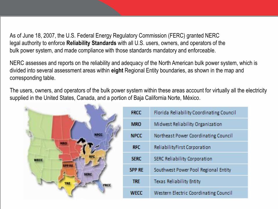
As of June 18, 2007, the U.S. Federal Energy Regulatory Commission (FERC) granted NERC
legal authority to enforce Reliability Standards with all U.S. users, owners, and operators of the
bulk power system, and made compliance with those standards mandatory and enforceable.
NERC assesses and reports on the reliability and adequacy of the North American bulk power system, which is
divided into several assessment areas within eight Regional Entity boundaries, as shown in the map and
corresponding table.
The users, owners, and operators of the bulk power system within these areas account for virtually all the electricity
supplied in the United States, Canada, and a portion of Baja California Norte, México.

Major Events Ranked > 10 NERC Daily Severity Risk Index (Benchmarks)
• 1989 Quebec Solar Flare (3)
• 1996 Western Disturbance (7)
• 2003 Eastern Interconnection Blackout (8)
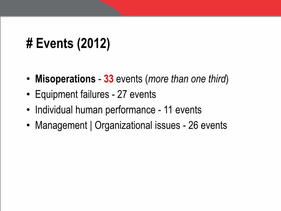
# Events (2012)
• Misoperations - 33 events (more than one third)
• Equipment failures - 27 events
• Individual human performance - 11 events
• Management | Organizational issues - 26 events
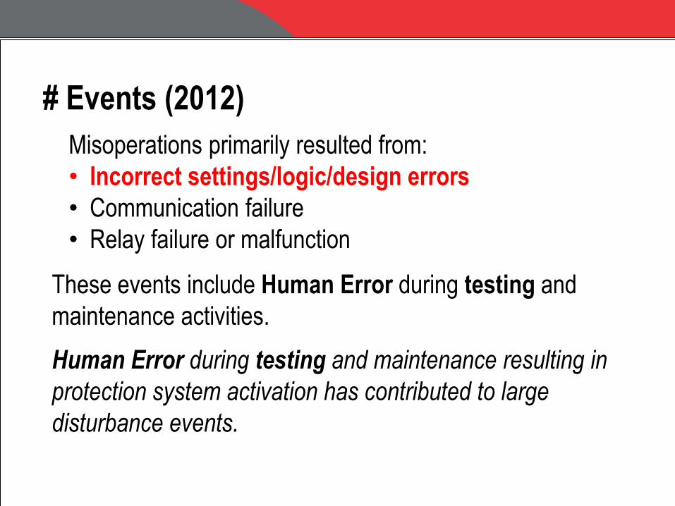
Misoperations primarily resulted from:
• Incorrect settings/logic/design errors
• Communication failure
• Relay failure or malfunction
# Events (2012)
These events include Human Error during testing and
maintenance activities.
Human Error during testing and maintenance resulting in
protection system activation has contributed to large
disturbance events.
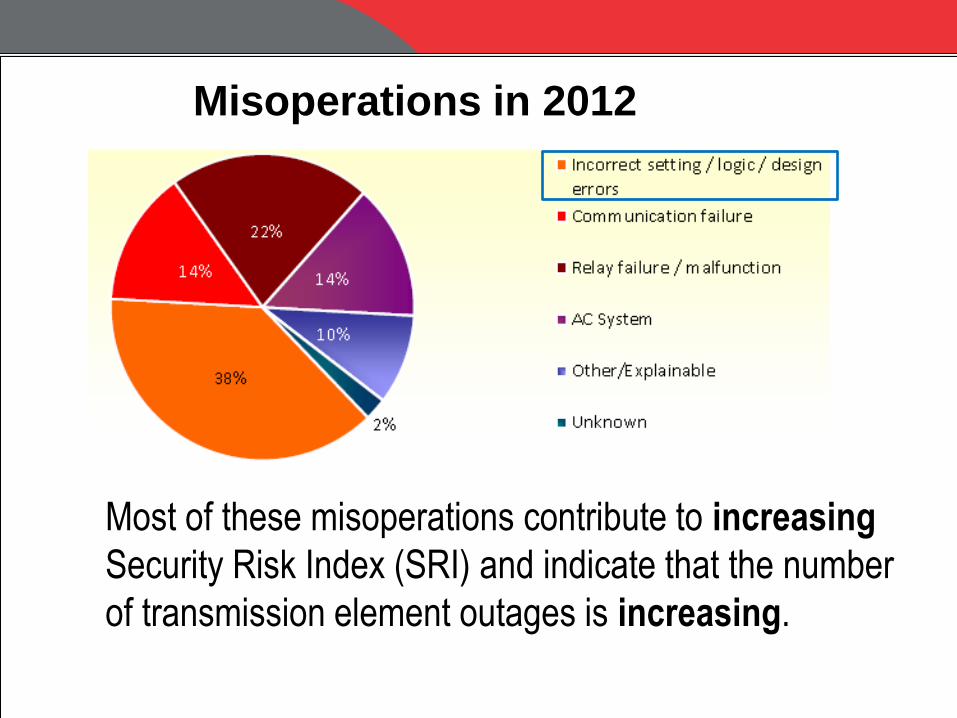
Misoperations in 2012
Most of these misoperations contribute to increasing
Security Risk Index (SRI) and indicate that the number
of transmission element outages is increasing.
Corrective Actions (1)
Applications requiring coordination of functionally different relay elements should be avoided. This type of coordination is virtually always problematic and is the cause of numerous misoperations reported in the study period.
Corrective Actions (2) Misoperations due to setting errors can be reduced – several techniques include:
Peer reviews
Increased training
More extensive fault studies
Standard setting templates for standard schemes
Periodic review of existing settings when there is a change in system topography
Greater Complexity = Greater Risk of Misoperation
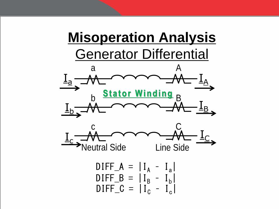
Misoperation Analysis
Generator Differential a A
b B
c C
Neutral Side Line Side
Ia IA
Ib IB
Ic IC
S t a t o r W i n d i n g
DIFF_A = |IA – Ia| DIFF_B = |IB – Ib| DIFF_C = |IC – Ic|
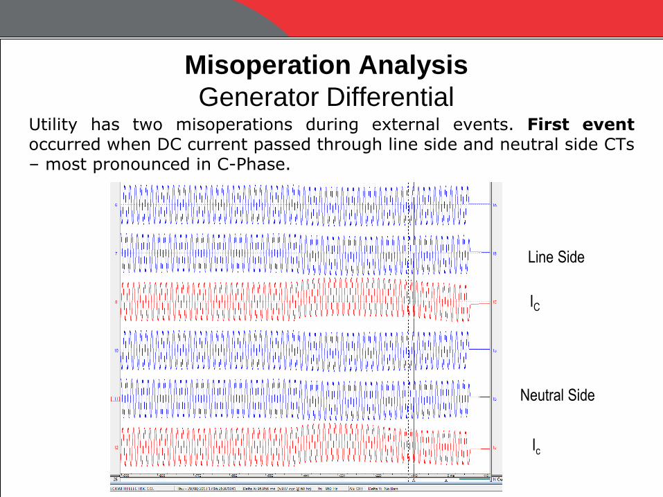
Misoperation Analysis
Generator Differential Utility has two misoperations during external events. First event occurred when DC current passed through line side and neutral side CTs – most pronounced in C-Phase.
Line Side
Neutral Side
IC
Ic
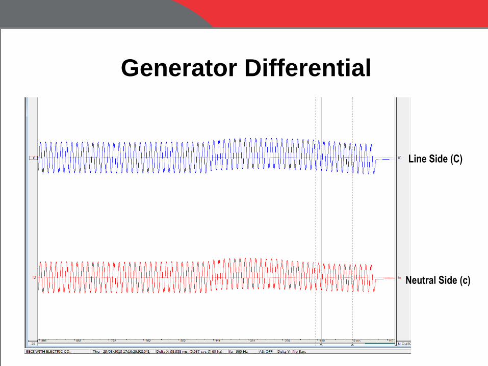
Generator Differential
Line Side (C)
Neutral Side (c)

Generator Differential
Line Side (C)
Neutral Side (c)
Differential (C)
0.578 amps

Generator Differential
C-Phase
(lower knee point voltage)
A-Phase
Excitation Characteristics for Neutral Side CTs (A and C Phases)
Vknee < 100 volts
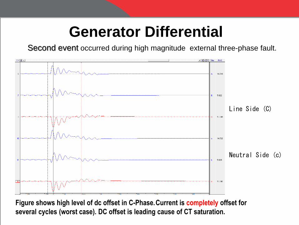
Second event occurred during high magnitude external three-phase fault.
Generator Differential
Line Side (C)
Neutral Side (c)
Figure shows high level of dc offset in C-Phase. Current is completely offset for
several cycles (worst case). DC offset is leading cause of CT saturation.
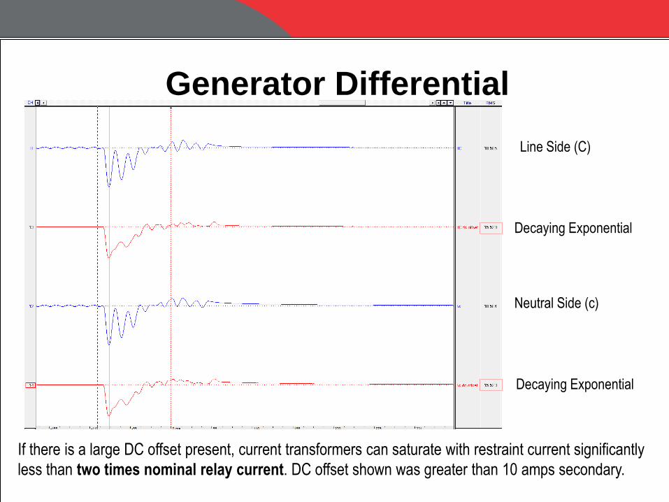
Generator Differential
Line Side (C)
Neutral Side (c)
Decaying Exponential
Decaying Exponential
If there is a large DC offset present, current transformers can saturate with restraint current significantly
less than two times nominal relay current. DC offset shown was greater than 10 amps secondary.
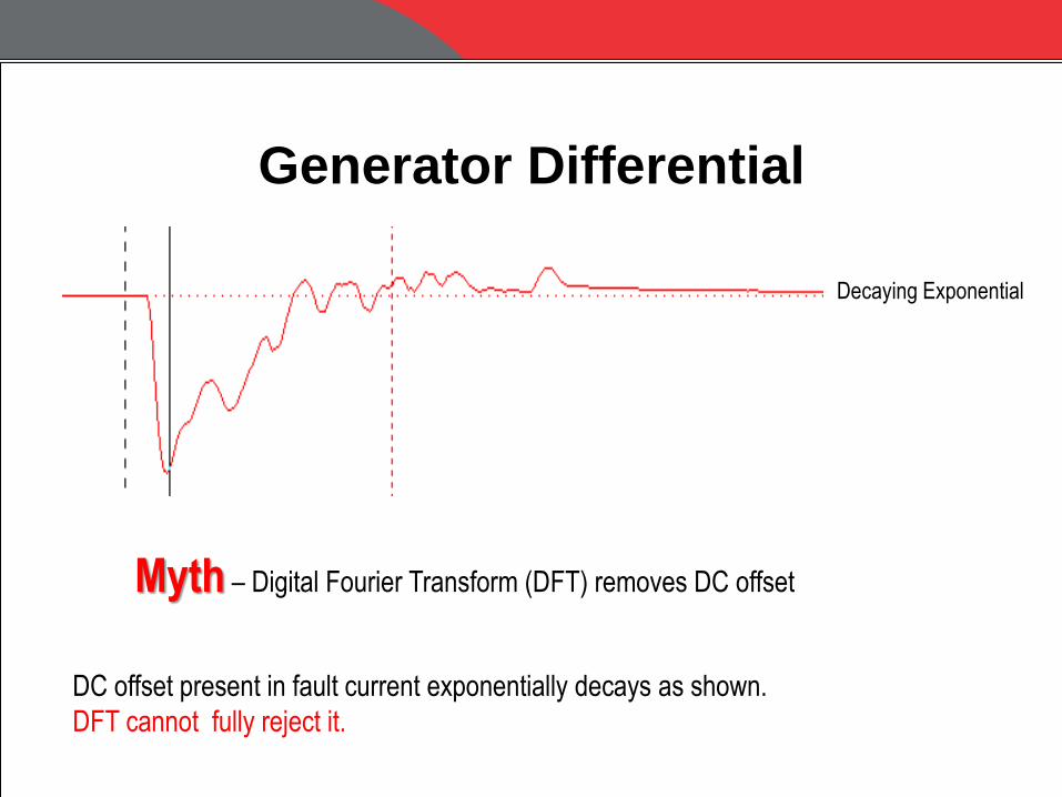
Generator Differential
Decaying Exponential
Myth – Digital Fourier Transform (DFT) removes DC offset
DC offset present in fault current exponentially decays as shown.
DFT cannot fully reject it.
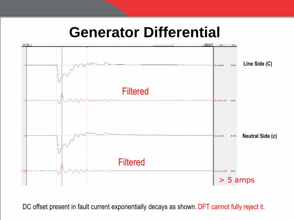
DC offset present in fault current exponentially decays as shown. DFT cannot fully reject it.
Generator Differential
Filtered
Filtered
> 5 amps
Line Side (C)
Neutral Side (c)
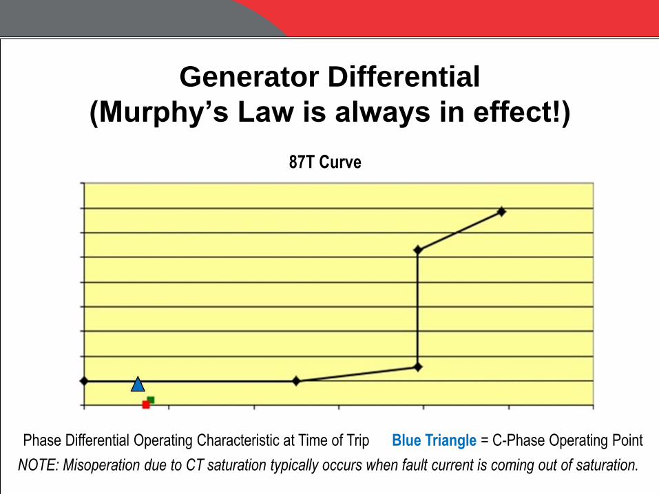
Generator Differential
(Murphy’s Law is always in effect!)
Phase Differential Operating Characteristic at Time of Trip Blue Triangle = C-Phase Operating Point
NOTE: Misoperation due to CT saturation typically occurs when fault current is coming out of saturation.
87T Curve

Generator Differential
Detailed technical analysis revealed the following:
MAIN 1 Minimum Pickup = 0.4 amps secondary
MAIN 2 Minimum Pickup = 0.4Inom = 1.2 amps secondary
(Inom = 3 amps secondary)
MAIN 1 Generator Phase Differential protection 3 times as sensitive !
Utility copied settings directly from an arbitrary example in instruction book for main 2 minimum pickup.
Main
1
Main
2
TRIP
Settings Error - Main 1 and Main 2 Minimum Pickup should be equal.

Generator Differential
BEST PRACTICE
If DC offset from transformer inrush (e.g., black start) or fault condition can
cause CT saturation, then following are appropriate for generator phase
differential protection settings:
• Minimum pickup up to 0.5 amps secondary
• Slope of 20 percent
• Time delay up to 5 – 8 cycles
Detailed calculations are necessary for generator differential protection to
determine if CTs can saturate.
Higher C class CTs can help to mitigate saturation.
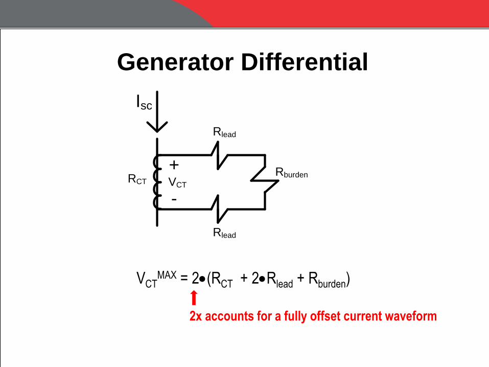
Generator Differential
Rlead
Rlead
RburdenRCT VCT
+
-
Isc
VCTMAX = 2(RCT + 2Rlead + Rburden)
2x accounts for a fully offset current waveform
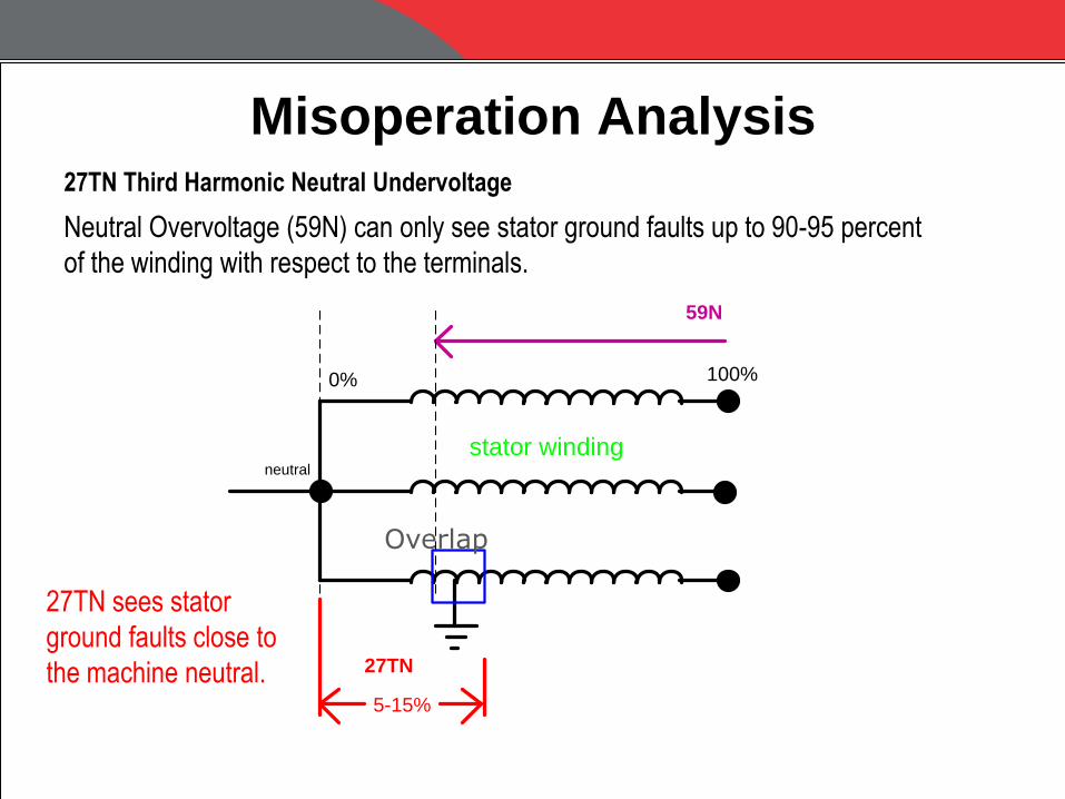
Misoperation Analysis
27TN sees stator
ground faults close to
the machine neutral.
neutral
5-15%
stator winding
0% 100%
27TN
59N
Overlap
Neutral Overvoltage (59N) can only see stator ground faults up to 90-95 percent
of the winding with respect to the terminals.
27TN Third Harmonic Neutral Undervoltage

27TN Third Harmonic Neutral Undervoltage
If the voltage magnitude drops below the pickup, then a trip occurs after time delay.
VN
3V0
Pickup
Trip
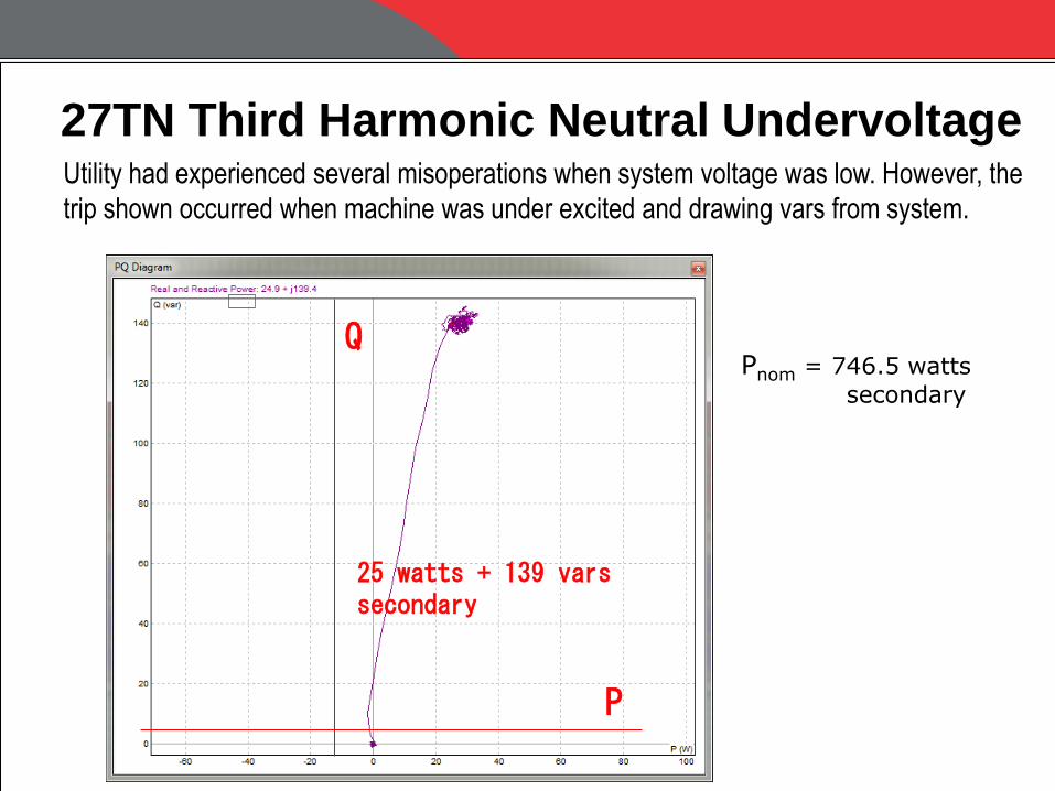
27TN Third Harmonic Neutral Undervoltage Utility had experienced several misoperations when system voltage was low. However, the
trip shown occurred when machine was under excited and drawing vars from system.
P
Q
25 watts + 139 vars secondary
Pnom = 746.5 watts
secondary

27TN Third Harmonic Neutral Undervoltage
Third harmonic neutral voltage changes as a function of load.
Pickup setting is typically set equal to one-half of minimum value measured
during normal operation.
VNmin = 1 volt
Input 1 = 52b
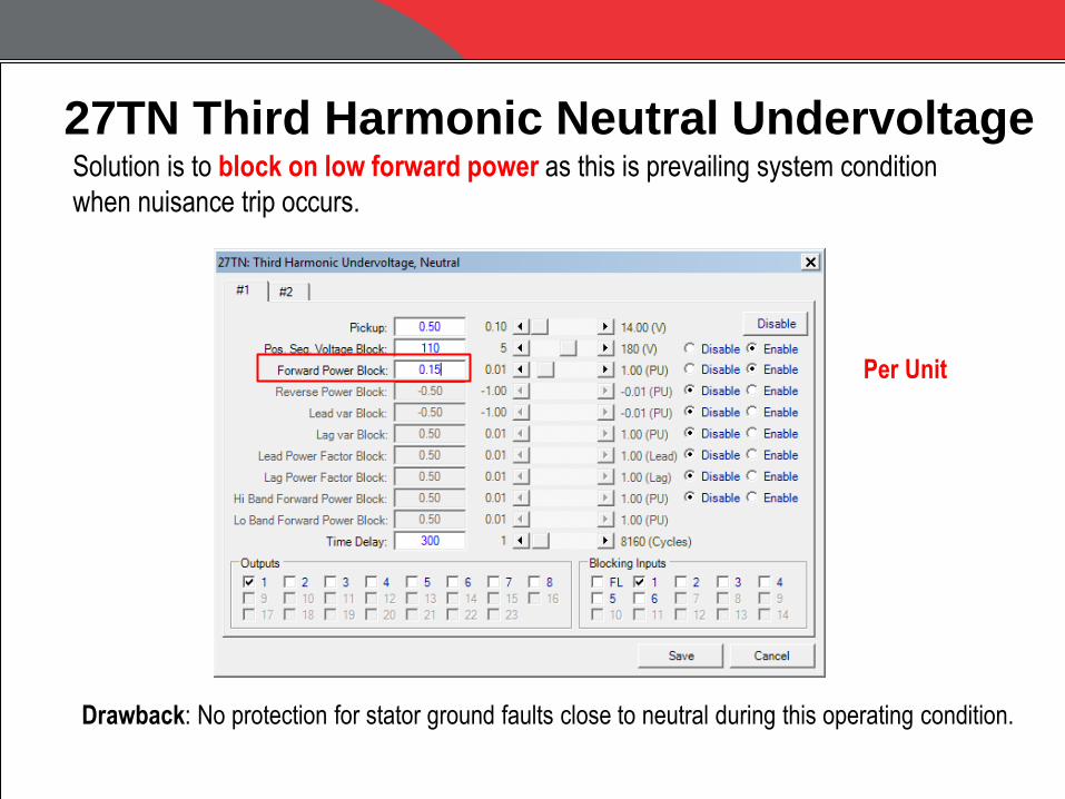
27TN Third Harmonic Neutral Undervoltage Solution is to block on low forward power as this is prevailing system condition
when nuisance trip occurs.
Drawback: No protection for stator ground faults close to neutral during this operating condition.
Per Unit

27TN Third Harmonic Neutral Undervoltage Customer is strongly considering installation of 100 percent stator ground fault
protection using sub-harmonic voltage injection (64S).
RN
1B1
1A1
1B4
1A3 1A4
20 Hz
Band Pass
Filter
20 Hz
Generator
4A1
1A1
1A2
1A3
2A3
2A1
3A2
3A14A3
Bl
3A3
Supply
Voltage
DC
+VAux
-VAux
44 45
52 53
L K
l k
V N
I N
Neutral
Grounding
Transformer
Wiring
Shielded
20 Hz CT
59N
HighVoltage
Low
Voltage
64S Relay
27TN Third Harmonic Neutral Undervoltage
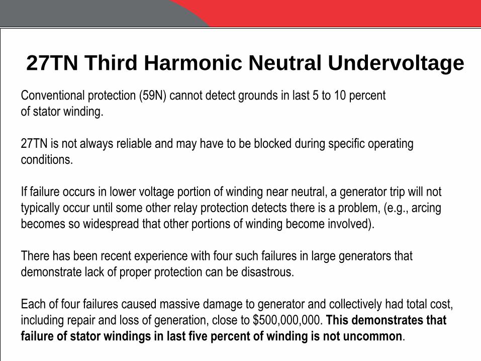
Conventional protection (59N) cannot detect grounds in last 5 to 10 percent
of stator winding.
27TN is not always reliable and may have to be blocked during specific operating
conditions.
If failure occurs in lower voltage portion of winding near neutral, a generator trip will not
typically occur until some other relay protection detects there is a problem, (e.g., arcing
becomes so widespread that other portions of winding become involved).
There has been recent experience with four such failures in large generators that
demonstrate lack of proper protection can be disastrous.
Each of four failures caused massive damage to generator and collectively had total cost,
including repair and loss of generation, close to $500,000,000. This demonstrates that
failure of stator windings in last five percent of winding is not uncommon.

27TN Third Harmonic Neutral Undervoltage
Catastrophic Damage - Stator Grounds in last 5% of Winding
Winding Damage: Broken Stator Winding Conductor
Core and Winding Damage: Burned Open Bar in a Slot
Burned Away Copper: Fractured Connection Ring
27TN Third Harmonic Neutral Undervoltage
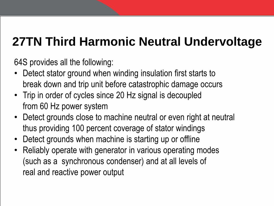
64S provides all the following:
• Detect stator ground when winding insulation first starts to
break down and trip unit before catastrophic damage occurs
• Trip in order of cycles since 20 Hz signal is decoupled
from 60 Hz power system
• Detect grounds close to machine neutral or even right at neutral
thus providing 100 percent coverage of stator windings
• Detect grounds when machine is starting up or offline
• Reliably operate with generator in various operating modes
(such as a synchronous condenser) and at all levels of
real and reactive power output

27TN Third Harmonic Neutral Undervoltage
64S can be commissioned in less than one hour
assuming there are no wiring errors.
Numerical Generator Relay 20 Hz Metering

Incorrect Phase Rotation Settings
Some power systems have ACB phase rotation.
Generator Protection Numerical protection relays require a setting to determine the correct phase rotation.
ABC Phase Rotation

Incorrect Phase Rotation Settings
R
X 40 Loss-of-Field Protection
• 40 operates on Z1 (positive-sequence impedance).
• 40 measures incorrect impedance due to wrong phase rotation setting
• 40 trips each time customer attempts to synch the generator to the grid
How did this get past commissioning ?
Impedance t ra j e c t o r y
Incorrect Phase Rotation Settings
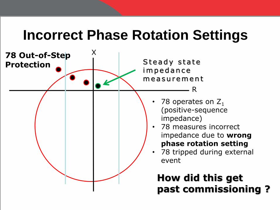
R
X 78 Out-of-Step Protection
• 78 operates on Z1 (positive-sequence impedance)
• 78 measures incorrect impedance due to wrong phase rotation setting
• 78 tripped during external event
How did this get past commissioning ?
S teady s t a t e impedance measu remen t
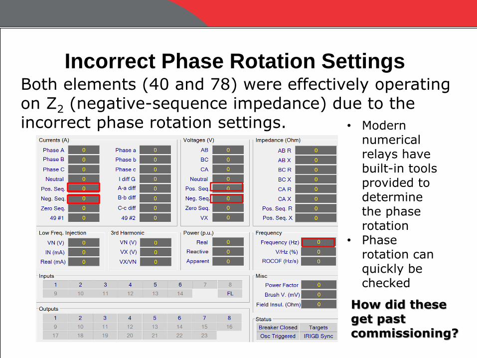
Incorrect Phase Rotation Settings Both elements (40 and 78) were effectively operating on Z2 (negative-sequence impedance) due to the incorrect phase rotation settings. • Modern
numerical relays have built-in tools provided to determine the phase rotation
• Phase rotation can quickly be checked
How did these get past commissioning?
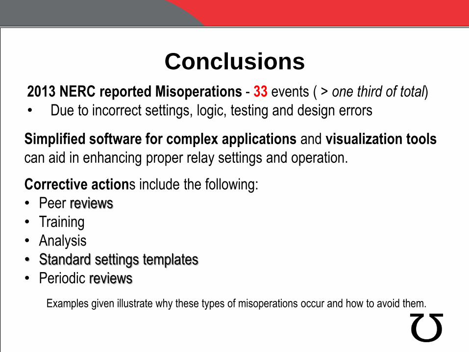
Conclusions 2013 NERC reported Misoperations - 33 events ( > one third of total)
• Due to incorrect settings, logic, testing and design errors
Corrective actions include the following:
• Peer reviews
• Training
• Analysis
• Standard settings templates
• Periodic reviews
Examples given illustrate why these types of misoperations occur and how to avoid them.
Simplified software for complex applications and visualization tools
can aid in enhancing proper relay settings and operation.
Questions ?
Steve Turner Beckwith Electric Company
Improving System Protection
Reliability and Security
Minnesota Power Systems Conference 2015


