Page 1
Department of Mechanical Engineering
Improving the Performance of Solar
Stills using Sun Tracking
Author: Taiwo, M. Olalekan
Supervisor: Prof. Joe Clarke
A thesis submitted in partial fulfilment for the requirement of degree in
Master of Science in Renewable Energy Systems and the Environment
2010
Page 2
2
Copyright Declaration
This thesis is the result of the author’s original research. It has been composed by the
author and has not been previously submitted for examination which has led to the
award of a degree.
The copyright of this thesis belongs to the author under the terms of the United
Kingdom Copyright Acts as qualified by University of Strathclyde Regulation 3.50.
Due acknowledgement must always be made of the use of any material contained in,
or derived from, this thesis.
Signed: Taiwo, M. Olalekan Date: September 2, 2010
Page 3
3
Abstract
Worldwide, some 1.1 billion people lack access to safe water and another 2.6 billion
people lack access to sanitation. For the UN to achieve its Millennium Development
Goals of reducing by half the population without access to water and sanitation by
2015 there is need for concerted efforts in funding research to stern the tide of global
water shortage.
The challenge of providing potable water is quite prevalent in the developing and
poorest countries of the world, especially in the tropics and arid regions. While it
would be quite difficult or challenging to invest in huge/gigantic desalination plants,
they are well endowed with the required energy to drive solar desalination.
Conventional means of providing potable water, especially from fossil fuel, is
becoming increasingly expensive and might be unaffordable by the poorest countries
of the world where water and sanitation is a major challenge. There is a need to find
viable alternative sources of energy.
Various renewable energy sources were explored and the solar energy is adjudged the
best option. With abundance of solar energy in many of the poorest parts of the world
where access to potable water is a challenge; it is reasoned that this is the best and
most viable option.
With solar energy as the source to power our plant; the solar still is the simplest
desalination technology consisting of a shallow basin with a transparent cover and it
is considered because of its cost, simplicity of design, operation and maintenance. It is
equally very compatible for use in the world’s poorest countries and adaptable, for it
does not require complex technical know-how to operate and maintain.
The efficiency of solar energy deployment and performance of a basin-type still is
considered. The effect of sun tracking on the design and operating factors such as the
ambient temperature, basin temperature, brine temperature, cover temperature, and
solar radiation (irradiance/intensity) and how they influence productivity were
Page 4
4
examined and analysed. Basin and brine temperatures have positive effects on the
productivity, but the effect of glass cover temperature was not so obvious. It was
evident from the results that the solar intensity impacted on the productivity directly
and positively. A sun tracking mechanism was explored to determine how this affects
the performance of the still.
The still with the tracking mechanism was found to show some significant
improvement by increasing the distillate yield by 19.6% with an additional 3.8%
increase in overall still efficiency. With the use of a tracking mechanism, the space
required to provide a daily consumption of 2-3 litres of water per person is expected
to be about 1.4m2. This is a significant improvement over the traditional fixed still.
Page 5
5
Acknowledgements
My sincere gratitude goes to Prof. Joe Clarke, my indefatigable supervisor, for his
patience and guidance during the course of this project.
Special mention should be made of Dr. Paul Strachan for his support and advice all
through the MSc programme.
To the numerous authors, whose works were consulted in the build up to this thesis, I
say, thank you for the insight.
I also want to thank all the technicians, colleagues, friends, staff and others too
numerous to mention for their continued kindness and support on this project.
Lastly and more importantly to God, whose will has always prevailed in my life;
Folashade and Oluwapelumi for their endurance, patience and prayers.
Page 6
6
Table of Contents
1 Introduction.............................................................................................................13
2 Literature Review...................................................................................................16
2.1 Energy Sources.…………...................................................……………...18
2.2 Solar Distillation ………………………………………………………...24
2.3 Basin-type Solar Still Design …………………………………………...27
2.4 Heat Transfer Mechanism in a Solar Still ……………………………...29
2.5 Sun Tracking Mechanism………………………………………………..32
3 Method..................................................................................................................35
3.1 Theoretical Analysis................................................................................35
3.2 Design .....................................................................................................36
3.3 Practical Experiment …..........................................................................38
3.4 Sun Tracking ……………..…………………………………………….41
4 Results & Discussion ..........................................................................................43
4.1 Effect of Sun Tracking on the Solar Still…………………………........49
4.1.1 Effect on Construction Material..……………………………….........49
Page 7
7
4.1.2 Effect on Basin and Cover (Glass) Temperature…….............................49
4.2 Effect of Solar Intensity ……...…………………………………………..50
4.3 Still Efficiency…………………….……………………………………...54
4.4 Realisation of the Tracking System……………………………………...55
5 Conclusion & Future Works …….........................................................................60
6 Bibliographies .......................................................................................................64
Appendix….…………………………………….…………...…………….……….68
Page 8
8
List of Figures
Figure 1: Global Distribution of Drinking Water Availability [2].............................13
Figure 2: In search of Water in an arid region [2]......................................................16
Figure 3: A typical basin-type Solar Still [9].............................................................24
Figure 4: Schematic diagram of a basin-type Solar Still [34]....................................25
Figure 5: Basic Concept of Solar Distillation [35]....................................................26
Figure 6: Basin-type Solar Stills with varying Angles of Inclination [18] ...………29
Figure 7: Heat Transfer in a Basin-type Solar Still [21]............................................31
Figure 8: A Schematic diagram of a simple tracking mechanism [24]..……………33
Figure 9: Solar Still and the attached type-K thermocouples....................................39
Figure 10: Tracking in progress …............................................................................40
Figure 11: Digital microprocessors showing Thermocouple Readings ....................41
Figure 12: Effect of Cover (Glass) material on Productivity ………………………43
Figure 13: Temperature Variation of the Brine for both the Fixed Still
and the Tracked Still ...............................................................................45
Figure 14: Temperature Variation of the Basin for both the Fixed Still
and the Tracked Still ...............................................................................47
Page 9
9
Figure 15: Temperature Variation of the Cover (Glass) for both the Fixed Still
and the Tracked Still ..............................................................................50
Figure 16: Temperature Variation of the Fixed Still and the Tracked Still ………51
Figure 17: Temperature Variation for the fixed still ..............................................52
Figure 18: Temperature Variation for the Tracked Still ………………………..52
Figure 19: Solar Intensities for both the fixed Still and the Tracked Still ……..53
Figure 20: Hourly Production for both the fixed still and tracked still ………..55
Figure 21: Schematic diagram of Automated and Manual Tracking Systems…56
Figure 22: Various components of an Automated Sun Tracking System [32]....57
Page 10
10
List of Tables
Table 1: Technical Specifications of the Solar Still ……………................................38
Table 2: Design Features of the Solar Still …….........................................................43
Table 3: Brine Temperature for both the Fixed Still and the Tracked Still ................44
Table 4: Basin Temperature for both the Fixed Still and the Tracked Still ...............45
Table 5: Cover Temperature for both the Fixed Still and the Tracked Still ..............46
Table 6: Ambient Temperature for both the Fixed Still and the Tracked Still……..47
Table 8: Experimental Results and Percentage increase in Total Production...........48
Table 9: Solar Intensities for both the Fixed Still and the Tracked Still...................48
Table 10: The Rise and Set for the Sun for June-Dec., 2010 [33]…………………59
Page 11
11
Nomenclature & Abbreviations
Ae Area of evaporation (m2
)
Ac Area of condensation (m2)
E Water evaporation (and condensation) rate (kg/m2h)
ED ElectroDialysis
hc,I Convective heat transfer coefficient from salt water surface to cover of
still (W/m2K)
hc,o Convective heat transfer coefficient from cover to atmosphere (W/m2K)
hr,I Radiation heat transfer coefficient from salt water surface to cover of
still (W/m2K)
hr,o Radiation heat transfer coefficient from cover to atmosphere (W/m2K)
L Net miscellaneous heat loss rate (W/m2K)
MEB Multi-Effect Boiling
MED Multi-Effect Distillation
MSF Multi-Stage Flash
P Daily production of still (kg/m2
day)
Qsh Net solar energy absorption rate on basin bottom (W/m2
day)
R Amount of incident radiation (W/m2
day)
Page 12
12
RO Reverse Osmosis
ta, Ta Ambient temperature, 0C, K respectively
tb, Tb Basin temperature, 0C, K respectively
tg, Tg Cover temperature, 0C, K respectively
VC Vapour Compression
Wda Mass of dry air circulating per unit time (kg/h)
WH20 Mass of water distilled per unit time (kg/h)
Page 13
13
1 Introduction
Water is essential to life. Next to oxygen, fresh water is the most important substance
for sustaining human life. Access to water is considered to be a basic human right.
However, the increased use and misuse of this resource by the growing population
and increasing industrial activities may lead to a situation whereby countries need to
reconsider their options with respect to the management of its water resources. About
1.2 billion people in the world lack access to potable water, over 2.6 billion without
access to adequate sanitation, and 1.8 million children killed each year by preventable
water-borne diseases [1]; many of these people live within the poorest countries of the
world.
Figure 1: Global distribution of drinking water availability [2]
Water is life, and the threat of unsustainable means of potable water supplies has led
to the reviews of various renewable energy sources to create a cleaner and more
efficient solution for potable water supply. Various modular technologies existed, in
Page 14
14
which potable water can be produced, but these have proved to be quite expensive as
large and very complex designs are involved. Because this problem is prevalent in
the world’s poorest countries, there is need for the technology to be simple in design,
affordable and sustainable.
Conventional solar stills are one method of supplying potable water through using a
renewable and free energy source. The solar still is point-of-use technologies that
have been proven to remove pathogens, heavy metals and reduce salinity. Despite the
fact that this technology can provide a cheap source of potable water they have the
disadvantage that they are on average only 30% efficient and require 2m2
to provide
for one person’s daily needs [3]. The solar stills have often been used in the tropics
where there is abundant supply of solar energy.
In this thesis, a basin-type solar still was designed to investigate the effect of sun
tracking in the performance of conventional solar still using actual environmental
conditions.
Basically, the still consists of a black-lined shallow basin of saline water enclosed by
a transparent cover with sloping sides. Solar radiation passing through the transparent
cover is absorbed by the brine and the black basin liner. This radiation is changed to
heat by absorption, which serves to warm the brine. The warm brine partly evaporates
and humidifies the air above the surface, thereby reducing the density of the air and
causing it to circulate upward.
The moving air comes in contact with inner surface of the relatively cool transparent
cover, and part of the humidity condenses thereon. The liquid condensate forms a film
and flows to the base of the cover, from where it drips into the condensate trough and
is conducted to the outside of the enclosure. The cooled air returns to the surface of
the warm water to repeat the process of humidification. The circulation of air is thus
due entirely to free convection.
Many adaptations have been made to the solar still design to improve the efficiency,
however not so much attention has been paid to sun tracking. This study will
Page 15
15
investigate the use of sun tracking to improve the potable water yield from a
conventional solar still.
The next four sections of this thesis will cover the literature review of solar
desalination systems and more importantly the various renewable systems available
and some research on sun tracking; this will be followed by the method, which is the
storyline of the experiment conducted on the roof top of the James Weir building,
University of Strathclyde, Glasgow involving the design, build and test phases of the
different variables of the still; followed by results and discussion of the data acquired
as well as the analysis of this data; Finally, conclusions will be made and
recommendations regarding future improvements will be proposed.
The purpose of this research was to investigate the effect of sun tracking in the
conventional solar still design. The results were correlated and analysed for
subsequent trends. It was hoped that the sun tracking would improve the overall
potable water yield of the solar still.
Page 16
16
2 Literature Review
The inadequate supply of potable water to meet household needs and the inability to
provide proper sanitation facilities in the world’s poorest countries has become a
major global crisis. This is evident as reported in the United Nation’s Human
Development Report [1], which cites figures of over 1 billion people without access to
clean water, over 2.6 billion without access to adequate sanitation, and 1.8 million
children killed each year by preventable water-borne diseases as a result of lack of
safe water and proper sanitation facilities.
Due to its prime importance, especially from a socio-economic perspective, the
looming water crisis as emphasised in this report reflected on the growing
international recognition of the importance of this crisis. This is important because
forecasts of future water accessibility, demand and availability have already indicated
that greater pressures are likely to be placed on potable water supplies as all regions
of the world continue to develop, especially with the rural-urban drift and urban
sprawls.
Figure 2: In search of water in an arid region [2]
Page 17
17
Due to the pressures placed on water, it can longer be seen as an infinitely renewable
resource that was once thought it was. As a matter of fact, the shortage of water
threatens to make water an endangered natural resource. As it stands, it is potentially a
more critical and vital resource than energy. A water crisis, in contrast to an energy
crisis, is life threatening and if not quickly and properly handled could bring about
grave consequences. Water has no viable substitute, and its depletion both in quantity
and quality has even very great socio-economic implications. Moreover, there are
available means of providing potable water technically and economically.
Water desalination is usually the last resort to overcome the issue of water shortages,
which in the case of seawater is principally an unlimited source. Producing potable
water from seawater through desalination may be quite expensive, but as it is
continually being deployed at different places and the result of thorough studies of
available options with adaptations and improvement both in addressing demand
management and existing resource technology the cost is more likely to come down
and be more readily affordable for all. This global water crisis can be resolved by
using non-conventional approaches and resources, that is, by using treated wastewater
and distillation.
Water Desalination through Distillation
There are different methods and approaches to desalination depending on application,
use and resource. For very huge industrial desalination technologies using either
phase change or semi-permeable membranes to separate impurities; desalination
methods can be categorised into phase change (or thermal process) and membrane (or
single phase process) [4].
The aforementioned processes require some form of chemical pre-treatment of
undiluted seawater in order to avoid corrosion, foaming, scaling, growth of algae,
fungi and fouling. It equally requires some form of post chemical treatment. However,
it is more convenient and useful to classify these desalination processes by separating
them into the change of phase and the separation type without change of phase, the
membrane type.
Page 18
18
A brief mention should be made of the phase change processes. They are: Multi-Stage
Flash (MSF) (a distillation process); Multi-Effect Boiling (MEB) or Multi-Effect
Distillation (MED) (distillation processes); Vapour Compression (VC); Thermal and
Mechanical (a distillation process); Solar Distillation (a distillation process); Freezing.
While the Reverse Osmosis (RO) (a membrane process) and the Electrodialysis (ED)
(a membrane process) [4] are in a single phase category, the membrane process.
2.1 Energy Sources
Different desalination processes require energy in different forms, notably electro-
mechanical or thermal. The effectiveness and viability of a desalination process is
largely due to the quality and availability of energy. It is also dependent on energy
costs.
This account for the high cost of water for water derived from huge desalination
plants running solely on fossil fuel. It makes water from such plants to be
unaffordable, especially for people from small rural communities. Due to the
aforementioned reason, desalination processes are often compared on their energy
consumption and source. As clearly stated above, the quality of the energy is very
important.
High grade energy, such as electricity is seen to be much more valuable than the same
quantity of energy in the form of low grade thermal energy. When selecting a
desalination process, a lot of factors are usually considered. The budget for the
process, options for water purification, sources of energy available and of course, to
whom the project is for (end-users) and at what cost. Obviously for small rural
communities, it would be foolhardy to recommend a huge desalination plant.
Therefore, it is important to note that mere comparison of technologies or schemes
based on their energy consumption alone is not the absolute criteria for selecting a
desalination process [5]. Energy for the desalination system can come from a variety
of sources. The conventional sources of energy are: Diesel generators, Grid
Page 19
19
Electricity, and Waste Heat. The renewable energy sources are: Biomass, Geothermal,
Hydro, Solar, Wave and Wind.
Diesel Generators
Diesel generators usually can provide a continuous and uninterrupted supply of
electricity provided it is being fuelled and maintained as at when due. It is therefore
true that, a desalination plant coupled to a diesel generator is as good as being coupled
to a grid supply because of its firm and continuous power. Generators are usually
considered as a ‘perfect’ source of energy for the desalination plant because of its
consistency and predictability. Since electricity is the usual and major output,
desalination plants using electricity are appropriate and they are the ED, RO or VC.
Diesel generators normally run with an efficiency of about 35%. The remaining
energy is dissipated in the exhaust and in jacket cooling water [6]. For large generator,
the waste heat might be used to run thermal processes such as, MSF and MEB.
It is also possible to use diesel generators for hybrid systems, where the diesel
generators are used in combination with other renewable energy powered systems;
such that, the period of fluctuation of renewable energy supplies can be augmented by
the generator supplies.
The hybrid system is designed in such way that the generator can cut in and out in
order to match demand and supply. In a rural setting, diesel generator is not likely to
be an option as the cost of transporting fuel would be so high to afford and the
technical know-how for the hybrid system, thereby compromising its use.
Grid Electricity
Grid electricity is regarded as a high grade fuel in terms of quality and consistency of
supply. It is generated by burning hydrocarbons and depending on the raw material
used the conversion efficiency is usually about 35%. For certain reasons, it is cheaper
Page 20
20
than electricity derived from renewable energy sources even though there might be
times when this does not apply.
Grid electricity is widely used in huge desalination plants based on electro-
mechanical energy requirements of the following plants; ED, RO and VC. This is due
to the fact that, it is relatively cheap and readily available.
Waste Heat
Waste heat is usually referred to as low grade heat due to its conversion rate and
ability. Waste heat is usually in form of a ‘useful waste’ from a power plant. This is
the rejected heat from a steam turbine. While the thermal plant provides power to the
community, the rejected heat in the form of low pressure steam extracted from the
turbine supplies heat to the desalination system usually large desalination units such
as, the MSF or MED. This could also be harnessed and used to heat a simple solar
still.
Renewable Energy Sources
It is needful that the use of renewable energy be encouraged for desalination systems.
Although renewable energy is not a firm source of power due to variations in supply
and energy is expensive to store in large quantities, there is still a need for it to be
encouraged. It should be encouraged because it is a clean source of energy,
environmental friendly nature and of course, it is naturally occurring. Water is
naturally occurring as well - hence there is compatibility between renewable energy
and desalination.
The major challenge in the deployment of the renewable energy source to desalination
systems is the fluctuation and intermittency of the supply of power and the
availability in terms of time and quantity. This challenge is applicable to wind, solar
and wave energy, but not to geothermal and biomass which can be said to be readily
available and predictable [7].
Page 21
21
Since water can be stored relatively easily, the inconsistency in production of water is
not a challenge from a water supply point of view. If desalination systems can be run
satisfactorily (technically and economically) with regular periods of shut down
without resulting into downtimes, then renewable energy resources can play a major
role in supplying energy to desalination plants.
Wind is a renewable energy source; wind energy is very widespread, with mean wind
speeds in excess of 5 m/s being quite common. It is not in general a predictable or
dependable energy source, although there are exceptions: thermally-driven winds
around the edges of desert regions will exhibit a daily cycle. Southern California,
which has been densely populated with wind turbines, is a prime example.
It is possible to use the wind energy to supply either electricity or mechanical power.
Though good wind energy is often available on an intermittent basis in arid areas,
particularly islands the affordability of this means poses a challenge for the dwellers
in these areas.
Geothermal energy is another source that can be used as a power input for water
desalination, but this is not suitable for this project.
Biomass is another source of renewable energy. This is not likely to be a popular
option as the availability of biomass suggests that there is adequate water in supply to
grow it (biomass) which then implies that a desalination system is not necessary.
Although there are times and circumstance that could inform the availability of
biomass and yet there is inadequate water supply. In that circumstance, biomass
energy based system could be used. This however, would only produce electrical
power to power huge desalination plants. There is also another issue of supply of the
biomass as this is seasonal.
It is not likely that the biomass would be appropriate in the desert and some arid
locations due to the fact that these areas are not likely to support the growth of
biomass and the cost of getting same would be prohibitively high.
Page 22
22
Battery systems are not a source of renewable energy, but a means of storing energy.
Battery systems are a very expensive means of storing energy as they have limited
storage capacity. Batteries practically are not a good energy source for desalination.
Although it is possible to use them for some hybrid systems, using them alongside
some renewable sources possibly.
In some instances, they can be used as a backup for some specific periods when there
is short supply from the renewable source. They can be used as a stop gap for systems
instrumentation in order to reduce downtime. More often than not, they are used in
small system as a buffer system when the renewable energy plant is down.
The demand for water is increasingly becoming a global challenge. In many parts of
the world local demand is outstripping conventional resources. More economical use
of water, reducing distribution losses and increased use of recycled water can help
alleviate this problem but if there is still a shortfall then desalination of seawater or
brackish water may be an option [4]. From all available energy sources, solar energy
is the one that correlates best with the demand for water, because it is obviously the
main cause of water scarcity.
Solar
Energy from the sun is said to be the solar energy. This is the earth’s primary energy
flow and equally too, the most abundant on the earth crust. There are two major ways
in which the solar energy can be used or harnessed. It can be used either as a thermal
energy by heating a fluid or by converting it into electricity using photovoltaic arrays
(PV). The former would be looked in detail in the design of the solar still. Solar
energy is a relatively diffuse source of energy. It is also available almost everywhere,
unlike geothermal, wave, wind or even conventional fuels.
Depending on the energy demand of the application, it may require large areas. Yet,
most solar energy conversion systems are modular and can be installed almost
everywhere which relieves the space availability problem [4].
Page 23
23
The solar energy can be deployed and use for simple desalination systems especially,
the solar still for production of potable water in the tropics and arid regions of the
world where there is abundance of this natural resource. These regions are well
endowed with this resource and it should be fully exploited.
Solar Thermal
Solar thermal energy is one of the most promising applications of renewable energy to
seawater desalination. A solar distillation system may consist of two separated
devices, the solar collector and the conventional solar still. Indirect solar desalination
systems usually consist of a commercial desalination plant that is connected to
commercial or special solar thermal collectors.
The possibility of capturing energy with the distillation process using a simple solar
still is not only possible, but achievable. However, the still is simple and relatively
cheap, but it is not particularly efficient. That is why over the years, different types of
designs (for example; the baffle type, the wick type, the single slope type, the double
slope type) have been developed to improve on the performance of the still and to
increase its efficiency. Moreso, production of higher grade energy in the form of hot
fluids which can be used to drive more thermally efficient desalination processes such
as MSF and MEB have also been deployed.
The deep solar ponds and concentrating parabolic collectors are also good examples
of adaptations and modifications to the simple still [26]. In all of these, the energy
collected is proportional to the area of the collectors and the efficiency of the device.
Solar ponds are by their design and nature quite static, but the energy storage is cheap.
This energy can be connected to a desalination system to generate potable water. Most
of the other collectors can be made to track the sun which in turn improves their
efficiency but might also have some cost implications. The thermal energy storage is
relatively cheap. This is stored in the form of a hot fluid in insulated tanks or in the
case of solar ponds - within the solar pond.
Page 24
24
There are two main methods for the deployment of solar energy in seawater
desalination. The first method uses the ‘greenhouse’ effect to evaporate clean water
from salty water in an enclosed simple solar still. Figure 3 shows a typical basin type
solar still containing the sea water covered with a transparent air tight top. The second
technique which applies the use of solar energy for desalination is somewhat
complicated and often involves more than one subsystem: one for energy collection,
another for energy storage, and a third subsystem for energy usage in the desalination
process. The desalination process may be distillation, electro-dialysis, or reverse
osmosis [8]. The last two are particularly attractive for the desalination of brackish or
low salinity water.
The distillation process is the most developed thus far for seawater.
Figure 3: A typical basin-type solar still [9]
2.2 Solar Distillation
Solar distillation has been used for many years, usually for comparatively small plant
outputs. Over the years, substantial research has been carried out to find out ways into
improving the efficiency of the process. Research work has been carried out in many
parts of the world.
Page 25
25
Solar distillation uses, in common with all distillation processes, the evaporation and
condensation modes, but unlike other processes energy consumption is not a recurrent
cost but is incorporated in the capital cost of the solar collector. The solar still
therefore, is of a simple design, construction and maintenance with ease of operation.
It is best suitable for regions of the world with high solar intensities.
The mechanism of operation is based on the transmitting, absorption and reflective
properties of glass and other transparent materials. The glass has the property of
transmitting incident short-wave solar radiation which passes through the glass, the
glass being a medium of transfer of heat, into the still to heat the brine.
However, the re-radiated wavelengths from the heated water surface are infra-red and
very little of it is transmitted back through the glass as it is shown in Figure 4.
Figure 4: Schematic diagram of a basin-type solar still [34]
Today, producing volumes of pure potable water is not only technically feasible but
equally economically viable using the desalination of seawater. The challenge though
has been to produce potable water for rural communities for drinking and sanitation to
help meet the Millennium Development Goal without compromising standards.
In meeting the challenges of the provision of potable water for drinking and
sanitation, huge desalination plants have been built. The introduction of dual-power
Page 26
26
plants were also deployed to reduce the cost of electricity and water which could
impact negatively on the populace. Exhaust heat from power plants were also
deployed as an alternative for running desalination systems. These are large
desalination systems though. However, not all water demands are coupled with the
need for additional electric power.
Solar energy may be deployed to produce fresh water from the sea. This may be
accomplished in a large system or in a simple basin-type solar desalination unit.
On a practical basis, certain things ought to be taken into consideration while
designing and operating a solar still. For instance, shallow basins require large
expanse of land. This land has to be cleared and levelled in readiness for the
installation of the still; obviously this attracts some additional cost. Oftentimes and
because the water to be treated is salt water, salt crystals build up on the dry part of
the basins. This can reduce the overall absorption area of the basin, thereby impacting
negatively on the effective basin area. Leakage can cause distillate to leak back into
the basin or even leak out of the basin [10]. It is equally necessary to flush the still
basin on a regular basis so as to remove accumulated salts and microbes that might
have grown in the brines. The use of algaecides might also be encouraged to control
the growth of algae.
Figure 5: Basis concept of solar distillation [35]
Page 27
27
2.3 Basin-Type Solar Still Design
Certain factors influence the choice or selection of different Renewable Energy
Sources for any given desalination technology. Since the primary focus is the world’s
poorest countries believed to be in the tropics, the most viable renewable source
would be the solar energy. However, the most important considerations should be the
simplicity of the design, its affordability, sustainability, and maintainability and
operational ability.
The basin-type solar still is an artificial way of replicating the hydrological cycle. The
stills apply the principles of evaporation and condensation that is seen within the
precipitation cycle. Stills can however, be classified into two main categories; active
and passive. Active stills often employ mechanical methods to replenish the water
supply; these stills require more maintenance, skilled labour and an energy input. For
these reasons the active basin solar stills are not regarded as an economical option for
providing potable water, especially in developing countries.
There are a few concepts that are generally applied to the conventional still design.
The glass must be at a minimum of 100
to the horizontal to allow the condensate to
flow effectively into the collecting tube; yet still allow as much solar energy to reach
the water as possible. The angle of the glass should be increased for different latitudes
to obtain the optimum angle. It is also important to note that the positioning of the
solar still in terms of North and South will change with the hemisphere. The basin is
often painted black to absorb a greater amount of radiant heat; the most suitable
application would be a coat of matt black paint to ensure that very little is reflected.
Despite the fact that solar stills are easily constructed and employ principles that have
been known for centuries there are major inefficiencies within the system. The
conventional still suffers from: low water yield due to the combination of
condensation and evaporation in one chamber; microbial contamination when
subjected to long periods of low temperatures; shallow basin stills store small
amounts of sensible heat and it relies on human factors to maintain optimum
Page 28
28
performance. The success of the still relies on the replenishment of water; and
maintenance routines such as the flushing of the basin to remove microbial build-up
and clearing dust particles and dirt from the glass surface. These factors all contribute
to the average efficiency of the still.
There has been extensive research on the adaptations that can be made to the
conventional still design to improve the performance of the system. These
investigations have included structural changes such as baffle plates, reflective back
plates, wick methods; physical methods such as evacuation; use of coupling of a flat-
plate; storage methods by use of dye or sensible heat storage; the performance of a
single slope basin still with some computational model; development of active passive
still with separate condenser; and the use of phase change materials (PCM) [11-16].
These methods are all an attempt to improve the water yield over the 24 hour period;
however the more adaptations that are made the more expensive the still becomes. A
simple, cheap but effective solution must be found.
The biggest contributing factor to the effectiveness of the conventional still is the
temperature difference between the basin and the glass – the larger the temperature
difference the greater the condensation rate. Shallow basin stills are more productive
than deep basin stills overall, however during the night the water cools rapidly as little
sensible heat is stored within the water.
Adaptations such as incorporating a sun tracking system which can be used with
single-axis solar concentrating systems as an enhancer have been attempted to
improve the performance of the still [17]. The key objective of this project therefore,
is to improve the performance of a traditional single slope solar still through the
combined functioning of the solar still with a sun tracking mechanism to increase the
solar still capability to capture more solar radiations which in turn would increase
distillate yield.
Page 29
29
Figure 6: Basin-type Solar Stills having varying Angles of Inclination [18]
2.4 Heat Transfer Mechanisms in a Solar Still
The mechanisms of heat transfer within a solar still are basically dependent on the
climatic effects and the amount of solar radiation that enters the basin. More
importantly and frankly too, the performance of the still depends on how much of the
solar irradiance that reaches the water in the basin of the solar still.
When the sun’s radiation reaches the Earth it is both scattered and absorbed by the
atmosphere. The radiation that then travels through the Earth’s atmosphere is known
as “sky” radiation, this is the radiation incident on the Earth’s surface after the initial
waves from the sun have been absorbed and scattered by the atmosphere [19]. The
“sky” radiation that travels to the Earth’s surface can then be used as a valuable
energy source for desalination.
The direct and diffuse radiation enters the still through the glass cover after partially
being reflected and absorbed by the glass itself. Once in the evaporating chamber the
radiation is further transmitted, reflected and absorbed by the water until it reaches the
blackened basin where most of it is fully absorbed. The basin then begins to heat up
and in turn through convective processes heats the water causing it to evaporate.
Page 30
30
Due to the fact that the glass cover remains at a temperature lower than the dew point
temperature (the temperature at which water saturates) the vapour begins to condense
on the inside of the glass surface through the mechanism of drop-wise condensation.
This is where the vapour condenses in discrete droplets and grows by means of some
form of accumulation until it becomes large enough to move under gravity down the
glass and can be collected in a pipe at the lower end of the still. This method of
condensation has a heat transfer rate of 10 times that of film condensation which
allows the heat to be dissipated at a faster rate [20]. This allows the excess heat
absorbed by the glass to be dissipated and is lost to the atmosphere.
A simple representation of the heat transfer mechanisms within a still can be seen in
Figure 7. Often the formation of drop-wise condensation can reduce the amount of
radiation entering the still, and can contribute to a reduction in distillate production in
the latter part of the day.
The heat received by the film of condensed water, by radiation from the brine surface,
by convection from air-vapour, and by conduction of vapour is conducted through the
water film and glass to the external surface of the cover. The small amount of solar
energy absorbed in the cover is also conducted outward. The heat which the cover
(glass) has received is then transferred from the outer surface to the atmosphere by
convection and radiation.
The heat transfer processes in the solar still are all dependent on the difference in
temperature between the brine surface and the glass. The higher the difference, the
greater is the energy transfer rate by each mechanism. Furthermore, the higher the
brine temperature, the greater the proportion of energy usefully transferred by
evaporation.
Page 31
31
Figure 7: Heat transfer in a Basin-type Solar Still [21]
The solar energy transmitted by the glass is partly absorbed in the brine, with the
majority of it being absorbed on the basin base. Heat is conducted from the basin base
surface into the brine, thereby increasing its temperature and vapour pressure; partial
vaporisation then occurs. The warm vapour saturated air is carried by the convection
currents to the transparent glass cover, which is generally cooler than the brine.
Moisture condenses on the underneath of the glass, the heat of condensation being
conducted through the glass cover to the surrounding atmosphere; the partly
dehumidified air drifts back to the surface of the brine for further moisture addition. A
thin film of condensate flows down the transparent glass cover to the collecting
trough, from which it passes to storage.
The incoming solar radiation, usually composed of direct radiation from the sun and
diffuse radiation from the clouds and sky, is partly reflected by the outer and inner
cover surfaces, very slightly absorbed in the cover, slightly reflected by the brine and
the base of the basin; the balance is absorbed by the brine and the bottom of the basin.
Another small portion of energy is lost by conduction through the bottom into the
ground or through insulation under the base from the energy absorbed by the basin
bottom.
Page 32
32
The brine is warmed by the convection currents in the shallow basin to the air-water
interface, where transfer of mass and energy takes place. Since the vapour pressure of
the surface water is greater than the partial pressure in the air space, evaporation into
the overlying air film occurs [22]. This transfer of water is accompanied by sensible-
heat transfer from the warm brine into the air-vapour mixture in contact with it. Both
processes produced a temperature rise and density decreased in the air-vapour
mixture, causing it to rise toward the transparent glass cover.
Supplementary to the convective heat transfer from brine surface, is a transfer of heat
to the cover by radiation. The glass cover is cooler than the brine partly due to the
breeze from the outerside and partly due to the condensate on the inner underside, so
the radiant transfer process is essentially between two water surfaces, net radiation
being from the brine in the direction of the glass cover. Since the glass cover is cooler
than the air-vapour mixture coming in contact with it, the difference in vapour
pressure causes diffusion of water vapour through the air film to the water layer on
the underside of the cover. Condensation occurs due to the latent heat being released
from the water film.
2.5 Sun Tracking Mechanisms
Sun tracking, simply put, is the process whereby the solar radiation of the sun is
sensed and being followed from sunrise to sunset. This can be achieved in two ways;
manually and by means of an automated device.
The reason for sun tracking is not far-fetched. Since the basin-type solar still requires
much of the solar irradiance to be transmitted into the still basin to heat the brine for
evaporation and condensation to take place. It is therefore, evident that the more solar
intensity, the faster the evaporation and the higher the condensate which would
eventually give rise to a higher distillate yield.
The Sun moves relative to the Earth’s surface at the rate of 15° per hour east to west
and by approximately 46° per annum north to south. This means that fixed solar stills
will hardly ever by perfectly aligned with the Sun [23]. At latitude 55° north, a south-
Page 33
33
facing solar still angled at 10° will only be perfectly aligned at midday on mid-
summers day. Solar stills having tracking systems will be perfectly aligned with the
sun all the time it is shining. The fixed solar still system will only be aligned to the
sun at about midday and only a fraction of the glass cover is being presented for the
rest of the day.
A Sun Tracking mechanism is a device incorporated into a solar still which follows
the movement of the sun across the sky with the aim of ensuring that maximum solar
irradiance is transmitted through the glass cover of the still into the basin and is
absorbed by the brine from sunrise to sunset, throughout the day.
The sun tracking mechanism is grouped into two types, the single axis and the double
axis models. The single axis is usually on a horizontal axle or vertical axle depending
on the region of use and application. The horizontal is used in the tropics where the
sun is very high at midday, but with shorter days while the vertical is used in high
latitudes where the sun is slightly high, but with very long summer days. The double
axis sun tracking mechanism has both a horizontal and vertical axle so, can be
deployed anywhere in the world [24].
Figure 8: A schematic diagram of a simple sun tracking mechanism [24]
Page 34
34
In the last century, Pasteur used a concentrator to focus sun rays onto a copper boiler
containing water. The steam thus generated from the boiler was then connected to a
conventional water-cooled condenser where the distillate was collected [4].
Before now, some researchers have used sun tracking systems to investigate
performance enhancement for distillate yield in the solar still or for power production
in photovoltaics arrays (PV) [25]. The experimental investigation of a collector with
six parabolic troughs using sun tracking systems [26] was also considered.
The primary aim of using sun tracking system was to investigate how it improves the
performance, either in the solar still or in any other systems for which it was
deployed. The purpose of this research is to investigate the effect of sun tracking in
the conventional solar still design.
Page 35
35
3 Method
3.1 Theoretical Analysis
Supplying the heat for evaporating the condensate and removing heat from the
condensate are basic requirements for energy transfer in a solar still [27]. These two
heat rates are quite importantly equal at about 577.8 kJ/kg of distilled water. The
efficiency of energy usage in the solar still would depend on the percentage of total
incident solar radiation available for the distillation process.
The assumptions stated in the equations below have been carefully studied and
properly analysed. They have been found to be consistent and have a direct bearing on
this project.
Suppose the absorption of solar intensity by the glass and temperature drop through
the glass is negligible, the heat balance on the glass per unit area is:
(hc,o +hr,o)(tg-ta) = (hc,i+hr,i)(tb-tg) + Eλ (1)
Suppose also, the glass area is equal to the basin area, the overall energy balance of
the still can be represented as follows:
Qsh/24 = (hc,o +hr,o)(tg-ta) + E(tb-tg) + L (2)
According to Löf [28], the individual terms in equations (1) and (2) can be
represented as follows:
Convective heat transfer (glass to air) = 1.514(tg-ta) (3)
Thermal radiation (glass to air) = 0.461 x 10⁻⁸
(T4
g-T4
a) (4)
Convective heat transfer (basin to glass) = 0.145(tb-tg)1.25
(5)
Page 36
36
Thermal radiation (basin to glass) = 0.444 x 10⁻⁸
(T4
b-T4g) (6)
Heat of condensation (basin to glass) = 0336(tb-tg)0.25
(WH2O/Wda)λ (7)
Substituting the above into equations (1) and (2), then the heat balance on the glass
per unit area is:
1.514(tg-ta) + 0.461 x 10⁻⁸
(T4g-T
4a) = 0.145(tb-tg)
1.25 + 0.444 x 10
-8(T
4b-T
4g)
+ 0336(tb-tg)0.25
(WH2O/Wda)λ (8)
Suppose there is a heat of conduction losses of about 13.56 W/m2
[27], the
relationship for the overall energy balance on the still per unit area is:
Qsh/24 = 1.514(tg-ta) + 0.461 x 10⁻⁸
(T4
g-T4
a) + 0.605(tb-tg)1.25
(WH2O/Wda) + 13.56/24
(9)
In terms of daily performance, the overall efficiency of the solar still can be expressed
as:
Still Efficiency (%) = (57.78 x 10⁶P)/R
3.2 Design
This project took into cognisance the fact that the structure to be used should possess
a number of features intended to guarantee an efficient and effective evaluation of the
results.
The design is a basin-type solar still (horizontal water-filled basin), covered by a
sloping surface transparent to solar radiation, on which water is condensed and
collected. Salt water was supplied to the basin with a depth of 110mm. The bottom of
the still has a black surface to absorb solar energy. A transparent glass cover is placed
on top of the basin such that its surface slopes down into a small trough at its lower
edge. The trough is connected to a flexible hose for collection of the distillate.
Page 37
37
The still was designed with an optimum basin aspect ratio of 2 [29], where the length
is twice the width, to ensure that the maximum amount of solar radiation reflected by
the walls was absorbed by the water. The basin was constructed with stainless steel
(2mm thickness) and painted black to absorb the radiant heat. It was then secured
inside an insulated casing of expanded polystyrene (50mm thickness) and plywood
(3.6mm thickness). A semi-circular PVC pipe was attached at the lower end of the
box to collect the distillate and directed it out to be collected. A glass panel (4mm
thickness) was then placed on top of the still at an angle of 100 to the horizontal to
ensure that the minimum amount of condensate dripped back into the basin [30].
The still was then constructed in the workshop. After construction the basin edges
were sealed with waterproof sealant and the basin liner was painted black. The basin
of the solar still is made water-tight to avoid water leakage and the inside surface is
blackened to absorb maximum solar radiation.
The bottom and sides of the basin are insulated to reduce the heat losses to the
surrounding. There were also some minor modifications made to the outlet pipe to
ensure that there was no seepage and to decrease humidity. Once all of the
modifications were made the solar still was set-up on the roof top of the James Weir
building for testing.
There are many adaptations and variations that could be made to this design; however
the main focus was to investigate whether sun tracking would increase the efficiency
of the desalination process. As a result the other modifications were not considered in
great detail.
Page 38
38
Table 1: Technical specifications of the solar still
3.3 Practical Experiment
The experimental work was carried out on the roof top of the James Weir building,
using actual environmental conditions. The experiment was carried out at the peak of
summer between July and August, 2010. Due to the intermittency in weather
variations; measurements, testing and readings were taken every 15 minutes to ensure
accuracy.
The temperature fluctuation of the brine and the glass was monitored using a number
of temperature sensors, type-K thermocouples. The type-K thermocouples were used
for accuracy and because of its resilience in water. Each of the type-K thermocouples
(with a range of 0-1000C) was first tested to ensure that the voltage output increased
with increasing temperature. The thermocouples were stripped, welded, and tested for
adequate voltage variations on temperature changes and then secured in the basin.
Once working the thermocouples were soldered, covered with heat shrink wire and
protected with a waterproof sealant. Six of the temperature sensors were placed on the
glass and six in the brine. Two were placed in between the basin and the insulation;
another five were placed on the basin. The sensors were then connected to a digital
Width 0.45m
Length 0.90m
Glass area 0.478m2
Base area 0.405m2
Glass thickness 4mm
Glass slope
100
Page 39
39
microprocessor (The accuracy of this device is in the range of +0.10C for the
temperature measurements between 0 and 1000C) and then calibrated to read the
temperature measurements to allow the temperatures to be recorded every 15 minutes
throughout testing. To ensure that the temperature of the glass was measured correctly
and not affected by the ambient environment insulating and aluminium tape were
applied to cover the sensor.
Figure 9: Showing the still and the attached type-K thermocouples
The solar intensity was measured using a pyranometer, which measures the
instantaneous intensity of the radiation in (W/m2); having a range from 0 to 1500
W/m2. The twenty type-K thermocouples were coupled to a digital microprocessor
(thermometer with a range of 0 to 1000C with ±0.1
0C accuracy) and were used to
measure the temperatures of the various compartments of the still system.
Page 40
40
Figure 10: Showing tracking in progress
The testing was carried out over a continuous period to simulate the performance of
the still over a prolonged time. It was decided to conduct the experiment in this way
because it is known that the performance of the still decreases over time due to the
increased temperature of the glass. The condensate was measured at sunset. The still
was then left to collect its night-time distillate and the new level of water was
weighed each morning at sunrise before the experiment was repeated. The full
experimental set-up can be seen in Figure 9. The still was positioned facing south to
allow for direct solar radiation and allowed the conditions to simulate the most direct
period of sunlight hours (sunrise to sunset) in the day. A number of assumptions were
made to allow the models to be compared and conclusions to be drawn. It was
Page 41
41
assumed that: no condensate or evaporate escaped from the still; the still was
completely airtight; there was no obstruction caused by the temperature sensor wiring
in the practical experimentation; and there were no losses of the condensate to the
atmosphere or retention in the collection pipe.
Figure 11: Digital microprocessors showing thermocouple readings
3.4 Sun Tracking
To capture the maximum solar intensity for irradiance during the day by the solar still,
there is a need for the solar radiation, direct and diffuse to be tracked for optimum
performance. The essence of sun tracking is to ensure that the effective solar
irradiance is achieved from sunrise to sunset. This can be carried out in two ways,
either by incorporating an automated tracking device/system in the still or it could be
done manually.
The latter was preferred as this design is meant to be as simple and as easy to operate
as possible without any such encumbrances associated with huge/gigantic solar
desalination plants.
This is the method deployed in this project. The solar still was tracked from sunrise to
sunset in order to follow the movement of the sun so as to track as much solar
radiation as possible from the sun.
Page 42
42
For the purpose of this project, the sun tracking is done in a 2-dimensional direction.
The beauty of the design however, is that the still is perpendicular to the solar
radiation when tracked especially during the mid-afternoon when the intensity is
supposedly high. So, the solar irradiance is appreciably high.
Page 43
43
4 Results and Discussions
Results of the experiments are presented in the form of graphs and tables, to show the
effect of using sun tracking on different solar still systems (a fixed still and a tracked
still) on the still output, and to highlight the effect of using tracking mechanism on the
received solar intensity, basin, brine temperatures, glass temperature, and the distillate
yield with respect to time, h.
Table 2: Design features of the Solar Still
Cover
material
Shape
cover
Area of (Ae)
evaporation (m2)
Area of (Ac)
condensation (m2)
Ac/Ae
Glass Flatly
inclined
0.405 0.478 1.18
Figure 12: Effect of Cover (Glass) material on Productivity
Page 44
44
It can be seen from Figure 12 that the tracking system has increased the glass cover
temperature due to the increase of the temperature of the vapour inside the still, and
this is due to the high concentration of solar irradiance that passed through the
transparent cover to the black evaporating basin.
Table 3: Brine Temperature for both Fixed Still and Tracked Still
Local time Brine Temperature (0C)
Fixed Still Tracked Still
8 - 25
9 23 28
10 32 39
11 37 44
12 54 63
13 59 65
14 62 64
15 60 62
16 55 59
17 51 60
18 48 53
19 38 48
20 29 41
Page 45
45
Table 4: Basin Temperature for both Fixed Still and Still with Tracking
Local time Basin Temperature (0C)
Fixed Still Tracked Still
8 25 28
9 29 32
10 35 41
11 44 47
12 51 56
13 48 64
14 45 55
15 38 52
16 35 47
17 35 44
18 30 41
19 29 36
20 26 31
Figure 13: Temperature Variation of the Brine for both the fixed still and the tracked
still
Page 46
46
The Figure 13 shows the effects of solar intensity on brine temperature for the two
different systems, the fixed still and the tracked still. It can be seen that the brine
temperature increases for both systems as the solar intensity increases till noon, then
decreases as the solar intensity decreases. It was discovered that the brine temperature
for the tracked still is higher than the fixed still due to the increase of the radiation
concentrations on the absorption capacity of the basin, especially in the morning
hours, which invariably decreases the heat capacity.
Table 5: Cover (Glass) Temperature for both Fixed Still and Tracked Still
Local time Cover Temperature (0C)
Fixed Still Tracked Still
8 23 27
9 25 35
10 30 39
11 33 41
12 34 40
13 36 40
14 35 39
15 33 36
16 31 32
17 29 30
18 27 30
19 24 28
20 23 26
Page 47
47
Table 6: Ambient Temperature for both Fixed Still and Tracked Still
Local time Ambient Temperature (0C)
Fixed Still Tracked Still
8 25 28
9 31 36
10 34 37
11 30 33
12 36 39
13 38 44
14 41 42
15 39 40
16 38 39
17 36 38
18 31 34
19 28 30
20 27 29
Figure 14: Temperature Variation of the Basin for both the fixed still and the tracked
still
Page 48
48
Table 8: Experimental Results and Percentage increase in Total Production
Parameters Fixed Still Tracked Still
Daily Production (g) 290 380
Total Production (g) 370 460
Estimated efficiency (%)* 16.2 20.1
Percentage increase in Total
Production 19.6
* Based on an average solar intensity of 550W/m2 day and an average evaporation area of 0.405m
2
Figure 15 shows the increases in the temperature of the cover (glass) as the solar
radiation incident on glass increases. But the temperatures are lower than the brine
temperature as shown in Figure 13, due to the effect of air cooling on glass. There is
basically energy transfer from the brine to the glass cover by the water vapour
evaporating from the brine surface and then loosing its heat of vaporisation to the
glass cover, which in turn cools off.
Table 9: Solar Intensities (W/m2) for both Fixed Still and Tracked Still
Local time Solar Intensities (W/m2)
Fixed Still Tracked Still
8 160 360
9 400 540
10 700 780
11 620 830
12 830 920
13 910 960
14 780 840
15 640 760
16 410 580
17 250 350
18 160 190
19 50 80
20 0 0
Page 49
49
4.1 Effects of Sun Tracking on the Still
4.1.1 Effect on Construction Material
Due to the material of the construction of the condensation surface, which was glass,
productivity was high from sunrise to sunset (as shown in Figure 12). However, in
Figure 20, this soon disappeared after sunset, as productivity began to decline due to
decrease in solar intensity. The basin also impacted positively on the productivity as
its black colour was able to absorb, emit and transmit much heat into the brine, which
in turn was able to release much condensate to the glass underside.
4.1.2 Effect on Basin and Cover (Glass) Temperature
Tables 4 and 5 give the results of basin and cover temperatures and its plot is given in
Figures 14 and 15. Figure 14 gives the hourly values for the basin temperatures for the
fixed and the tracked stills. That for the tracked still was higher than that of the fixed
still. This is due to the fact that the tracked still is always following the sun radiation
and is often perpendicular to it, while the fixed still is stationary. The results in these
tables and the subsequent figures indicated that a higher basin temperature is
associated with a high productivity.
Page 50
50
Figure 15: Temperature Variation of the Cover (Glass) for both the fixed still and the
tracked still
The experimental results together with the ambient temperature are plotted in Figures
15 and 16. In Figure 20, the hourly values of the productivity are plotted against local
time and in Figure 19; the solar intensity is plotted against time. Figure 20 shows that
the productivity increases until it reaches the maximum in the afternoon then
decreases in the late afternoon. The decrease is due to a corresponding decrease in
solar intensity in the late afternoon (about the same period). This impacted both on
temperatures and distillate production.
4.2 Effect of Solar Intensity
Figure 16 gives the ambient temperature and Figure 19 gives the corresponding solar
intensity. It is clear from these figures that a higher solar intensity corresponds firstly
to a high still productivity and secondly to a high ambient temperature. Thus, the
intensity of solar radiation has the prime importance on the still productivity. Figure
15 clarifies that at sunset, the productivity of the still decreases suddenly and during
the period of diffuse radiation, a very low productivity is attained and little or no
productivity at all when the solar intensity reaches zero.
Page 51
51
Figure 16: Temperature Variation for both the fixed still and the tracked still
From Figures 13, 14, 15 and 16, it can be seem that an increase in the brine
temperature occurs until it reaches the maximum in the afternoon because the
absorbed solar radiation exceeded the losses to the ambient. From about 14 h, water
temperature decreases due to the losses from the solar still which becomes larger than
the absorbed solar radiation. It can be noted that the basin temperature got closer to
the brine temperature because of the continuous contact between them which lead to
equilibrium in heat dissipated.
Also, Figure 16 shows that vapour temperature is the largest temperature in the solar
still because at this temperature the particles have enough energy to evaporate. As the
glass temperature is much smaller than the vapour temperature, it causes condensation
of vapour on the glass. In the early hours of the morning (8–9 h), the glass
temperature is higher than the brine and vapour temperatures causing small
productivity due to the small energy absorbed by the brine at these times.
Page 52
52
Figure 17: Temperature Variation for the fixed still
Figure 18: Temperature Variation for the tracked still
Page 53
53
A careful analysis of these results showed that both the fixed and tracked stills have
very good hourly productivity for most of the sunshine hours. The period from solar
noon to 15 h is excluded from this rule. This is because; the period corresponds to the
highest cover (glass) temperature, thus a lower condensation effect.
The solar distillation process fluctuates with the solar energy intensity as its
production varies from zero for most of the night to a maximum in the early afternoon
of a sunny day. The hourly production of distillate also varies as seen in Figure 20.
Figure 19: Solar Intensities for both the fixed still and the tracked still
Figure 19 shows the solar intensity and variation with the time of the day. This
represents the increase in the solar intensity in the early morning until it reaches the
maximum at around 12 and 13 h, then decreases in the late afternoon. The solar
intensity has an important effect and a positive consequence on the solar still
(distillate) productivity. As the solar intensity increases, the productivity increases due
Page 54
54
to the increase in heat gain for water vaporisation inside the still. The productivity rate
varies with time as time passes from early morning until late afternoon.
The intensity of solar radiation reaching the earth surface varies from zero during the
night to about 830 W/m2 and 920 W/m
2, on a bright afternoon, for both the fixed and
the tracked stills respectively. It is imperative to note that, the climatic condition and
the hour of the day affects the radiation intensity. It can be seen in Figure 19 that the
solar intensity for the tracked still was higher than that of the fixed still for most of the
time. There were conspicuous differences in solar intensities for both the fixed and
tracked still in the early morning till mid afternoon, while in the late afternoon until
the evening the trend subsisted with a nominal difference from the mid afternoon
intensities of the day. The highest differences were in the morning till mid day with an
average increase of about 38%, while in the evening the average increase is about
17%. This is due to the sun tracking mechanism which makes the solar intensity
striking a horizontal surface greater on the tracked still than on the fixed still because
it is being followed all through. Hence, the sun’s rays were vertical on the surface
most of the time during the day.
4.3 Still Efficiency
Table 8 gives a summary for the experimental test and the percentage increase in total
productivity of both the fixed and tracked stills under consideration. The distillate
collected from the still from sunset to the next day morning was added to the daily
production and the resulting total production was used for the calculation of the
increase in total productivity.
It was observed that the still with the tracking mechanism gave an increase in total
distillate yield of 19.6% and an additional increase in overall estimated efficiency of
3.8%
Page 55
55
Figure 20: Hourly Production for both the fixed still and tracked still
Figure 20 shows that the productivity increases until it reaches the maximum in the
afternoon then decreases in the late afternoon unto the evening. The brine temperature
can be taken as one of the parameters that have a direct effect on the productivity after
the solar intensity.
4.4 Realisation of the Tracking System
Solar radiation capturing is dependent on the angle of incidence of the sun to the solar
still’s surface, and the closely perpendicular it is, the more the irradiance. If the solar
still is mounted on a bench, it is more likely that from sunrise to sunset the sunlight
will have an angle of incidence close to 90°in the morning and the evening; thereby,
the radiation gathering ability of the glass cover is practically zero [31]. As the day
advances to midday, the angle of incidence approaches 0°, resulting in an increase in
solar intensity until when the incident radiation on the solar still is completely
perpendicular, and maximum solar intensity is achieved.
Page 56
56
With the foregoing, there is then a need to keep the angle of incidence as close to 00
as
possible in order to achieve higher solar intensity. This can be done by using the sun
tracking system by rotating the solar still to continuously follow the sun as effectively
as possible.
The tracking system can either be automated or manually operated. The automated, as
seamless as its operation might be, has an additional cost attached to it. It might also
be too sophisticated for the rural communities for which this system is designed. So
the viable option for this system is the manually operated tracking system. This has a
simple design, relatively cheaper, affordable and easy to operate.
The automated sun tracker consists of a stepper motor with gear trains, a stepper
controller and some sensors. The sensors sense the solar radiation and send signals to
the controller while the motor rotates the still in order to follow the solar radiation
from sunrise to sunset as shown in the schematic diagram below.
A: An Automated Tracking System B: A Manual Tracking System
Figure 21: Schematic diagram of Automated and Manual Tracking Systems
Page 57
57
The automated tracking system uses some form of smart controllers, stepper motor
(inside the motors are some gears, some have got brakes) for the rotation of the still.
Stepper motor are robust drives which carry out step by step movement and are
controlled by a positioning controller, such as a programmable controller as shown in
Figure 21. Some have rotation monitoring and holding brakes with planetary gears
extended applications. They require stepper motor controllers with microcomputer-
controlled applications used with discrete power device in a step motor. The
programmable controller can control three independent axes of motion with flexible
setup for storing locations, recalling locations and other functions as required. This is
an ideal controller for microscope, x-y, or x-y-z stage applications.
A: Stepper Motor B: Stepper Motor Controller C: Programmable Motor Controller
Figure 22: Various components of an Automated Sun Tracking System [32]
In the automated tracker, the solar still is connected to a computer controlled
mounting system so as to ensure that the solar still is always gaining the maximum
amount of irradiance. It calculates the angle required by the motor and adjusts the
motor’s current angle. It moves the solar still to achieve optimal solar irradiance.
There are usually two sensors being used in the automated tracking system, the
balance and tracking sensors. While the balance sensor sets the system to a zero point,
the tracking sensor determines the orientation of the solar radiation. The signals fed
back by the sensor form the basis of the controller input.
The manual tracker has got some simple set of gears and levers as seen in Figure 21.
In place of a smart controller is an operator. The operator is given some basic training
and a chart stating the solar azimuth and the altitude for each given period of the year.
Table 10 shows the sun or moon rise/set for Lagos, Nigeria from June to December,
2010. The operator relies on the charts or tables such as this to rotate the solar still
Page 58
58
with the aid of attached levers, according to the available data on the charts or tables,
at different intervals from sunrise to sunset. This was the approached used in this
project.
The principle is basically the same, but while the automated sun tracker is
sophisticated with an inherent additional cost, the manual tracker boasts of a simple
design at a very reduced and reasonable cost and of course pocket-friendly for the
remote communities for which it is deployed; and the end-users would be more than
willing to rotate the still in order to track the solar radiation using the levers. After all,
this is better than travelling some kilometers in search of water. The manual tracker
requires little or no maintenance at all. However the operator is to clean it regularly so
that dirt and other foreign bodies do not hinder its operation.
Page 59
59
Table 10: The Rise and Set for the Sun for June-Dec., 2010 [33]
Location: E003 20, N06 35; LAGOS-NIGERIA
Universal Time June July Aug Sept. Oct. Nov. Dec.
Day Rise Set Rise Set Rise Set Rise Set Rise Set Rise Set Rise Set
h m h m h m h m h m h m h m h m h m h m h m h m h m h m
01 0530 1759 0536 1805 0541 1805 0540 1754 0535 1738 0534 1727 0543 1729
02 0530 1759 0536 1806 0541 1805 0539 1753 0534 1738 0534 1727 0543 1729
03 0530 1759 0536 1806 0541 1805 0539 1753 0534 1737 0534 1727 0543 1729
04 0530 1800 0536 1806 0541 1804 0539 1752 0534 1737 0534 1726 0544 1730
05 0531 1800 0536 1806 0541 1804 0539 1752 0534 1736 0534 1726 0544 1730
06 0531 1800 0537 1806 0541 1804 0539 1751 0534 1736 0534 1726 0545 1730
07 0531 1800 0537 1806 0541 1804 0539 1751 0534 1735 0535 1726 0545 1731
08 0531 1801 0537 1806 0541 1803 0538 1750 0534 1735 0535 1726 0546 1731
09 0531 1801 0537 1806 0541 1803 0538 1750 0534 1734 0535 1726 0546 1732
10 0531 1801 0538 1806 0541 1803 0538 1749 0533 1734 0535 1726 0547 1732
11 0531 1801 0538 1807 0541 1802 0538 1749 0533 1733 0535 1726 0547 1732
12 0532 1802 0538 1807 0541 1802 0538 1748 0533 1733 0536 1726 0548 1733
13 0532 1802 0538 1807 0541 1802 0538 1748 0533 1733 0536 1726 0548 1733
14 0532 1802 0538 1807 0541 1801 0537 1747 0533 1732 0536 1726 0549 1734
15 0532 1802 0539 1807 0541 1801 0537 1747 0533 1732 0537 1726 0549 1734
16 0532 1802 0539 1807 0541 1801 0537 1746 0533 1731 0537 1726 0550 1735
17 0532 1803 0539 1807 0541 1800 0537 1745 0533 1731 0537 1726 0550 1735
18 0533 1803 0539 1807 0541 1800 0537 1745 0533 1731 0537 1726 0551 1736
19 0533 1803 0539 1807 0541 1800 0537 1744 0533 1730 0538 1726 0551 1736
20 0533 1803 0540 1807 0541 1759 0536 1744 0533 1730 0538 1726 0552 1737
21 0533 1804 0540 1807 0541 1759 0536 1743 0533 1730 0538 1727 0552 1737
22 0534 1804 0540 1806 0541 1758 0536 1743 0533 1729 0539 1727 0553 1738
23 0534 1804 0540 1806 0541 1758 0536 1742 0533 1729 0539 1727 0553 1738
24 0534 1804 0540 1806 0541 1758 0536 1742 0533 1729 0540 1727 0554 1739
25 0534 1804 0540 1806 0540 1757 0536 1741 0533 1728 0540 1727 0554 1739
26 0534 1805 0540 1806 0540 1757 0535 1741 0533 1728 0540 1727 0555 1740
27 0535 1805 0540 1806 0540 1756 0535 1740 0533 1728 0541 1728 0555 1740
28 0535 1805 0541 1806 0540 1756 0535 1740 0533 1728 0541 1728 0556 1741
29 0535 1805 0541 1806 0540 1755 0535 1739 0533 1727 0542 1728 0556 1741
30 0535 1805 0541 1805 0540 1755 0535 1739 0533 1727 0542 1728 0557 1742
31 0541 1805 0540 1754 0533 1727 0557 1742
Page 60
60
5 Conclusion and Recommendations
I hesitate to draw sweeping conclusions from the results presented in this thesis.
Experience has shown that the correct conclusions are not always immediately clear
even though the results might seem to suggest the contrary. Some care and
considerable thought need to be devoted to the interpretations of the findings.
The experimental results on the solar stills performance and the consequences of the
design parameters have been presented and discussed. It has been concluded that: A
high basin/brine temperature is often associated with high productivity, and the
reverse is true for cover (glass) temperature. A high solar intensity corresponds to a
higher productivity.
The main drive for this study is to evaluate the effect of sun tracking in the
improvement of solar still performance, usability and maintenance in order to help
alleviate world water poverty.
To further help improve the productivity of the still, the following should be
considered: Insulation under the bottom of a shallow basin still reduces the effect of
heat capacity and allows the still to benefit from higher average operating
temperatures. Higher temperatures result in a greater fraction of the absorbed solar
energy being usefully employed in evaporation of water, with lower fractions being
wasted by sensible heat transfer and radiation.
The solar still is a relatively inexpensive, low-technology system, especially useful in
the rural and remote communities of the developing countries where the need for
small plants is promising. There is equally need for innovation and room for
improvement both technically and economically. If properly harnessed, the solar still
provides a considerable economic advantage over other sea water desalination
systems.
The design and operation of a basin-type solar still has been examined
experimentally. The output between fixed still and tracked still were investigated and
Page 61
61
compared. It was found that the productivity of the sun-tracked still is found to be
19.6% higher than the fixed still. It can be concluded that, the present still design
leads to higher distilled water output due to higher brine temperature.
Introducing the sun tracking mechanism to a fixed solar still has improved the
performance (this is relative to the distillate yield) of the conventional fixed single
slope solar still by 19.6% with an additional increase in overall estimated efficiency of
3.8%. This means that there is a possibility to improve the performance of this
conventional solar still system using sun tracking.
By using the sun tracking mechanism the water temperature increased, and the
thermal capacity of the water decreased causing the evaporation rate to increase,
hence the production increased. The conventional single basin-type solar still is the
simplest and most practical design for an installation and less complexity than the
other types.
Solar distillation may be considered as one of the alternatives for fresh water
production in developing countries where potable water is scarce in both quantity and
quality needed for drinking, sanitation and other purposes. The tracking of solar still
will be able to follow the sun during the day, as this method will increase the
concentration of solar radiation; reduce the thermal capacity of the water in the basin,
and increase the productivity.
From the results obtained, it is inferred that the use of a tracking mechanism makes a
solar still to be predictable and it equally increases its efficiency in terms of distillate
yield and overall performance. Tracking system was also found be of immense
assistance and value, having been used in the past to increase the power output of PV
systems.
For rural and isolated communities without technical facilities, the solar still with its
simplicity is the best means of supplying potable water. Since a solar still with a
tracking mechanism can be predicted, the area of production for a daily consumption
of about 2-3 litres per person can be known. From the results obtained, the area
required would be about 1.4m2.
Page 62
62
As a result of the suitability of solar stills for comparatively small output in sunny
climate, the regions of greatest potential application and utilisation appears to be
outside the UK. In many remote communities and arid regions where only brackish or
water is available, solar stills are viable options. The simplicity of the system, the
absence of skilled-labour requirements for construction and operation, and the
matching of high stills capacity with periods of high water demand and natural fresh
water scarcity make this process particularly suitable for use in the developing
countries.
Despite the fact that the model may work and adaptations can be made to allow the
still to be far more productive, considerations of the recipient community must be
taken into account. In many cases development projects fail because they do not
consider the culture and understanding of the community itself. There is the need to
enlighten and sensitise the end-users so as to appreciate the benefits of the technology
and why they should adapt the current best practices.
The users must also be educated on the maintenance of the solar still, the operation of
the tracking system and the storage methods that must be implemented to ensure that
the water remains safe to drink. A major barrier to the technology would be common
perception; in some communities it is believed that all of the nutrients will be
removed if it has been distilled. However, this can be overcome by some form of
enlightenment and getting community leaders involved.
As this is expected to be used in a remote community, this could serve as a means of
employment as operators would be employed and trained on the operation and
maintenance of the tracking system. Despite the barriers of integrating new
technology into a community, it has been proven that point-of-use technologies hold
huge advantages over point-of-source treatment.
Page 63
63
Future Work
Time and circumstance did not allow for full practical experimentation. To fully
analyse the full potential and improve the productivity of a solar still, a number of
other contributing factors must be considered:
• Method of deploying the principles of a low cost, low-emissivity glass
coating for increasing night-time temperatures;
• The design and use of other materials of construction and analyses for
material of best fit in terms of cost and performance;
• The economic viability of inclusion of an automated sun tracking device
for proper monitoring;
• An in-depth analysis into the most appropriate type of tracking
device/system for this application;
• Critical analysis of condensation area and associated shading is worth
exploring.
Page 64
64
6 Bibliographies
[1] Human Development Report 2006 http://hdr.undp.org/en/report/global/hdr2006
Accessed: May 29, 2010
[2] WHO/UNICEF Joint Monitoring Programme (JMP) for Water Supply and
Sanitation. Available from: www.wssinfo.org/ Accessed: July 28, 2010
[3] Spiegler, K. Salt-Water Purification (1977) 2nd Edition, Plenum Press
[4] Kalogirou, S.A., Seawater Desalination using Renewable Energy Sources, Prog.
Ener. Combust. Sci., 31 (3) (2005) 242–281.
[5] Telkes M., Research for Methods on Solar Distillation, OSW Report No 13, PB.
161388; 1956, pg 66
[6] World Bank Final Report (2004) A Review of Key Issues and Experience in Six
Countries, Seawater and Brackish Water Desalination in the Middle East, North
Africa and Central Asia.
[7] A Review of Desalination Using Renewable Energy Sources. Richard Morris &
Associates UNESCO 1999
[8] Tzen E., Morris R. Renewable Energy Sources for Desalination, Solar Energy
2003; 75(5): 375-9.
[9] Müller, C., K. Schwarzer, E. Vieira da Silva, C. Mertes, Solar Thermal
Desalination Systems with Multi-layer Heat Recovery, Solar-Institut Jülich,
Universidade Federal do Ceara
[10] Duffie, J.D. and W.A. Beckman. 1981. Solar Engineering of Thermal Processes.
New York: John Wiley and Sons.
Page 65
65
[11] El-Sebaii, A. A., S. Aboul-Enein and E. El-Bialy, Single Basin Solar Still with
Baffle Suspended Absorber, Energy Conversion & Management 41 (2000) pp. 661-
675
[12] Sodha, M.S., Ashvini Kumar, G.N. Tiwari and R.C. Tyagi, Simple Multiple
Wick Solar Still: Analysis and Performance, Solar Energy, 26 (1981) pp. 127-131
[13] Tanaka, H. and Y. Nakatake, Theoretical analysis of a basin type solar still with
internal and External reflector, Desalination 197 (2006) pp. 205-216
[14] Madhlopa, A and C. Johnstone, Model for Computation of Solar Fraction in a
Single-Slope Solar Still, Solar Energy 83 (2009) pp. 873–882
[15] Madhlopa, A. (2009) Development of an Advanced Passive Solar Still with
Separate Condenser. PhD Thesis: University of Strathclyde, Glasgow, UK
[16] Sodha, M.S., A. Kumar, G.N. Tiwari and G.C. Pandey, Effects of Dye on the
Performance of a Solar Still, Applied Energy 7 (1980) pp. 147-162
[17] Kalogirou, S.A. Design and Construction of a One-Axis Sun-Tracking System,
Solar Ener. 57 (6) (1997) 465–469
[18] Dev, R., G.N. Tiwari, Characteristics Equation of a Passive Solar still.
Desalination 245 (2009) 246-265
[19] Twidell, J. W., A.D. Weir (1986) Renewable Energy Resources. The University
Press, Cambridge
[20] Cengel Y. A. Heat and Mass Transfer – A practical Approach, 3rd Edition
[21] Improving Basin Solar Stills. Available from:
www.appropedia.org/Improving_Basin_Solar_Stills Accessed: July 5, 2010
Page 66
66
[22] Löf, G.O.G. Solar Distillation, Principle of Desalination (1980), 2nd
Ed. Part B,
Edited by K.S. Spiegler, A.D.K. Laird Pg 679-723
[23] Magpie Technologies Ltd, UK- LaZer2 Solar Tracker II. Available from:
www.planetenergy.co.uk/LaZer Solar TrackerII.pdf. Accessed: August 24, 2010
[24] Solar Tracker. Available from: www.reuk.co.uk/Solar-Tracker.htm Accessed:
August 24, 2010
[25] Abdallah, S and O.O. Badran. Sun Tracking System for Productivity
Enhancement of Solar Still, Desalination 220 (2008) 669–676
[26] Ibrahim, S.M.A. The Forced Circulation Performance of a Sun Tracking
Parabolic Concentrator Collector, Renew. Ener., 9 (1–4) (1996) 568–571
[27] Moustafa, S. M. A, G.H. Brusewitz and D.M. Farmer. Direct use of Solar Energy
for Water Desalination. J. Sol. Energy 22, 141 (1979)
[28] Löf, G.O.G. Design and Operating Principles in Solar Distillation Basins. Adv.
Chem. Ser. No. 27: 156166, 157 (1960)
[29] El-Swify, M. E Optimization of aperture length to width ratio of rectangular
shape solar system for maximum capture of daily total energy in stationary mode,
Journal of the Egyptian Society of Engineers,34 (1995)
[30] Garg, H.P. H.S Mann, Effect of climatic, operational and design parameters on
the year round performance of single-sloped and double-sloped solar still under
Indian arid one conditions. Solar Energy 18 (1976) pp. 159–164
[31] Rizk, J. and Y. Chaiko. Solar Tracking System: More Efficient Use of Solar
Panels. World Academy of Science, Engineering and Technology 41 2008 313
[32] www.zaber.com/products/product_group.php Accessed: August 23, 2010
Page 67
67
[33] Sunrise and Sunset for the Sun for 2010. Astronomical Applications Dept., U. S.
Naval Observatory Washington, DC 20392-5420 http://aa.usno.navy.mil/cgi-
bin/aa_rstablew2.pl Sun or Moon Rise/Set Table for One year: Locations Worldwide.
Accessed: August 25, 2010
[34] Khalifa, A.J.N., A.M. Hamood Performance Correlations for Basin-type Solar
Stills. Desalination 249 (2009) 24-28
[35] McCluney, W.R. Solar Distillation of Water. Available at
http://www.fsec.ucf.edu/en/publications/.../FSEC-EN-3-80.pdf - United States.
Accessed date: May 29, 2010
Page 68
68
Appendix
Table 7: Effect of Cover material on Productivity
Local time Productivity (g)
Fixed Still Tracked Still
8 30 60
9 70 90
10 110 120
11 130 140
12 150 170
13 170 190
14 200 210
15 210 240
16 220 260
17 230 290
18 240 310
19 250 340
20 290 380
Page 69
69
Table 11: The Rise and Set for the Sun for Jan.-Sept., 2010 [33]
Location: E003 20, N06 35; LAGOS-NIGERIA
Universal Time Jan. Feb. Mar. Apr. May June July Aug. Sept. .
Day Rise Set Rise Set Rise Set Rise Set Rise Set Rise Set Rise Set Rise Set Rise Set
h m h m h m h m h m h m h m h m h m h m h m h m h m h m h m h m h m h m
01 0558 1743 0605 1756 0559 1759 0545 1756 0533 1754 0530 1759 0536 1805 0541 1805 0540 1754
02 0558 1743 0605 1756 0559 1759 0545 1756 0533 1754 0530 1759 0536 1806 0541 1805 0539 1753
03 0559 1744 0605 1756 0558 1759 0544 1756 0533 1754 0530 1759 0536 1806 0541 1805 0539 1753
04 0559 1744 0605 1756 0558 1759 0544 1756 0532 1755 0530 1800 0536 1806 0541 1804 0539 1752
05 0559 1745 0605 1757 0558 1759 0543 1756 0532 1755 0531 1800 0536 1806 0541 1804 0539 1752
06 0600 1745 0605 1757 0557 1759 0543 1755 0532 1755 0531 1800 0537 1806 0541 1804 0539 1751
07 0600 1746 0605 1757 0557 1759 0542 1755 0532 1755 0531 1800 0537 1806 0541 1804 0539 1751
08 0600 1746 0604 1757 0556 1759 0542 1755 0532 1755 0531 1801 0537 1806 0541 1803 0538 1750
09 0601 1747 0604 1757 0556 1759 0541 1755 0531 1755 0531 1801 0537 1806 0541 1803 0538 1750
10 0601 1747 0604 1758 0556 1758 0541 1755 0531 1755 0531 1801 0538 1806 0541 1803 0538 1749
11 0601 1748 0604 1758 0555 1758 0541 1755 0531 1755 0531 1801 0538 1807 0541 1802 0538 1749
12 0602 1748 0604 1758 0555 1758 0540 1755 0531 1755 0532 1802 0538 1807 0541 1802 0538 1748
13 0602 1749 0604 1758 0554 1758 0540 1755 0531 1755 0532 1802 0538 1807 0541 1802 0538 1748
14 0602 1749 0604 1758 0554 1758 0539 1755 0531 1756 0532 1802 0538 1807 0541 1801 0537 1747
15 0603 1750 0603 1758 0553 1758 0539 1755 0530 1756 0532 1802 0539 1807 0541 1801 0537 1747
16 0603 1750 0603 1758 0553 1758 0538 1755 0530 1756 0532 1802 0539 1807 0541 1801 0537 1746
17 0603 1750 0603 1759 0552 1758 0538 1755 0530 1756 0532 1803 0539 1807 0541 1800 0537 1745
18 0603 1751 0603 1759 0552 1758 0538 1755 0530 1756 0533 1803 0539 1807 0541 1800 0537 1745
19 0604 1751 0602 1759 0551 1758 0537 1754 0530 1756 0533 1803 0539 1807 0541 1800 0537 1744
20 0604 1752 0602 1759 0551 1757 0537 1754 0530 1756 0533 1803 0540 1807 0541 1759 0536 1744
21 0604 1752 0602 1759 0551 1757 0537 1754 0530 1757 0533 1804 0540 1807 0541 1759 0536 1743
22 0604 1752 0602 1759 0550 1757 0536 1754 0530 1757 0534 1804 0540 1806 0541 1758 0536 1743
23 0604 1753 0601 1759 0550 1757 0536 1754 0530 1757 0534 1804 0540 1806 0541 1758 0536 1742
24 0604 1753 0601 1759 0549 1757 0535 1754 0530 1757 0534 1804 0540 1806 0541 1758 0536 1742
25 0604 1754 0601 1759 0549 1757 0535 1754 0530 1757 0534 1804 0540 1806 0540 1757 0536 1741
26 0605 1754 0600 1759 0548 1757 0535 1754 0530 1758 0534 1805 0540 1806 0540 1757 0535 1741
27 0605 1754 0600 1759 0548 1757 0534 1754 0530 1758 0535 1805 0540 1806 0540 1756 0535 1740
28 0605 1755 0600 1759 0547 1757 0534 1754 0530 1758 0535 1805 0541 1806 0540 1756 0535 1740
29 0605 1755 0547 1756 0534 1754 0530 1758 0535 1805 0541 1806 0540 1755 0535 1739
30 0605 1755 0546 1756 0534 1754 0530 1758 0535 1805 0541 1805 0540 1755 0535 1739
31 0605 1755 0546 1756 0530 1759 0541 1805 0540 1754


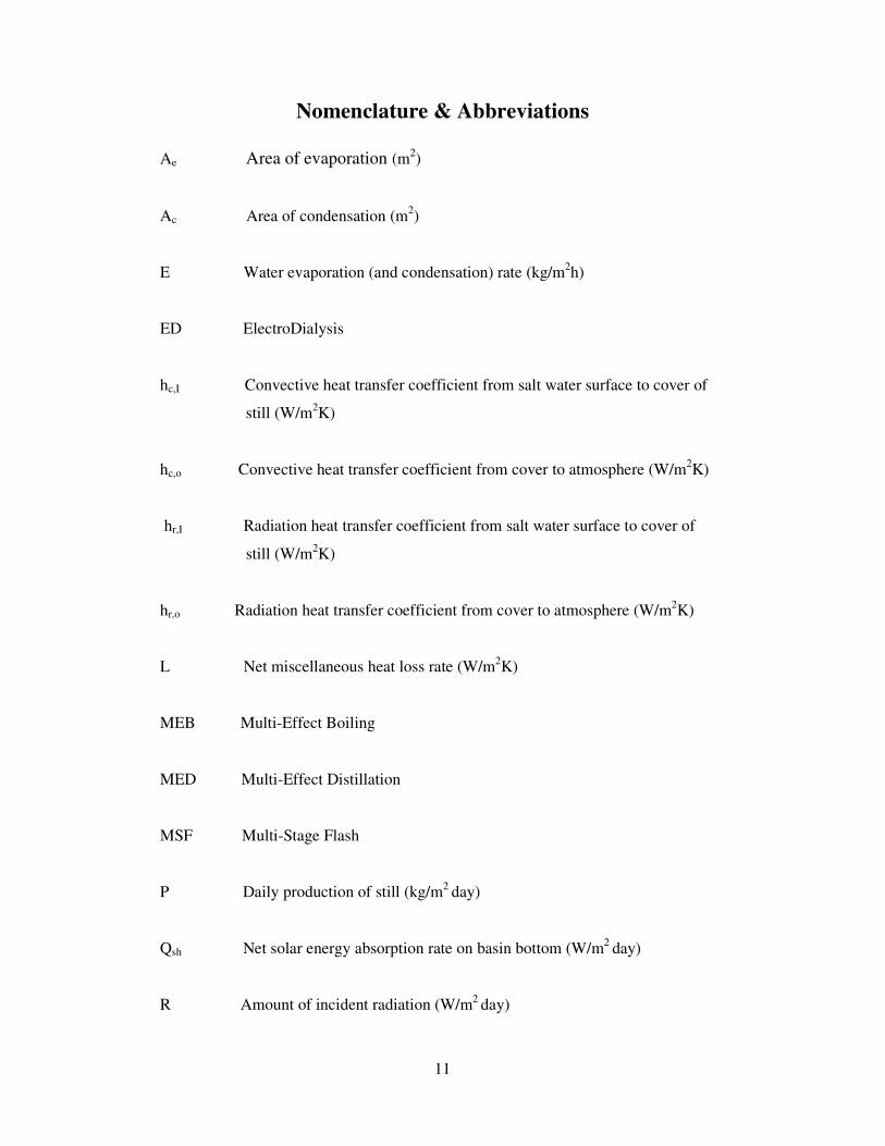
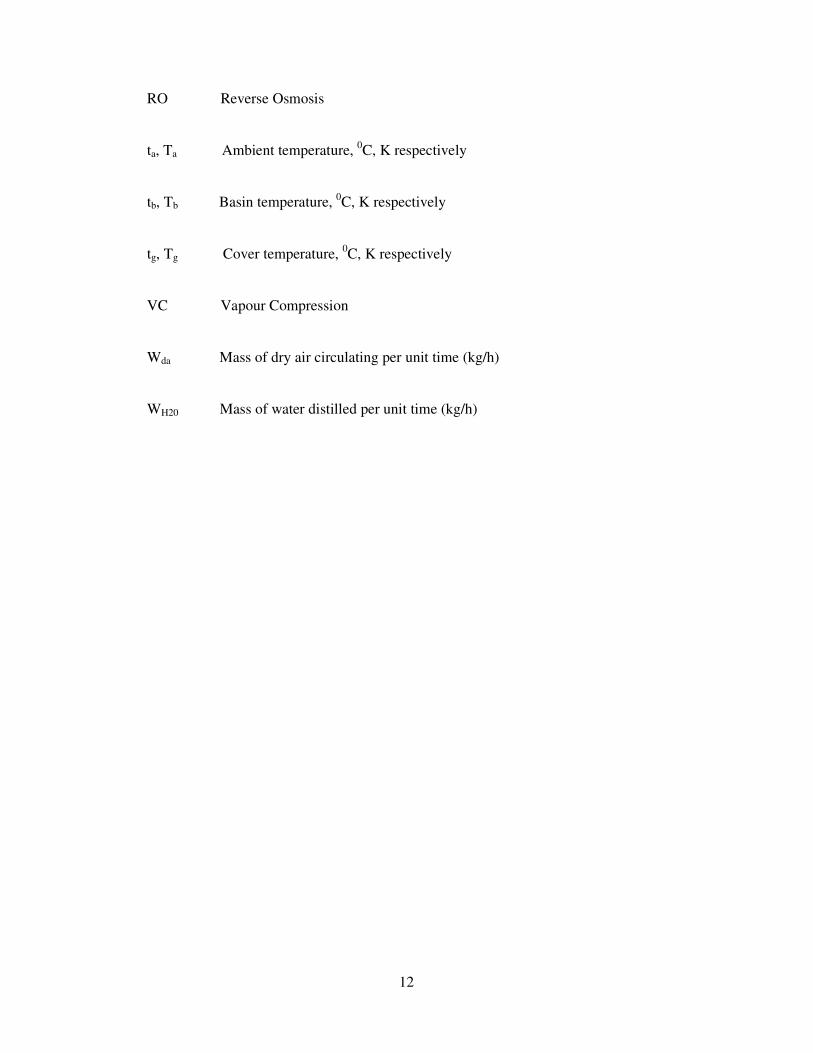

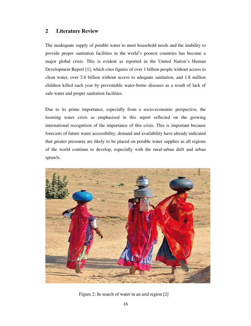


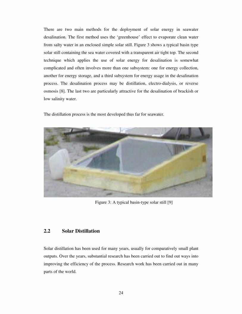
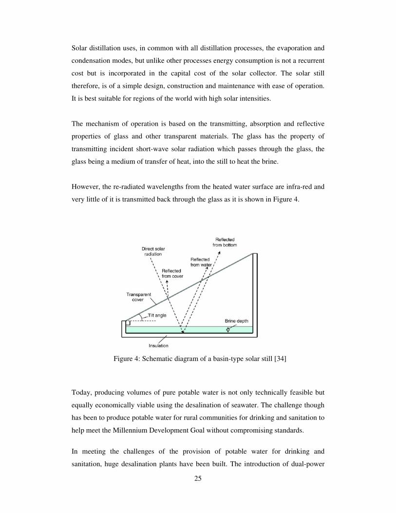
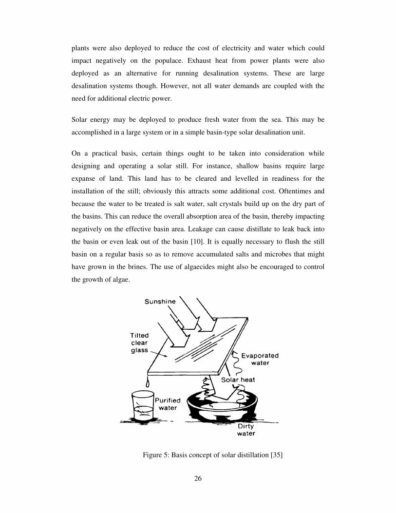

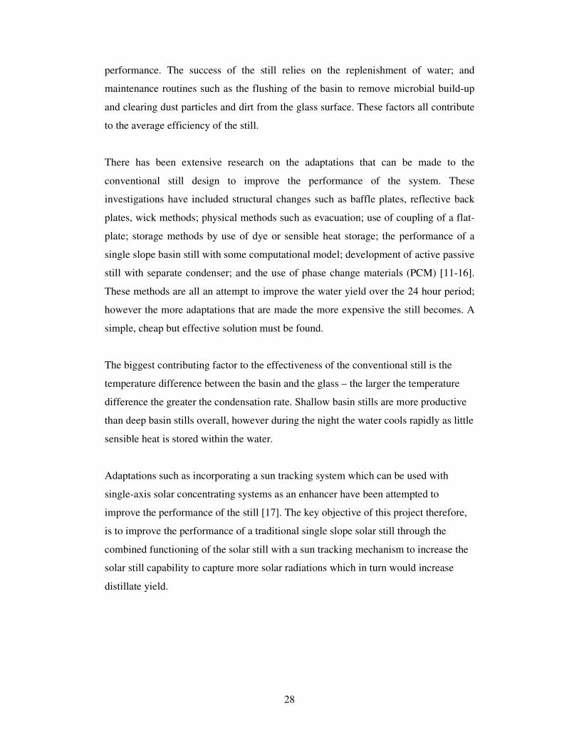
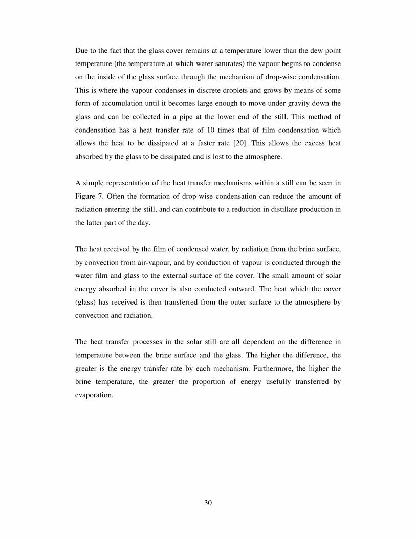
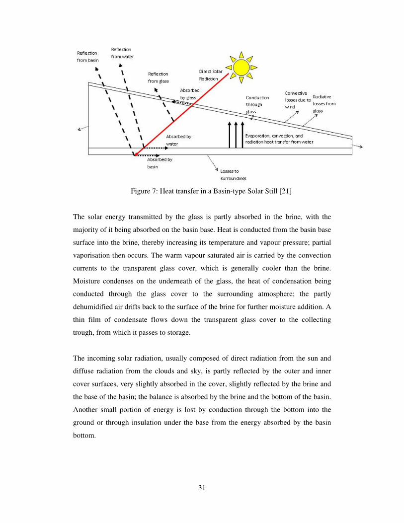

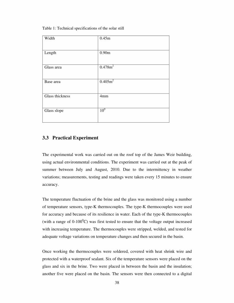
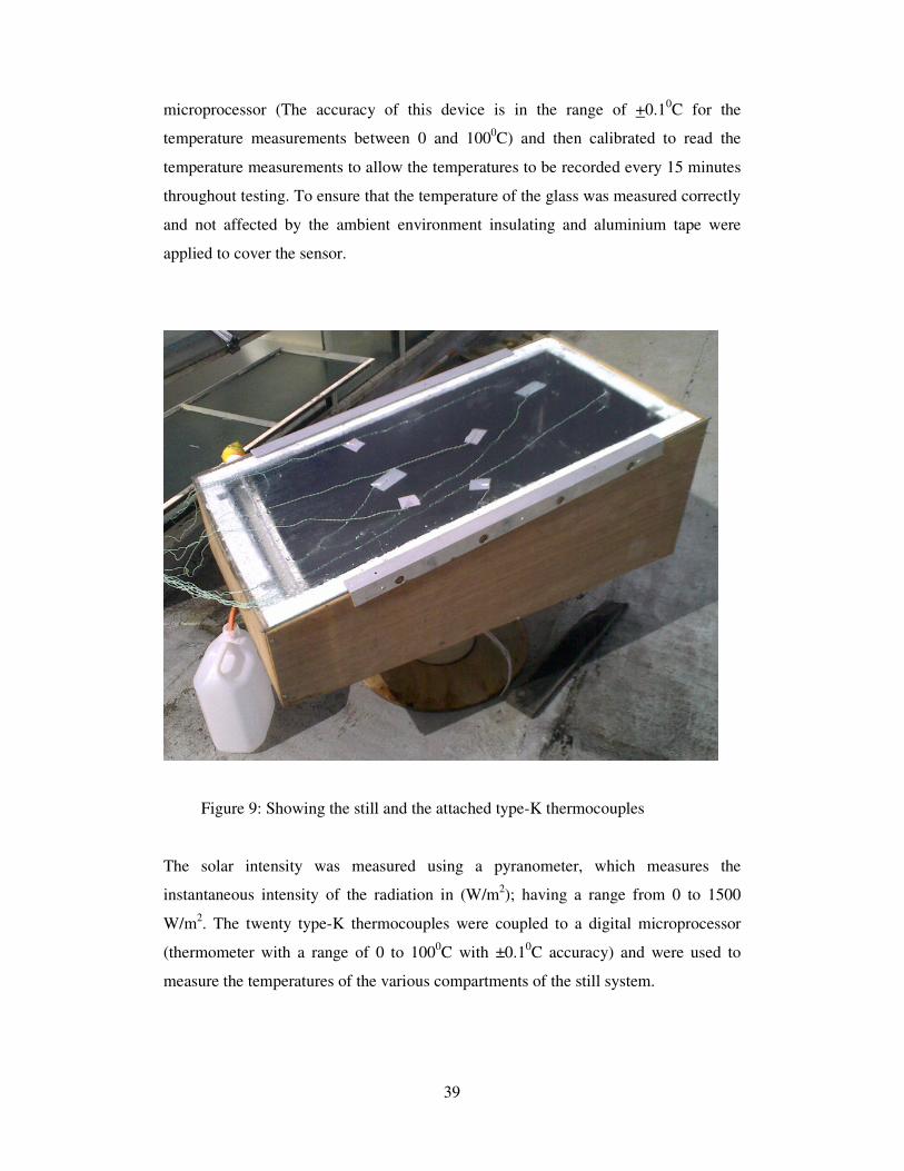

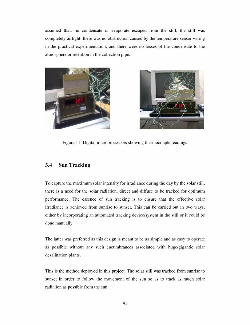

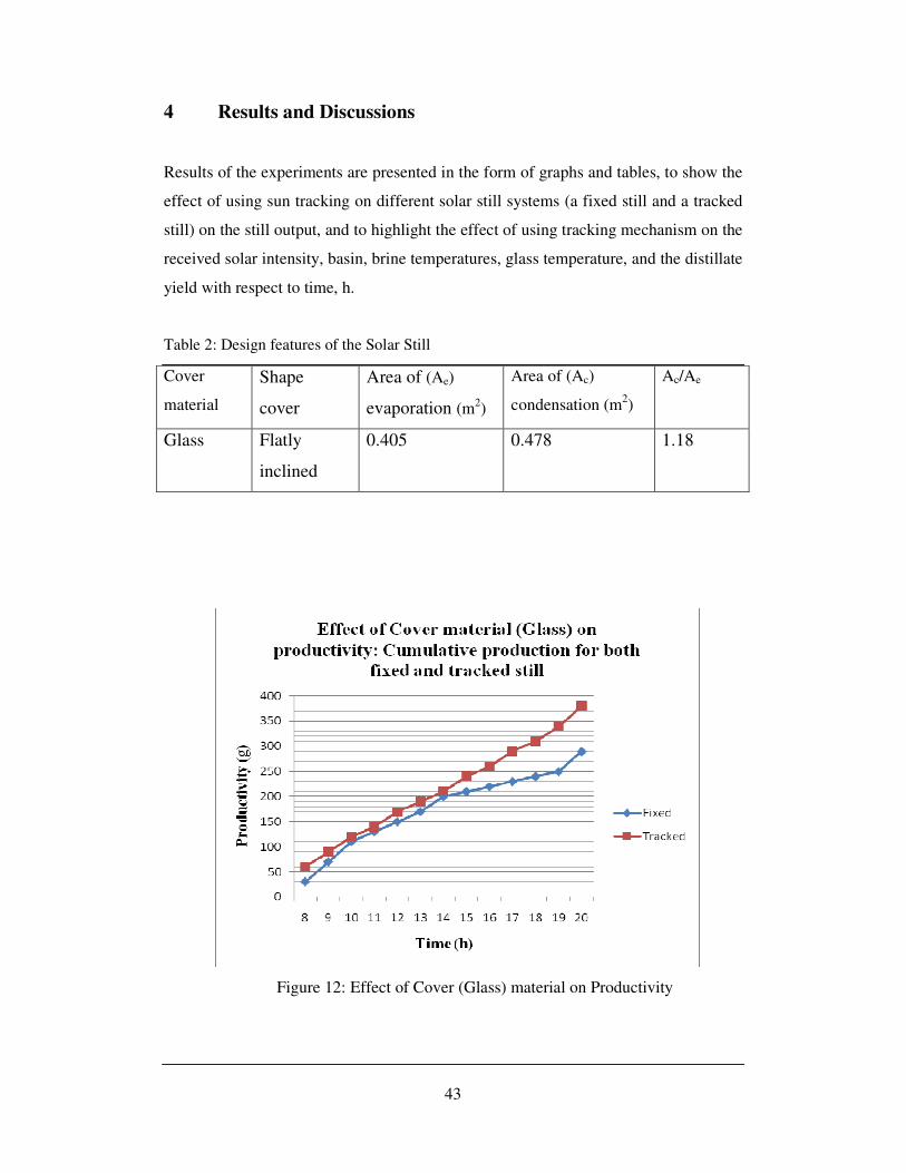
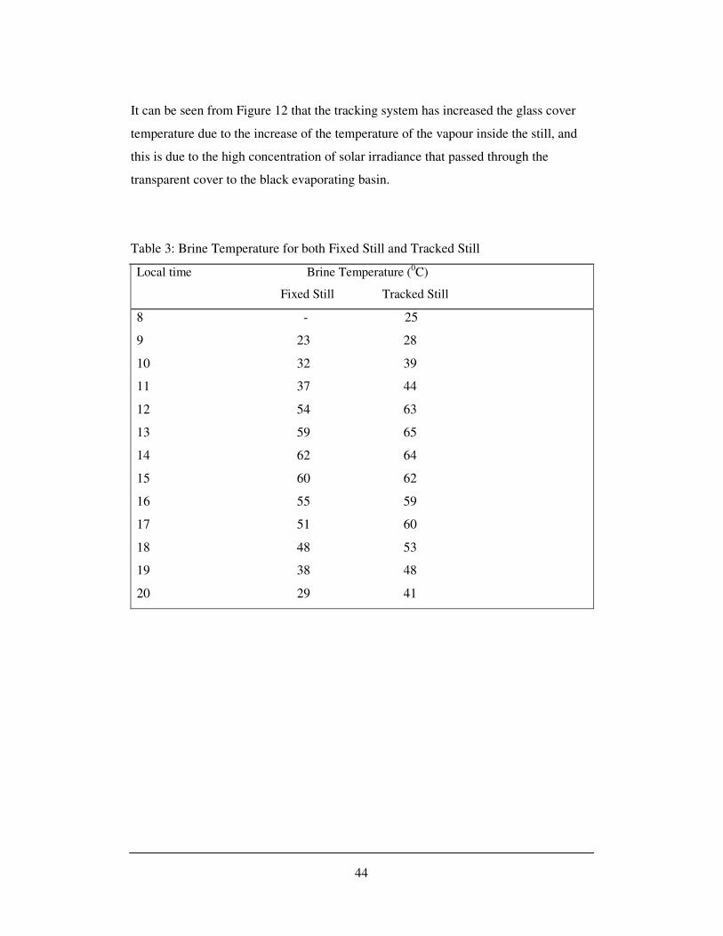
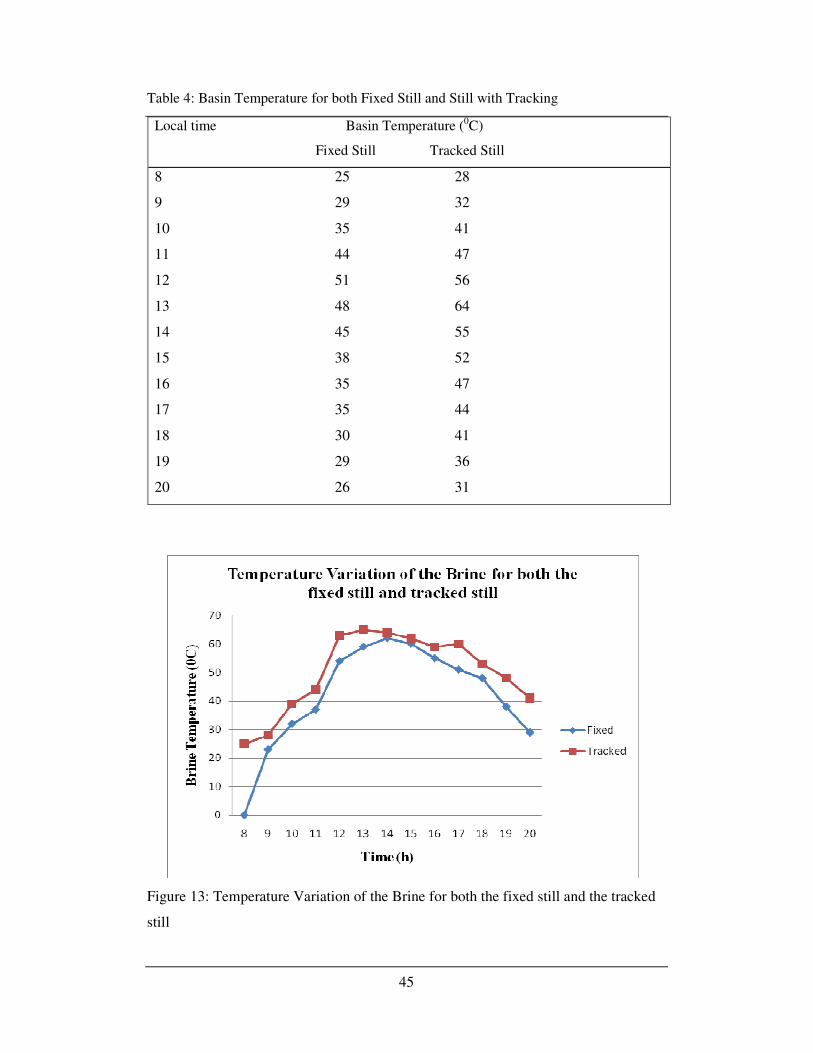

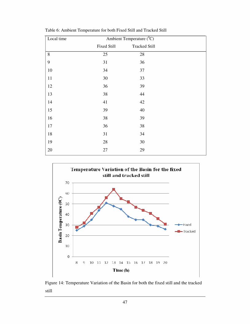
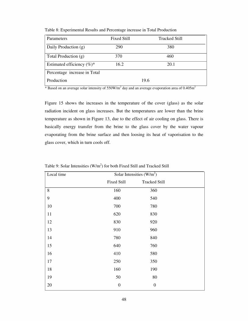
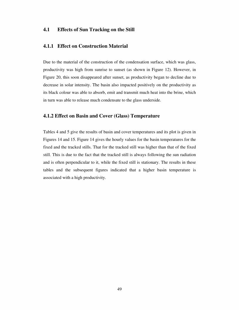
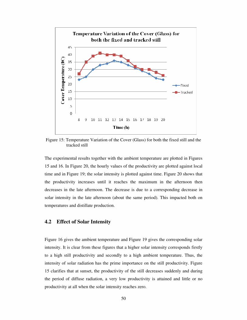
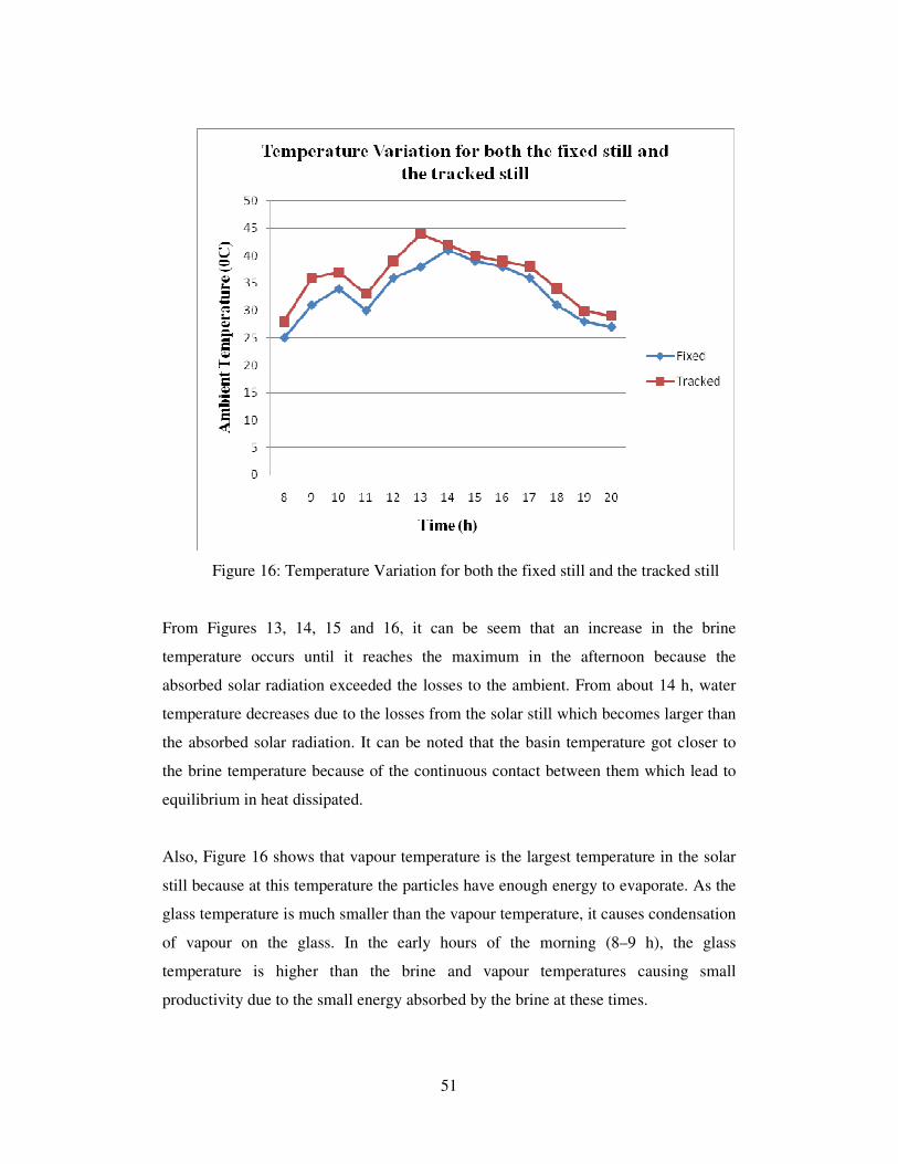
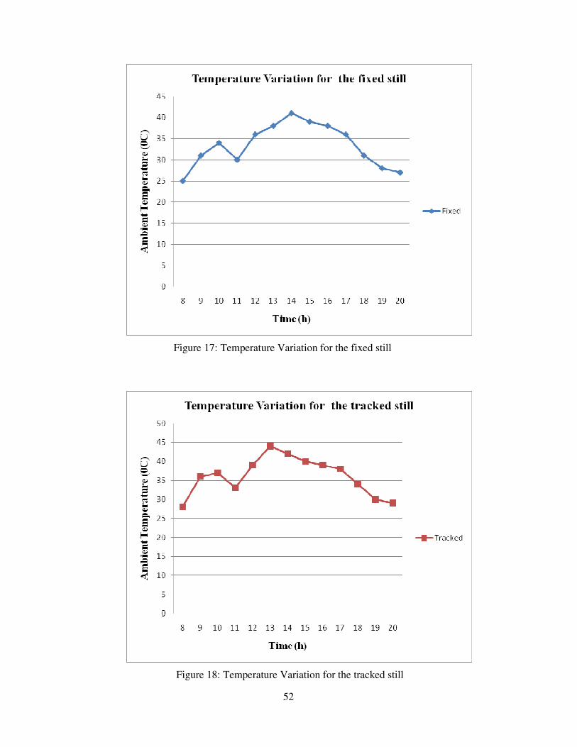
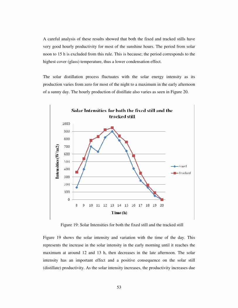

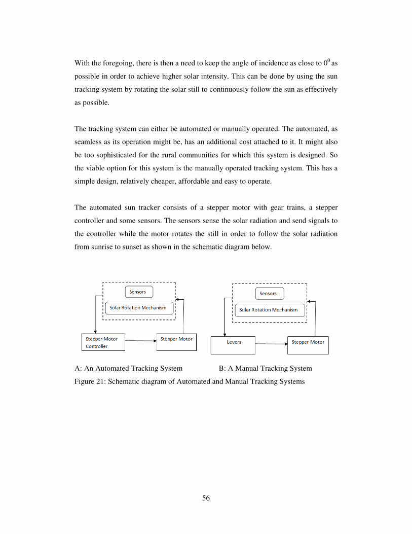


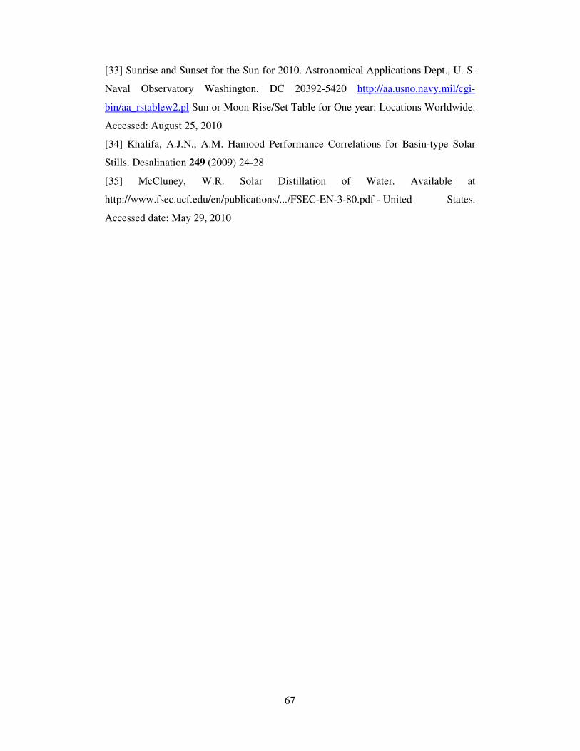
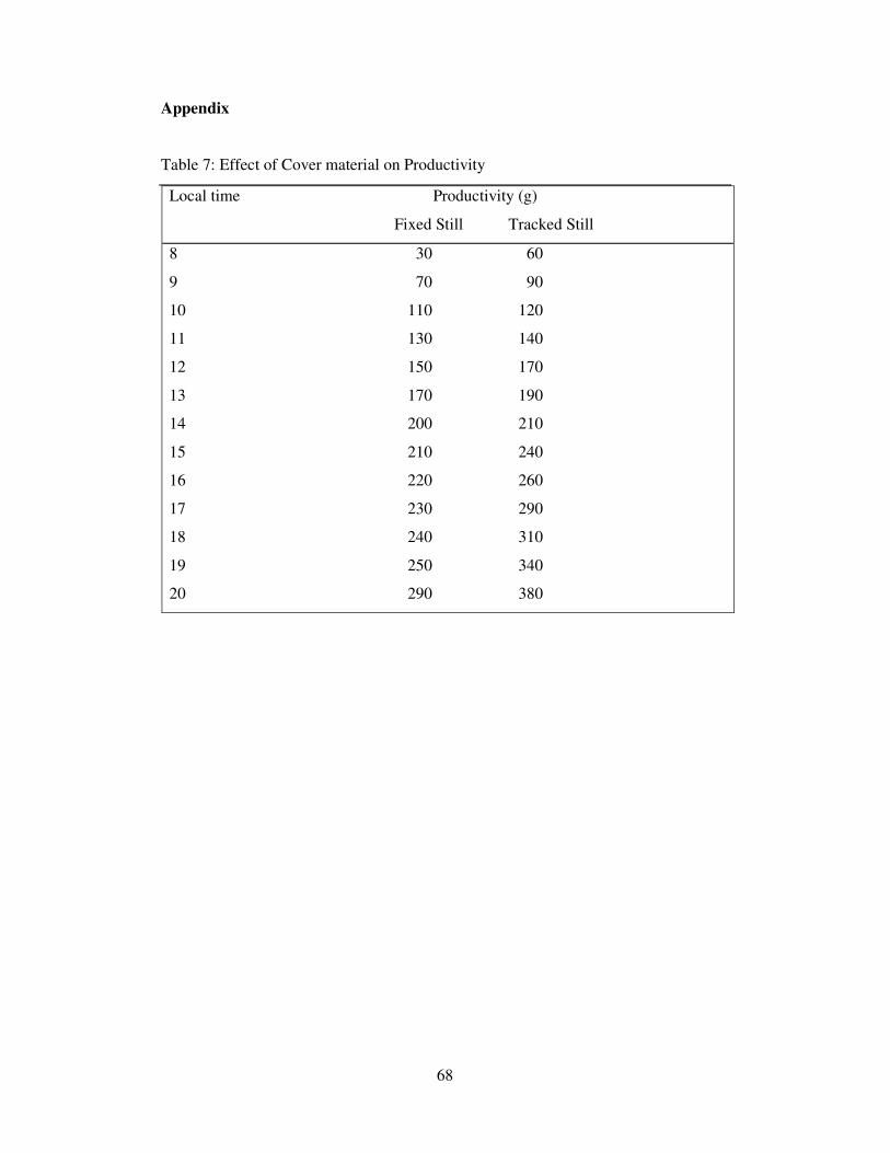
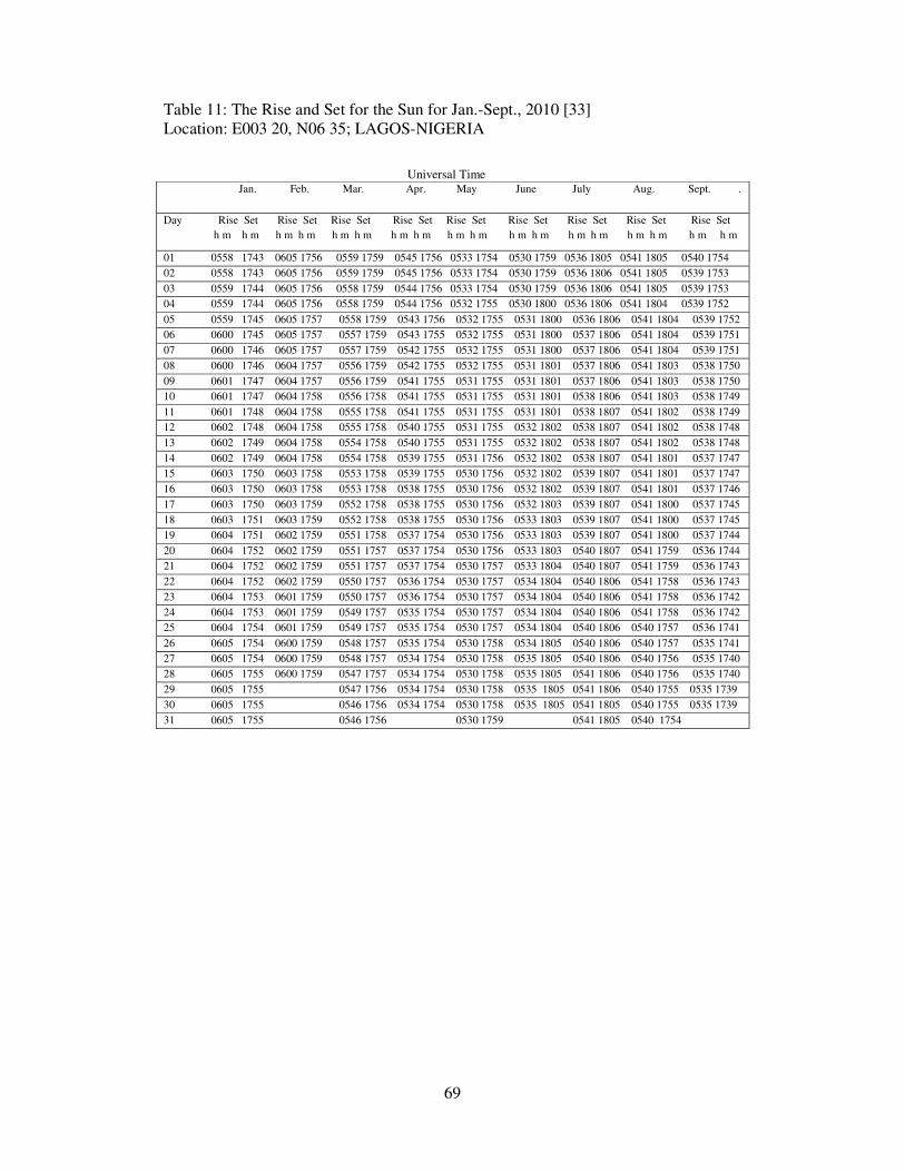


![[Stephen Stills] Illegal Stills(BookFi.org)](https://static.documents.pub/doc/80x56/56d6bfa41a28ab3016970f12/stephen-stills-illegal-stillsbookfiorg.jpg)


