IMPROVING THE SAFETY OF MOVING LANE CLOSURES – PHASE II Prepared By Douglas Steele William Vavrik University of Illinois at Urbana Champaign Research Report ICT-10-072 A report of the findings of ICT-R27-72 Improving the Safety of Moving Lane Closures – Phase II Illinois Center for Transportation August 2010 CIVIL ENGINEERING STUDIES Illinois Center for Transportation Series No. 10-072 UILU-ENG-2010-2013 ISSN: 0197-9191
Transcript
IMPROVING THE SAFETY OF MOVING LANE
CLOSURES – PHASE II
Prepared By
Douglas Steele William Vavrik
University of Illinois at Urbana Champaign
Research Report ICT-10-072
A report of the findings of ICT-R27-72
Improving the Safety of Moving Lane Closures – Phase II
Illinois Center for Transportation
August 2010
CIVIL ENGINEERING STUDIES Illinois Center for Transportation Series No. 10-072
UILU-ENG-2010-2013 ISSN: 0197-9191
Technical Report Documentation Page
1. Report No.
FHWA-ICT-10-072
2. Government Accession No. 3. Recipient's Catalog No.
4. Title and Subtitle
Improving the Safety of Moving Lane Closures – Phase II
5. Report Date
August 2010 6. Performing Organization Code
8. Performing Organization Report N o. 7. Author(s)
Douglas Steele and William Vavrik ICT-10-072 UILU-ENG-2010-2013
9. Performing Organization Name and Address
Applied Research Associates, Inc. 100 Trade Centre Drive, Suite 200 Champaign, IL 61820
10. Work Unit ( TRAIS)
11. Contract or Grant No.
ICT R27-72 13. Type of Report and Period Covered
12. Sponsoring Agency Name and Address
Illinois Department of Transportation Bureau of Materials and Physical Research 126 E. Ash Street Springfield, IL 62704
14. Sponsoring Agency Code
15. Supplementary Notes
16. Abstract Moving lane closures are an increasingly utilized and potentially hazardous traffic control procedure for highway maintenance and operations activities. To improve the safety of moving lane closures for workers and motorists, this study investigated driver behavior around and in moving lane closures and the effect of different components of current traffic control scenarios, including the number, configuration, and spacing of shadow vehicles, and the effect of various traffic control devices and sign messages. This report presents the study’s Phase II efforts, including a series of large group meetings, an expert panel review of the findings, and recommendations for revisions to traffic control standards to improve the safety of moving lane closures for highway workers and the traveling public. The Phase I findings, including the results of full-scale field experiments, were reported previously.
17. Key Words
Moving lane closures, mobile lane closures, rolling lane closures, work zone safety, highway maintenance, highway operations, truck-mounted attenuators, portable changeable message systems, traffic control standards
18. Distribution Statement
No restrictions. This document is available to the public through the National Technical Information Service, Springfield, Virginia 22161.
19. Security Classif. (of this report)
Unclassified
20. Security Classif. (of this page)
Unclassified
21. No. of Pages
22. Price
Form DOT F 1700.7 (8-72) Reproduction of completed page authorized
i
ACKNOWLEDGEMENT
This publication is based on the results of ICT-R27-72, Improving the Safety of Moving Lane Closures – Phase II. ICT-R27-72 was conducted in cooperation with the Illinois Center for Transportation; the Illinois Department of Transportation; the Illinois State Toll Highway Authority; and the U.S. Department of Transportation, Federal Highway Administration.
Members of the Technical Review Panel are the following: • Mr. Aaron Weatherholt, IDOT Bureau of Operations(chair) • Mr. John Benda, Illinois Tollway • Mr. James Stumpner, IDOT District 1 • Mr. Mike Zadel, Illinois Tollway • Mr. Scott Kline, AC Pavement Striping • Ms. Patricia Broers, IDOT Bureau of Materials & Physical Research • Mr. Dean Mentjes, FHWA Illinois Division • Mr. Mike Renner, IDOT Bureau of Construction • Mr. James Allen, IDOT Bureau of Safety • Mr. Joe Monroe, IDOT District 8
ii
DISCLAIMER
The contents of this report reflect the view of the authors, who are responsible for the facts and the accuracy of the data presented herein. The contents do not necessarily reflect the official views or policies of the Illinois Center for Transportation, the Illinois Department of Transportation, the Illinois State Toll Highway Authority, or the Federal Highway Administration. This report does not constitute a standard, specification, or regulation.
iii
EXECUTIVE SUMMARY
BACKGROUND This project is the continuation of research performed under Improving the Safety of
Moving Lane Closures, ICT R27-32. Phase I studied the behavior of motorists through full-scale field experiments to evaluate and determine the specific hazards pertinent to moving lane closures and identify ways they can be made safer for workers and motorists. This Phase II report presents specific recommendations for revisions to Illinois Department of Transportation (IDOT) traffic control standards pertaining to moving lane closures for high-speed, multi-lane roadways. These recommendations were developed in conjunction with traffic control professionals throughout Illinois through a series of large group workshops. In addition, preliminary recommendations were reviewed by an expert panel consisting of traffic control experts from throughout the U.S.
USER INPUT AND FEEDBACK This research incorporated the knowledge and experience of professionals regularly
involved with performing traffic control services. Three large group meetings were held throughout Illinois to present the Phase I findings, receive feedback, and identify solutions to common problems. The participants represented a diverse range of expertise, including traffic protection, engineering, administration, equipment manufacture, and law enforcement. In addition, preliminary recommendations for revisions to traffic control standards were presented to an expert panel of professionals from state and federal highway agencies, academic institutions, and research organizations from throughout the U.S. The recommendations were discussed, and feedback from the panel was incorporated into the proposed standards.
FACTORS CONSIDERED As part of this research, the investigators performed an in-depth evaluation of applicable
moving lane closure traffic standards provided by the federal government, IDOT, and the Illinois Tollway. Common design and policy elements were identified, as well as any possible needs not addressed by current standards. Factors affecting traffic control requirements, such as traffic volume, speed, and highway geometry were identified and considered when developing the revised standards. Finally, a detailed analysis was performed of each traffic control component, including work zone components, equipment and personnel, and spacing between vehicles. The component analysis integrated feedback from the large group and expert panel meetings to give each component thorough consideration during the development of the revised standards.
PROPOSED REVISIONS TO APPLICABLE STANDARDS Recommended revisions to existing traffic control standards are presented. Each
standard describes the equipment and personnel required for each scenario, the configuration and spacing of traffic control vehicles, buffer and work space lengths, and appropriate messages for each case. The minimum requirements for the following four base cases were developed:
iv
• Right lane closure • Left lane closure • Center lane closure (three or more traffic lanes per direction) • Two lane closure (one center and one outer lane)
In addition, six optional components to be used when resources are available and
conditions merit are proposed:
• Additional traffic control vehicles in the transition area • Use of a lead truck downstream of the work space • Use of a blocker truck to prevent shoulder passing • Use of an additional warning truck in the advance warning area • Insertion of a buffer truck to increase spacing between the shadow vehicle and
workers • Use of a spotter within the work space to alert workers of upstream traffic
conditions Also, recommendations for three special cases are provided:
• Working at or near horizontal and vertical curves • Working near ramps • Continuously moving operations
Finally, guidance is provided for selecting appropriate spacings for advance warning and
transition vehicles, taking into account factors such as traffic density, speed, roadway geometry, driver nature, and setting.
RECOMMENDATIONS FOR IMPLEMENTATION AND FUTURE RESEARCH Meetings with the Technical Review Panel (TRP) indicated plans to implement these
recommendations into agency policies and train maintenance personnel through revised standards. In addition, there is interest in expanding this study to moving lane closures on two lanes, which constitutes a significant portion of Illinois highway mileage and presents unique safety challenges.
v
TABLE OF CONTENTS
ACKNOWLEDGEMENT ................................................................................................................ I
DISCLAIMER ................................................................................................................................ II
EXECUTIVE SUMMARY ............................................................................................................. III BACKGROUND ............................................................................................................................ III USER INPUT AND FEEDBACK ........................................................................................................ III FACTORS CONSIDERED ............................................................................................................... III PROPOSED REVISIONS TO APPLICABLE STANDARDS ..................................................................... III RECOMMENDATIONS FOR IMPLEMENTATION AND FUTURE RESEARCH............................................ IV
CHAPTER 2 LARGE GROUP DISCUSSIONS ........................................................................... 2 2.1 PURPOSE AND ATTENDEES ..................................................................................................... 2 2.2 SUMMARY OF KEY FINDINGS ................................................................................................... 3
6.2 TRANSITION AREA ............................................................................................................... 18 Purpose .................................................................................................................... 18 Characteristics ......................................................................................................... 19 Problems and Remedies .......................................................................................... 21
6.3 ACTIVITY AREA .................................................................................................................... 22 Purpose .................................................................................................................... 22 Characteristics ......................................................................................................... 22 Problems and Remedies .......................................................................................... 23
6.4 TERMINATION AREA ............................................................................................................. 24 6.5 OPTIONAL COMPONENTS ..................................................................................................... 25
Additional Trucks in the Transition ........................................................................... 25 Lead Truck ............................................................................................................... 25 Blocker Truck ........................................................................................................... 26 Buffer Truck ............................................................................................................. 27 Flagger or Spotter .................................................................................................... 27
CHAPTER 7 PROPOSED REVISIONS TO STANDARDS ....................................................... 29 7.1 DESCRIPTION OF SYMBOLOGY AND COMPONENTS ................................................................ 29 7.2 BASE CASES ....................................................................................................................... 29
vi
Right Lane Closure .................................................................................................. 30 Left Lane Closure ..................................................................................................... 31 Two-Lane Closure (Three or More Traffic Lanes Per Direction) .............................. 32
7.3 OPTIONAL COMPONENTS ..................................................................................................... 33 Additional Truck in the Transition Area .................................................................... 33 Lead Truck ............................................................................................................... 34 Blocker Truck ........................................................................................................... 35 Additional Advance Warning Vehicle ....................................................................... 36 Buffer Truck ............................................................................................................. 37 Spotter in the Work Space ....................................................................................... 37
7.4 SPECIAL SITUATIONS ........................................................................................................... 37 Horizontal and Vertical Curves ................................................................................ 38 Ramps ...................................................................................................................... 39 Continuously Moving Operations ............................................................................. 41
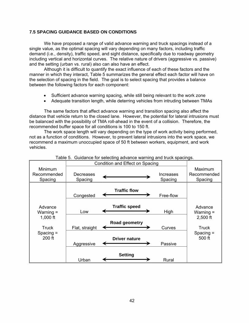
7.5 SPACING GUIDANCE BASED ON CONDITIONS .......................................................................... 42
APPENDIX A - APPLICABLE STANDARDS ............................................................................ 44
1
CHAPTER 1 INTRODUCTION
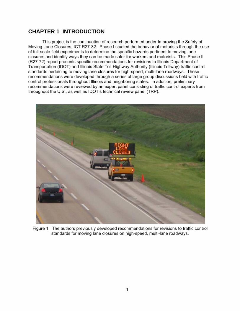
This project is the continuation of research performed under Improving the Safety of Moving Lane Closures, ICT R27-32. Phase I studied the behavior of motorists through the use of full-scale field experiments to determine the specific hazards pertinent to moving lane closures and identify ways they can be made safer for workers and motorists. This Phase II (R27-72) report presents specific recommendations for revisions to Illinois Department of Transportation (IDOT) and Illinois State Toll Highway Authority (Illinois Tollway) traffic control standards pertaining to moving lane closures for high-speed, multi-lane roadways. These recommendations were developed through a series of large group discussions held with traffic control professionals throughout Illinois and neighboring states. In addition, preliminary recommendations were reviewed by an expert panel consisting of traffic control experts from throughout the U.S., as well as IDOT’s technical review panel (TRP).
Figure 1. The authors previously developed recommendations for revisions to traffic control
standards for moving lane closures on high-speed, multi-lane roadways.
2
CHAPTER 2 LARGE GROUP DISCUSSIONS
2.1 PURPOSE AND ATTENDEES The investigators facilitated a series of three large group meetings throughout Illinois to
present the Phase I findings, receive feedback from traffic control professionals regarding their observations, and identify possible solutions for improving the safety of moving lane closures. The meetings were intended to draw on the knowledge and experience of a diverse pool of professionals involved with traffic control procedures, including participants from IDOT, Illinois Tollway, Federal Highway Administration (FHWA), neighboring states, private traffic control providers, law enforcement, and industry (e.g., equipment providers). IDOT personnel from all nine districts and the central office were invited, including personnel from operations, safety, research, and construction. The dates and locations of the three meetings were as follows:
• IDOT District 8 headquarters, Collinsville – April 28, 2009 • IDOT District 1 headquarters, Schaumburg – May 12, 2009 • Illinois Tollway headquarters, Downers Grove – May 14, 2009
Table 1 summarizes the number of participants at each meeting, by affiliation.
Table 1. Breakdown of participants by affiliation at each meeting. Affiliation
Meeting Location District 8 District 1 Illinois Tollway
IDOT 23 9 9 Illinois Tollway 0 9 13 FHWA 1 1 1 Neighboring states 12 0 2 Private contractors 2 2 7 Law enforcement 3 0 6 Industry 1 1 1 Total 42 22 39
The typical agenda at each meeting consisted of:
• Welcome and introduction • Presentation of Phase I findings and discussion • Lunch • Breakout groups
Identification of hazards Areas that need improvement Solutions
• Large group discussion Presentation of breakout session findings Compile recommended changes or areas of improvement
• Wrap-up Figure 2 is a photo of the breakout session at the District 8 meeting.
3
Figure 2. Participants discuss ways to improve mobile lane closures during breakout sessions
at the large group meeting held at District 8 headquarters.
2.2 SUMMARY OF KEY FINDINGS The large group meetings focused on developing group feedback in three main areas:
• What are the hazards and needs involved with moving lane closures? • What are possible solutions and their feasibility? • What specific revisions to traffic control standards do you recommend?
Feedback was diverse and comprehensive, as summarized in the following section.
Hazards and Needs
• Uniformity and consistency in practice between districts, states, agencies, and activity type (e.g., construction, maintenance, and utilities)
• Advance warning (e.g., clarity and effectiveness) • Intrusions into the taper and work zone • Buffer zones and roll-ahead distances • Terminal areas (e.g., a clear indication of the end of the work zone) • Special conditions, such as ramps and gore areas, left and inner lane closures,
and nighttime closures • Additional manpower and trucks • Increased training
4
Solutions and Feasibility
• Additional manpower, equipment, and police presence • Guidance on what to do in special cases • Improve individual components of the work zone (e.g., the advance warning
• New technologies, such as portable changeable message signs (PCMS), speed feedback signs, and distance range finders
• More worker training, both classroom and practical • Include work zone awareness in drivers training • Increased public awareness, such as Scott’s Law • Consider new legislation, such as reduced work zone speed limits
Recommended Revisions to Traffic Control Standards
• Make the standards uniform across agencies, districts, and states • Provide guidance for choosing spacings (e.g., advance warning, taper, buffer,
and work space lengths) • More effectively inform motorists in the advance warning stage (e.g., through use
of PCMS) • Make standards flexible and allow variations based on site specific conditions,
such as road geometry, traffic volumes, speeds, visibility, day or night, and urban or rural
• Matrix showing how each condition will affect spacings • Additional guidance on truck-mounted attenuators (TMA), such as when to use,
appearance, weight of shadow vehicle, and operational instructions • Policy clarifications or changes (beyond scope of this project), such as when can
a lane be closed, when to forego a moving closure in preference of a stationary lane closure, and whether or not to use a flagger on multi-lane roads
5
CHAPTER 3 EXPERT PANEL MEETING
Following completion of the large group meetings, the investigators presented the findings to the TRP and developed preliminary revisions to the existing traffic control standards. This information was then presented to an expert panel consisting of a diverse group of professionals from across the country to provide peer review. The meeting took place on August 4, 2009, at the Illinois Tollway headquarters in Downers Grove. The following attendees participated:
• Mr. Gerald Ullman, Texas Transportation Institute • Mr. Michael Fontaine, Virginia Transportation Research Council • Mr. Michael Paylor, Maryland State Highway Administration • Mr. Ken Woods, Federal Highway Administration • Mr. Ali Hajbabaie, University of Illinois • Mr. James Sterr, IDOT Office of Chief Counsel • Mr. James Thonn, Energy Absorption Systems • Mr. Marshall Metcalf, IDOT (TRP member) • Mr. Scott Kline, AC Pavement Striping Company (TRP member) • Mr. Dean Mentjes, Federal Highway Administration (TRP member) • Mr. Steve Musser, Illinois Tollway (TRP member) • Mr. Michael Zadel, Illinois Tollway (TRP member) • Mr. John Benda, Illinois Tollway (TRP member) The morning session of the meeting began with a briefing and discussion of the findings
from the Phase I study and large group meetings. In the afternoon, the investigators preesented their preliminary recommendations for revisions to IDOT’s traffic control standards related to moving lane closures. This focused heavily on a base case scenario consisting of a single lane closure of the right lane of a multi-lane roadway using a convoy of three traffic control trucks with arrowboards and attenuators. Several options and variations of this base case were discussed, including:
• Case for workers on foot in the work space • Minimum recommended buffer space between workers and the TMA directly
upstream of them • Maximum recommended length of the work space containing the workers and
equipment • Optional use of a lead truck to increase visibility of the workers in the work space • Optional use of a buffer truck upstream of the TMA protecting the work space to
provide additional distance between the workers and potential point of impact • Options for convoys ranging in number from two to four trucks to form the taper and
close the lane • Minimum and maximum recommended values for spacing between trucks in the
taper • Minimum and maximum recommended upstream spacing for the advance warning
truck • Optional use of an additional advance warning vehicle on the shoulder within the
advance warning area to provide additional guidance
6
Figure 3. The expert panel is briefed on the research team’s findings and recommendations
prior to discussion.
Finally, special situations such as left lane and interior lane closures, working around ramps, working in the vicinity of horizontal and vertical curves, and the use of short taper lengths were discussed with the panel. Overall, the meeting provided excellent feedback and discussion on a topic of interest to many state agencies. In general, the panel was supportive of the preliminary recommendations and provided the following comments regarding key issues:
• Based on the improvement in buffer and work space seen in the field with the lead truck option, it was recommended that this become part of the base case, as opposed to the situation of workers on foot without a lead truck.
• The recommended minimum buffer space of 100 ft met with approval. • The recommended maximum work space of 100 ft (with a lead truck) met with
approval. • The minimum and maximum truck spacings of 200 to 500 ft, respectively, met with
approval; this results in taper lengths ranging from 200 to 1500 ft, depending on whether two, three, or four trucks are used to form the taper.
• The panel strongly advised against using short taper lengths (especially at night), where the total taper length was less than 200 ft, due to a lack of advance warning and the time required for traffic to change lanes.
• The optional use of an additional warning truck in the advance warning area met with approval because it keeps the public’s attention and provides the opportunity to convey additional information to motorists.
7
• The panel liked the idea of the “blocker” truck to prevent shoulder passing and suggested that this may be a better alternative for providing positive protection to workers in front of the lead TMA than the use of short taper lengths.
• The continued integration and use of PCMS’s instead of static signs was supported, although these devices may not be available to all traffic control crews.
• The panel recommended further research on reducing the number of flashing lights on trucks during nighttime testing, as this may be causing confusion to motorists.
• An identity for moving lane closures should be developed to distinguish them from construction work zones, bridge work, utility work, and so on, as it is to the motorists’ advantage—especially in urban areas—to know that a moving lane closure is being used, rather than a static closure, as this gives the expectation of a short delay.
8
CHAPTER 4 FACTORS CONSIDERED FOR STANDARD DEVELOPMENT
The design of traffic control standards is as complex as it is important, taking into account a diverse range of factors to develop procedures that are safe and practical to protect workers and the traveling public, within the resources available and under a wide range of field conditions. Many important factors were considered during the course of this research, as listed below:
• Traffic characteristics Volumes Density (congested or free-flowing) Speed Driver characteristics (urban vs. rural) Level of aggressiveness Impairment or distraction
• Roadway features Horizontal and vertical curves Ramp exits and entrances
• Weather conditions Visibility Precipitation
• Time of day (day or night) • Type of work activity
Moving or intermittent Work equipment or vehicles Workers on foot
• Duration of lane closure (intermittent activities) • Traffic control resources available
Manpower and trucks Safety equipment (e.g., arrowboards and attenuators) PCMS’s and static signs
As illustrated in figure 4, the optimal traffic control procedures vary from road to road,
and may even vary for the same road depending on the prevailing conditions at the time of the work activity. For example, a road that has fast-moving, free-flowing traffic at one time of day may be congested during peak hours. Therefore, a “one size fits all” approach to traffic control is not recommended. The preferred approach is to define an acceptable range of values for key parameters, such as truck spacing, buffer space length, and work zone length, to account for varying field conditions. For example, in the case of truck spacing, when traffic is moving at high speeds the trucks should be spaced as far apart as safely allowable to provide adequate sight distance. As traffic density increases and speeds decrease, truck spacing can be decreased to reduce the potential for intrusions.
The Manual on Uniform Traffic Control Devices (MUTCD) recognizes this dynamic when discussing advance warning distances. Table 6C-1 in the MUTCD presents recommended spacings between signs based on roadway functional class and speed; however, the guide states, “These distances should be adjusted for field conditions, if necessary, by increasing or decreasing the recommended distances.” As field conditions change, the optimal spacing between trucks may change. For example, in the case of the free-flowing traffic shown in Figure 4 (a), trucks should be spaced as
9
far apart as possible to provide adequate warning to traffic approaching the work zone. On the other hand, as traffic becomes congested and speeds decrease, as shown in Figure 4 (b), it may be necessary to reduce truck spacing to prevent intrusions. Therefore, specifying a range of valid truck spacings is preferable to a single distance.
(a)
(b)
Figure 4. (a) Free-flowing traffic where trucks should be spaced far apart to provide adequate warning; (b) Congested traffic where reduced truck spacing is necessary to reduce intrusions.
10
Finally, it was determined with the TRP that several of the above factors are best characterized as policy decisions and are therefore beyond the scope of this research. As such, several components, including weather conditions, time of day, type of work activity, and duration of lane closure are not addressed in this report. The available traffic control resources (such as manpower and trucks) were taken into account by making a base case of minimal requirements that should be available for all maintenance yards, and proposing optional components recommended for use when needed and as the resources are available.
11
CHAPTER 5 APPLICABLE TRAFFIC CONTROL STANDARDS
The Phase I study reviewed and summarized literature and documents pertaining to moving lane closures, including identification of applicable Federal, IDOT, and Illinois Tollway standards. The following documents and standards were identified as being applicable to the scope of this study, meaning moving or intermittent lane closures for high-speed, multi-lane roads. The applicable standards are listed and reviewed in this section to identify components, design criteria, and traffic control requirements addressed by each, and included in appendix A for reference.
5.1 APPLICABLE STANDARDS
Manual on Uniform Traffic Control Devices for Streets and Highways (MUTCD), Part 6 Temporary Traffic Control, 2003 Edition.
• Typical Application 35 – Mobile operation on a multilane road IDOT Work Site Protection Manual: For Operations Activities and Emergency Callouts,
Issue #8, August 2005.
• WZ40 – All speeds multi-lane up to 60 minutes • WZ46 – All speeds, intermittent/moving operation, no time limit, more than 4 mile per
day • WZ46A – All speeds, intermittent/moving operation, no time limit, more than 4 mile per
day • WZ47 – 45 mph or less, intermittent/moving operation with curb and gutter, one lane
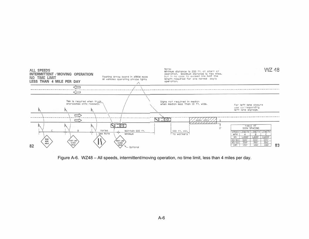
closure • WZ48 – All speeds, intermittent/moving operation, no time limit, less than 4 mile per day • WZ49 – Intermittent/moving operation, two lane closure • WZ52 – All speeds, multi-lane moving operation • WZ63 – Moving operation for work at entrance ramp (15 min and less); used with WZ46
or 46A
IDOT Supplement to the Work Site Protection Manual: Other than Highway Maintenance and Traffic Crews, Issue #6A, February 2001.
• WZ40 – All speeds multi-lane up to 60 minutes • WZ 48 – All speeds, intermittent/moving operation, no time limit, less than 4 mile per day • WZ49 – Intermittent/moving operation, two lane closure • WZ52 – All speeds, multi-lane moving operation
IDOT Standard 701426-02, Lane closure, multilane, intermittent or moving operations for
speeds >= 45 mph, January 1, 2005. Details A, B, C, and D. Illinois Tollway Roadway Traffic Control and Communications Guidelines, Revision 0.0,
August 2005.
• Plate 10 – Moving operation, single lane closure • Plate 11 – Moving operation, two lane closure
12
5.2 TYPICAL COMPONENTS, DESIGN CRITERIA, AND REQUIREMENTS
Review of the standards showed several common elements for when, why, and how long to use each protocol. These factors are a combination of policy decisions and design criteria, including:
• Number of lanes in the traffic direction • Number of lanes to be closed • Traffic speed • Duration of work activity • Nature of work activity (e.g., moving or intermittent) • Length of roadway traversed during the day (IDOT only)
The standards typically show “how” to perform each operation in a diagram containing
elements, such as the required traffic control resources and layout to be used for each scenario. These include:
• Number of trucks • Whether or not to use static signs upstream of the trucks (IDOT only) • Spacing between trucks • Spacing between trucks and signs (if applicable) • Length of buffer space between the lead truck and workers • Length of work space
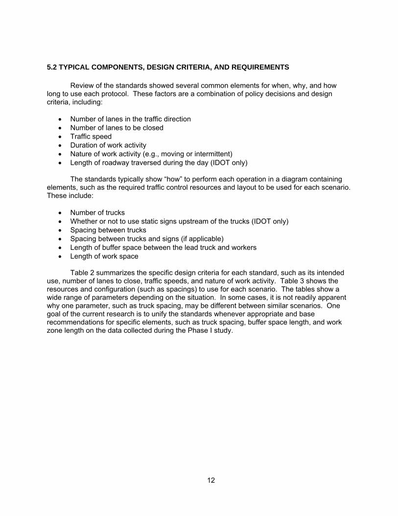
Table 2 summarizes the specific design criteria for each standard, such as its intended use, number of lanes to close, traffic speeds, and nature of work activity. Table 3 shows the resources and configuration (such as spacings) to use for each scenario. The tables show a wide range of parameters depending on the situation. In some cases, it is not readily apparent why one parameter, such as truck spacing, may be different between similar scenarios. One goal of the current research is to unify the standards whenever appropriate and base recommendations for specific elements, such as truck spacing, buffer space length, and work zone length on the data collected during the Phase I study.
13
Table 2. Purpose and design conditions of each standard.
Agency
Standard No. of Lanes in Traffic Direction
No. of Lanes to be Closed
Traffic Speeds
Duration of Work Activity
Nature of Work Activity
Distance Traveled
MUTCD TA 35
≥ 2
1
Not stated
Not stated
Intermittent/ moving
IDOT
WZ40
≥ 2
1
All
≤ 60 min
Intermittent/ moving
WZ46
≥ 2
1
All
No time limit
Intermittent/ moving
≥ 4 mi/day
WZ46a
≥ 2
1
All
No time limit
Intermittent/ moving
≥ 4 mi/day
WZ47
≥ 2
1
≤ 45 mph
Not stated
Intermittent/ moving
WZ48
≥ 2
1
All
No time limit
Intermittent/ moving
≤ 4 mi/day
WZ49
≥ 3
2
Not stated
Not stated
Intermittent/ moving
WZ52
≥ 2
1
Not stated
Moving
WZ63a
≥ 2
1+ramp
Not stated
≤ 15 min
Intermittent/ moving
ILLINOIS TOLLWAY
Plate 10
≥ 2
1
Not stated
Moving
Plate 11
≥ 3
2
Not stated
Moving
a Used in conjunction with either WZ46 or WZ46a.
14
Table 3. Resources and layout specified by each standard.
Agency
Standard No. of Trucks Advance
Warning Signs?a Spacing Between Trucks and Signs
Buffer Space Length
Work Space Length
MUTCD TA 35
2 or 3
No
Variable
Variable
Not stated
IDOT
WZ40
2
Yes
Variable based on speed
100-ft minimum
Not stated
WZ46
2
No
200 to 1500 ft
100-ft minimum
Not stated
WZ46a
3
No
1000 ft
100-ft minimum
Not stated
WZ47
1
No
100-ft minimum
Not stated
WZ48
2
Yes
600 ft and variable based on speed
100-ft minimum
Not stated
WZ49
4
No
600-ft minimum and 500 to 1500 ft
100-ft minimum
Not stated
WZ52
2
No
500 ft variable
100-ft minimum
Not stated
WZ63a
1 on ramp
No
Not stated
Not stated
ILLINOIS TOLLWAY
Plate 10
4
No
500, 500 and 1500 ft
Not stated
Not stated
Plate 11
4
No
750, 750, and 1500 ft
Not stated
Not stated
a Static signs upstream of the advance warning truck and in addition to any signs on trucks.
15
CHAPTER 6 COMPONENT ANALYSIS
As part of developing revised moving lane closure standards, the research team performed a component analysis of each element included in the standards to determine its function, typical attributes, and other important information. For example, in the case of the advance warning area, the investigators defined its purpose, typical spacing upstream of the work zone, and the consequences of not having sufficient advance warning. This component analysis was based on existing standards, observations from the Phase I field tests, input from the large group and expert panel meetings, and discussions with the TRP members. The following components were considered and are discussed in this section:
Work Zone Components
• Advance warning area • Transition area • Activity area (buffer and work spaces) • Termination area
Vehicles and Equipment
• Shadow vehicles with TMA’s and arrowboards • Advance warning vehicles with signs or PCMS’s • Lead truck • Blocker truck • Buffer truck • Flagger or spotter
Spacings and Lengths
• Advance warning length • Transition length • Buffer space • Work space
The MUTCD defines the components of a Temporary Traffic Control (TTC) zone into
four areas, as shown in figure 5. The IDOT Work Site Protection Manual presents a similar definition of work zone components in Standard WZ10. Although this concept typically is used for stationary work zones using traffic control devices such as traffic drums as delineators, the MUTCD does not provide a separate diagram defining the components of a moving lane closure. Since moving lane closures contain similar components as stationary lane closures, we have adopted the MUTCD definitions in figure 5 for use in this study and discussion in the following sections.
16
Figure 5. Components of a temporary traffic control zone (MUTCD figure 6C-1).
17
6.1 ADVANCE WARNING AREA Purpose
According to the MUTCD, the advance warning area is the “section of highway where
road users are informed about the upcoming work zone or incident area.” Although this definition only mentions warning motorists of the upcoming lane closure, typically the majority of motorists also transition to the open lane in this area, especially under low-volume or free-flowing traffic conditions. This is preferable to traffic entering into the transition area prior to vacating the closed lane. Characteristics
In the case of stationary TTC zones, advance warning typically is provided by means of a series of static signs placed upstream of the work zone. Moving lane closures often are not afforded this opportunity, however, as the continuously advancing nature of the operation makes the setup and breakdown of static signs impractical. Therefore, advance warning for moving lane closures is provided by a truck equipped with a static sign or PCMS positioned on the shoulder at an appropriate distance upstream. Figure 6 shows examples of typical advance warning vehicles and signage.
Figure 6. Examples of advance warning vehicles and signage. A truck equipped with a
static sign (left) and a pickup truck with a PCMS.
Based on the field tests and meeting feedback, there is a strong preference for PCMSs over static signs, as they allow greater flexibility in messages, including alternating messages that convey more information to motorists. The PCMSs have larger letters sizes, which increases visibility, making them especially advantageous at night. One disadvantage of PCMSs, however, is they may become “washed out” due to ambient sunlight.
Both the MUTCD and IDOT standards recognize that advance warning distances should vary with traffic speed, specifying greater distances for higher speeds. In the case of the MUTCD guidelines, which are developed for stationary TTC zones, the recommended distances between signs for expressways/freeways range from 1,000 to 2,640 ft. IDOT standards for moving lane closures that include static signs upstream of the transition trucks (i.e., WZ40 and WZ48) recommend spacings from 350 to 2640 ft depending on traffic speed and scenario (for traffic speeds ranging from 45 to 65 mph).
18
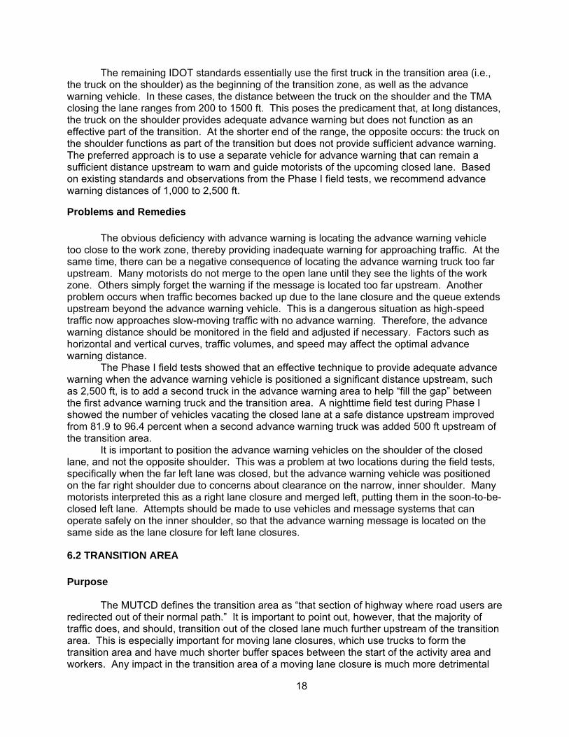
The remaining IDOT standards essentially use the first truck in the transition area (i.e., the truck on the shoulder) as the beginning of the transition zone, as well as the advance warning vehicle. In these cases, the distance between the truck on the shoulder and the TMA closing the lane ranges from 200 to 1500 ft. This poses the predicament that, at long distances, the truck on the shoulder provides adequate advance warning but does not function as an effective part of the transition. At the shorter end of the range, the opposite occurs: the truck on the shoulder functions as part of the transition but does not provide sufficient advance warning. The preferred approach is to use a separate vehicle for advance warning that can remain a sufficient distance upstream to warn and guide motorists of the upcoming closed lane. Based on existing standards and observations from the Phase I field tests, we recommend advance warning distances of 1,000 to 2,500 ft.
Problems and Remedies
The obvious deficiency with advance warning is locating the advance warning vehicle too close to the work zone, thereby providing inadequate warning for approaching traffic. At the same time, there can be a negative consequence of locating the advance warning truck too far upstream. Many motorists do not merge to the open lane until they see the lights of the work zone. Others simply forget the warning if the message is located too far upstream. Another problem occurs when traffic becomes backed up due to the lane closure and the queue extends upstream beyond the advance warning vehicle. This is a dangerous situation as high-speed traffic now approaches slow-moving traffic with no advance warning. Therefore, the advance warning distance should be monitored in the field and adjusted if necessary. Factors such as horizontal and vertical curves, traffic volumes, and speed may affect the optimal advance warning distance. The Phase I field tests showed that an effective technique to provide adequate advance warning when the advance warning vehicle is positioned a significant distance upstream, such as 2,500 ft, is to add a second truck in the advance warning area to help “fill the gap” between the first advance warning truck and the transition area. A nighttime field test during Phase I showed the number of vehicles vacating the closed lane at a safe distance upstream improved from 81.9 to 96.4 percent when a second advance warning truck was added 500 ft upstream of the transition area.
It is important to position the advance warning vehicles on the shoulder of the closed lane, and not the opposite shoulder. This was a problem at two locations during the field tests, specifically when the far left lane was closed, but the advance warning vehicle was positioned on the far right shoulder due to concerns about clearance on the narrow, inner shoulder. Many motorists interpreted this as a right lane closure and merged left, putting them in the soon-to-be-closed left lane. Attempts should be made to use vehicles and message systems that can operate safely on the inner shoulder, so that the advance warning message is located on the same side as the lane closure for left lane closures.
6.2 TRANSITION AREA Purpose
The MUTCD defines the transition area as “that section of highway where road users are redirected out of their normal path.” It is important to point out, however, that the majority of traffic does, and should, transition out of the closed lane much further upstream of the transition area. This is especially important for moving lane closures, which use trucks to form the transition area and have much shorter buffer spaces between the start of the activity area and workers. Any impact in the transition area of a moving lane closure is much more detrimental
19
than a transition area consisting of drums or other traffic control devices. In this sense, the transition area can be thought of as the transition of the lane from being fully open to fully closed. It should be the goal of traffic control to transition traffic upstream of the transition area.
In some cases the transition area also performs the function of advance warning, as described in the advance warning section above. If a separate advance warning vehicle is not used, the first warning motorists receive regarding the lane closure occurs at the first vehicle of the transition. Even when an advance warning vehicle is used, motorists may ignore the instructions to vacate the lane until they see the work zone. Characteristics
While stationary TTC zones typically use drums or delineators to form the merging taper, moving lane closures are not afforded this convenience. The MUTCD recognizes this and states, “Because it is impractical in mobile operations to redirect the road user’s normal path with stationary channelization, more dominant vehicle mounted traffic control devices, such as arrow boards, portable-changeable message signs, and high-intensity, rotating, flashing, oscillating, or strobe lights, may be used instead of channelizing devices to establish a transition area.” The number of trucks typically varies from two to four, and they are configured with the truck furthest upstream positioned fully on the shoulder and each successive truck downstream positioned laterally further into the lane. The last truck in the transition is fully in the closed lane and provides positive protection to the work space.
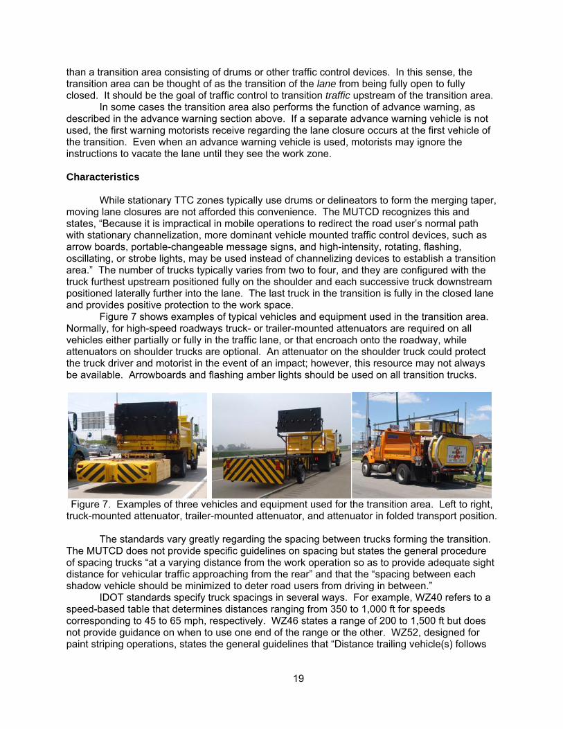
Figure 7 shows examples of typical vehicles and equipment used in the transition area. Normally, for high-speed roadways truck- or trailer-mounted attenuators are required on all vehicles either partially or fully in the traffic lane, or that encroach onto the roadway, while attenuators on shoulder trucks are optional. An attenuator on the shoulder truck could protect the truck driver and motorist in the event of an impact; however, this resource may not always be available. Arrowboards and flashing amber lights should be used on all transition trucks.
Figure 7. Examples of three vehicles and equipment used for the transition area. Left to right,
truck-mounted attenuator, trailer-mounted attenuator, and attenuator in folded transport position.
The standards vary greatly regarding the spacing between trucks forming the transition. The MUTCD does not provide specific guidelines on spacing but states the general procedure of spacing trucks “at a varying distance from the work operation so as to provide adequate sight distance for vehicular traffic approaching from the rear” and that the “spacing between each shadow vehicle should be minimized to deter road users from driving in between.”
IDOT standards specify truck spacings in several ways. For example, WZ40 refers to a speed-based table that determines distances ranging from 350 to 1,000 ft for speeds corresponding to 45 to 65 mph, respectively. WZ46 states a range of 200 to 1,500 ft but does not provide guidance on when to use one end of the range or the other. WZ52, designed for paint striping operations, states the general guidelines that “Distance trailing vehicle(s) follows
20
striping machine will vary depending on terrain…whenever adequate stopping sight distance exists to the rear, the protection vehicle shall maintain minimal distance.”
Based on the Phase I field tests, we recommend truck spacings ranging from 200 to 500 ft, depending on field conditions. Less than 200-ft spacing does not provide adequate sight and reaction distance for motorists that may be approaching the transition at high speeds. Figure 8 illustrates the difficulty a semi-truck has merging on a busy expressway at 40 mph and transition trucks spaced 200 ft apart.
Figure 8. Proximity of a semi-truck to the transition trucks when vacating the closed lane on an expressway with transition trucks spaced 200 ft apart. Left to right, approaching the transition
area, adjacent to the first transition truck, and narrowly avoiding the TMA blocking the lane.
Likewise, 500 ft is about the maximum spacing between trucks that still provides the perspective of a cohesive, continuous transition to motorists. While distances greater than 500 ft may be appropriate for advance warning, they are too large for forming a transition. Figure 9 shows the driver’s view of two trucks spaced 500 ft apart.
21
Figure 9. Driver’s view of trucks spaced 500 ft apart. At distances greater than
500 ft, the trucks form a less cohesive, continuous transition, creating the potential for confusion and intrusions between trucks.
The total transition length will be a function of truck spacing and the number of transition
trucks, as shown in table 4. In general, greater distances should be used for higher traffic or poor sight distance (e.g., due to curves). Shorter spacings should be used for slower-moving traffic and when there is greater potential for intrusions into the transition, such as during congestion.
Table 4. Transition lengths (ft) based on the number of trucks and spacing.
Problems and Remedies The role of the transition trucks is difficult. Too short of a transition length invites
vehicles to remain in the closed lane longer. If the vehicles are spaced too far apart, intrusions may occur. Therefore, constant monitoring of traffic behavior in the field is necessary to determine if truck spacings need adjusting. The preferred solution to the problem of insufficient transition length is to use additional trucks in the transition. This increases the transition length without increasing the spacing between individual trucks. If additional trucks are not available, the spacing can be increased within the guidelines in table 4, but this is less desirable. Another alternative is to add an additional advance warning vehicle upstream. As discussed earlier, advance warning vehicles advise motorists of the upcoming lane closure and effectively move traffic to the open lane.
When intrusions between transition trucks occur, it is advisable to use additional trucks and decrease spacing. If additional trucks are not available, the spacing can be decreased within the above guidelines. If this results in a short taper and vehicles approaching the work zone closely and at high speed, an additional advance warning vehicle upstream can be considered. In general, the requirements for an advance warning vehicle are fewer than those
22
of an additional transition truck (e.g., an attenuator is not required, as the advance warning truck is located on the shoulder), making its availability more likely than an additional TMA.
6.3 ACTIVITY AREA Purpose
Regarding the activity area, the MUTCD says it is “where the work takes place. It is
comprised of the work space, the traffic space, and the buffer space.” The work space is where workers and equipment are located, while the traffic space is the part of the roadway that traffic uses to bypass the work space. There are two types of buffer spaces, lateral and longitudinal. Lateral buffer space is the horizontal clearance between workers and the open traffic lane. Longitudinal buffer space is the clearance between the TMA blocking the lane and the workers.
Characteristics The work space appears in all standards, but its length is never defined. While there is
effectively no limit on work space length for stationary closures using delineators such as drums, moving lane closures obviously have practical limits for the length of roadway that can be occupied by workers and equipment at any given time. Typically, the types of work activities taking place in moving lane closures only require closing a short section of roadway at a time. This means that the work space length can be anywhere from just a few feet to a couple of hundred feet long. Although the research didn’t define a maximum work space length, we feel it is important to consider the “maximum unoccupied work space length” when working in moving lane closures. In other words, if two groups of workers within the work space become longitudinally separated by too great a distance, motorists may interpret this gap as the end of the lane closure and reenter the closed lane too soon. Based on field observations, we do not recommend more than 50 ft of unoccupied roadway within the work space.
Longitudinal buffer space for moving closures is also less than stationary TTC zones. Stationary closures have the advantage of long buffer areas provided by the numerous traffic delineators used to separate traffic from workers. For example, MUTCD table 6C-2 recommends a minimum buffer space of 495 feet for speeds of 55 mph for stationary closures. IDOT’s guide defines a much shorter minimum buffer space of 100 ft for moving lane closures. This shorter distance is necessary to prevent lateral intrusions into the work space. The MUTCD does not specify a buffer distance for mobile closures, only stating “The spacing between the work vehicles and shadow vehicles…should be minimized to deter road users from driving in between.”
This research analyzed the issue of buffer space from two perspectives—a roll-ahead analysis and field tests of actual moving lane closures. The roll-ahead analysis predicted that passenger cars and single-unit trucks moving at 45 mph could push a TMA forward up to 100 ft. Multiple-unit trucks at the same speed could push a TMA forward 100 to 200 ft. Therefore, it is important to maintain a buffer space between the TMA blocking the lane and workers to prevent contact in the event the TMA is impacted from behind by a fast-moving or heavy vehicle.
Unfortunately, just as there is a danger of a TMA being pushed into the work space, there is an opposing hazard of having too much buffer space and the potential for motorists to return to the closed lane too soon (i.e., lateral intrusions). The Phase I field tests showed that, with no workers present, vehicles began returning to the closed lane as early as 50 ft beyond the lead TMA for urban areas and congested conditions. The rural interstate with free-flowing traffic produced reentry distances of 100 ft, as shown in figure 10. With workers present, the buffer space in urban areas was extended safely to 150 ft. At buffer lengths of 200 ft, lateral intrusions began occurring. With a lead truck the buffer distance was extended safely to 200 ft.
23
Based on these results, we recommend a buffer space ranging from 100 to 150 ft (figure 11). The investigators strongly recommend using a lead truck to increase visibility to traffic; however, they recognize that resources may not always be available to do so.
Figure 10. Return distance data for four sites from the Phase I field tests. Urban drivers under a range of conditions returned to the closed lane as soon as 40 to 50 ft beyond the lead TMA,
while rural drivers under free-flow conditions waited until 100 ft to return to the lane.
Problems and Remedies Ensuring adequate buffer space while minimizing the potential for lateral intrusions is a
complicated task. Ideally, there would be a distance where workers are protected against roll-ahead intrusions by the TMA’s impacted from behind by heavy, fast-moving trucks, and at the same time, have minimal risk of lateral intrusions. Unfortunately, the potentially affected zones of these two hazards overlap. This research suggests using as large a buffer space as possible that does not overly expose workers to lateral intrusions—100 to 150 ft.
In addition, visibility of the work crew is vital to preventing lateral intrusions. As a minimum, workers in the work space should wear reflective materials and vehicles should be equipped with flashing amber lights. A lead truck can also be effective in making the work space more visible to passing motorists. Finally, unoccupied work space lengths greater than 50 ft should be avoided.
0
50
100
150
I‐290 at Laramie Ave. I‐90 at Meacham Rd. I‐90 at Barrington Rd. I‐88 at Somonauk Rd.
Return distance, ft
Site
Urban,Congested,
Daytime
Rural,Free-flow,Daytime
Urban,Congested,
Daytime
Urban,Free-flow,Nighttime
24
Figure 11. Maintaining a safe buffer space between workers and the lead TMA is vital;
however, too great a distance can lead to lateral intrusions. The investigators recommend a buffer space no less than 100 ft (shown here) and no greater than 150 ft.
6.4 TERMINATION AREA
The termination area is the area downstream of the work space where traffic is permitted
to return to the closed lane. In stationary closures it typically is designated by a taper established with delineators. The purpose is to provide positive confirmation to motorists that the work zone has ended and that they can return to the closed lane safely.
Termination areas generally are not used for moving lane closures, as there is no practical way of providing a downstream taper due to the moving nature of the operation. The desire to improve communication to motorists at the end of the work zone was mentioned several times in the large group meetings. One possibility is a lead truck downstream of the work space with a PCMS displaying a message such as “End Work Zone”; however, there is concern that this may be misinterpreted by motorists as indicating that they may return to the closed lane prior to the lead truck.
As this research did not identify an indisputable method of providing termination areas for moving lane closures, no recommendations for improvement to the termination area are provided.
25
6.5 OPTIONAL COMPONENTS Additional Trucks in the Transition
The minimum number of trucks required to form a transition is two; however, at times it
can be beneficial to use additional trucks when available and as conditions necessitate. In the field tests, effective use of two to four trucks to form the transition was observed. One benefit of using additional trucks is the ability to lengthen the transition, as shown in table 4 above. Many times, when three trucks are used for a single lane closure, they are positioned such that the middle truck, equipped with a TMA, straddles the lane-shoulder interface. Figure 12 shows examples of the standard two-truck transition and a transition using a third truck. When two lanes are closed simultaneously (e.g., the right and center lanes of a road with three or more lanes in the traffic direction) a minimum of three trucks must be used (i.e., one on the shoulder, one in the right lane, and one in the center lane).
Figure 12. Transition using two trucks (left photo) and three trucks (right photo). The
configuration on the right with three trucks provides a more gradual transition area.
Lead Truck The addition of a lead truck downstream of the work space was mentioned earlier as an
effective means of increasing the visibility of the work space, thereby deterring motorists from returning to the closed lane prior to the end of the work zone. As a minimum, the lead truck should have a flashing amber light. An arrowboard and attenuator are not required; however, they could be advantageous if these resources are available. An arrowboard has the benefit of adding height to the lead truck, making it more visible to motorists, while an attenuator could protect the truck driver and motorist in the event of an impact. Figure 13 shows examples of two lead trucks used in the activity area to increase visibility. Phase I field tests showed that, in both cases, traffic waited longer to return to the closed lane than if there was no lead truck.
26
Figure 13. Two examples of lead trucks used to increase visibility in the activity area. A
truck with TMA and arrowboard (left) and a supervisor’s pickup truck with a strobe light.
Blocker Truck The Phase I field tests in IDOT District 1 showed a good example of using a blocker
truck to prevent vehicles from passing on the shoulder. Figure 14 shows the vehicle used for this purpose and its position during testing. As a minimum, it should be equipped with a flashing amber light. An attenuator is not required; however, it could protect the truck driver and motorist in the event of an impact. This is especially important in urban, congested conditions, as aggressive drivers frequently attempt to make use of the shoulder for passing the work zone, resulting in an obviously dangerous situation for workers.
Figure 14. Example of a blocker truck used in District 1 to prevent traffic from passing
on the shoulder and provide positive protection to the work crew. Note the vehicle in the right lane contemplating passing on the shoulder before merging into the open traffic lane.
This is also a good alternative to the practice of using trucks in very tight configurations
(say, transitions less than 200 ft) to deter vehicles from intruding. When trucks are used in a very tight configuration they do not effectively provide advance warning or transition, rather positive protection against errant vehicles intruding between the trucks. A preferred alternative is to use a blocker truck on the shoulder to provide positive protection and allow the trucks to be spaced further apart, thereby increasing both advance warning and transition distance.
27
Buffer Truck A buffer truck is an additional vehicle used to provide greater distance between the work
crew and the TMA closing the lane. If an impact occurs at the TMA, the extra distance would provide increased safety from flying debris, TMA roll-ahead, and greater reaction time for the workers to flee the work space. The buffer truck is placed downstream between 50 and 100 ft in front of the lead TMA. As a minimum the lead truck should have a flashing amber light. An arrowboard and attenuator are not required; however, they could be advantageous if these resources are available. An arrowboard has the benefit of adding height to the buffer truck, making it more visible to motorists, while an attenuator could protect the truck driver and motorist in the event of an impact. Figure 15 shows an example of a buffer truck being used on a two-lane closure at night.
Figure 15. A buffer truck provides more distance between workers and the TMA closing
the lane, while deterring lateral intrusions into the work space.
Flagger or Spotter
The use of a flagger does not appear in the MUTCD or IDOT standards for moving lane closures of multi-lane roads, with the exception of standard 701426-02 used for contractor provided traffic control. This standard calls for a flagger located midway between the lead TMA and work space, adjacent to the open traffic lane. Throughout the research the investigators encountered strong opposition to placing a flagger in this position due to the exposure to traffic and the lack of benefit in terms of traffic control. The large group meetings revealed several scenarios where a flagger can actually create a safety hazard.
TMA closing lane
Workers on foot
Buffer truck
28
On the other hand, there is widespread support for an observer placed in the work space and dedicated to being the “eyes upstream” of the workers, who may not be able to monitor traffic conditions due to the work activity. The observer should be a person located within arm’s reach of the work crew, positioned to monitor upstream traffic, and prepared to alert the workers if a problem were to develop, such as an errant vehicle. Due to noise and performing the work activity itself, work crews are not always aware of upstream traffic behavior. Figure 16 shows the current IDOT contractor standard using a flagger and the proposed adjustment of making this person a spotter inside the work space.
Figure 16. IDOT construction standard 701426-02, Detail C. We recommend relocating the flagger to the work space to act as a spotter to alert work crews to potential problems
upstream.
29
CHAPTER 7 PROPOSED REVISIONS TO STANDARDS
Based on data collected in Phase I, discussions with professionals in the industry, and consideration of the factors and components discussed in the previous section, the research team developed recommendations for specific elements to incorporate into IDOT’s moving lane closure standards. 7.1 DESCRIPTION OF SYMBOLOGY AND COMPONENTS
To facilitate communication, figure 17 presents the definition of variables and symbology
used to present the standards.
Figure 17. Symbology and nomenclature used to present the recommended standards.
7.2 BASE CASES
We developed recommendations for minimum requirements to safely perform the following four base case scenarios:
• Right lane closure • Left lane closure • Two lane closure (center and one outer lane)
Buffer Space (BS)
Advance Warning
(AW) Area
2
Truck Spacing
(TS)
Work Space (WS)
Activity Area (AA)
Transition Area (TA)
1
LegendTMA
w/arrowboard Work spaceAW truck
w/message
A
A
TMA is required when truck encroaches onto roadway
30
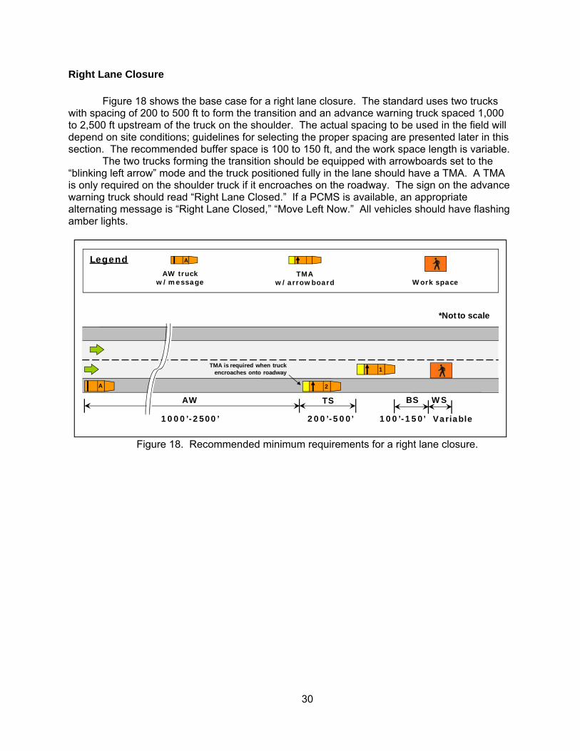
Right Lane Closure Figure 18 shows the base case for a right lane closure. The standard uses two trucks
with spacing of 200 to 500 ft to form the transition and an advance warning truck spaced 1,000 to 2,500 ft upstream of the truck on the shoulder. The actual spacing to be used in the field will depend on site conditions; guidelines for selecting the proper spacing are presented later in this section. The recommended buffer space is 100 to 150 ft, and the work space length is variable.
The two trucks forming the transition should be equipped with arrowboards set to the “blinking left arrow” mode and the truck positioned fully in the lane should have a TMA. A TMA is only required on the shoulder truck if it encroaches on the roadway. The sign on the advance warning truck should read “Right Lane Closed.” If a PCMS is available, an appropriate alternating message is “Right Lane Closed,” “Move Left Now.” All vehicles should have flashing amber lights.
Figure 18. Recommended minimum requirements for a right lane closure.
1000’-2500’
1
AW
100’-150’
BS WS
Variable
A
*Not to scale
LegendTMA
w/arrowboard Work spaceAW truck
w/message
A
2
TS
200’-500’
TMA is required when truck encroaches onto roadway
31
Left Lane Closure
The case of a left lane closure is a mirror image of the preceding scenario, as shown in figure 19. Note that the advance warning truck is placed on the same shoulder as the lane to be closed. The sign on the advance warning truck should read “Left Lane Closed.” If a PCMS is available, an appropriate alternating message is “Left Lane Closed,” “Move Right Now.” Arrowboards should be in the “blinking right arrow” mode.
Figure 19. Recommended minimum requirements for a left lane closure.
1000’-2500’
1
AW
100’-150’
BS WS
Variable
A
*Not to scale
LegendTMA
w/arrowboard Work spaceAW truck
w/message
A
2
TS
200’-500’
TMA is required when truck encroaches onto roadway
32
Two-Lane Closure (Three or More Traffic Lanes Per Direction)
On a road with three or more lanes in the traffic direction, it may be necessary to work in
one of the center lanes or along one of the skip dashes. In these cases, the adjacent outer lane should be closed also. Figure 20 shows an example with the center and right lanes closed. The mirror image of this setup can be used, if necessary, to close the center and left lanes. This operation requires a minimum of three trucks to form the transition. The recommended advance warning, buffer, and truck spacings are the same as a single lane closure; however, the addition of the third truck doubles the transition length.
If workers are on the pavement, a fourth truck should be used adjacent to the first TMA to act as a blocker. This blocker truck deters traffic from passing in the closed outer lane and also provides positive protection to the workers on foot in case of an intrusion. As a minimum, the blocker truck should have a flashing amber light.
In the setup in figure 20, the sign on the advance warning truck should read “Two Right Lanes Closed.” If a PCMS is available, an appropriate alternating message is “Two Right Lanes Closed,” “Move Left Now.” Arrowboards should be in the “blinking left arrow” mode.
Figure 20. Recommended minimum requirements to perform work in the center lane or
along a skip dash when three or more traffic lanes per direction are present.
2
1
TSAW BS WS
3
TS
A
LegendTMA
w/arrowboard Work spaceAW truck
w/message
A
*Not to scale
X
X
Blocker truck
1000’-2500’ 200’-500’ 100’-150’ Variable200’-500’
TMA is required when truck encroaches onto roadway
Blocker truck is required when workers are on the pavement
33
7.3 OPTIONAL COMPONENTS
Moving lane closure operations can be supplemented with additional trucks and personnel if the onsite conditions merit increased protection and the additional resources are available. Standards showing how to implement the following additional resources are provided, including:
• An additional truck with attenuator and arrowboard for use in the transition area (i.e., staggered)
• A lead truck downstream of the work crew used for increased visibility • A blocker truck on the shoulder to deter shoulder passing • An additional advance warning truck for use in the advance warning area • An additional truck with attenuator and arrowboard to use as a buffer truck to provide
increased distance between the work space and lead TMA • A spotter in the work space
Additional Truck in the Transition Area
An additional truck in the transition area can be used to extend the transition length in cases where increased sight distance is desired, or to decrease spacing between trucks to deter intrusions. This truck should have the same characteristics as the first truck in the transition, including a TMA, arrowboard, and flashing amber light. For single lane closures, a staggered configuration typically is used to close the lane, where the middle truck is positioned over the lane-shoulder interface, as shown in figure 21.
Figure 21. Recommended truck configuration when an additional truck is used in the
transition area for a single lane closure.
1000’-2500’
2
1
TSAW
200’-500’ 100’-150’
BS WS
Variable
3
TS
200’-500’
A
LegendTMA
w/arrowboard Work spaceAW truck
w/message
A
*Not to scale
TMA is required when truck encroaches onto roadway
34
Lead Truck The lead truck provides additional visibility to the workers by placing a highly visible
vehicle downstream of the work space with the goal of deterring traffic from returning to the closed lane too soon. It should be positioned 50 to 100 ft downstream of the work space, as shown in figure 22. As a minimum, the lead truck should have a flashing amber light.
Figure 22. A lead truck is recommended to increase the visibility of the work space.
1000’-2500’
1
AW
100’-150’
BS WS
Var.
A
*Not to scale
LegendTMA
w/arrowboard Work spaceAW truck
w/message
A
2
TS
200’-500’
L
50’-100’
LT
L
Lead truck
TMA is required when truck encroaches onto roadway
35
Blocker Truck A blocker truck has been used successfully in urban areas to prevent traffic from passing
on the shoulder. The blocker serves two purpose – deterring traffic from passing on the shoulder and providing positive protection to workers in the work space. By doing this, it allows the shoulder to become part of the work space, as shown in figure 23. As a minimum the blocker truck should have a flashing amber light.
Figure 23. A blocker truck is recommended to prevent shoulder passing and to provide
positive protection for the work space, including work on the shoulder.
1000’-2500’
1
AW
100’-150’
BS WS
Var.
A
*Not to scale
LegendTMA
w/arrowboard Work spaceAW truck
w/message
A
2
TS
200’-500’
X
X
Blocker truck
TMA is required when truck encroaches onto roadway
36
Additional Advance Warning Vehicle An additional advance warning truck can be effective in heavy traffic areas to provide
extra warning and guidance to motorists to change lanes prior to the transition area. In effect, the second advance warning truck “fills the gap” between the original advance warning vehicle and the transition truck on the shoulder, making it less likely that motorists will “forget” about the work zone, which they may not be able to see at the time of the advance warning. It also reinforces to motorists that the work zone is coming and that they need to vacate the closed lane immediately. It should be placed between 500 and 1,000 ft upstream of the transition truck on the shoulder. It is recommended that the spacing of the original advance warning truck remain the same. In other words, if the original truck was placed 2,000 ft upstream of the transition area, it remains 2,000 ft upstream even with the second vehicle in place, to avoid creating a new “gap” between the two advance warning vehicles.
As a minimum, the second advance warning truck should be equipped with a flashing amber light. In addition, if a static sign is placed on this truck, it can either read the same as the first advance warning truck, or the signs can be coordinated such that the first truck provides warning and the second one guidance, such as “Right Lane Closed,” and “Move Left Now.” Optionally, a PCMS can be used on either the first or both vehicles. Figure 24 shows an example of a right lane closure with an additional advance warning vehicle.
Figure 24. A second advance warning vehicle is recommended to give additional warning to
motorist and encourage vacating the lane prior to the transition area.
2
1
TS
500’-1000’
100’-150’
BS WS
VariableAW2 200’-500’
A
LegendTMA
w/arrowboard Work spaceAW truck
w/message
A
*Not to scale
A2
Additional AW truck
A2
1000’-2500’
AW
TMA is required when truck encroaches onto roadway
37
Buffer Truck One inherent risk with moving lane closures is that, if an impact occurs at the lead TMA,
the TMA could be pushed into the work space. A buffer truck can be used to essentially double the distance between the lead TMA and workers. The buffer truck is placed between the lead TMA and workers, spreading them apart and filling the space between them to deter lateral intrusions into the work space. This can be especially beneficial on high-speed, high truck traffic roads. We recommend the buffer truck be spaced 100 to 150 ft ahead of the lead TMA, as shown in figure 25. Spacing between the work space and the buffer truck is 100 to 150 ft, consistent with all other standards. As a minimum the buffer truck should have a flashing amber light.
Figure 25. A buffer truck is an option to provide more distance between the TMA blocking the
lane and the work space in the case of an impact. Spotter in the Work Space
As discussed in the previous section, the IDOT contractor standard 701426-02, details C
and D, show the requirement of a flagger positioned in the buffer space between the workers and lead TMA, near the open traffic lane. It is highly recommended that this flagger either be eliminated or relocated to the work space to function as a spotter for problems upstream. The purpose of the spotter is to serve as the eyes and ears of the workers and warn them in the event of a traffic problem upstream. Figure 16 showed the recommended modification to the standard. A spotter also is recommended for the standards proposed in this chapter. 7.4 SPECIAL SITUATIONS
In addition to the typical scenarios addressed above, several special cases merit consideration:
• Horizontal and vertical curves • Ramp entrances and exits • Continuously moving operations (e.g., paint striping)
1000’-2500’
1
AW
100’-150’
BS WS
Variable
A
*Not to scale
LegendTMA
w/arrowboard Work spaceAW truck
w/message
A
2
TS
200’-500’
B
BS2
100’-150’
Buffer truck
B
TMA is required when truck encroaches onto roadway
38
Horizontal and Vertical Curves Horizontal and vertical curves present a specific hazard for moving lane closures due to
decreased line of sight relative to tangent or flat sections. This gives motorists less time to see and react to the work zone. An effective countermeasure used by field crews is to space the vehicles further apart than normal. This means using advance warning and transition lengths near the upper end of the range recommended for tangent sections, as shown in figure 26. The buffer and work space lengths are not affected. The exact spacing used will depend on the site conditions, including length and radius of the curves. In general, longer curves require greater spacing.
If the spacing between trucks becomes too great, or if the duration of the work activity is very long, it may be necessary to insert additional vehicles into the convoy, such as a second advance warning truck or a third transition TMA. Left hand horizontal curves are particularly hazardous, as motorists are not accustomed to having lane closures in the left lane, which typically carries faster moving traffic. In at least one maintenance yard, we were informed that left lane closures in left hand curves are now performed with stationary closures, due to the difficulty of safely performing moving closures in these areas.
Figure 26. When entering and working in horizontal or vertical curves, it is recommended to
space the transition and advance warning trucks further apart than normal, using the upper end of the range recommended on tangent sections.
*Not to scale
LegendTMA
w/arrowboard Work spaceAW truck
w/message
A
TMA is required when truck encroaches onto roadway
39
Ramps Ramps are a particularly hazardous location for performing moving lane closures due to
the erratic behavior of traffic at ramp entrances and exits as traffic changes lanes and speed. In addition, the presence of the lane closure itself increases driver anxiety over concern that their exit may be closed, which may result in undesirable reactions such as passing on shoulders, driving between trucks, or crossing the gore area.
The IDOT Work Site Protection Manual provides specific standards for performing work on the ramps themselves (i.e., WZ60 and WZ62). It is also important to provide guidance on performing moving closures on the mainline roadway in the vicinity of ramps.
An effective practice is to shorten truck spacings as the convoy approaches the ramp, remain in a tight formation while passing the ramp, and then lengthen truck spacings once beyond the conflict area. In these cases, the trucks would be using the lower end of the spacing ranges recommended for normal operations. In effect, the convoy acts similar to an “accordion” as it compresses and decompresses while alternately encountering areas of roadway with and without ramps. Figure 27 illustrates the three stages of this method.
An important aspect of working in the vicinity of ramps is to spend as little time as necessary at these locations. If a moving lane closure near a ramp is proving too hazardous to continue, or if the expected work duration is significant, it may be necessary to convert to a stationary closure. In these cases, the IDOT manual provides guidance on setting up traffic control around ramps.
It should be noted that several experienced traffic control providers recommended leaving the arrowboards in the “flashing left arrow” mode instead of the “double arrow” mode when working near ramps. Experience has shown that motorists wishing to exit will use the exit regardless, and that the double arrow may inadvertently detour mainline traffic to the ramp that did not wish to exit. With regards to the advance warning message, while some operations have used messages such as “Ramp is Open” in attempts to inform motorists that they can still exit, experienced traffic control providers have questioned the effectiveness of these messages and prefer to continue using the same message used upstream of the ramp area. For practical reasons, it is preferable not to change arrowboards and messages near ramps for moving closures, as frequent changing may result in the wrong messages displayed beyond the ramps.
40
Figure 27. The “accordion” method is recommended at ramps. Approaching the ramp the spacing between trucks shortens (top). Next, the advance warning space reduces as the
advance warning truck approaches the ramp (middle). Beyond the ramp, truck spacing returns to normal (bottom). As the convoy proceeds, the advance warning length returns to normal (red
numbers indicate a smaller range than normal).
LegendTMA
w/arrowboard Work spaceAW truck
w/message
A
*Not to scale
1000’-2500’
AW
100’-150’
BS WS
Variable
A
TS
200’-300’
1
2
TMA is required when truck encroaches onto roadway
*Not to scale
1000’-1500’
AW
100’-150’
BS WS
Variable
A
TS
200’-300’
1
2
*Not to scale
1000’-1500’
AW
100’-150’
BS WS
Variable
TS
200’-500’
1
2A
41
Continuously Moving Operations
Both the IDOT Work Site Protection Manual and Supplement have a standard for continuous moving operations, specifically paint striping (WZ52). It varies from the intermittent/moving standards in several aspects, including the number of vehicles, truck and buffer spacing requirements, and signs. Truck and buffer spaces for continuous moving operations depend on several factors, including driving speed, terrain, sight distance, and elements such as wheel tracking of wet paint.
For continuously moving operations we recommend using a modification of the base case scenarios above. For example, if the operation is taking place in the right lane, we recommend using the configuration shown in figure 28. The items specific to a continuously moving operation are the replacement of the work space by the work vehicle and a minimum buffer space of 100 ft (for operations up to 30 mph). As a minimum the work vehicle should have a flashing amber light. Static signs specific to the work activity may be added, such as “Wet Paint.” The spacing between trucks and the advance warning spacing are the same as those for intermittent operations.
Figure 28. The recommended configuration for continuously moving operations (up to 30 mph)
is a slight modification of the base case scenarios, in this case a right lane closure.
1000’-2500’
1
AW
Min. 100 ft
BS
A
*Not to scale
LegendTMA
w/arrowboardAW truck
w/message
A
2
TS
200’-500’
Work truck
W
WTMA is required when truck
encroaches onto roadway
42
7.5 SPACING GUIDANCE BASED ON CONDITIONS
We have proposed a range of valid advance warning and truck spacings instead of a single value, as the optimal spacing will vary depending on many factors, including traffic demand (i.e., density), traffic speed, and sight distance, specifically due to roadway geometry including vertical and horizontal curves. The relative nature of drivers (aggressive vs. passive) and the setting (urban vs. rural) also can also have an effect.
Although it is difficult to quantify the exact influence of each of these factors and the manner in which they interact, Table 5 summarizes the general effect each factor will have on the selection of spacing in the field. The goal is to select spacing that provides a balance between the following factors for each component:
• Sufficient advance warning spacing, while still being relevant to the work zone • Adequate transition length, while deterring vehicles from intruding between TMAs
The same factors that affect advance warning and transition spacing also affect the
distance that vehicle return to the closed lane. However, the potential for lateral intrusions must be balanced with the possibility of TMA roll-ahead in the event of a collision. Therefore, the recommended buffer space for all conditions is 100 to 150 ft.
The work space length will vary depending on the type of work activity being performed, not as a function of conditions. However, to prevent lateral intrusions into the work space, we recommend a maximum unoccupied space of 50 ft between workers, equipment, and work vehicles.
Table 5. Guidance for selecting advance warning and truck spacings.
Minimum Recommended
Spacing
Condition and Effect on Spacing Maximum
RecommendedSpacing
Decreases
Spacing
Increases Spacing
Advance Warning =
1,000 ft
Truck Spacing =
200 ft
Congested
Traffic flow
Free-flow
Advance Warning =
2,500 ft
Truck Spacing =
500 ft
Low
Traffic speed
High
Flat, straight
Road geometry
Curves
Aggressive
Driver nature
Passive
Urban
Setting
Rural
43
REFERENCES
Federal Highway Administration, Manual on Uniform Traffic Control Devices for Streets
and Highways, Part 6 Temporary Traffic Control, 2009 Edition, U.S. Department of Transportation, December 2009.
Illinois Department of Transportation, “Standard 701426-02, Lane Closure, multilane,
intermittent or moving operations for speeds >= 45 MPH” January 1, 2005. Illinois Department of Transportation, “Supplement to the Work Site Protection Manual:
Other than Highway Maintenance and Traffic Crews,” Issue #6A, February 2001. Illinois Department of Transportation, “Work Site Protection Manual: For Operations
Activities and Emergency Callouts,” Issue #8, August, 2005. Illinois State Toll Highway Authority, “Illinois Tollway Roadway Traffic Control and
Communications Guidelines,” Revision 0.0, August 2005.
APPENDIX A - APPLICABLE STANDARDS
A-1
MUTCD PART 6 2009 EDITION
DECEMBER 2009
A-2
Figure A-1. MUTCD figure 6H-35 mobile operation on multi-lane road (TA-35).
A-3
IDOT WORK SITE PROTECTION MANUAL
ISSUE #8 AUGUST 2005
A-4
Figure A-2. WZ40 – All speeds multi-lane up to 60 minutes.
Figure A-3. WZ46 – All speeds, intermittent/moving operation, no time limit, more than 4 miles per day.
A-5
Figure A-4. WZ46A – All speeds, intermittent/moving operation, no time limit, more than 4 miles
per day.
Figure A-5. WZ47 – 45 mph or less, intermittent/moving operation with curb and gutter, one lane closure.
A-6
Figure A-6. WZ48 – All speeds, intermittent/moving operation, no time limit, less than 4 miles per day.
A-7
Figure A-7. WZ49 – Intermittent/moving operation, two lane closure.
A-8
Figure A-8. WZ52 – All speeds, multi-lane moving operation.
A-9
Figure A-9. WZ63 – Moving operation for work at entrance ramp.
A-10
IDOT SUPPLEMENT TO WORK SITE PROTECTION MANUAL
ISSUE #6A FEBRUARY 2001
A-11
Figure A-10. WZ40 – All speeds multi-lane up to 60 minutes.
A-12
Figure A-11. WZ48 – All speeds, intermittent/moving operation, no time limit, less than 4 miles per day.
Figure A-12. WZ49 – Intermittent/moving operation, two lane closure.
A-13
Figure A-13. WZ52 – All speeds, multi-lane moving operation.
A-14
ILLINOIS TOLLWAY ROADWAY TRAFFIC CONTROL GUIDELINES
REVISION 0.0 AUGUST 2005
A-15
Figure A-14. Plate 10 – Moving operation, single lane closure.
A-16
Figure A-15. Plate 11 –Moving operation, two lane closure.