i.MX 6UltraLite Power Consumption Measurement 1. Introduction This application note helps to design power management systems. Through several use cases this application note illustrates the current drain measurements of the i.MX 6UltraLite Applications Processors taken on the MX6UL EVK Evaluate Kit Platform. You will be enabled to choose the appropriate power supply domains for the i.MX 6UltraLite chips and become familiar with the expected chip power in various scenarios.
Because the data presented in this application note is based on empirical measurements taken on a small sample size, the presented results are not guaranteed.
NXP Semiconductors Document Number: AN5170
Application Note Rev. 2 , 05/2016
Contents 1. Introduction ........................................................................ 1 2. Overview of i.MX 6UltraLite Voltage Supplies ................ 2 3. Internal Power Measurement of the i.MX 6UltraLite
Processor ............................................................................ 3 3.1. VDD_HIGH_CAP power ....................................... 3 3.2. DDR I/O power ....................................................... 4 3.3. Voltage levels and DVFS usage in measurement process ................................................................................ 5 3.4. Temperature measurements .................................... 6 3.5. Hardware and tool used .......................................... 6 3.6. Board setup used for power measurements ............. 6 3.7. Measuring points on the MX6UL EVK platform 6
4. Use Cases and Measurement Results ................................. 7 4.1. Low-power mode use cases .................................... 7 4.2. Dhrystone benchmark ............................................. 9 4.3. Heavy loading use case: 480P video playback ...... 10 4.4. SNVS .................................................................... 11
5. Reducing Power Consumption ......................................... 12 5.1. Steps to be performed before entering Suspend (Deep-Sleep mode): ............................................................ 13 5.2. Steps to be performed after exiting Suspend: ........ 14
6. Use Case Configuration and Usage Guidelines ......... 14 6.1. Deep-Sleep mode ................................................. 14 6.2. System Idle mode .................................................. 15 6.3. Dhrystone on Cortex-A7 ....................................... 16 6.4. Heavy Loading Use Case: video playback ............ 18 6.5. SNVS .................................................................... 20 6.6. Important commands ............................................ 20
7. Revision History .............................................................. 21
2. Overview of i.MX 6UltraLite Voltage Supplies The i.MX 6UltraLite processors have several power supply domains (voltage supply rails) and several internal power domains. Figure 1 shows the connectivity of these supply rails and the distribution of the internal power domains.
External Supplies
VDD_SOC_IN
VDD_HIGH_IN
VDD_SNVS_IN
VDD_ARM_CAP
GND
GND
VDD_SOC_CAP
VDD_HIGH_CAP
GND
NVCC_PLL
GND
GND
VDD_SNVS_CAP
GND
VDD_USB_CAP
i.MX 6UL
NVCC_DRAM NVCC_DRAM_2P5
NVCC_xxx
USB_OTG1_VBUS
LDO_ARM
LDO_SOC
LDO_2P5
PLLs
LDO_1P1
LDO_SNVS
USBeFuse
24M OSC
SNVS32K OSC
SOC (Always ON)
DRAM IO
…
NVCC_xxx
DCDC High
3.3V
Coin Cell
DCDC DDR
1.2-1.5V
1.5V/1.8V/2.5V/3.3V
DCDC ARM/SOC
1.275V nom0.9V stby
1.5V/1.8V/2.5V/3.3V
SOC (Power Down)
Cortex A7 CoreL1 CacheL2 Cache
VDDA_ADC_3P312-bit ADC
LDO_USBUSB_OTG1_VBUS
USB_OTG2_VBUSUSB_OTG2_VBUS
GPIO PADs
Figure 1 i.MX 6UltraLite power rails
Internal Power Measurement of the i.MX 6UltraLite Processor
NOTE See the i.MX 6UltraLite datasheet for the recommended operating conditions of each supply rail and for a detailed description of the groups of pins that are powered by each I/O voltage supply.
For more details regarding the i.MX 6UltraLite power rails see the Power Management Unit (PMU) chapter in the i.MX 6UltraLite Applications Processor Reference Manual (document IMX6ULRM).
3. Internal Power Measurement of the i.MX 6UltraLite Processor
Several use cases (described in Section 6, Use Case Configuration and Usage Guidelines) are run on the Evaluate Kit platform (Revision C2). The measurements are taken mainly for the following power supply domains:
• VDD_SOC_IN platform’s supply • VDD_HIGH_IN: Source for PLLs, DDR pre-drives, PHYs, and some other circuitry.
These supply domains consume the majority of the internal power of the processor. For the relevant use cases, the power of additional supply domains is added. However, the power of these supply domains does not depend on specific use cases, but whether or not these modules are used. The power consumption of SNVS is comparatively negligible except in Deep-Sleep mode.
The NVCC_* power consumption depends primarily on the board level configuration and the components.
Therefore, it is not included in the i.MX6UltraLite internal power analysis.
The power consumption for these supplies, in different use cases, is provided in Table 2 through Table 8.
NOTE Unless stated otherwise, all measurements were taken on typical process silicon, at room temperature (26 °C approximately).
3.1. VDD_HIGH_CAP power The voltage VDD_HIGH_CAP domain is generated from the 2.5 V LDO (LDO_2P5). This domain powers the following circuits:
• Bandgap • eFUSE • Analog part of the PLLs • Pre-drivers of the DDR I/Os (NVCC_DRAM_2P5)
3.2. DDR I/O power The DDR I/O is supplied from the NVCC_DRAM which provides the power for the DDR I/O pads. The target voltage for this supply depends on the DDR interface being used. The target voltages for the different DDR interfaces are as follows:
• 1.5 V for DDR3 • 1.35 V for DDR3L • 1.2 V for LPDDR2
The power consumption for the NVCC_DRAM supply is affected by various factors, including the following:
• Amount of activity of the DDR interface • On-die termination (ODT): Enabled/disabled, termination value, which is used for the DDR
controller and DDR memories • Board termination for DDR control and address bus • Configuration of the DDR pads (such as drive strength) • Load of the DDR memory devices
NOTE Due to the factors outlined in the previous paragraph the measurements provided in the following tables will vary from one system to another. The data provided is for guidance only and should not be treated as a specification.
The measured current on the MX6UL EVK Platform also includes the current of the onboard DDR3L memory devices. This board (on which the measurements were taken) includes one DDR3L device, with a total capacity of 512 MB. The EVK Platform does not require board-level resistor terminations. This further reduces the DDR I/O power usage.
3.2.1. On-die termination (ODT) settings On-die termination (ODT) is a feature of the DDR3/DDR3L SDRAM that allows the DRAM to turn on/off termination resistance for each DQ, DQS, DQS#, and DM signal. The ODT feature is designed to improve signal integrity of the memory channel by allowing the DRAM controller to independently turn on/off termination resistance for any or all DRAM devices.
Using weaker ODT settings can greatly reduce the power consumption of the DDR I/O. The required ODT settings are system dependent and may vary among different board designs. These settings should be carefully selected for power optimization while ensuring that JEDEC requirements for the DDR parameters are still met. The default settings that are used in the Linux OS BSP release may need to be modified by the system designer to fit different systems.
Internal Power Measurement of the i.MX 6UltraLite Processor
3.3. Voltage levels and DVFS usage in measurement process The voltage levels of all the supplies, except for VDD_SOC_IN, are set to the typical voltage levels as defined in i.MX 6UltraLite datasheet.
The VDD_SOC_IN supplies require special explanation. To save power, VDD_SOC_IN voltage is changed using DVFS (dynamic voltage and frequency scaling), during the run time of the use cases. The voltage levels of these supplies can be changed to standby voltage levels in low-power modes.
3.3.1. VDDARM voltage levels The target voltage levels for VDDARM can vary according to the DVFS setpoint used, which is selected by the DVFS (also named CPUFREQ) driver. There are several factors that contribute to the setpoint decisions, CPU load being the most important. Other factors are CPU latency requirements, thermal restrictions, and peripheral I/O performance requirements. The voltage and frequency setpoints used for the measurements are given in Table 1.
NOTE See the operating ranges table in the i.MX 6UltraLite datasheet for the official operating points.
Most of the measurements are performed using these voltage levels, and the power data that appears in this document is according to these values. If the measurement is done at different voltage levels, the power consumption scales with the voltage change. In real applications when DVFS is applied, the software, in conjunction with the hardware, automatically adjusts the voltage and frequency values based on the use case requirements.
The voltage used for the power calculation is the average voltage between those setpoints. It depends on the amount of time spent at each setpoint.
3.3.2. VDDSOC voltage levels The approximate nominal target voltage levels for VDD_SOC_IN vary according to the VDD_SOC_CAP setpoint when LDO_SOC is enabled. See the following table for the VDD_SOC_CAP settings used in the measurements. See the operating ranges table in the i.MX 6UltraLite datasheet for the official operating points.
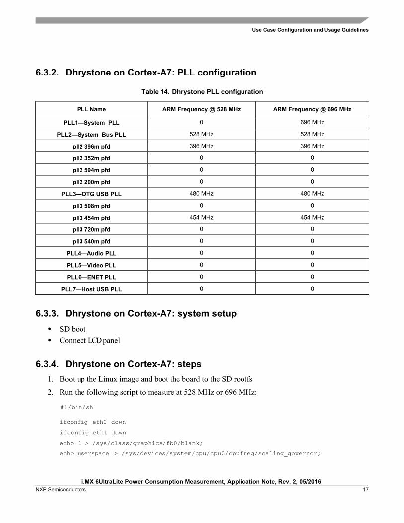
Table 1. VDDARM, VDDSOC voltage levels (for reference only)
ARM Frequency LDO State VDD_ARM_CAP VDD_SOC_CAP
696 MHz Enable 1.250 V 1.250 V
528 MHz Enable 1.150 V 1.150 V
396 MHz Enable 1.000 V 1.150 V
198 MHz Enable 0.925 V 1.150 V
Internal Power Measurement of the i.MX 6UltraLite Processor
3.4. Temperature measurements In some of the use cases the die temperature is measured. The temperature measurements were taken using the on-chip thermal sensor on a thermally calibrated part. While measuring temperature it is recommended to wait until the temperature stabilizes.
NOTE The measured temperatures are for reference only and will vary on different systems due to differences in board, enclosure, and heat spreading techniques. When using the same board type the measured temperature may vary due to factors such as environment, silicon variations, and measurement error.
3.5. Hardware and tool used The hardware and tool used for the measurements are as follows:
• The board used for the measurements is the MX6UL EVK Platform. • The measurements were performed using an Agilent 34401A 6½ Digit Multimeter.
3.6. Board setup used for power measurements The power measurements are taken using the default voltages of the supplies. The default input voltages are as follows:
• VDD_SOC_IN at 1.30 V for a maximum of 528 MHz ARM® frequency and at 1.4 V for a maximum of 696 MHz ARM frequency
• VDD_HIGH_IN at 3.3 V • NVCC_DRAM at 1.35 V
By using a different setup such as a configurable and separated DC switcher for ARM, the system power can be further optimized by reducing the VDD_SOC_IN input voltage level to achieve the desired operation point. Such a setup would likely result in a higher system cost, so there is a trade-off between cost and system power.
3.7. Measuring points on the MX6UL EVK platform The power data is obtained by measuring the average voltage drop over the measurement points and dividing it by the resistor value to determine the average current. The tolerance of the 0.02 Ω resistors on the EVK board is 1%. The measuring points for the various supply domains are as follows:
• VDD_SOC_IN: The chip domain current is measured on R729 and the recommended resistance value for this measurement is 0.02 Ω.
• VDD_HIGH_IN: The VDDHIGH domain current is measured on R732 and the recommended resistance value for this measurement is 0.02 Ω.
• DDR3L I/O plus Memories: The current in this domain includes the NVCC_DRAM current and
the overall current of the onboard DDR3L memory devices. The current in this domain is measured on R728 and the recommended resistance value for this measurement is 0.02 Ω.
4. Use Cases and Measurement Results The main use cases and subtypes, which form the benchmarks for the i.MX 6Ultralite internal power measurements on the EVK Platform, can be found the following sections.
4.1. Low-power mode use cases
4.1.1. Use case 1: Deep-Sleep mode (DSM) This mode is called either “Dormant mode” or “Suspend-To-RAM” in the Linux BSP. This is the lowest possible power state where external supplies are still on.
The use case is as follows: • ARM platform is power gated • L1 Cache periphery is power gated • SoC is in LDO bypass mode and ARM LDO is power gate automatically • All PLLs (phase locked loop) and CCM (clock controller module) generated clocks are off • CKIL (32 kHz) input is on • All of the modules are disabled • All analog PHYs are powered down • External high frequency crystal and on chip oscillator are powered down (by asserting SBYOS
bit in CCM) • VDD_SOC_IN is reduced to 0.925 V. In this mode, no current flow is caused by external
resistive loads.
The following table shows the measurement results when this use case is applied on the i.MX 6Ultralite processor.
Yocto release version: L4.1.15_1.1.1_6UL_GA_Patch; Linux Kernel Version: 4.1.15-1.1.1+gd5d7c02
P (mW) I (mA)
VDD_SOC_IN 0.923 0.2769 0.3
VDD_HIGH_IN 3.289 0.6578 0.2
Total Power (without DDR3L I/O + Memories) — 0.9347 —
DDR3L I/O + Memories 1.355 13.2113 9.75
Total Power — 14.146 —
For additional details on this use case and settings, see Section 6, Use Case Configuration and Usage Guidelines.
4.1.2. Use case two: system idle mode The use case is as follows:
• ARM is power gated if kernel is in the lowest level of idle • ANATOP will go into low power mode if lowest level of idle is entered and all PLLs are off • Operating system is on • LCD is turned off • Screen is not refreshed. This use cases simulates the situation when the device is left idle for
some time and the display is turned off after the timer expires.
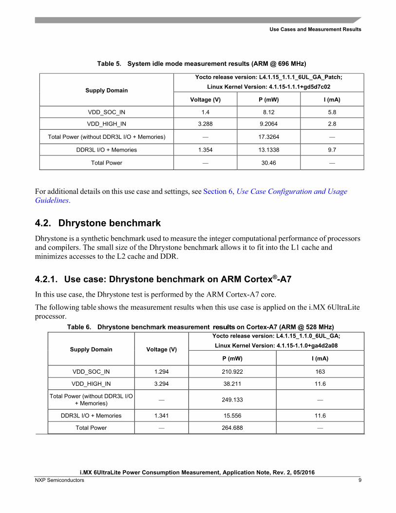
The following table shows the measurement results when this use case is applied on the i.MX 6UltraLite processor.
Yocto release version: L4.1.15_1.1.1_6UL_GA_Patch; Linux Kernel Version: 4.1.15-1.1.1+gd5d7c02
Voltage (V) P (mW) I (mA)
VDD_SOC_IN 1.4 8.12 5.8
VDD_HIGH_IN 3.288 9.2064 2.8
Total Power (without DDR3L I/O + Memories) — 17.3264 —
DDR3L I/O + Memories 1.354 13.1338 9.7
Total Power — 30.46 —
For additional details on this use case and settings, see Section 6, Use Case Configuration and Usage Guidelines.
4.2. Dhrystone benchmark Dhrystone is a synthetic benchmark used to measure the integer computational performance of processors and compilers. The small size of the Dhrystone benchmark allows it to fit into the L1 cache and minimizes accesses to the L2 cache and DDR.
4.2.1. Use case: Dhrystone benchmark on ARM Cortex®-A7 In this use case, the Dhrystone test is performed by the ARM Cortex-A7 core.
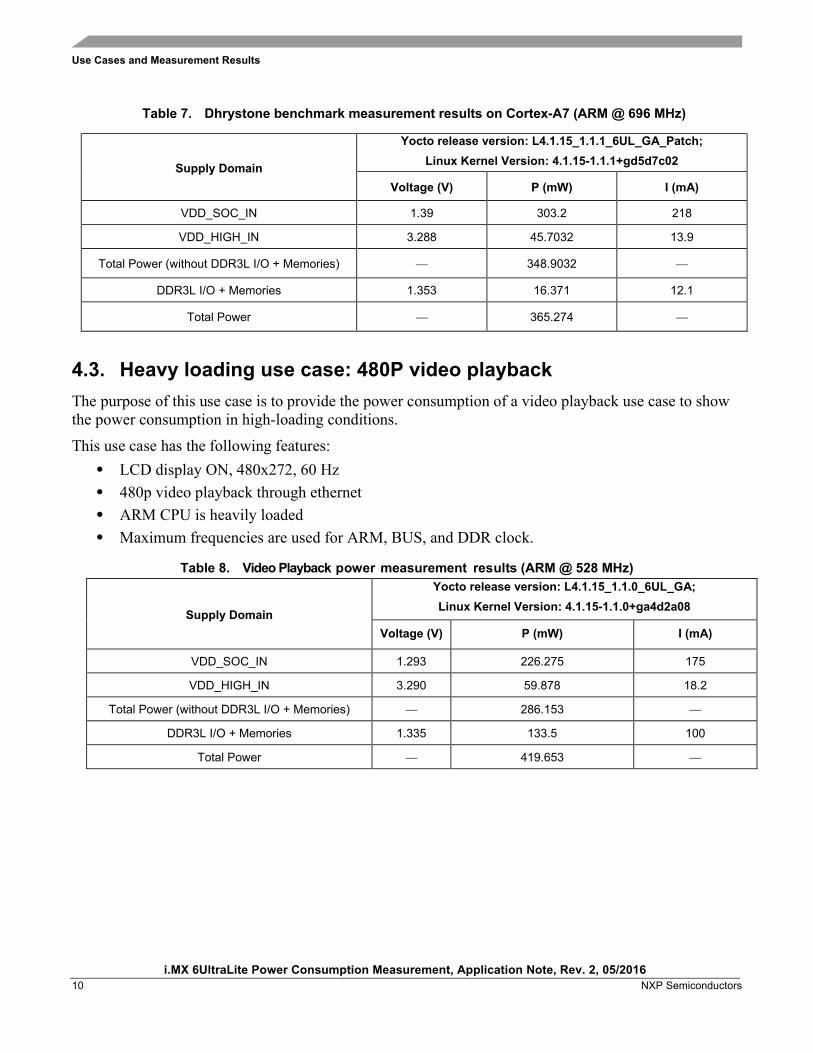
The following table shows the measurement results when this use case is applied on the i.MX 6UltraLite processor.
Yocto release version: L4.1.15_1.1.1_6UL_GA_Patch; Linux Kernel Version: 4.1.15-1.1.1+gd5d7c02
Voltage (V) P (mW) I (mA)
VDD_SOC_IN 1.39 303.2 218
VDD_HIGH_IN 3.288 45.7032 13.9
Total Power (without DDR3L I/O + Memories) — 348.9032 —
DDR3L I/O + Memories 1.353 16.371 12.1
Total Power — 365.274 —
4.3. Heavy loading use case: 480P video playback The purpose of this use case is to provide the power consumption of a video playback use case to show the power consumption in high-loading conditions.
This use case has the following features: • LCD display ON, 480x272, 60 Hz • 480p video playback through ethernet • ARM CPU is heavily loaded • Maximum frequencies are used for ARM, BUS, and DDR clock.
Table 8. Video Playback power measurement results (ARM @ 528 MHz)
Supply Domain
Yocto release version: L4.1.15_1.1.0_6UL_GA; Linux Kernel Version: 4.1.15-1.1.0+ga4d2a08
Voltage (V) P (mW) I (mA)
VDD_SOC_IN 1.293 226.275 175
VDD_HIGH_IN 3.290 59.878 18.2
Total Power (without DDR3L I/O + Memories) — 286.153 —
Table 9. Video Playback power measurement results (ARM @ 696 MHz)
Supply Domain
Yocto release version: L4.1.15_1.1.1_6UL_GA_Patch Linux Kernel Version: 4.1.15-1.1.1+gd5d7c02
Voltage (V) P (mW) I (mA)
VDD_SOC_IN 1.389 302.802 218
VDD_HIGH_IN 3.284 69.4566 21.15
Total Power (without DDR3L I/O + Memories) — 372.2586 —
DDR3L I/O + Memories 1.345 156.02 116
Total Power — 528.2786 —
4.4. SNVS In this use case, most of the power rails on the boards are off except from the VDD_SNVS domain. VDD_SNVS is kept on to ensure that RTC and other logic in the SNVS domain remain powered on. The following table shows the SNVS measurement results.
Table 10. SNVS measurement results
Supply Domain Voltage (V) Under SRTC mode, power consumption does not
depend on software
P (uW) I (uA)
VDD_SOC_IN 0 0 0
VDD_HIGH_IN 0 0 0
SNVS_IN 3.3 72.6 22
Total Power (without DDR3L I/O + Memories) — 72.6 —
NOTE The SNVS_IN power consumption in table 6 is measured according to the following conditions:
1. POR_B pin setting: GPBIT[1:0] set to 2b’01;
2. BOOT_MODE[1:0] switch to 2b'00 after system boot up;
3. Remove U2101.
Some recommendations can be considered for SNVS_IN power reduction: 1. "Boot From Fuses" as system BOOT TYPE which can remove the external resistors on BOOT_MODE0/1 PINs;
2. TAMPER0-9 PINs leave floating or only used as TAMPER function (only for MCIMX6G3Cxxxxxx);
3. Add isolation for TAMPER0-9 PINs if those are used as GPIO to prevent the SNVS_IN leakage.
SNVS_IN power design need to consider:
BOOT_MODE0/1, TAMPER0-9, POR_B those PINs connections.
5. Reducing Power Consumption The overall system power consumption depends on both software optimization and how the system hardware is implemented. Below is a list of suggestions that may help reduce system power. Some of these are already implemented in Linux BSP. Further optimizations can be done on the individual customer’s system.
NOTE Further power optimizations are planned for future BSP releases. See the NXP website to obtain the latest BSP release.
• Apply clock gating whenever clocks or modules are not used, by configuring CCGR registers in the Clock Controller Module (CCM).
• Reduce the number of operating PLLs: applicable mainly in Audio Playback mode or Idle modes.
• Core DVFS and system bus scaling: applying DVFS for ARM and scaling the frequencies of the AXI, AHB, and IPG bus clocks can significantly reduce the power consumption of the VDDARM and VDDSOC domains. However, due to the reduced operation frequency, the accesses to the DDR take longer, which increases the power consumption of the DDR I/O and memories. This trade-off needs to be taken into account for each mode, to quantify the overall effect on system power.
• Put the i.MX 6UltraLite into low-power modes (WAIT, STOP) whenever possible. See Chapter “Clock Controller Module (CCM)”of the i.MX 6Ultralite Applications Processor Reference Manual (document IMX6ULRM) for details.
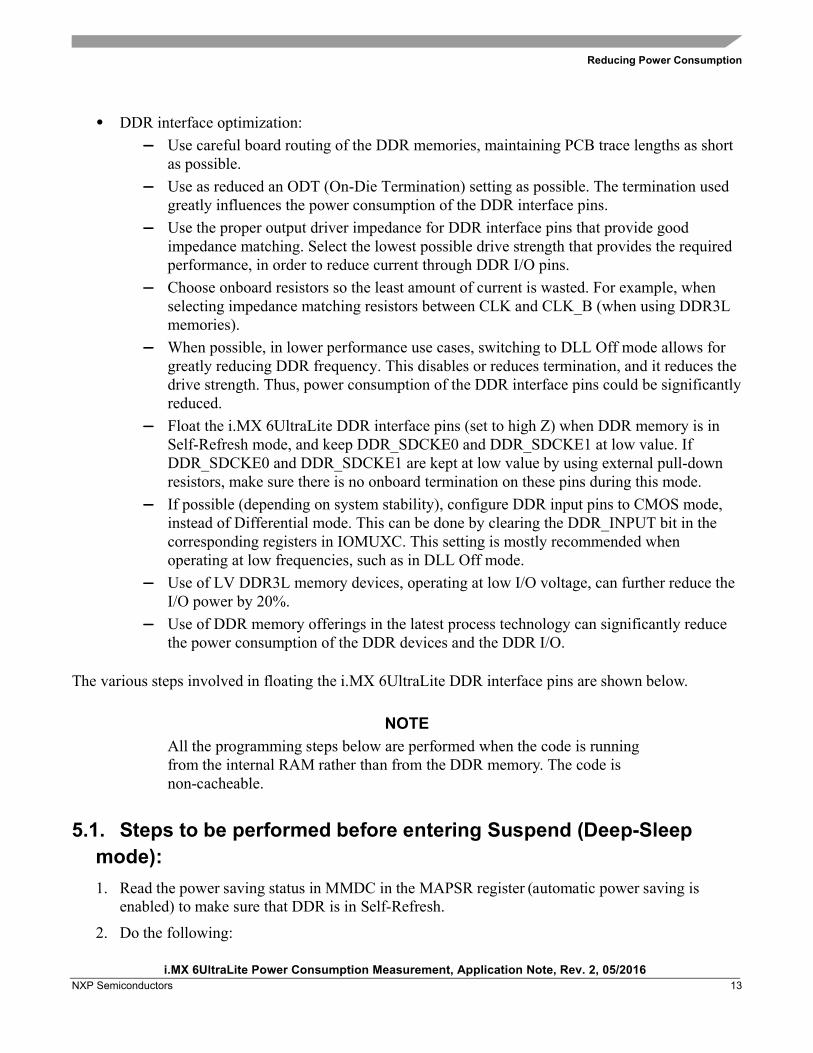
• DDR interface optimization: — Use careful board routing of the DDR memories, maintaining PCB trace lengths as short
as possible. — Use as reduced an ODT (On-Die Termination) setting as possible. The termination used
greatly influences the power consumption of the DDR interface pins. — Use the proper output driver impedance for DDR interface pins that provide good
impedance matching. Select the lowest possible drive strength that provides the required performance, in order to reduce current through DDR I/O pins.
— Choose onboard resistors so the least amount of current is wasted. For example, when selecting impedance matching resistors between CLK and CLK_B (when using DDR3L memories).
— When possible, in lower performance use cases, switching to DLL Off mode allows for greatly reducing DDR frequency. This disables or reduces termination, and it reduces the drive strength. Thus, power consumption of the DDR interface pins could be significantly reduced.
— Float the i.MX 6UltraLite DDR interface pins (set to high Z) when DDR memory is in Self-Refresh mode, and keep DDR_SDCKE0 and DDR_SDCKE1 at low value. If DDR_SDCKE0 and DDR_SDCKE1 are kept at low value by using external pull-down resistors, make sure there is no onboard termination on these pins during this mode.
— If possible (depending on system stability), configure DDR input pins to CMOS mode, instead of Differential mode. This can be done by clearing the DDR_INPUT bit in the corresponding registers in IOMUXC. This setting is mostly recommended when operating at low frequencies, such as in DLL Off mode.
— Use of LV DDR3L memory devices, operating at low I/O voltage, can further reduce the I/O power by 20%.
— Use of DDR memory offerings in the latest process technology can significantly reduce the power consumption of the DDR devices and the DDR I/O.
The various steps involved in floating the i.MX 6UltraLite DDR interface pins are shown below.
NOTE All the programming steps below are performed when the code is running from the internal RAM rather than from the DDR memory. The code is non-cacheable.
5.1. Steps to be performed before entering Suspend (Deep-Sleep mode): 1. Read the power saving status in MMDC in the MAPSR register (automatic power saving is
enabled) to make sure that DDR is in Self-Refresh.
a) If there is no onboard termination for DDR control and the address bus, set the DSE (drive strength selection, in IOMUXC) for all DDR IF I/O to 0 (High Z), except for CKE0 and CKE1.
b) If the DDR control and address bus have onboard termination resistors connected to VTT, such as in the case where SODIMM is used: o Option 1
As per 2a, keep SDCKE0/1 active, this causes some extra current from the pins sharing the same DSE control in IOMUXC_SW_PAD_CTL_GRP_CTLDS register. The pins are DRAM_CS0, DRAM_CS1, DRAM_SDBA2, DRAM_SDCKE0, DRAM_SDCKE1, and DRAM_SDWE.
o Option 2 (requires onboard pull down resistors on DRARM_SDCKE0/1 pins) Set the supply of the termination resistor to be floated (this can be done through
pins with GPIO capability). Set the DSE (drive strength selection, in IOMUXC) for all DDR IF I/O to 0 (High
Z).
3. Go into the Suspend mode.
5.2. Steps to be performed after exiting Suspend: 1. Restore all the settings for the DDR I/O to the required values.
2. The system proceeds to Run mode.
NOTE If the system can ensure there are no masters accessing the DDR, the following may be applied to other scenarios besides Deep-Sleep mode: DDR pins can be floated in the same manner, even when Suspend is not entered, and DDR can be manually put into Self-Refresh to save power. This happens when the CPU is not running, or it is running from the internal RAM.
6. Use Case Configuration and Usage Guidelines
6.1. Deep-Sleep mode In this use case all clocks and PLLs are turned off except the 32 kHz clock which is for system wake up.
1. Boot up Linux OS image.
2. Run below command to let system enter DSM mode: echo mem > /sys/power/state
2 05/2016 Updated 696 MHz data and related description
Document Number: AN5170 Rev. 2
05/2016
How to Reach Us:
Home Page: nxp.com
Web Support: nxp.com/support
Information in this document is provided solely to enable system and software implementers to use NXP products. There are no express or implied copyright licenses granted hereunder to design or fabricate any integrated circuits based on the information in this document. NXP reserves the right to make changes without further notice to any products herein.
NXP makes no warranty, representation, or guarantee regarding the suitability of its products for any particular purpose, nor does NXP assume any liability arising out of the application or use of any product or circuit, and specifically disclaims any and all liability, including without limitation consequential or incidental damages. “Typical” parameters that may be provided in NXP data sheets and/or specifications can and do vary in different applications, and actual performance may vary over time. All operating parameters, including “typicals,” must be validated for each customer application by customer’s technical experts. NXP does not convey any license under its patent rights nor the rights of others. NXP sells products pursuant to standard terms and conditions of sale, which can be found at the following address: nxp.com/SalesTermsandConditions
NXP, the NXP logo, NXP SECURE CONNECTIONS FOR A SMARTER WORLD, Freescale, the Freescale logo, and Kinetis are trademarks of NXP B.V. All other product or service names are the property of their respective owners.
ARM, the ARM Powered logo, and Cortex are registered trademarks of ARM Limited (or its subsidiaries) in the EU and/or elsewhere. All rights reserved.