Topics in.. . Chemical Instrumentation Edited by GALEN W. EWING, Seton Hall University, So. Orange, N. J. 07079 These articles are intended to serve the readers O~THIS JOURNAL by calling affenlion lo new developments i n the theory, design, or availability of chemical laboratory inslrumenlation, or by presenting useful insights and ez- planations of topics lhat are of practical importance to those who use, or leach /he use of, modern inslrumenlalion and inslrumental techniques. The editm inviles correspondence from prospective conlributors. LX. Step Perturbation Relaxation Techniques Icontinued, 2. A. Schelly, Department of Chemistry, The University of Georgia, Athens, Georgia 30601, and E. M. Eyring, Department of Chemistry, University of Utoh, Solt Lake City, Utah 841 12 Subsequent to same preliminary studies (34, 35) Erman and Hammes (36) de- veloped and successfully used a stopped- flow-T-jump apparatus, that led the Durrum Instrument Corporation to build a T-jump accessory for t,he Dmmm- Gibson stopped-flow instrument (37). The functioning of this apparatus can he described using Fignre 12. Charge is stored in a 1 pF capacitor C a t a potential V, variable from 2 to 5 kV. The capacitor is discharged through a spark gap that is triggered by an SCIL circuit. The dis- charge through t,he eell is initiated either permi& the choice of time delay Ah between mixing and discharge. The heat- ing current is terminated hy firing a second triggered spark gap that bypasses the cell and rapidly drains the condenser. This is usually called a crowbar (38). The heating-pulse width is determined by the time delay Atz between briggering the two spark gaps, controlled by a. delay n A,, I Figure 12. Schematic diogrom of the signal and control system of the Durrvm ,topped- Row-T-jump opporotus. iCourlesv Durrum) circuit adjustable from 5 to 100 psec. The function of the shorting switch is to sholt out all disturbing signals for a selecled time interval Ata following the firing of the second spark gap and then to present subsequent signal changes to the oscilloscope. The principle of the shorting circuit has been discussed by Cserlinski (10, 89). Figure 13 shows the photograph of the complete unit that can be used in the stopped flow or T-jump as well as in the combined mode. The stopped-flow part of the instrument is identical with that dexcribed in the fimt part of this nrticle, with the exception of the sample eell which is shown in Figure 14. The body and the electrode spacers are made of Kel-F and the electrodes, which are usually gold plated, of stainlesv steel. The windows are of quartz. Using this cell the instrument's mixing dead time is 10 msee. With a. sample resistance of 54 ohms, the voltage time ronstant is 54 psec and the heating time constant ro = 27 Fsec. Termination after 10 psec (triggering of the second spark gap) makes use of 31% of the stored energy. If initially the 1 FF condenser was charged up to T, kV, corresponding to 12.5 joules of stored energy, 311, of it (3.88 joules) can raise the temperature of 200 p1 (that is, the volume of the eell) of water by 4.63'C. The Pressure-Jump Method The dependence of the equilibrium concentrations on pressure is given by the function where AVO is the standard volume change for the reaction in question. If the reac- tion AVO is large enough (which is seldom feature Figure 13. The Durrum rtopped-flow-T-jump spectrophotometer. (Cowlow Duwum) the case) a. sudden 30-1.50 atmosphere jump of the pressure on a sample solution results in a chanee of eauilibrium con- - cent,rstions detectable with sensitive con- ductornetric techniques, and the rate of re-equilibration can be measured. A much improved version of the first pressure-jump apparatus of Ljunggren and Lrtmm (11) was developed by Streh- low and Becker (40) (Fig. 15). The jump of pressure is achieved by an abrupt depressurization of a previously pres- surized autoclave, in which the sample snd reference cells are located. The de- pressurisstion is initiated by puncturing a thin metal rupture disc by means of a solenoid-activated steel needle. The pres- sure in the autoclave initially of the order of 50-60 atmospheres drops to 1 atmas- phere within about 50 wet. The auto- clave (Fig. 16) is built of stainless steel. In order to minimize the apparatus relaxa- tion time (that is required by t,he eom- pressed gas to exhaust thmugh the mp- tured disc via a mufiler), the height of the pressurized gas layer, as well as the dis- tance between the bottom of the conduc- tivity cells and the Kel-F membrane are kept as small as possible. The solution under investigation is put into the minia- ture glass conductivity cell resting on a nylon base. The identical reference cell filled with a KNOs or KC1 solution pro- vides compensation for ihe temperature Figure 14. Cross section of the stopped-flow- T.iump cell. (Courlerv Durrum) (Continued on page A696) Volume 48, Number 1 I, November 1971 / A695
Transcript
Topics in.. . Chemical Instrumentation
Edited by GALEN W. EWING, Seton Hall University, So. Orange, N. J. 07079
These articles are intended to serve the readers O ~ T H I S JOURNAL by calling affenlion lo new developments i n the theory, design, or availability of chemical laboratory inslrumenlation, or by presenting useful insights and ez- planations of topics lhat are of practical importance to those who use, or leach /he use of, modern inslrumenlalion and inslrumental techniques. The editm inviles correspondence from prospective conlributors.
2. A. Schelly, Department of Chemistry, The University of Georgia, Athens, Georgia 30601, and E. M. Eyring, Department of Chemistry, University o f Utoh, Solt Lake City, Utah 841 12
Subsequent to same preliminary studies (34, 35) Erman and Hammes (36) de- veloped and successfully used a stopped- flow-T-jump apparatus, that led the Durrum Instrument Corporation to build a T-jump accessory for t,he Dmmm- Gibson stopped-flow instrument (37). The functioning of this apparatus can he described using Fignre 12. Charge is stored in a 1 pF capacitor C a t a potential V , variable from 2 to 5 kV. The capacitor is discharged through a spark gap that is triggered by an SCIL circuit. The dis- charge through t,he eell is initiated either
permi& the choice of time delay Ah between mixing and discharge. The heat- ing current is terminated hy firing a second triggered spark gap that bypasses the cell and rapidly drains the condenser. This is usually called a crowbar (38). The heating-pulse width is determined by the time delay Atz between briggering the two spark gaps, controlled by a. delay
n A , , I Figure 12. Schematic diogrom of the signal and control system of the Durrvm ,topped- Row-T-jump opporotus. iCourlesv Durrum)
circuit adjustable from 5 to 100 psec. The function of the shorting switch is to sholt out all disturbing signals for a selecled time interval Ata following the firing of the second spark gap and then to present subsequent signal changes to the oscilloscope. The principle of the shorting circuit has been discussed by Cserlinski (10, 89). Figure 13 shows the photograph of the complete unit that can be used in the stopped flow or T-jump as well as in the combined mode. The stopped-flow part of the instrument is identical with that dexcribed in the fimt part of this nrticle, with the exception of the sample eell which is shown in Figure 14. The body and the electrode spacers are made of Kel-F and the electrodes, which are usually gold plated, of stainlesv steel. The windows are of quartz. Using this cell the instrument's mixing dead time is 10 msee. With a. sample resistance of 54 ohms, the voltage time ronstant is 54 psec and the heating time constant ro = 27 Fsec. Termination after 10 psec (triggering of the second spark gap) makes use of 31% of the stored energy. If initially the 1 FF condenser was charged up to T, kV, corresponding to 12.5 joules of stored energy, 311, of i t (3.88 joules) can raise the temperature of 200 p1 (that is, the volume of the eell) of water by 4.63'C.
T h e Pressure-Jump Method
The dependence of the equilibrium concentrations on pressure is given by the function
where AVO is the standard volume change for the reaction in question. If the reac- tion AVO is large enough (which is seldom
feature
Figure 13. The Durrum rtopped-flow-T-jump spectrophotometer. (Cowlow Duwum)
the case) a. sudden 30-1.50 atmosphere jump of the pressure on a sample solution results in a chanee of eauilibrium con- - cent,rstions detectable with sensitive con- ductornetric techniques, and the rate of re-equilibration can be measured.
A much improved version of the first pressure-jump apparatus of Ljunggren and Lrtmm (11) was developed by Streh- low and Becker (40) (Fig. 15). The jump of pressure is achieved by an abrupt depressurization of a previously pres- surized autoclave, in which the sample snd reference cells are located. The de- pressurisstion is initiated by puncturing a thin metal rupture disc by means of a solenoid-activated steel needle. The pres- sure in the autoclave initially of the order of 50-60 atmospheres drops to 1 atmas- phere within about 50 wet. The auto- clave (Fig. 16) is built of stainless steel. In order to minimize the apparatus relaxa- tion time (that is required by t,he eom- pressed gas to exhaust thmugh the mp- tured disc via a mufiler), the height of the pressurized gas layer, as well as the dis- tance between the bottom of the conduc- tivity cells and the Kel-F membrane are kept as small as possible. The solution under investigation is put into the minia- ture glass conductivity cell resting on a nylon base. The identical reference cell filled with a KNOs or KC1 solution pro- vides compensation for ihe temperature
Figure 14. Cross section of the stopped-flow- T.iump cell. (Courlerv Durrum)
(Continued on page A696)
Volume 48, Number 1 I, November 1971 / A 6 9 5
Chemical Instrumentation
Figure 15. The pressure-jump appara tus (after Strehlow and W e n d t 141) and Takahashi ond Alberty 15511.
drop associnted with t,he adiabatic expan- sion of the solutimt and of the prcssore transmitting inert liquid (e.g., paraffin ail) that envelops the cells and solutions. The observation is startcd by the ti.i~ger- ing signal of n quarta prcssure transducer (e.g., Kistler No. 603, 01. eqnivalen0 that. senses the drop of presswe in the anta- clave. Constant tempet.ature is mnin- tained by thermostntitig coils noldel.ed to the nutorlavc. The plastic mnlller on the top of the nulorlave allertuates the luud report of the shork waves lo a tolerable level, and the capillary in the lead for the compressed ail. reduces the rate of air flow after the expwiment, thus protecting the manometer from x heavy shock.
Changcs of the roneentretiwls of reac- tants is followed nsiug conductivity measoremenls s t 3 frequency greater than the reciprocal of the shortest time rm- stant to he measmed (50-100 kHz). The conductivity cells in the autarlave A form two arms of an nc Whestslone bridge (Fig. 17) whose off-balance voltage is displayed on an oscilloscope OSC. Sinre stable bl.idge balance must be achieved to betler than I part in 10,000, the nc generator must have low hum, noise, and distortion ratings. Forthel.more, it is important that the oscillator 0 combined with the impedance matching t,rnnsformer Il' he free of overtones which is possihle only for bridge voltages less than 3 V (41 ). To reject any power line, broedcxsting, and high frequency noise R. filter P is inserted between the bl.idge xnd the preamplifier P. The triggering signal TS of the transducer amplified hy an amplifier A M P initiates the sweep of the oscillo- smpe. Pains must he taken to eliminate stray capacitanc-, thus extensive shield- ing of the components is necessary.
To our knowledge, no commercial P- jump apparatus is available, probably because of the inherent limitations of this technique. Chemical reactions are gener- ally less sensitive to feasible pressure changes than to temperature changes, therefore, the highest possible sensitivity is necessary to delect dinplscements of the equilibrium. This need for sensitivity has been the main reason for t,he use uf
(Continued on page Afi08)
A696 / Journal o f Chemical Education
Chemical Instrumentation
Figure 16. The autoclove (after Strehlow and Beeker 1401 and Takohoshi and Alberty 1551): (01 reference cell, (b) chemicol system in rompls cell, (c) pressure tronrmitting inert liquid, Id1 Kel-F membrane, lei transducer, If) air inlet lgl rupture dix, lhl to otcilloscope trigger, (;I to Wheotrtone bridge, l i ) thermostoting coils, ( k ) nylon gasket, (I) to air tank, (m) stainless steel autoclave body.
conductometric rather than spectrophoto- metric detection.
Other closely related methods of pro- ducing jumps using shack waves (@), standing sound waves (45), and eleetro- mechanical techniques (44) have been reported.
The Electric Field-Pulse Method
relation
where AD* is the difference of partial molar "polarization" of products and reactants (46). This means that if the reartiou iu question involves a net change in the mnmber of ions or a net change in the dipole moments, sn electric field can be used to perturb the system. Gener- ally, fields of the order of 50-100 kV/em mrmt be used to cause observable effects. If the system of interest is a week elec- trolyte, strong fields enhitnee dissociation. This is enlled the second Wien effect or dissociation-field effect. Onsager has
1
Figure 17. The Wheotrtone bridge (ofter Strehlaw and Wendt 141)).
(Continued on page A700)
given a theol.etical del.ivntkm of Lhis behavior based on detailed I<inetic cnleula- tious of ionic disweiatim and recombina- tion prarwses in a,, exlerml field (4 f i ) .
In the first eleelrir field jmnp (E-jump) experiment pe~.tu~.bnli,,n was caused by s s i ~ g l e strongly damped hannrmir il ill^- ti011 of tho electric field ( ) The applieatiun of a sin& ~ e e t a ~ ~ g d a r high voltage prdse to a clmniral syslcm, first, accomplished by Eigm rind I)o\lnoyor
Voltoqe measurement
l and tugger
Figure 18. Schematic diagram of o high-voltage square-puke generator (after Eigen and DeMoeyel 1211.
A700 / Journol of Chemicol Educofion
Figure 19. Wheaktotono bridge arrangement for high field pulse meorvrernenk (after Eigen and DeMoeyerl211.
stone bridge. The square pulse is pra- duced in the fallowing way: A high voltage generator charges condenser C- (0.15 pF) through a load resistor (30 Ma) to the required potential (20-100 kV) preset on the voltage measurement and trigger unit. At the desired voltage spark gap I is triggered and the voltage- jump with a very short rise time (below 0.1 psec) k applied to the Wheatstone bridge consisting of the sample R. and reference R, cells, as well ss the lo3 times smaller ramparison resistances (or cells) I& and R The bridge design follows the crossshaped pattern of Figure 19. The coaxial construction and perpendic- ular set up of the components together with a well shielded container avoid dissymmetrical stray capacitances and mutual inductive coupling between the bridge arms, which could degrade the square pulse. R. and R, must be large enough so that during the time until the firing of the second spark gap I1 the voltage across them stays practically constant. This can be achieved by work- ing a t low ionic concentrations and in solvents with essentially no ion impurities. To compensate for the several secondary effects of the high field such as (a) changes in conductivity owing to disturbance of the ionic atmosphere, called the first Wien effect, ( b ) unavoidable Joule heating of a few hundredths of a degree, (c) electrode polarization, (d ) space charge effects, ( e ) pressure rise due to the isochoric field change, no absolute, but rather a differ- ence measurement of the conductivity is used. For this purpose the reference cell iz filled with a solution of strong elec- trolyte of the same rnnductivity, and with ionic mobilities similar to those in the solut,ion under study
oil for thermostoling, 7 Plexiglas container.
I Figure 20. Construction of the sample cell Ifram Eigen ond DeMaeyer 14811: 1 gloss cell, 2 blank platinum electrodes, 3 outer shield, 4 high voltage leads, 5 insulation, 6 transformer
(Continued on page A70k)
A702 / lourno1 of Chemical Education
Chemical Insrrumentation
Figure 21. Schematic diagram of a coaxial cable discharge arrangement to produce high- voltage rectangular pulses of short ritetime and duration, and optical arrangement to observe concentration changes during application of the pulse to a weak electrolyte rolution. The co- axial sable A-B i s 300 m long. I t is charged via a I 0 0 0 Megohm resistor connected to point C. The voltage ot the inner conductor i 3 con- nected to the obrervation cell R M via o small damping ond protection resistor Rs when the first spark gap 51 flyer. This triggers the firing of spa* gap R ofter o variable delay. Between points B and C a 5 0 ohm resistor i s provided to terminate the cable in a matched lood when Sz Ores (from DeMoeyer 15211.
After afew microseconds of delay, while the first gap is still in a rondocting stnle, the second spark gap I1 is triggered, shorting the bridge and tho condenser to gwnnd. The high field on the cell suddellly collapses. Small damping resis- tances are built into the circuit to prevent high frequency oscillations after firing the spark gaps.
The fnnction of t,hc volt,age measwe- ment and cont,rol unit is t,o mensure the voltage on the condenser by rnenlrs of a vac~uln-tube voltmeter and to prodtlco the triggering p~dses. T~.iggering orrow based on the indication of the vvllincte~. through x comparator circuit,. The I t + -
ger pulses are delayed by monmlnhle mrdtivibrators.
The coastruet,ion of the sample cell is shown in Fignre 20 with the electndes 5 mm apart.
To achieve a short,er rise time of the square pnlse (the order of a few ~ixrio- seconds) othet. invest,ignt,orn nsed rasrinl- cable dischxr~es (48-51). Pigwe 21 shows 1lgenfl.ibs's eqnipment (411) with spectmphotornetrie detection, and Figire 22 shows the sample cell he raed. The advantage af optical monitoring of the renctiou is that the back rolasal.ion in zero field can also he observed. This is no1 possible with condnct,ivit,y deteriiuu, since the measwing voltage in a b r i d ~ e arrangement is zero when the field is olT st the end of the pnlse. Thc ohservn- tion of l.ho relaxation in zero Aeld is pnr- ticdnrly desirable since Ihere is then no degradation of the signal by Jvrde henling.
Tu eliminate pmblems nssorinierl with the me of several hondred meters of coaxial delay cables (48-521 xrr inslrnmetrt was recently developed (53) which p1.0- durcs a single 30-52 kV high valbnge squxre pulse of 0 tb 28 psec duration with rise a d fall time of less than 22 nsec. I t uses s. low inrluetance 0.00.5 pF 60 kV plsslio capacitor with t,riggered spark gaps to init,iate and terminnt,e the pnlse a t times determined by solid stnie oil.- cnitry and high thveslrold logic. llilrging of the leading and trailing edges of t,he
(Conl ind on page A708)
A704 / Journal of Chemical Education
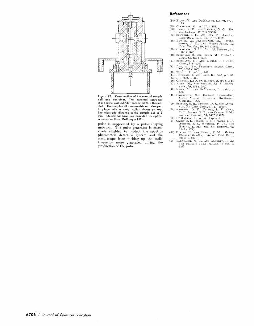
Figure 22. Crorr section of the cooxiol rample cell and container. The external container i s o double-woll cylinder connected to a thermo- stat. The sample cell ir removable and in place with o metal collar shown on top. The electrode dirtonce in the sample cell is 5 mm. Quartz window ore provided for opt icd observation lfrom DeMoeyer (521).
pulse is suppressed by 8. p d s e shaping network. The pulse generator is exten- sively shielded to protect the speetro- photometric detection system and the oscilloscope from picking up the radio frequency noise generated during the production of the pulse.
References
(34) EIBEN. M.. AND D E M A E ~ R . L.: ref. 17. p. 175.
(35) C z ~ n ~ m s n r , G.: ref. 17, p. 183. (36) Enwm. J. E., nwo H.WMES, G. G.: Rei..
Sli. In8lium.. 37, 710 (1065). (371 S~r.w*n~. J. E.. AND LUM, P.: Americm
STOIB. J. N.. ~ v o ~ V Y N P E . , J D N ~ ~ . I,.: Disc. Poi. Soc., 39, 149 11965).
(39) C z ~ n ~ r ~ m r . G. H.: Rev. Sci . J n s ~ u m . , 39, 171" I I O R P > ~... "",.
(40) Smzamv. H.. AWD nrcazn. M.: Z. Ele l t~o- chem.. 63. 457 (1959).
(41) S ~ n r n ~ o - , H., AND ~ Y E N D T . H.: Inorg. Chem.. 2 , 6 (1962).
(42) .ros.r. n.: E S T . B U ~ ~ W ~ ~ . ~ n ~ i k . cham.. 70, 1057 (1966).
(43) 1Vmor'. H.: B i d . , p . 555. (44) H o F " ~ , . ~ , H.. AND PA",,,. K . : ibid. . P. 1052. (45) of. Ref. 2. p. 930. (46) O ~ s n o ~ n . L.: J . Chem. Phyr . , 2 , 599 (1934). (47) EIGEN. 3%. AND SCIIOEN, J.: Z. Eleftra-
chem.. 59, 483 (1955). (48) E1aEN, nx., ,,m n ~ f i ~ ~ . , , L. : ;bid.. ..
Q%6 (49) I~~OEXFRITZ, G.: Doot~ra l D i ~ ~ e r t ~ t i o n .
Georg August University, Goettinqen. Germany, 1966.
(50) STAPLIS, 1%. R., TURNER, D. J.. m n ATKIN- sos, G . : Chem.Jnsli . . 2 , 127 (1969).
(51) RAWTOW, D. T., HOLYES. L. P.. Corn, U. L., JELISZN. R. P.. AND E Y R l h - 0 , E. M.: Re". Sci. Jnolium.. 38, 1637 (19671.
(52) DEMISYER, L.: ref. 5. chapter 4. (53) OLSEB, S. L., SILVER. R. L., HOLMPA L. P.,
A u n a n ~ . J. J.. 1v*nnrcr. P.. JR.. *No
1247 (1971). (54) Eunrxo, A,. AND Emma. E. M.: Modern
Chemical Kinetics. Reinhold Publ. Corn., 1966: P. 97.
(55) T * n n m r ~ ~ , M. T.. AND A L ~ E B T Y , R. A,: The Pressure J u m p Method, in rei. 5. %Iff.