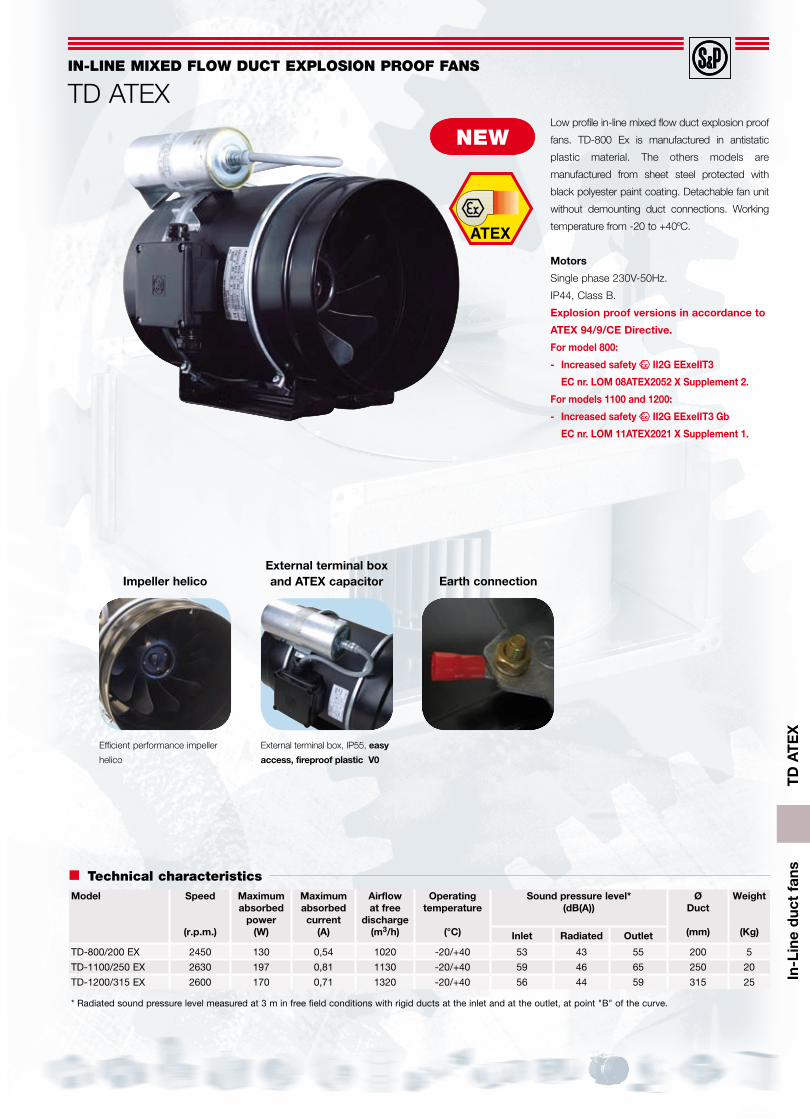
TD ATEX In-Line duct fans Low profile in-line mixed flow duct explosion proof fans. TD-800 Ex is manufactured in antistatic plastic material. The others models are manufactured from sheet steel protected with black polyester paint coating. Detachable fan unit without demounting duct connections. Working temperature from -20 to +40ºC. Motors Single phase 230V-50Hz. IP44, Class B. Explosion proof versions in accordance to ATEX 94/9/CE Directive. For model 800: - Increased safety II2G EExeIIT3 EC nr. LOM 08ATEX2052 X Supplement 2. For models 1100 and 1200: - Increased safety II2G EExeIIT3 Gb EC nr. LOM 11ATEX2021 X Supplement 1. Model Speed (r.p.m.) Maximum absorbed power (W) Maximum absorbed current (A) Airflow at free discharge (m 3 /h) Operating temperature (°C) Sound pressure level* (dB(A)) Ø Duct (mm) Weight (Kg) Inlet Radiated Outlet TD-800/200 EX 2450 130 0,54 1020 -20/+40 53 43 55 200 5 TD-1100/250 EX 2630 197 0,81 1130 -20/+40 59 46 65 250 20 TD-1200/315 EX 2600 170 0,71 1320 -20/+40 56 44 59 315 25 * Radiated sound pressure level measured at 3 m in free field conditions with rigid ducts at the inlet and at the outlet, at point "B" of the curve. IN-LINE MIXED FLOW DUCT EXPLOSION PROOF FANS TD ATEX Technical characteristics Impeller helico External terminal box, IP55, easy access, fireproof plastic V0 External terminal box and ATEX capacitor Earth connection Efficient performance impeller helico NEW
* Radiated sound pressure level measured at 3 m in free field conditions with rigid ducts at the inlet and at the outlet, at point "B" of the curve.
IN-LINE MIXED FLOW DUCT EXpLOsION prOOF FANs
TD ATEX
Technical characteristics
Impeller helico
External terminal box, IP55, easy
access, fireproof plastic V0
External terminal box and ATEX capacitor Earth connection
Efficient performance impeller
helico
NEW
TD
AT
EX
In-L
ine
duc
t fa
ns
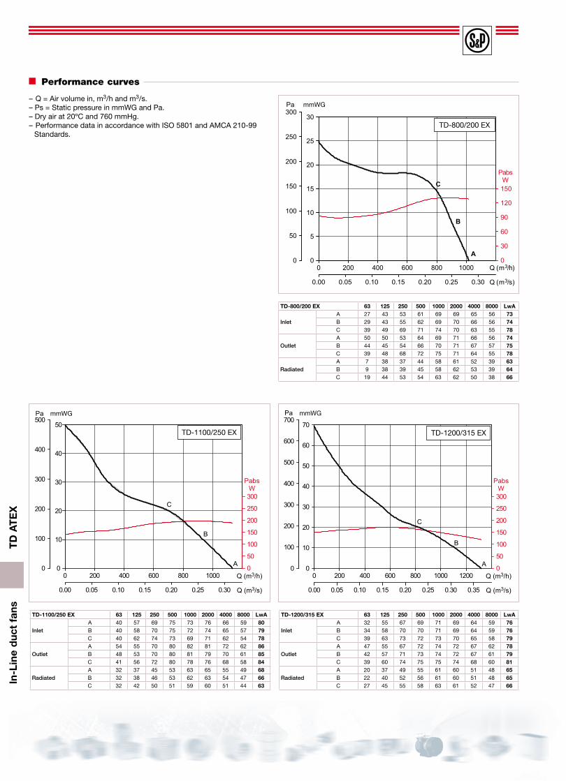
performance curves
– Q = Air volume in, m3/h and m3/s.– Ps = Static pressure in mmWG and Pa.– Dry air at 20ºC and 760 mmHg.– Performance data in accordance with ISO 5801 and AMCA 210-99