TD-SILENT In-Line duct fans Low profile “Mixed-flow” fans with sound-ab- sorbent insulation. Extremely quiet. Manufactured in plastic material, with a specifi- cally designed internal skin to direct the sound waves in the right angle for them to be captured by the sound-absorbent material (1).Fitted with rubber gaskets on the inlet and outlet to absorb vibrations, a body that can be dismantled. Connection box can be rotated 360º, to facilitate easy connection of the power cable. Motors Speed controlable 230 V 50 Hz motor, of two speed motors. Motors are IP44, class B, with ball bearings and safety thermal overload protection. (1) Except the TD-160 SILENT, that is fitted with the special floating motor system patented by S&P. IN-LINE MIXED FLOW DUCT FANS ULTRA-QUIET TD-SILENT Series (160 to 1000 models) Low profile “Mixed-flow” fans with sound- absorbent insulation. Extremely quiet. Constructed from sheet steel with epoxy polyester paint, acoustic insulation (MO) glass fibre, within outer shell. Aerodynamic inlet to improve air flow and reduce sound. Detachable fan unit without demounting duct connections. External terminal box IP55. Removeable fan body with 2 speed motor, single phase 230V-50/60Hz speed controlable, IP44, Class F, external rota aluminium motor with capacitor and thermal protection. Additional information The models offer solutions to ventilation problems, especially in places where people work and low sound level is required. TD-SILENT Series (1300 and 2000 models) NEW
Transcript
TD
-SIL
EN
TIn
-Lin
e d
uct
fans
Low profile “Mixed-flow” fans with sound-ab-
sorbent insulation. Extremely quiet.
Manufactured in plastic material, with a specifi-
cally designed internal skin to direct the sound
waves in the right angle for them to be captured
by the sound-absorbent material (1).Fitted with
rubber gaskets on the inlet and outlet to absorb
vibrations, a body that can be dismantled.
Connection box can be rotated 360º, to facilitate
easy connection of the power cable.
Motors
Speed controlable 230 V 50 Hz motor, of two
speed motors.
Motors are IP44, class B, with ball bearings and
safety thermal overload protection.
(1) Except the TD-160 SILENT, that is fitted with the special
floating motor system patented by S&P.
IN-LINE MIXED FLOW DUCT FANS ULTrA-qUIET
TD-SILENT Series(160 to 1000 models)
Low profile “Mixed-flow” fans with sound-
absorbent insulation. Extremely quiet.
Constructed from sheet steel with epoxy
polyester paint, acoustic insulation (MO)
glass fibre, within outer shell.
Aerodynamic inlet to improve air flow and reduce
sound.
Detachable fan unit without demounting duct
connections.
External terminal box IP55.
Removeable fan body with 2 speed motor,
single phase 230V-50/60Hz speed controlable,
IP44, Class F, external rota aluminium motor
with capacitor and thermal protection.
Additional information
The models offer solutions to ventilation problems,
especially in places where people work and low
sound level is required.
TD-SILENT Series(1300 and 2000 models)
NEW
TD
-SIL
EN
TIn
-Lin
e d
uct
fans
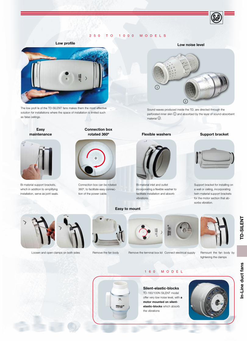
Easy maintenance
Bi-material support brackets,
which in addition to simplifying
installation, serve as joint seals.
Connection box rotated 360º
Connection box can be rotated
360º, to facilitate easy connec-
tion of the power cable.
Flexible washers
Bi-material inlet and outlet
incorporating a flexible washer to
facilitate installation and absorb
vibrations.
Support bracket
Support bracket for installing on
a wall or ceiling, incorporating
twin-material support brackets
for the motor section that ab-
sorbs vibration.
Low profile
The low profi le of the TD-SILENT fans makes them the most effective
solution for installations where the space of installation is limited such
as false ceilings.
2 5 0 t o 1 0 0 0 m o d e l s
Low noise level
Sound waves produced inside the TD, are directed through the
perforated inner skin 1 and absorbed by the layer of sound-absorbent
material 2 .
1
2
Remove the fan body Connect electrical supply Remount the fan body by
tightening the clamps
Remove the terminal box lidLoosen and open clamps on both sides
Easy to mount
1 6 0 m o d e l
Silent-elastic-blocks TD-160/100N SILENT model
offer very low noise level, with a
motor mounted on silent-
elastic-blocks which absorb
the vibrations
TD
-SIL
EN
TIn
-Lin
e d
uct
fans
Easy maintenance
Detachable fan unit for maintenance, or cleaning, without demounting
duct connections.
Support bracket
Suitable for wall or ceiling
mounting. Fixing brackets to the
motor-body included.
Low profile - compact
Low profile fans TD-1300/250 SILENT and TD-2000/315 SILENT are
ideal for installations where space is very small, as in false ceilings.
1 3 0 0 a n d 2 0 0 0 m o d e l s
Acoustic insulation (MO) glass fibre
Outer shell
Aerodynamic inlet to improve air flow and reduce sound
Attenuating perforated skin4
3
1
2
IP55 remote terminal box
Easy installation and connection.
Low noise level
3
4
1
2
TD
-SIL
EN
TIn
-Lin
e d
uct
fans
Model Nom. speed
(r.p.m.)
Maximumabsorbed
power (W)
Maximumabsorbedcurrent
(A)
Duty at freedischarge
(m3/h)
Maximumoperating
temp.(ºC)
Soundpressure
level*(dB(A))
Ø Duct
(mm)
Weight
(Kg)
TD-160/100 N SILENT25002200
2512
0,16 0,10
180 140
-20/+402421
100 1,40
TD-250/100 SILENT22001850
2418
0,11 0,10
240 180
-20/+402419
100 5,40
TD-350/125 SILENT22501900
3022
0,13 0,10
380 280
-20/+402019
125 4,94
TD-500/150-160 SILENT **25001950
5044
0,22 0,19
580 430
-20/+602217
150 /160 6,00
TD-800/200 SILENT27802480
9590
0,450,43
880700
-20/+601918
200 8,70
TD-1000/200 SILENT25002000
120100
0,500,45
1100800
-40/+602120
200 8,70
td-1300/250 sIlent25702190
197145
0,830,61
12701070
-40/+603531
250 20,0
td-2000/315 sIlent26802300
297191
1,280,79
17701500
-40/+603933
315 25,0
* Sound pressure level radiated at 3 m at free air conditions with rigid ducts at the inlet and at the outlet.** It provides an additional rubber gasket for installation in 160 mm ducts.
Technical characteristics
TD
-SIL
EN
TIn
-Lin
e d
uct
fans
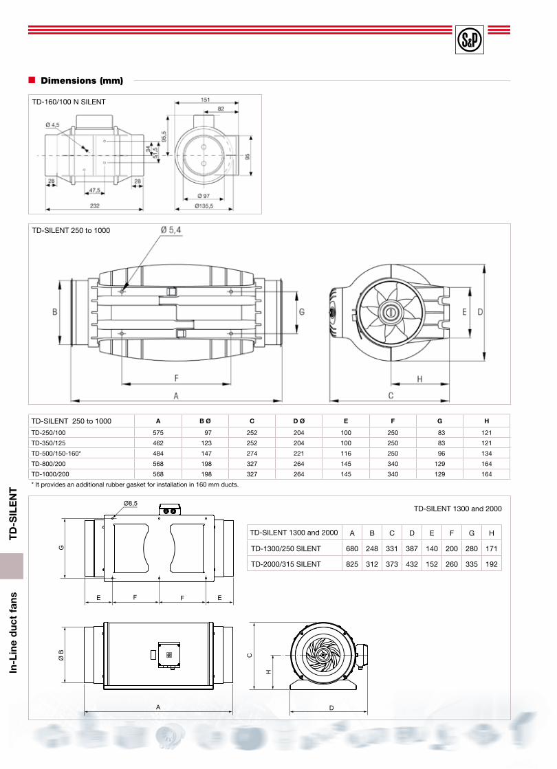
Dimensions (mm)
TD-SILENT 250 to 1000 A B Ø C D Ø E F G H
TD-250/100 575 97 252 204 100 250 83 121
TD-350/125 462 123 252 204 100 250 83 121
TD-500/150-160* 484 147 274 221 116 250 96 134
TD-800/200 568 198 327 264 145 340 129 164
TD-1000/200 568 198 327 264 145 340 129 164
* It provides an additional rubber gasket for installation in 160 mm ducts.
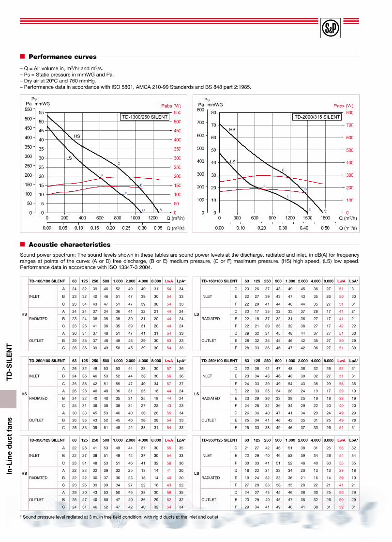
– Q = Air volume in, m3/hr and m3/s.– Ps = Static pressure in mmWG and Pa.– Dry air at 20ºC and 760 mmHg.– Performance data in accordance with ISO 5801, AMCA 210-99 Standards and BS 848 part 2:1985.
Sound power spectrum: The sound levels shown in these tables are sound power levels at the discharge, radiated and inlet, in dB(A) for frequency ranges at points of the curve: (A or D) free discharge, (B or E) medium pressure, (C or F) maximum pressure. (HS) high speed, (LS) low speed. Performance data in accordance with ISO 13347-3 2004.
* Sound pressure level radiated at 3 m. in free field condition, with rigid ducts at the inlet and outlet.
Performance curves
– Q = Air volume in, m3/hr and m3/s.– Ps = Static pressure in mmWG and Pa.– Dry air at 20ºC and 760 mmHg.– Performance data in accordance with ISO 5801, AMCA 210-99 Standards and BS 848 part 2:1985.
* Sound pressure level radiated at 3 m. in free field condition, with rigid ducts at the inlet and outlet.
Acoustic characteristics
Sound power spectrum: The sound levels shown in these tables are sound power levels at the discharge, radiated and inlet, in dB(A) for frequency ranges at points of the curve: (A or D) free discharge, (B or E) medium pressure, (C or F) maximum pressure. VR, fast speed. VL, slow speed. Performance data in accordance with ISO 13347-3 2004.
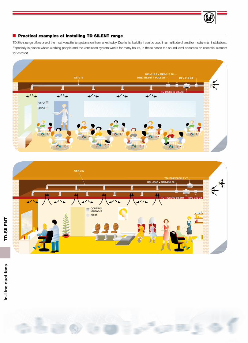
TD Silent range offers one of the most versatile fansystems on the market today. Due to its flexibility it can be used in a multitude of small or medium fan installations.
Especially in places where working people and the ventilation system works for many hours, in these cases the sound level becomes an essential element
for comfort.
TD
-SIL
EN
TIn
-Lin
e d
uct
fans
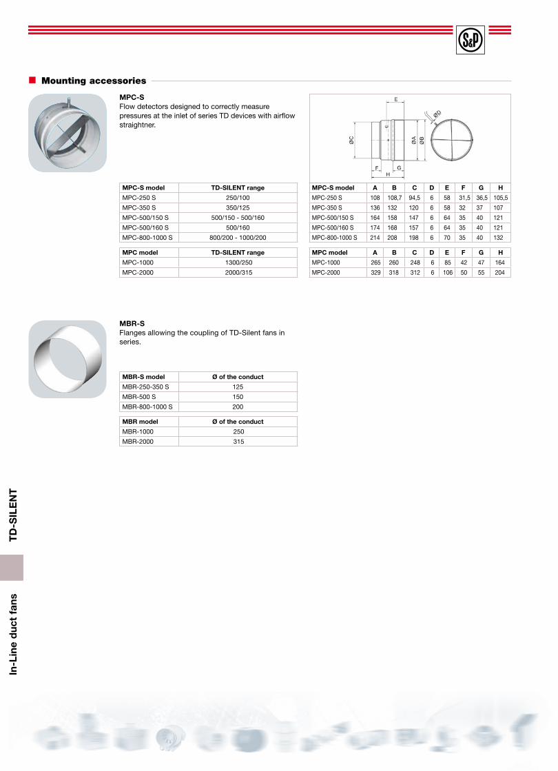
Mounting accessories
D
C
B
A
MCA-SNon-return flaps to be installed at the fan discharge.They prevent heat leakages when the extractor is not operating.
A
F
ø G
E B
C
MAR-SRectangular Duct Adapters enable connection to rectangular ducting.
MAR-S model TD-SILENTrange
Nominal dimensionsof the duct L x H
MAR - 250 - 350-S 160/100N - 250/100 - 350/125 224 x 140
MAR - 500-S 500/150 280 x 180
MAR - 800 - 1000-S 800/200-1000/200 315 x 200
MAR-S model A B C E F Ø G
MAR - 250-350-S 264 180 33,3 160 244 9
MAR - 500-S 320 220 37 200 300 9
MAR - 800 -1000-S 355 240 37 220 335 9
MRJ-SGrilles mounted at the inlet or outlet of the fan, to prevent the entry of any foreign objects that could damage the fan.
MRJ-S model TD-SILENT range
MRJ - 250 - 350-S 160/100N - 250/100 - 350/125
MRJ - 500/150 - 160-S 500/150 - 500/160
MRJ - 800 - 1000-S 800/200 - 1000/200
MCA-S model A Ø B C Ø D
MCA - 250 S 107 109 31,5 94,5
MCA - 350 S 107 136 31,5 119,5
MCA - 500/150 S 121 163,5 35 147
MCA - 500/160 S 121 173,5 35 157
MCA - 800-1000 S 131,5 214 35 197,5
MCA-S model TD-SILENT range
MCA - 250 S 160/100N - 250/100
MCA - 350 S 350/125
MCA - 500/150 S 500/150
MCA - 500/160 S 500/160
MCA - 800-1000 S 800/200 - 1000/200
MCA model A Ø B C Ø D
MCA - 1000 164 264,5 42 248
MCA - 2000 205 330 50 312
MCA model TD-SILENT range
MCA - 1000 1300/250
MCA - 2000 2000/315
MAR model A B C E F Ø G
MAR - 1000 440 290 42 270 420 9
MAR - 2000 540 355 52 355 520 9
MAR model TD-SILENTrange
Nominal dimensions of the duct L x H
MAR - 1000 1300/250 400 x 250
MAR - 2000 2000/315 500 x 315
MRJ model TD-SILENT range
MRJ - 1000 1300/250
MRJ - 2000 2000/315
TD
-SIL
EN
TIn
-Lin
e d
uct
fans
MBR-SFlanges allowing the coupling of TD-Silent fans in series.
MBR-S model Ø of the conduct
MBR-250-350 S 125
MBR-500 S 150
MBR-800-1000 S 200
MPC-SFlow detectors designed to correctly measure pressures at the inlet of series TD devices with airflow straightner.
MPC-S model A B C D E F G H
MPC-250 S 108 108,7 94,5 6 58 31,5 36,5 105,5
MPC-350 S 136 132 120 6 58 32 37 107
MPC-500/150 S 164 158 147 6 64 35 40 121
MPC-500/160 S 174 168 157 6 64 35 40 121
MPC-800-1000 S 214 208 198 6 70 35 40 132
MPC-S model TD-SILENT range
MPC-250 S 250/100
MPC-350 S 350/125
MPC-500/150 S 500/150 - 500/160
MPC-500/160 S 500/160
MPC-800-1000 S 800/200 - 1000/200
MPC model A B C D E F G H
MPC-1000 265 260 248 6 85 42 47 164
MPC-2000 329 318 312 6 106 50 55 204
MPC model TD-SILENT range
MPC-1000 1300/250
MPC-2000 2000/315
MBR model Ø of the conduct
MBR-1000 250
MBR-2000 315
Mounting accessories
TD
-SIL
EN
TIn
-Lin
e d
uct
fans
Electrical accessories
REGUL 22 speed switch.
REBSingle phase electronic speedcontroller.
CONTROL ECOWATT AC/4AControl element for demand controlled ventilation systems in public, commer-cial residential buildings that automatically modifies the fan speed to adapt it to the needs defined in the system, measured with sensors.
VAPZElectronic single phase regulator that controls the fan speed with a simple contact (presence detector) or an analogical input, 0-10 V or 4-20 mA (C02 probe for relative humidity % RH).
SCO2-AAmbient C02 and temperature sensor.SCO2-ADAmbient C02 and temperature sensor, with display.SCHT-ADAmbient C02 ,temperature and relative humidity with display.
CPFL-S / CPFL-EPresence detector for wall fitting, sensi-tive to infrared radiation by bodies in movement, with a 360º detecting angle. Power supply:1-230 V.
TDP-S / TDP-DPresure sensor. Enables you to control the pressure in the fan inlet.Presure range: 0-2500 Pa.Output signal: 0-10V/4-20 mA.
REMPMotorised damper, opening proportionally and controlled by the BEAS control module.Power supply: 24 VAC or 24 VD, depending on the models.