PROCEEDINGS OF THE IRE In-Service Improvements 'in Air 'Irafflc (ontrol* P. T. ASTHOLZt, SENIOR MEMBER, IRE Summary-This paper covers several of the significant "in- service improvements," including the introduction of simulation study techniques, new displays, and automatic data processing that have been taken to meet the air traffic control requirements. A review of the three basic simtulation methods: graphical, dynamic, and fast time is provided together with a description of the dynamic simula- tion facilities at the Technical Development Center of the Federal Aviation Agency (FAA), Indianapolis, Ind. The requirements for day- light viewing displays and the programns conducted to obtain TV types of radar displays are included. The report concludes with the introduction of digital computers to perform certain data processing functions. INTRODUCTION STEADY, but niot widely kniown, improvement in air traffic control has been obtained by the Civil Aeronautics Administration (now the Fed- eral Aviation Agency as of December 31, 1958) through the introduction of certain new study techniques, new equipments, and new procedures in an attempt to keep pace with the growing air traffic and the user require- ments. While certain major and long-range steps are required, and programs to accomplish them have been introduced by the Airways M\lodernization Boaid and the niew Federal Aviation Agency, it is believed that some of the day-to-day steps sometimes called "in-serv ice improvements" are of interest. In the final report by the President's special assistant, referred to as the Cur tis Report,i a three-part program for meeting the iia- tion's future needs was outlined. This prograni, as sum-, marized in the report, was as follows: Phase I-lImmnediate steps to augment anid itm- prove the current plans of the Civil Aeronautics Administration. Phase 1[II mmediate establishment and execution of a unified modern research and devel- opmenit program, addressed principally to early application of existing scientific technology, Phase 1III-Establishment of a permanent program of continuing modernization of the ua- tion's aviationi facilities. The in-service improvements are now generally called Phase I of this program although some overlapping inito Phase 1I is apparent. The safety and capacity of the air traffic control (ATC) system have been increased with the implementation of a two-way VHF and UHF com- niunication system between the pilot and controller, * Originial maniuscript received by the IRE, December 2, 1958; revised manuscript received, February 6, 1959. t Tech. Dev. Center, Fed. Aviation Agcy., Indianapolis, Ind. E. P. Curtis, "Aviation Facilities Planning, Final Report by the President's Special Assistant," Supt. of Documents, Goxvt Pritnitng Office, AVashington, D. C.; MavT, 1957. with the VOR'JTAC navigatior system, anid with reor ganization of the airway system. This paper covers sev- eral of the other significant improvements, including the use of simulation techiiiques to study basic ATIC characteristics, improved radar displays, and introduc tion of digital conmputers for semiautomatic data proc essinlg, SIM ULATION In order to obtain a firmer grasp of a problemi area, it is important to understand the basic characteristics and functions, together with the requiremiients involved. 11' possible, a mathemnatical model of the system is created to aid in defining the parts of the system. In humani machine relationships, such as those erncountered in air traffic conitrol, it is difficult to describe certain- parts of the systemi in imathematical terms. As a result, simula tion techniques are being used as a study tool to provide estimates of the level of system performl-ancie using dif ferent combinations of huiman conitrollers, data process inig equipment, and information displays. Actuailly, the simulation of air traffic control system-is, equipments, and pirocedures has existed for a number of years. The results of earlier work led. to the establishm-ien-t of simu- lation facilities at the Techniical Developmn.ent Centei (TDC) of the Civil Aeronautics Administration im 1950.2 This program has led to a number of iinpprove menits in the present ATC system, as well as a numiber of new concepts which are expected to have application iil future systeml-s. In fact, the results of earlier simulanla tio11 studies, as applied to the operating ANiC systeim, have produced sufficienit field data, to evaluate the ef fectiveness of these sim-ulation studies. Comparison- of the studies with actual field data has indicated that the results are closer to actual operations than had been an- ticipated and has resulted in an increased demand for expansion of this type of study activity. Sinice its conception, this work at IDC has been aided by The Franklin Institute Laboratories for Research and Development, atnd moore recently, by Courtney anid Comipaiiy, in consideratioi-i of the huimam-i factors in volved, the proper formulation of the study problenms, and the analysis of data obtainied duriiig the evadlua- tious. A number of other organizations have conducted work iini this field. Some of these are: the Internationil Business 1\Machines Corporation, A1rborn1le 1 liistrumiiet' ts Laboratory, aiid the Armour Research Foundatiot The Laboratory of Aviation Psychology of Ohio State University has been playing an important and outstaxnd 2R. E. Baker, A. L. Grant, and T. K. Vickers, "Developmen-t of a Dynamic Air Traffic Control Simulator," Library of Congress, Washinigton, D. C., TD Rep. No. 191, PB No. 127, 846; October, 1953. 840 Ma
Transcript
PROCEEDINGS OF THE IRE
In-Service Improvements 'in Air 'Irafflc (ontrol*P. T. ASTHOLZt, SENIOR MEMBER, IRE
Summary-This paper covers several of the significant "in-service improvements," including the introduction of simulationstudy techniques, new displays, and automatic data processing thathave been taken to meet the air traffic control requirements. A reviewof the three basic simtulation methods: graphical, dynamic, and fasttime is provided together with a description of the dynamic simula-tion facilities at the Technical Development Center of the FederalAviation Agency (FAA), Indianapolis, Ind. The requirements for day-light viewing displays and the programns conducted to obtain TVtypes of radar displays are included. The report concludes with theintroduction of digital computers to perform certain data processingfunctions.
INTRODUCTION
STEADY, but niot widely kniown, improvementin air traffic control has been obtained by theCivil Aeronautics Administration (now the Fed-
eral Aviation Agency as of December 31, 1958) throughthe introduction of certain new study techniques, newequipments, and new procedures in an attempt to keeppace with the growing air traffic and the user require-ments. While certain major and long-range steps arerequired, and programs to accomplish them have beenintroduced by the Airways M\lodernization Boaid andthe niew Federal Aviation Agency, it is believed thatsome of the day-to-day steps sometimes called "in-service improvements" are of interest. In the final report bythe President's special assistant, referred to as the Curtis Report,i a three-part program for meeting the iia-tion's future needs was outlined. This prograni, as sum-,marized in the report, was as follows:
Phase I-lImmnediate steps to augment anid itm-prove the current plans of the CivilAeronautics Administration.
Phase 1[II mmediate establishment and executionof a unified modern research and devel-opmenit program, addressed principallyto early application of existing scientifictechnology,
Phase 1III-Establishment of a permanent programof continuing modernization of the ua-tion's aviationi facilities.
The in-service improvements are now generally calledPhase I of this program although some overlapping initoPhase 1I is apparent. The safety and capacity of the airtraffic control (ATC) system have been increased withthe implementation of a two-way VHF and UHF com-niunication system between the pilot and controller,
* Originial maniuscript received by the IRE, December 2, 1958;revised manuscript received, February 6, 1959.
t Tech. Dev. Center, Fed. Aviation Agcy., Indianapolis, Ind.E. P. Curtis, "Aviation Facilities Planning, Final Report by the
President's Special Assistant," Supt. of Documents, Goxvt PritnitngOffice, AVashington, D. C.; MavT, 1957.
with the VOR'JTAC navigatior system, anid with reorganization of the airway system. This paper covers sev-eral of the other significant improvements, includingthe use of simulation techiiiques to study basic ATICcharacteristics, improved radar displays, and introduction of digital conmputers for semiautomatic data processinlg,
SIMULATION
In order to obtain a firmer grasp of a problemi area, itis important to understand the basic characteristics andfunctions, together with the requiremiients involved. 11'possible, a mathemnatical model of the system is createdto aid in defining the parts of the system. In humanimachine relationships, such as those erncountered in airtraffic conitrol, it is difficult to describe certain- parts ofthe systemi in imathematical terms. As a result, simulation techniques are being used as a study tool to provideestimates of the level of system performl-ancie using different combinations of huiman conitrollers, data processinig equipment, and information displays. Actuailly, thesimulation of air traffic control system-is, equipments,and pirocedures has existed for a number of years. Theresults of earlier work led. to the establishm-ien-t of simu-lation facilities at the Techniical Developmn.ent Centei(TDC) of the Civil Aeronautics Administration im1950.2 This program has led to a number of iinpprovemenits in the present ATC system, as well as a numiberof new concepts which are expected to have applicationiil future systeml-s. In fact, the results of earlier simulanlatio11 studies, as applied to the operating ANiC systeim,have produced sufficienit field data, to evaluate the effectiveness of these sim-ulation studies. Comparison- ofthe studies with actual field data has indicated that theresults are closer to actual operations than had been an-ticipated and has resulted in an increased demand forexpansion of this type of study activity.
Sinice its conception, this work at IDC has been aidedby The Franklin Institute Laboratories for Researchand Development, atnd moore recently, by Courtney anidComipaiiy, in consideratioi-i of the huimam-i factors involved, the proper formulation of the study problenms,and the analysis of data obtainied duriiig the evadlua-tious. A number of other organizations have conductedwork iini this field. Some of these are: the InternationilBusiness 1\Machines Corporation, A1rborn1le1 liistrumiiet' tsLaboratory, aiid the Armour Research FoundatiotThe Laboratory of Aviation Psychology of Ohio StateUniversity has been playing an important and outstaxnd
2R. E. Baker, A. L. Grant, and T. K. Vickers, "Developmen-t ofa Dynamic Air Traffic Control Simulator," Library of Congress,Washinigton, D. C., TD Rep. No. 191, PB No. 127, 846; October,1953.
840 Ma
Astholz: In-Service Improvements in Air Traffic Control
Fig. 1-Functionial diagrams of ATC system with analogsemployed in dynamic simulation.
ing role for a number of years in establishing psycho-logical principles applicable to the design and opera-tional use of future air traffic control equipment andprocedures.
Simulation studies can be classified in a number ofways but generally are grouped under graphical, dy-namic, and fast-time methods. Since all of these meth-ods have been described in detail in other papers and invarious reports published by the different agencies whichhave conducted work in this field, a detailed review ofthese methods is omitted in this paper.
Graphical simulation is normally considered a paper-and-pencil technique. The usual graphical plots used in-clude altitude-time, space-time, and number-timecurves depending upon the air traffic control character-istic under study. This method of simulation has beenused actually to solve many of the less complex prob-lems and is in use to determine the ideal performance ofa specific traffic control system when presented with acertain air traffic load.Dynamic simulation is the principal technique in use
at the FAA's Technical Development Center to date,although graphical simulation is used to obtain theideal performance results for comparison with dynamicsimulation results. As expressed earlier, the human vari-ables in air traffic control are large factors, difficult todetermine accurately, and subject to change with thesystem being studied. The dynamic simulation tech-nique in use is real-time simulation in which the systemwith its various parts and procedures can be tried underproperly designed, controlled, and representative con-ditions. The environment around the human controllersis made as close to actual operations as possible, and thesimulated aircraft inputs are manned separately in orderto provide the real-time communications required andthe aircraft characteristics affecting air traffic control.Problems given the simulator are in terms of certain ar-rangements and densities of aircraft, equipments, andprocedures. To understand some of the principles used,Fig. 1 provides a greatly simplified functional diagramof the ATC system showing a closed-loop process in-volving a number of elements linked together. Because
Fig. 2-Pilot consoles, projector equipment, and TV camerasused in ATC dynamic simulator.
Fig. 3-Remote controlled pilot consoles in dynamic simulator.
of interactions between these elemenits, a change in onevariable may affect other variables in the system, some-times in devious ways. For this reason, the analysis andevaluation of an air traffic control system can become avery complex procedure. The simplified analogs em-ployed in dynamic simulation are indicated outside theATC elements in Fig. 1.
Briefly, the operating dynamic simulator includes alarge screen on which a map of the area or arrangemenitunder study is projected. Spots of light, controlled byelectromechanical means from remotely located pilots'consoles, are used to indicate the actual position of 42different aircraft on the map. Figs. 2 and 3 show thetarget projectors, pilot console operators, screen, andother components. At the present time, the resultingpicture on the screen is televised and presented as radardata on different types of displays. Interphone channelsconnect the pilots to the simulated control tower anden route traffic control centers. Recording means are
1959 841
PROCEEDINGS OF THE IRE
Fig. 4-Air route control room layout in dynamic simulator.
Fig. 5-Dynamic simulator terminal area control consoles.
provided to obtain data for evaluating the tests. Fig. 4shows a typical arrangement of a new en route ATCdisplay under evaluation, and Fig. 5 provides a view ofthe typical layout for terminal area tests.The limitations of the techniques used in the existing
dynamic simulator were recognized and studies3 were
conducted in cooperation with The Franklini Instituteand Computing Devices of Canada, Limited, to deter-mine technical approaches and specification require-ments for a new improved and more flexible dynamicATC simulator. From this work, it was concluded thatdigital techniques used in the design of a large dynamicsimulator offered certain advantages over that pro-
vided by analog techniques in terms of high accuracy,
large capacity, great flexibility, and data processing.The digital approach, where the basic parametersthroughout the simulator can be altered by relativelysimple means, appears to be best for a research tool.However, for the study of specific present problem areas
where cost, availability, and interchangeability withexisting simulation equipments are of utmost impor-tance, the analog approach has certain major advant-ages. Recently, the FAA placed an order for a 63-targetdynamic air traffic control simulator system using ana-
log techniques. In addition to simulating relationships
I S. M. Berkowitz and R. S. Grubmeyer, "Requirements for a
new universal air traffic control simulator," IRE TRANS. ON AERO-NAUTICAL AND NAVIGATIONAL ELECTRONICS, vol. ANE-4, pp. 59-64;June, 1957.
between aircraft and fixed ground installations, such asradars and projected ground display system, the equip-ment provides a more automatic means of data collec-tion and reduction using digital techniques.A third approach to simulation tests has been through
the use of digital computers for nonreal time operation.Recent work by IBM, using computer simulation, hasas its objective the determination of the relative capaci-ties of two airway systems for the New York area, studyof the feasibility of using adjustable altitude blocks atkey intersections of an airway system, preparation ofrealistic and statistically valid air traffic samples for in-puts to simulation studies, and a study of several flowcontrol concepts. The advantages of this method are:the rapid running of the problem, larger scope of opera-tion, low errors, and the inclusion of data-processingmeans to analyze the results. The disadvantages includethe time and workload in developing the programminigsteps required and the difficulty of including unkniownhuman functions. However, it now appears that a com-plete simulation study facility will use all three meth-ods, that is, graphical, dynamic, and fast-time, sincethey supplement each other. For example, as more dataon human characteristics in an ATC system are obtainedby dynamic simulation tests, these can be applied to thegraphical and fast-time study methods to gain the ad-vantages offered by these methods. In planning complexhuman-machine experiments, a choice must be madebetween obtaining data on an idealized system or on asystem with some unknown degree of degradation, suchas obtained from radar clutter, communication inter-ference and noise, equipment malfunctions, and so forth.Actually both types of experiments are required, one toprovide an estimate of the upper limit of performaniceand the other to provide the practical status.
Prior to the introduction of simulation techniques,the difficulty of testing and analyzing air traffic controlsystems was a critical handicap to the development ofsystems improvements. This difficulty was caused notonly by inherent complexity of the system, but by thefact that any system tests required the use of actualaircraft flying in the actual system environmenit. Interms of results, such tests are extremely slow, awkward,and expensive. Since actual development and installa-tion are involved, system development and modificationrequires lengthy periods of time. Comparative per-formance measurements are almost impossible toachieve due to the difficulty of duplicating the initialtraffic input and flight conditions oni any subsequenttests. In addition, it is difficult to get the weather to"cooperate" with the test conditions; and unless the testoperations are isolated from other air traffic, the safetyconsiderations prohibit complete test conditions. Al-though live flight testing is necessary to provide finalproof that the system operates satisfactorily as in-stalled, a large part of the system design and opera-tional testing during the development phase can behandled through the use of simulation techniques.
842 Allay
Astholz: In-Service Improvements in Air Traffic Control
The introduction of civil jet aircraft into the presentATC system puts us on the threshold of a challengingnew era. Actually, a considerable amount of informationand experience already are available as a result of mili-tary jet operations in many areas. Olne of the active andinteresting areas of work is the application of simula-tion techniques to improve our understanding of theproblems and to provide system design guidance to-gether with the operating procedures to be used forvarious traffic densities. Through the use of simulation,it has been possible to fly thousands of civil jet opera-tionS4 through high-density traffic conditions represen-tative of those forecast for the next five years.
RADAR DISPLAYS
It generally is agreed that the human controller willbe retained in future air traffic control systems.5 Suit-able displays will continue to be essential to providehim with informationi on the movement of all aircraftand to permit him to determine the control instructionsrequired for safe and expeditious movement of air traf-fic. Most of the work completed to date indicates theneed for both a pictorial-situation display, showing cur-rent pictures and relationships between aircraft, and aplanning display, showing proposed occupancy of air-space to permit advance plann-ing for control and flowregulation.With the introduction of radar into the ATC system,
various arrangements of displays were tested, the pic-torial display being provided by a PPI and the symbolicinformation in the form of handwritten paper stripsplaced on flight progress boards. For both en route andterminal air traffic control, the association of the twotypes of displays and the high ambienit light level en-countered placed a critical problemn on the radar display.Most of the radar indicators in use utilized cathode-raytubes having P-7 or P-19 phosphors or dark-trace tech-niques. Although these indicators met the general stor-age requisite set by the scan methods of radar, theywere restricted in their use to areas of relatively lowambient light levels. Various types of lighting systemswere developed to cope with the problem of using hand-written data located beside the PPI, and although fairresults were obtained with blue lighting, minus-green,and polarized systems, none was completely satisfac-tory.
Tests performed at the TDC in 1951 indicated thatthe scan-conversion techniques using the RCA Graphe-choii storage tube should provide a satisfactory approachto this problem. This technique involves the:writing ofradar information on a storage element within theGraphechon, then reading the stored picture out at such
4P. T. Astholz and T. K. Vickers, "A Preliminary Report on theSimulation of Proposed ATC Procedures for Civil Jet Aircraft," TDRep. No. 352, Office of Tech. Services, U. S. Dept. of Commerce,Washington, D. C.; May, 1958.
1 F. S. McKnight, "Operational Requirements for ATC Dis-plays," TD Rep. No. 308, Order No. DB131387, Office of Tech.Services, U. S. Dept. of Commerce, Washington, D. C.; April, 1957.
a rate that a continuous display miay be presented onicathode-ray tubes having bright and short-persistencephosphors, thereby providing a display which may beviewed under relatively high ambient lightinag. A com-plete system was built using the Graphechon storagetube and an operational and technical evaluation of theequipment was conducted at TDC. The limitations ofthe original system basically were those of the storagetube and consisted of problems in resolution, discerni-bility of weak signals, and storage decay characteristics.A number of other scan-conversion and direct-view
storage tubes were tested in an attempt to obtain a day-light viewing radar display. A breakthrough was madein this field by the Compagnie General de Telegraphiesans Fil (CSF) with their introduction of the Type403X scan-conversion storage tube. The tube used inthis conversion process has excellent storage and goodresolution characteristics for this application. The gen-eral construction of the tube is shown in Fig. 6. This
COLLECTOR CORRECTION RING INPUTVOLTAGE CONTROL VOLTAGE SIGNALCONTRlOL AND
FILAMENT-CATHODE CONTROL (ID AGT DFETO Y-OKE 11 KVMAXIMUM)
CCORRECTION RING t2OINTERNACOLLECTOR DIAMETER
Fig. 6-TMA 403X scan conversion storage tube.
tube employs a writing gun mounted at one end, a read-ing gun mounted at the opposite end, a thin insulatingtarget between the two guns, and a collector cylindersurrounding the target. The construction of this storagetube is similar to that of the Graphechon; however, thetube is larger. The writing beam is magnetically de-flected and electrostatically focused, while the readingbeam uses electrostatic deflection and focus. Systemhorizontal resolution was measured in excess of 600lines. Storage is adjustable from about 0.1 second to ap-proximately 20 minutes. The signal output from theTMA 403X is derived from both the target back plateand the collector. When these two signals, which are180 degrees out of phase, are applied to the grid andcathode, respectively, in a preamplifier stage, a greateroutput level is available than from types of tubes previ-ously available. At the same time, improved circuitrywas incorporated to cancel crosstalk signals. Thistube is employed in a Type TI-440 scan-conversionequipment manufactured by CSF and distributed inthis country by Intercontinental Electronics Corp.(INTEC). It is capable of halftone rendition. Duringimage decay, the target trail exhibits several steps ofgrey scale. The output is shown on a TV monitor in Fig.7. The display uses a standard of 625 lines, interlace2:1, and a 30-cycle frame rate.
This conversion progress provides a radar signal in theform wherein the many developments of the vast tele-
1959 843
PROCEEDINVGS OF THE IRE
Fig. 7-TI-440 radar display.
Fig. 8-Panoramic ATC display.
vision industry may be utilized to advantage for air
traffic control displays. Some of these advantages in-clude availability of highly enginieered reliable equip-ment priced in a competitive market. Such equipmentincludes monitors, mixers, video switching devices, dis-tribution equipmenit, and remoting systems, all of whichcan be used as building blocks for attaining maximumefficiency in meeting the specific requirements of indi-vidual control towers and en route centers.
Although the display of a scan-converted radar pic-ture can be relatively simple, and since standard types ofTV monitors may be used, the operational necessity ofcoordinating all of the known information of aircraft,the majority of which is written on flight progress
strips, with specific radar targets places additional de-sign requirements on the displays. Methods of usinig thescan-coniverted picture along with aircraft identifyingmarkers have been explored. An early approach was to
project the picture from overhead onto a large horizon-
tal plotting surface on which a map of the area wasdrawn. The plotting markers, sometimes called "shrimpboats," containing essential control information, such asaircraft identity, altitude, route, type, speed, destina-tion, and so forth, were moved along by hand in such amanner that the radar return of the aircraft fell on or be-side its corresponding marker. This method of displayappears to have some merit for use in en route control;however, the available TV projectors lacked the bright-ness required for operating under sufficient ambient lightsince penciled notations were used on the markers. Thismanual tracking type of display is known as PANOP, orPanoramic Operational Radar Display, and is at thepresent time receiving further evaluation using a rapidprocess film radar projection system. Fig. 8 is an over-head picture of the display, as generated by a Kelvin-Hughes rapid process film system.The availability of 22-inch flat-face Kinescopes for
use in horizontal plotting displays solved the immediateoperational requirement. As a result, this type of dis-play, together with the scan-conversion equipment, isbeing procured and installed in the air traffic controlsystem on a country-wide basis. One arrangement ofthe display is shown in Fig. 9. Small clear plastic mark-ers are used, and the identification and sometimes thealtitude information are noted on the marker with agrease pencil. The remaining essential informationi onthe aircraft is carried on the flight progress strips lo-cated in the central part of the display. Additional large-size TV monitors also are being obtained for location inboth vertical and horizontal positions to supplementthese displays.
Another display knowni as SPANRAD, or Superim-posed Panoramic Radar Display, evolved from effortsto utilize the scan-converted picture in a plotting tech-nique with markers under high ambient light levels.Fig. 10 shows one of these displays in operation. A 27-inch TV monitor is mounted vertically alongside a hori-zontal plotting table. The plotting table is viewed fromoverhead by a Vidicon camera synchronized to the scan-conversion system, and the resulting picture is elec-tronically mixed with scan-converted radar picture onthe 27-inch monitor. Manual tracking then is performedby placing the markers on the horizontal board so thatthey are superimposed with the radar targets. This typeof display is still under test in the dynamic simulator atTDC in an operational environment.
Tests have been conducted to determine the opera-tional use of the SPANRAD if different video in-puts were in color. For example, the plotting surface in-formation was in red, the radar input in green, and thevideo mapping was in blue for one test. One advantagederived by the color display is the creation of greatercontrast between the manual movable marker and theradar target trail. The program for the application ofcolor to ATC displays is being continued with the eval-uation of colors for displaying identification and alti-tude information from the ATC radar beacon system.
844 Itlay
Astholz: In-Service Improvements in Air Traffic Control
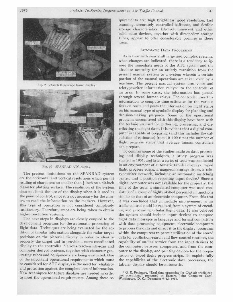
Fig. 9-22-inch Kenoscope Island display.
Fig. 10-SPANRAD ATC display.
The present limitations on the SPANRAD systemare the horizontal and vertical resolutions which permitreading of characters no smaller than '-inch on a 40-inchdiameter plotting surface. The resolution of the systemdoes not limit the use of the display when it is used as
the point of control, since it is not necessary for the cam-era to read the information on the markers. However,this type of operation is not considered completelysatisfactory. Therefore, steps are being taken to obtainhigher resolution systems.The next steps in displays are closely coupled to the
development programs for the automatic processing offlight data. Techniques are being evaluated for the ad-dition of tabular information alongside the radar targetpositions on the pictorial display in order to identifyproperly the target and to provide a more coordinateddisplay to the controller. Various track-while-scan andcomputer-derived systems, together with character gen-
erating tubes and equipments are being evaluated. Oneof the important operational requirements which mustbe considered for ATC displays is the need for reliabilityand protection against the complete loss of information.New techniques for future displays are needed in orderto meet the operational requirements. Among these re-
quirements are: high brightness, good resolution, fastscanning, accurately controlled halftones, and flexiblestorage characteristics. Electroluminescent and othersolid state devices, together with direct-view storagetubes, appear to offer considerable promise in theseareas.
AUTOMATIC DATA PROC-ESSINGAs is true with nearly all large and complex systems,
when changes are indicated, there is a tendency to ig-nore the immediate needs of the ATC system and theabsolute necessity for an orderly transition from thepresent manual system to a system wherein a certainportion of the manual operations are taken over by amachine. The present manual system uses voice andteletypewriter information relayed to the controller ofan area. In some cases, the information has passedthrough several human relays. The controller uses thisinformation to compute time estimates for the variousfixes en route and posts the information on flight stripson his manual type of symbolic display for planning anddecision-making purposes. Some of the operationalproblems encountered with this display have been withthe techniques used for gathering, processing, and dis-tributing the flight data. It is evident that a digital com-puter is capable of preparing (and this includes the cal-culation of estimates) from 10-100 times the number offlight progress strips that average human controllerscan prepare.To confirm some of the studies made on data process-
ing and display techniques, a study program wasstarted in 1951, and later a series of tests was conductedin an environment of automatic tabular displays, typedflight progress strips, a magnetic storage drum, a tele-typewriter network, including an automatic switchingcenter, and a position reporting input device.6 Since adigital computer was not available for the project at thetime of the tests, a simulated computer was used con-sisting of a group of highly skilled personnel in functionssimilar to that of an electronic computer. From this testit was concluded that immediate improvement in airtraffic control could be realized from a system of encod-ing and processing tabular flight data. It was believedthe system should include input devices to composeflight data messages in language and format compatiblewith data processing equipment, electronic computersto process the data and direct it to the display, programswithin the computers to permit utilization of the storeddata for confliction-search and flow-control routines, thecapability of on-line service from the input devices tothe computer, between computers, and from the com-puter to the display, and printing devices for the prepa-ration of typed flight progress strips. To exploit fullythe capabilities of the electronic data processors, thetabular display should be automatic.
6 G. E. Fenimore, 'Real-time processing for CAA air traffic con-trol operations," presented at Eastern Joint Computer Conf.,Washington, D. C.; December 9-13, 1957.
1959 845
PROCEEDINGS OF THE IRE
As a first operational step in December, 1955, a Model650 Digital Computer built by I.B.M. was proposed forthe processing of flight plans and the preparation of fix-posting strips in the Indianapolis Air Route Traffic Con-trol Center. Considerable time was required to preparea detailed program for the computer, since this was thefirst time that machines of this type had been used forthis or similar purposes. The program had to providefor an area containing over 11,000 miles of airways andfor the airway and point-to-point direct route flights.(On an average day about 7000 flight progress stripsmust be prepared, or about 700 strips during a peakhour.) It became apparent during the initial use of thisequipment that additional storage capacity was re-quired. As a result, a Type 355 RAMAC Disk Storagedevice was added to the system and a new program wasdeveloped which included a simple conflict detectionroutine.The use of the computer in the Center is illustrated
in Fig. 11. Incoming flight plans are copied ontopunched cards. The punched cards are read into thecomputers through an input card reader on the 407 ac-counting machine printer. The computer then sorts andrearranges the flight plan data for processing. Since thecomputer program processes either airway or directroute flights, it determines which fixes in the area theflight will pass and computes the estimated time overeach of these fixes. In the case of direct flights, it pro-vides the distance and direction from the nearest fixesthat the aircraft will pass. A simple conflict detectionroutine compares a new flight plan with other flightplans which already have been processed, to determineif aircraft will be over the same fix at the same altitudewithin plus or minus ten minutes. Flight progress stripsare printed out on perforated paper by the 407 printer,separated into individual strips, and inserted into stripholders. Although this separation and insertion now is amanual function, an experimental strip stuffer has beendeveloped and tested which will eliminate this step. Thestrip holders then are distributed to the various postingboards in the control room via belt conveyors.As a result of this initial program, additional com-
puters now are being leased and installed in a number ofother Centers in this country. At the present time, theRemington-Rand UNIVAC File Computers are beingplaced into operation in the New York and WashingtonAir Route Traffic Control Centers.The existing computer equipments being used are
standard off-the-shelf items. In order to permit greaterutilization of automatic data processing, improvements
Fig. 1I-Automatic flight data processing.
are required in the handling of input and output data.Developments are under way at TDC to permit directinput to the system so that the majority of flight planswill be received and read into the computer automat-ically without manual handling. A controller's inputkeyboard will permit the controller to insert flight planchanges directly from the control board. Updated flightdata from the computer will be read out automaticallyat the control boards. Computers in adjacent centerswill be interconnected in order that flight plan data willbe forwarded automatically from center to center. Moresophisticated conflict-detection program routines willbe developed and flow control may be programmed intothe computer. This work is being conducted using boththe IBM-650/RAMAC and Remington-Rand UNIVACequipments at TDC.A more complete approach in applying computers to
air traffic control is being undertaken by the AirwaysModernization Board's (now the Federal AviationAgency's) Phase II program.7 In this approach, a com-plete system including input devices, computers, anddisplays, is being built especially to meet all of theknown operational requirements. Both the in-serviceand this longer range program are closely coordinatedto ensure a smooth transition.
7H. S. Stokes, "Applying computers to air traffic control," IRETRANs. ON AERONAUTICAL AND NAVIGATIONAL ELECTRONICS, VOI.ANE-5, pp. 152-159; September, 1958.