Visit our website at www.raihome.com On-line ordering available. Product Data Sheet PDS 106-340.A01 January, 2005 Oxymitter™ • Outstanding accuracy • Electronics mounted to probe or separate • Adaptable to any existing O 2 probe installation • Advanced sensor diagnostics – alarm indicates when calibration is recommended • Optional explosion-proof rating – ATEX II 2 G EExd IIB + H2 T2/T6 – Class I, Div. I, Groups B, C and D • Digital HART ® communications FOUNDATION™ fieldbus – AMS/PlantWeb ® compatible • Fully field-repairable In Situ Oxygen Transmitter Integral electronics THE LATEST BREAKTHROUGH FOR COMBUSTION FLUE GAS ANALYSIS The Oxymitter In Situ Oxygen Transmitter was the world's first in situ, zirconium oxide-based oxygen transmitter for flue gas measurement. These oxygen measurements can be used in a control system or by a boiler operator to fine tune burner fuel/air ratios for maximum efficiency. Ideal for: • boilers • kilns • process heaters • reheat furnaces Emerson Process Management is the leader in oxygen flue gas analyzer technology. Our in situ, zirconium oxide oxygen analyzers have long been established as industry standards. We've combined our expertise with the latest Rosemount transmitter technology to create a truly revolutionary package – the Oxymitter. The Oxymitter integrates an oxygen probe and field electronics into a single, compact package. The probe inserts directly into a flue gas duct to measure oxygen in combustion processes. No sampling system is required. A NEMA 4X, IP 66 Rosemount transmitter housing mounts directly to the probe and contains the transmitter's electronics, replacing common stand-alone field elec- tronics. This integrated design minimizes the costs of installing separate probe cable, conduit and electronics. The Oxymitter electronics also require 95% less power to operate. So, its components last longer. The HART ® protocol provides a link into Emerson Process Management’s PlantWeb ® field-based architec- ture. Instrument technicians can interface with the Oxymitter from the control room or any location where the transmitter's signal wires terminate. Service diagnostics and calibrations can be performed remotely with a HART hand-held communicator or a personal computer equipped with AMS. The Oxymitter is fully field-repairable. The probe's design provides convenient access to internal probe components so technicians can service the unit in house. The cell and heater/thermocouple are fully field- replaceable. The Oxymitter contains no potentiometer adjustments or jumpers. The Oxymitter In Situ Oxygen Transmitter operates at process temperatures up to 1300°F (700°C), providing a fast response with high accuracy and reliability. Available lengths from 18 inches to 18 feet. Optional accessories for the Oxymitter include: – auto calibration gas sequencer – remote, loop-powered Vacuum Fluorescent display of oxygen reading – high temperature accessories for temperatures up to 1832°F (1000°C) – flame arrestor – abrasive shield Now Offered With Remote Electronics! Remote electronics
Transcript
Visit our website at www.raihome.comOn-line ordering available.
Product Data SheetPDS 106-340.A01January, 2005 Oxymitter™
• Outstanding accuracy
• Electronics mounted to probe orseparate
• Adaptable to any existing O2 probeinstallation
• Advanced sensor diagnostics
– alarm indicates when calibration isrecommended
• Optional explosion-proof rating
– ATEX II 2 G EExd IIB + H2 T2/T6
– Class I, Div. I, Groups B, C and D
• Digital HART® communicationsFOUNDATION™ fieldbus
– AMS/PlantWeb® compatible
• Fully field-repairable
In Situ Oxygen Transmitter
Integral electronics
THE LATEST BREAKTHROUGH FORCOMBUSTION FLUE GAS ANALYSISThe Oxymitter In Situ Oxygen Transmitter was the world'sfirst in situ, zirconium oxide-based oxygen transmitter forflue gas measurement. These oxygen measurementscan be used in a control system or by a boiler operator tofine tune burner fuel/air ratios for maximum efficiency.Ideal for:
• boilers • kilns• process heaters • reheat furnaces
Emerson Process Management is the leader in oxygenflue gas analyzer technology. Our in situ, zirconium oxideoxygen analyzers have long been established as industrystandards. We've combined our expertise with the latestRosemount transmitter technology to create a trulyrevolutionary package – the Oxymitter.
The Oxymitter integrates an oxygen probe and fieldelectronics into a single, compact package. The probeinserts directly into a flue gas duct to measure oxygen incombustion processes. No sampling system is required.
A NEMA 4X, IP 66 Rosemount transmitter housingmounts directly to the probe and contains the transmitter'selectronics, replacing common stand-alone field elec-tronics. This integrated design minimizes the costs of
installing separate probe cable, conduit and electronics.The Oxymitter electronics also require 95% less powerto operate. So, its components last longer.
The HART® protocol provides a link into EmersonProcess Management’s PlantWeb® field-based architec-ture. Instrument technicians can interface with theOxymitter from the control room or any location where thetransmitter's signal wires terminate. Service diagnosticsand calibrations can be performed remotely with a HARThand-held communicator or a personal computerequipped with AMS.
The Oxymitter is fully field-repairable. The probe'sdesign provides convenient access to internal probecomponents so technicians can service the unit inhouse. The cell and heater/thermocouple are fully field-replaceable. The Oxymitter contains no potentiometeradjustments or jumpers.
The Oxymitter In Situ Oxygen Transmitter operates atprocess temperatures up to 1300°F (700°C),providing a fast response with high accuracy andreliability. Available lengths from 18 inches to 18 feet.
Optional accessories for the Oxymitter include:– auto calibration gas sequencer– remote, loop-powered Vacuum Fluorescent display
of oxygen reading– high temperature accessories for temperatures up to 1832°F (1000°C)– flame arrestor– abrasive shield
NowOffered With
Remote Electronics!
Remote electronics
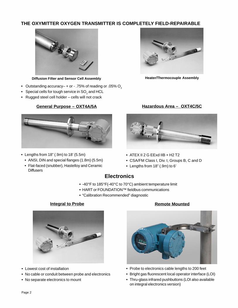
THE OXYMITTER OXYGEN TRANSMITTER IS COMPLETELY FIELD-REPAIRABLE
Diffusion Filter and Sensor Cell Assembly Heater/Thermocouple Assembly
• Outstanding accuracy– + or - .75% of reading or .05% O2
• Special cells for tough service in SO2 and HCL
• Rugged steel cell holder – cells will not crack
Hazardous Area – OXT4C/5CGeneral Purpose – OXT4A/5A
• Lengths from 18” (.9m) to 18’ (5.5m)• ANSI, DIN and special flanges (1.8m) (5.5m)• Flat-faced (snubber), Hastelloy and Ceramic
Diffusers
• ATEX II 2 G EExd IIB + H2 T2• CSA/FM Class I, Div. I, Groups B, C and D• Lengths from 18” (.9m) to 6’
Electronics• -40°F to 185°F(-40°C to 70°C) ambient temperature limit• HART or FOUNDATION™ fieldbus communications• “Calibration Recommended” diagnostic
Integral to Probe Remote Mounted
Page 2
• Probe to electronics cable lengths to 200 feet• Bright gas fluorescent local operator interface (LOI)• Thru-glass infrared pushbuttons (LOI also available
on integral electronics version)
• Lowest cost of installation• No cable or conduit between probe and electronics• No separate electronics to mount
Page 3
OXYMITTER OXYGEN TRANSMITTER FEATURES AND BENEFITS
HART Model 375Hand-held Interface
DIGITAL COMMUNICATIONSCommunicate with the Oxymitter via the FOUNDATION™ Fieldbus Protocol
Features Benefits
Rapid, accurate and reliable measurement of excess Provides inputs for significant fuel savings which normallyoxygen with a single in situ transmitter. pay for the analyzer in less than one year; best accuracy
specification in the industry!
Integrated oxygen probe and electronics simplifies Eliminates costs of mounting separate electronics.installation. Eliminates cabling and conduit between probe and
electronics.
In situ design. No sample system, sample probes, Low installation and maintenance costs.scrubbers, or pumps are necessary; test gas calibrationcheck without disturbing the probe.
Fast speed of response. In situ design ideal for closed loop control.
"Calibration recommended" indication. On-line electrical Optimizes plant resources; reduces maintenance andCAL check indicates need for calibration. calibration costs.
Field-replaceable cell, heater/thermocouple assembly Ease of maintenance.and plug-in electronics module.
Suitable for use in process temperatures up to 1300°F Suitable for use in most combustion applications.(700°C). Optionally up to 1832°F (1000°C).
Material of construction 316 LSS (all wetted parts). High resistance to corrosion.
Cell sensitivity increases logarithmically when oxygen Very useful for low oxygen levels.decreases. Ideal for low excess air burners.
Automatic line voltage selections. Automatically selects from 100 to 240 VAC and 50/60 Hz.without configuration or set-up.
Communicate with the Oxymitter from almost anywhere via the HART™ Protocol
Page 4
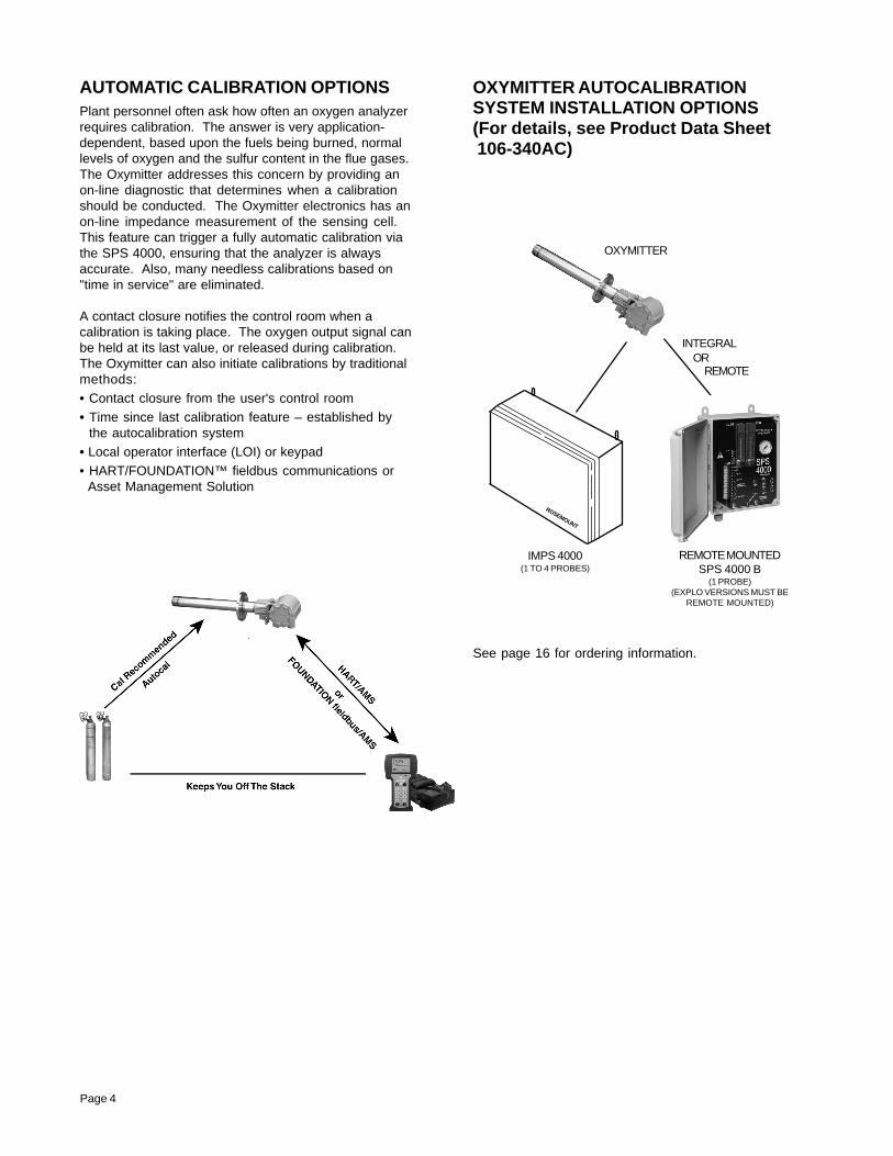
AUTOMATIC CALIBRATION OPTIONSPlant personnel often ask how often an oxygen analyzerrequires calibration. The answer is very application-dependent, based upon the fuels being burned, normallevels of oxygen and the sulfur content in the flue gases.The Oxymitter addresses this concern by providing anon-line diagnostic that determines when a calibrationshould be conducted. The Oxymitter electronics has anon-line impedance measurement of the sensing cell.This feature can trigger a fully automatic calibration viathe SPS 4000, ensuring that the analyzer is alwaysaccurate. Also, many needless calibrations based on"time in service" are eliminated.
A contact closure notifies the control room when acalibration is taking place. The oxygen output signal canbe held at its last value, or released during calibration.The Oxymitter can also initiate calibrations by traditionalmethods:• Contact closure from the user's control room• Time since last calibration feature – established by the autocalibration system• Local operator interface (LOI) or keypad• HART/FOUNDATION™ fieldbus communications or Asset Management Solution
OXYMITTER AUTOCALIBRATIONSYSTEM INSTALLATION OPTIONS(For details, see Product Data Sheet 106-340AC)
Accuracy: Typically ±0.75% of reading or 0.05%O2, whichever is greaterLowest detectable limit – .05% O2
System Response to Test Gas:Initial response in less than 3 secondsT90 in less than 8 seconds
843 C SPECIFICATIONTemperature Limits: Process: 32° to 1300°F (0° to 704°C) up to 1832°F
(1000°C) with optional accessories
Electronics/Probe:-40° to 185°F (-40° to 85°C) actual temperatureinside electronics
Local operator interface: -40° to 185°F (-40° to 85°C)
IR thru-glass push buttons: -40° to 158°F (-40° to 70°C)
Probe Lengths, Nominal and Approximate ShippingWeights:
18 in. (457 mm) package: 16 pounds (7.3 kg)3 foot (0.91 m) package: 21 pounds (9.5 kg)6 foot (1.83 m) package: 27 pounds (12.2 kg)9 foot (2.74 m) package: 33 pounds (15.0 kg)12 foot (3.66 m) package: 39 pounds (17.7 kg)15 foot (4.6 m) package: 45 pounds (20.5 kg)18 foot (5.5 m) package: 51 pounds (23 kg)
Mounting and Mounting Position:Vertical or horizontalSpool pieces are available, P/N 3D39761G02,to offset transmitter housing from hot ductwork.
Materials:
Probe: Wetted or welded parts – 316L stainless steel
Non-wetted parts – 304 stainless steel,low-copper aluminum
Electronics Enclosure:Low-copper aluminum
Calibration: Semi-automatic or automatic
Calibration Gas Mixtures Recommended:0.4% O2, balance N2, 8% O2, balance N2(Ref. test gas kit #6296A27G01)
Calibration Gas Flow:5 scfh (2.5 l/m)
Reference Air 2 scfh (1 l/m), clean, dry, instrument-quality (optional): air (20.95% O2), regulated to 5 psi (34 kPa)
Electronics: NEMA 4X, IP 66 with fitting and pipe onreference exhaust port to clean dryatmosphere
The Oxymitter field electronics mount directly to the oxygenprobe in a standard NEMA 4X, IP 66 housing.
1 All static performance characteristics are with operating variablesconstant. Specifications subject to change without notice.
Emerson Process Management has satisfied all obligationscoming from the European legislation to harmonize theproduct requirements in Europe.
Electrical Noise:Meets EN 55082 Generic Emissions Standard
EN 61000-4-2 Electrostatic Discharge
EN 61000-4-3 Radio Frequency Interference
EN 61000-4-6 Radio Frequency Interference
EN 61000-4-4 Fast Transient Immunity
Optional Hazardous AreaCertifications:
Hazardous Area Oxymitter with Integral Electronics:
KEMA/ATEX II 2 G EEx d IIB+H2 T6 (Elect Comp)/T2 (Probe)
CSA Class I, Division 1, Groups B, C, D T2Class I, Zone 1, Ex d IIB+H2 T2Class I, Zone 1, AEx d IIB+H2 T2
FM Class I, Division 1, Groups B, C, D T2Class I, Zone 1, AEx d IIB+H2 T2
Hazardous Area Oxymitter with Remote Electronics:
KEMA/ATEX II 2 G EEx d IIB+H2 T2 (Remote Probe)II 2 G EEx de IIB+H2 T6 (Remote Electronics)
CSA Class I, Zone 1, Ex d IIB+H2 T2 (Remote Probe)Class I, Zone 1, Ex de IIB+H2 T6 (RemoteElectronics)Class I, Zone 1, AEx d IIB+H2 T2 (Remote Probe)Class I, Zone 1, AEx de IIB+H2 T6 (RemoteElectronics)
FM Class I, Zone 1, AEx d IIB+H2 T2 (Remote Probe)Class I, Zone 1, AEx de IIB+H2 T6 (RemoteElectronics)
Line Voltage: Universal 100 to 240 ± 10% VAC, 50-60 HZno switches or jumpers required 3/4"– 14 NPT conduit port
Isolated Output/Hart or FOUNDATION™ fieldbus:One 4-20mAdc, 950 ohm maximum loadisolated with Hart capability for 4000 ordigital FOUNDATION fieldbus signal for 5000.
2 Terminal Logic Contact:Configurable as either an alarm output(Relay or Logic) or as a bi-directionalcalibration handshake signal to calibrationgas sequencer. Self-powered, (+5V)340 ohm series resistance
3/4"–14 NPT (one threaded hole for bothanalog output and logic I/O)
Power Consumption Limits:
Power Consumption of Probe Heater:175 W nominal maximum
Power Consumption of Electronics:10 W nominal maximum
Fieldbus Segment Power Consumption:17.5 or 19mA
Page 6
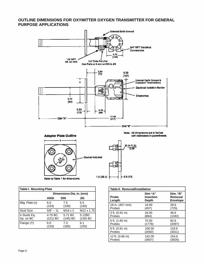
OUTLINE DIMENSIONS FOR OXYMITTER OXYGEN TRANSMITTER FOR GENERALPURPOSE APPLICATIONS
Table I. Mounting Plate
Dimensions Dia. in. (mm)
ANSI DIN JIS
Mtg. Plate (x) 6.0 7.5 6.5(153) (190) (165)
Stud Size 5/8" – 11 M16 x 2 M12 x 1.75
4 Studs Eq. 4.75 BC 5.71 BC 5.12BCSp. on BC (121) BC (145) BC (130) BC
Flange (Y) 6.0 7.3 6.1(153) (185) (155)
Table II. Removal/Installation
Dim “A” Dim. “B”Probe Insertion RemovalLength Depth Envelope
18 in. (457 mm) 16.00 28.6Probes (407) (725)
3 ft. (0.91 m) 34.00 46.6Probes (864) (1182)
6 ft. (1.83 m) 70.00 82.6Probes (1778) (2097)
9 ft. (0.91 m) 106.00 118.6Probes (2692) (3011)
12 ft. (3.66 m) 142.00 154.6Probes (3607) (3926)
Page 7
ORDERING INFORMATION – General Purpose Oxymitter with 4-20 mA Output Signal,and HART® Communications
Model DescriptionOXT4A In Situ Oxygen Transmitter – HART Smart (Oxymitter)
Level 1 Sensing Probe Type1 Ceramic diffusion element probe (ANSI)2 Flame arrestor probe (ANSI) (ceramic diffusion element)3 Snubber diffusion element (ANSI)4 Ceramic diffusion element probe (DIN)5 Flame arrestor probe (DIN) (snubber diffusion element)6 Snubber diffusion element (DIN)7 Ceramic diffusion element probe (JIS)8 Flame arrestor probe (JIS) (ceramic diffusion element)9 Snubber diffusion element (JIS)
Level 2 Probe Assembly0 18 in. (457 mm) probe1 18 in. (457 mm) probe with abrasive shield 1
2 3 ft. (0.91 m) probe3 3 ft. (0.91 m) probe with abrasive shield 1
4 6 ft. (1.83 m) probe5 6 ft. (1.83 m) probe with abrasive shield 1
6 9 ft. (2.74 m) probe7 9 ft. (2.74 m) probe with abrasive shield 1
8 12 ft. (3.66 m) probe9 12 ft. (3.66 m) probe with abrasive shield 1
A 15 ft. (4.57 m) probe with abrasive shield 1
B 18 ft. (5.49 m) probe with abrasive shield 1
Level 3 Mounting Hardware (stack side)0 No mounting hardware (must be chosen under mounting adapter – probe side)1 New Installation – square weld plate with studs2 Mounting to Model 218 mounting plate (with Model 218 shield removed)3 Mounting to existing Model 218 support shield4 Mounting to other mounting 2
5 Mounting to Model 132 adapter plate
Level 4 Mounting Hardware (probe side)0 No mounting hardware1 Probe only (ANSI)2 New bypass or new abrasive shield (ANSI)4 Probe only (DIN)5 New bypass or new abrasive shield (DIN)7 Probe only (JIS)8 New bypass or new abrasive shield (JIS)
Level 5 Electronic Housing and Filtered Customer Termination – NEMA 4X, IP 6611 Electronics integrally mounted to probe with standard filtered termination12 For HART® electronics integrally mounted to probe with transient protected filtered termination13 Electronics mounted remotely with standard filtered termination; requires cable14 For HART® electronics mounted remotely with transient protected filtered termination – requires cable
Level 6 Communications1 Membrane keypad – HART capable, blind cover2 Membrane keypad – HART capable, glass cover3 Gas florescent LOI HART capable, glass cover, English only
Page 8
Level 7 Language LOI Accepts English Language Only1 English2 German3 French4 Spanish5 Italian
Level 8 Termination Filtering00 Specified as part of electronic housing
Level 9 Calibration Accessories00 No hardware01 Cal./ref. flowmeter and ref. pressure regulator02 Autocalibration Systems – order by separate part number, for safe areas only or purged by user
Level 10 Electronics to Probe Cable00 No cable10 20 ft. (6 m) cable11 40 ft. (12 m) cable12 60 ft. (18 m) cable13 80 ft. (24 m) cable14 100 ft. (30 m) cable15 150 ft. (45 m) cable16 200 ft. (61 m) cable
ORDERING INFORMATION (continued)
Note:1 Recommended usages: high velocity particulates in flue stream, installation within 10 ft. (3.5 m) of soot blowers or heavy salt cake build-up.
Applications: pulverized coal, recovery boilers, lime kiln. Regardless of application, abrasive shields with support brackets are recommendedfor 9 ft. and 12 ft. probe installations, particularly horizontal installations.
2 Where possible, specify SPS number; otherwise provide details of existing mounting plate as follows:
Plate with studs Bolt circle diameter, number and arrangement of studs, stud thread, stud height above mounting plate.
Plate without studs Bolt circle diameter, number and arrangement of holes, thread, depth of stud mounting plate with accessories.
Page 9
ORDERING INFORMATION – General Purpose Oxymitter with FOUNDATION™ FieldbusCommunications
Model DescriptionOXT5A In Situ Oxygen Transmitter – with FOUNDATION™ fieldbus (Oxymitter 5000)
Level 1 Sensing Probe Type1 Ceramic diffusion element (ANSI)2 Ceramic diffusion element flame arrestor (ANSI) general purpose only3 Snubber diffusion element (ANSI)4 Ceramic diffusion element (DIN)5 Snubber diffusion element flame arrestor (DIN) general purpose only6 Snubber diffusion element (DIN)7 Ceramic diffusion element (JIS)8 Ceramic diffusion element flame arrestor (JIS) general purpose only9 Snubber diffusion element (JIS)
Level 2 Probe Assembly0 18 in. (457 mm) probe1 18 in. (457 mm) probe with abrasive shield 1
2 3 ft. (0.91 m) probe3 3 ft. (0.91 m) probe with abrasive shield 1
4 6 ft. (1.83 m) probe5 6 ft. (1.83 m) probe with abrasive shield 1
6 9 ft. (2.74 m) probe7 9 ft. (2.74 m) probe with abrasive shield 1
8 12 ft. (3.66 m) probe9 12 ft. (3.66 m) probe with abrasive shield 1
A 15 ft. (4.57 m) probe with abrasive shield 1
B 18 ft. (5.49 m) probe with abrasive shield 1
Level 3 Mounting Hardware (stack side)0 No adapter plate1 New Installation – square weld plate with studs2 Mounting to Model 218 (with Model 218 shield removed)3 Mounting to existing Model 218 support shield4 Competitor’s mount 2
5 Mounting to Model 132 adapter plate
Level 4 Mounting Hardware (probe side)0 No mounting hardware in adapter plate1 Probe only (ANSI)2 New bypass or new abrasive shield (ANSI)4 Probe only (DIN)5 New bypass or new abrasive shield (DIN)7 Probe only (JIS)8 New probe or abrasive shield (JIS)
Level 5 Electronic Housing – NEMA 4X, IP 6612 Transient protected filtered termination, integrally mounted to probe14 Transient protected filtered termination, mounted remotely – requires cable
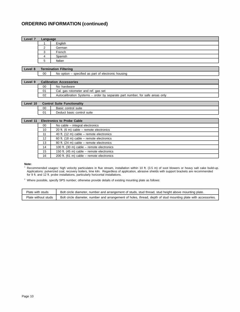
Level 7 Language1 English2 German3 French4 Spanish5 Italian
Level 8 Termination Filtering00 No option – specified as part of electronic housing
Level 9 Calibration Accessories00 No hardware01 Cal. gas rotometer and ref. gas set02 Autocalibration Systems – order by separate part number, for safe areas only
Level 10 Control Suite Functionality00 Basic control suite01 Deduct basic control suite
Level 11 Electronics to Probe Cable00 No cable – integral electronics10 20 ft. (6 m) cable – remote electronics11 40 ft. (12 m) cable – remote electronics12 60 ft. (18 m) cable – remote electronics13 80 ft. (24 m) cable – remote electronics14 100 ft. (30 m) cable – remote electronics15 150 ft. (45 m) cable – remote electronics16 200 ft. (61 m) cable – remote electronics
ORDERING INFORMATION (continued)
Note:1 Recommended usages: high velocity particulates in flue stream, installation within 10 ft. (3.5 m) of soot blowers or heavy salt cake build-up.
Applications: pulverized coal, recovery boilers, lime kiln. Regardless of application, abrasive shields with support brackets are recommendedfor 9 ft. and 12 ft. probe installations, particularly horizontal installations.
2 Where possible, specify SPS number; otherwise provide details of existing mounting plate as follows:
Plate with studs Bolt circle diameter, number and arrangement of studs, stud thread, stud height above mounting plate.
Plate without studs Bolt circle diameter, number and arrangement of holes, thread, depth of stud mounting plate with accessories.
Page 11
OUTLINE DIMENSIONS FOR OXYMITTER HAZARDOUS AREA OXYGEN TRANSMITTER
Table I. Mounting PlateDimensions Dia. in. (mm)ANSI DIN
Mtg. Plate (x) 7.75 8.5(197) (215)
Stud Size 5/8" – 11 M16 x 24 Studs Eq. 6.00 BC 6.70 BCSp. on BC (152.4) BC (170) BCFlange (Y) 7.5 8.27
(190) (210)
Table II. Removal/InstallationDim “A” Dim. “B”
Probe Insertion RemovalLength Depth Envelope18 in. (457 mm) 18.1 31.6Probes (460) (803)3 ft. (0.91 m) 36.1 57.0Probes (917) (1448)6 ft. (1.83 m) 72.1 85.6Probes (1831) (2174)
ORDERING INFORMATION – Hazardous Area Oxymitter with HART® Communications
Model DescriptionOXT4C In Situ Oxygen Transmitter – Explo-Proof – HART Smart (Oxymitter 4000)
Level 1 Sensing Probe Type With Flame Arrestor1 Ceramic diffusion element probe (ANSI 3” 150 lb. bolt circle)2 Snubber diffusion element (ANSI 3” 150 lb. bolt circle)3 Ceramic diffusion element probe (DIN 2527) 1/4” tube fittings4 Snubber diffusion element (DIN 2527) 1/4” tube fittings7 Ceramic diffusion element probe (ANSI 3” 300 lb. bolt circle) 1
Level 2 Probe Assembly0 18 in. probe1 18 in. probe with 3 ft. bypass2 18 in. probe with abrasive shield
2
3 3 ft. probe4 3 ft. probe with abrasive shield 2
5 6 ft. probe6 6 ft. probe with abrasive shield 2
Level 3 Mounting Adapter (stack side)0 No adapter plate (0 must also be chosen under mounting adapter – probe side)1 New Installation – square weld plate with studs2 Model 218 mounting plate (with Model 218 shield removed)3 Competitor’s mount
2
Level 4 Mounting Adapter (probe side)0 No adapter plate1 Probe only (ANSI)2 New bypass or new abrasive shield (ANSI)4 Probe only (DIN)5 New bypass or new abrasive shield (DIN)
Level 5 Electronic Housing and Filtered Customer Termination – NEMA 4X, IP 6612 HART® electronics, mounted integral to probe, transient protected termination, ATEX EExd IIB + H2 T2 certification14 HART® electronics, mounted remotely with transient protected termination, requires cable ATEX EExd
IIB + H2 T2 certification
22 HART® electronics, mounted integral to probe, transient protected termination, CSA/FM Class I, Zone I, Groups B, Cand D
24 HART® electronics, mounted remotely, transient protected termination; requires cable CSA/FM Class I, Div. I, GroupsB, C and D
Level 6 Communications1 Membrane keypad – HART capable 2 Membrane keypad – HART capable, glass window 3 Gas florescent LOI HART capable, glass window, English only
Page 12
Page 13
ORDERING INFORMATION (continued)
NOTES:1 Probe is set up for high acid service in catalytic regenerators; includes: SO2/ HCL resistant cell, Hastelloy C and Viton materials for
calibration gas line larger than standard flange. Acid service cells are available for other probes ordered separately. 2 Recommended usages: high velocity particilates in flue stream, installation within 10 ft. (3.5 m) of soot blowers or heavy salt cake build-up.
Applications: pulverized coal, recovery boilers, lime kiln. Regardless of application, abrasive shields with support brackets are recommended for9 ft. (2.74 m) and 12 ft. (3.65 m) probe installations, particularly horizontal installations.
3 Where possible, specify SPS number; otherwise provide details of the existing mounting plate as follows:
Level 7 Language LOI Accepts English Language Only1 English2 German3 French4 Spanish5 Italian
Level 8 Termination Filtering00 Specified as part of electronic housing
Level 9 Calibration Accessories00 No hardware01 Cal./ref. flowmeter and ref. pressure regulator02 Autocalibration Systems – order by separate part number, for safe areas only or purged by user
Level 10 Electronics to Probe Cable00 No cable10 20 ft. (6 m) cable11 40 ft. (12 m) cable12 60 ft. (18 m) cable13 80 ft. (24 m) cable14 100 ft. (30 m) cable15 150 ft. (45 m) cable16 200 ft. (61 m) cable
Plate with studs Bolt circle diameter, number and arrangement of studs, stud thread, stud height above mounting plate.
Plate without studs Bolt circle diameter, number and arrangement of holes, thread, depth of stud mounting plate with accessories.
ORDERING INFORMATION – Hazardous Area with FOUNDATION™ FieldbusCommunications
Model DescriptionOXT5C In Situ Oxygen Transmitter – Explo-Proof with FOUNDATION™ fieldbus (Oxymitter 5000)
Level 1 Sensing Probe Type With Flame Arrestor1 Ceramic diffusion element probe (ANSI 3” 150 lb. bolt circle)2 Snubber diffusion element (ANSI 3” 150 lb. bolt circle)3 Ceramic diffusion element probe (DIN 2527) 1/4” tube fittings4 Snubber diffusion element (DIN 2527) 1/4” tube fittings7 Ceramic diffusion element probe (ANSI 3” 300 lb. bolt circle) 1
Level 2 Probe Assembly0 18 in. probe2 18 in. probe with abrasive shield
2
3 3 ft. probe4 3 ft. probe with abrasive shield 2
5 6 ft. probe6 6 ft. probe with abrasive shield 2
Level 3 Mounting Adapter (stack side)0 No adapter plate1 New Installation – square weld plate with studs2 Model 218 mounting plate (with Model 218 shield removed)3 Competitor’s mount
2
Level 4 Mounting Adapter (probe side)0 No adapter plate1 Probe only (ANSI)2 New bypass or new abrasive shield (ANSI)4 Probe only (DIN)5 New bypass or new abrasive shield (DIN)7 Probe only (JIS)8 New bypass or new abrasive shield (JIS)
Level 5 Electronic Housing – NEMA 4X, IP 6612 FOUNDATION™ fieldbus electronics, mounted integral to probe, transient protected termination, ATEX EExd IIB +
Level 7 Language1 English2 German3 French4 Spanish5 Italian
Level 8 Termination Filtering00 No option – specified as part of electronic housing
Level 9 Calibration Accessories00 No hardware01 Cal./ref. flowmeter and ref. pressure regulator02 Autocalibration Systems – order by separate part number, for safe areas only, or purged by user
Level 10 Hazardous Area Approval 10 ATEX 20 CSA – Class I, Division I, Groups B, C and D, T2/T6 (electronics)
Level 11 Control Suite Functionality 00 Basic Control Suite 01 Deduct Basic Control Suite
Level 12 Electronics to Probe Cable00 No cable – integral electronics10 20 ft. (6 m) cable – remote electronics11 40 ft. (12 m) cable – remote electronics12 60 ft. (18 m) cable – remote electronics13 80 ft. (24 m) cable – remote electronics14 100 ft. (30 m) cable – remote electronics15 150 ft. (45 m) cable – remote electronics16 200 ft. (61 m) cable – remote electronics
NOTES:1 Probe is set up for high acid service in catalytic regenerators; includes: SO2/ HCL resistant cell, Hastelloy C and Viton materials for
calibration gas line larger than standard flange. Acid service cells are available for other probes ordered separately. 2 Recommended usages: high velocity particilates in flue stream, installation within 10 ft. (3.5 m) of soot blowers or heavy salt cake build-up.
Applications: pulverized coal, recovery boilers, lime kiln. Regardless of application, abrasive shields with support brackets are recommended for9 ft. (2.74 m) and 12 ft. (3.65 m) probe installations, particularly horizontal installations.
3 Where possible, specify SPS number; otherwise provide details of the existing mounting plate as follows:
Plate with studs Bolt circle diameter, number and arrangement of studs, stud thread, stud height above mounting plate.
Plate without studs Bolt circle diameter, number and arrangement of holes, thread, depth of stud mounting plate with accessories.
LIST PART NUMBERS AS SEPARATE LINE ITEMS:The Intelligent Multiprobe Sequencer (IMPS) will automatically calibrate up to 4 probes.
Rosemount Analytical no longer offers an integral Z-purge option for its oxygen (O2) analyzers. However, the IFT, MPSand IMPS enclosures are still capable of Z or X purge by the customer.
Part Number Description1A99119G01 Two disposable gas bottles – .4% and 8% O2 balance nitrogen 550 liters each
1A99119G02 Two pressure regulators for cal. gas bottles
1A99119G03 Bottle rack
CALIBRATION GAS BOTTLES 1
1 Bottles cannot be shipped via airfreight.
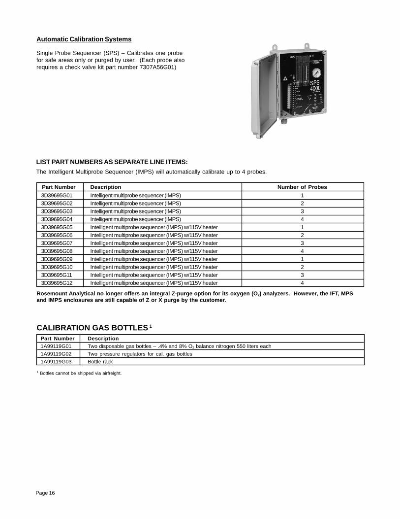
Automatic Calibration Systems
Single Probe Sequencer (SPS) – Calibrates one probefor safe areas only or purged by user. (Each probe alsorequires a check valve kit part number 7307A56G01)
The FOUNDATION™ fieldbus 375 Communicator is aninterface device that provides a common communicationlink to HART®/FOUNDATION fieldbus compatible instru-ments, such as the Sulfur-Resistant Oxymitter. HART®
Communications Protocol permits all the informationavailable from the Sulfur-Resistant Oxymitter electronicsto be transmitted over standard 4-20 mA signal wires orFOUNDATION fieldbus wires. By attaching the hand-heldcommunicator at a termination point along the signalline, a technician can diagnose problems and configureand calibrate the Sulfur-Resistant Oxymitter as if he or she were standing in frontof the instrument.
For more information, call Rosemount Analytical at1-800-433-6076.
Bypass Packages
The specially designed Rosemount Analytical BypassPackage for oxygen analyzers has proven to withstandthe high temperatures in process heaters while provid-ing the same advantages offered by the in situ sensor.Inconel tubes provide effective resistance to corrosion,and the other components common to other samplingsystems.
For more information, call Rosemount Analytical at1-800-433-6076.
O2 Calibration Gas Kits
Rosemount Analytical's O2 Calibration Gas andService Kits have been carefully designed to provide amore convenient and fully portable means of testing,calibrating, and servicing Rosemount Analytical's oxygenanalyzers. These lightweight, disposable gas cylinderseliminate the need to rent gas bottles.
For more information, call Rosemount Analytical at1-800-433-6076.
Page 18
SPECIAL ARRANGEMENTS
Special Cells for High Acid ServiceMany combustion processes use fuels that containsulfur of HCI. Special cells provide extended life in thesedifficult applications.
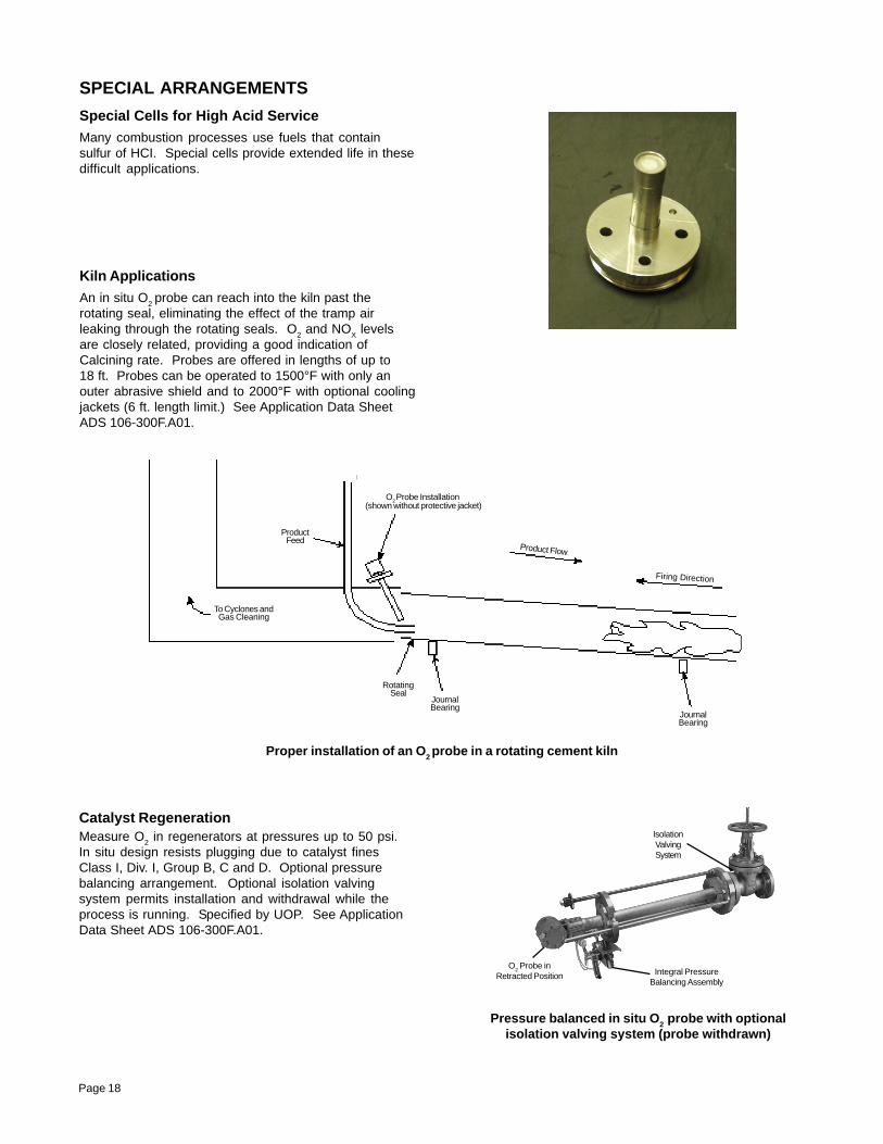
Proper installation of an O2 probe in a rotating cement kiln
Kiln ApplicationsAn in situ O2 probe can reach into the kiln past therotating seal, eliminating the effect of the tramp airleaking through the rotating seals. O2 and NOX levelsare closely related, providing a good indication ofCalcining rate. Probes are offered in lengths of up to18 ft. Probes can be operated to 1500°F with only anouter abrasive shield and to 2000°F with optional coolingjackets (6 ft. length limit.) See Application Data SheetADS 106-300F.A01.
Catalyst RegenerationMeasure O2 in regenerators at pressures up to 50 psi.In situ design resists plugging due to catalyst finesClass I, Div. I, Group B, C and D. Optional pressurebalancing arrangement. Optional isolation valvingsystem permits installation and withdrawal while theprocess is running. Specified by UOP. See ApplicationData Sheet ADS 106-300F.A01.
Pressure balanced in situ O2 probe with optionalisolation valving system (probe withdrawn)
O2 Probe Installation (shown without protective jacket)
Product Flow
Firing Direction
ProductFeed
To Cyclones andGas Cleaning
RotatingSeal
JournalBearing
JournalBearing
IsolationValvingSystem
Integral PressureBalancing Assembly
O2 Probe in
Retracted Position
Page 19
Emerson Process ManagementRosemount Analytical Inc.Process Analytic Division1201 North Main StreetOrrville, OH 44667-0901 USAT 330.682.9010Toll Free in US and Canada 800.433.6076F 330.684.4434e-mail: [email protected]
The contents of this publication are presented for informational purposes only, and while every effort has been made to ensure their accuracy, they are not tobe construed as warranties or guarantees, express or implied, regarding the products or services described herein or their use or applicability. All sales aregoverned by our terms and conditions, which are available on request. We reserve the right to modify or improve the designs or specifications of our productsat any time without notice.