45


2
In the Bid Book (pages 192 and 193) REMOVE “SPECIAL PROVISION, SECTION 621, LANDSCAPE” 2 pages dated October 8, 2013 and REPLACE with the attached new “SPECIAL PROVISION, SECTION 621, LANDSCAPE” 1 page dated November 1, 2013. In the Bid Book, after page 218, ADD the attached “SPECIAL PROVISION, SECTION 635, PRECAST AGGREREGATE-FILLED, CONCRETE BLOCK GRAVITY WALL”, 9 pages. In the Plans, Sheet Number 4B of 91, “ESTIMATED QUANTITIES” Make the following CHANGES in pen and ink; ADD the following items; ITEM DESCRIPTION TOTAL UNIT 621.279 Med. Dec Trees 2 1/2” – 3”cal .B&B Gr.A 6 EA 621.2021 Med. Dec Trees 2 1/2” – 3”cal .B&B Gr.B 6 EA 635.40 PRECAST AGGREGATE FILLED, CONCRETE 120 SF BLOCK GRAVITY WALL DELETE the following Item; ITEM DESCRIPTION TOTAL UNIT 621.28 MEDIUM DECID. TREES 2.5” – 3” GROUP B 18 EA In the Plans, Sheet Number 5 of 91, “GERERAL NOTES’ make the following two CHANGES in pen and ink; 1. Note #5 DELETE in its entirety and REPLACE with the following; “Stump removal shall be paid for under item 631.20, as approved by the Resident.” 2. Note #57 DELETE in its entirety and REPLACE with the following; “Two reflectorized flexible G.R. markers (item 606.353) will be installed at each guardrail end.” In the Plans, Sheet Number 35 of 91, “SIGNAL NOTES”, note # 20, CHANGE the last sentence to read as follows; “This work will be incidental to item 643.71.” Make this change in pen and ink. In the Plans, Sheet Number G-1 of 3, ADD the following note in pen and ink; “2. RETAINING WALLS ASSOCIATED WITH APPENDIX G OF TH E CONTRACT PLANS SHALL CONSIST OF EITHER PRECAST CONC RETE BLOCK GRAVITY WALL (PAY ITEM 635.31) OR PRECAST AGG REGATE-FILLED, CONCRETE BLOCK GRAVITY WALL (PAY ITEM 635.4 0).” In the Plans, Sheet Number G-2 of 3, right hand side of the plan sheet CHANGE the note that reads “EXISTING METAL CRIB WALL APPROX. STA 22+99 TO STA 23+46 (TO BE REMOVED) REMOVAL OF EXISTING CRIB WALL SHALL BE INCIDENTAL TO MDOT PAY ITEM 635.31 CONSTRUCTION OF NEW WALL.” To read as follows “EXISTING METAL CRIB WALL APPROX. STA 22+99 TO STA 23+46 (TO BE REMOVED) REMOVAL OF EXISTING CRIB WALL SHALL BE

3
INCIDENTAL TO MDOT PAY ITEM 635.31 OR MDOT PAY ITEM 635.40 CONSTRUCTION OF NEW WALL .” Make this change in pen and ink. The following questions have been received: Question: The location of the retaining wall (line item 1120 – SP 635.31-Prefab Concrete Block Gravity Wall – 120 SF), is referred to on sheet G-2. However, I saw no plan view or elevation view of the intended wall. Will plan & elevation views of the intended retaining wall be made available?
Response: No, the intent of this wall is to be a vendor-designed, based on field conditions. Additional details will not be provided with the bid documents. The contractor shall bid on this wall based on the information provided in plan, topo, and the estimated quantities included with the contract documents. This addendum includes pictures showing the existing trail conditions which are to be replaced with a new trail and retaining wall. Pictures are included for information purposes only. Question: Is a licensed engineer’s wall design required for the retaining wall, line item 1120? Response: The wall design may require a licensed engineer to meet Special MDOT Provisions, Specification 635 Precast Concrete Block Gravity Wall or 635 Precast Aggregate – Filled Gravity Wall, such as when the exposed wall height exceeds 4.5 feet. Question: Please confirm (pg210 (2 of 10)) that “pigment shall be added during the casting process of the concrete unit to achieve a consistent shade of gray or other color as determined by the resident.” (This is an added production step that is not always required.) Response: Yes, this is a requirement. Question: Has a specific Block Face been established? Is: Limestone or Cobblestone? Response: No, the block Face has not been selected. After contract award, cut-sheets of available wall face treatments shall be provided to the Resident for selection. The selected face treatment shall then be incorporated into the shop-drawings required as part of the submittal-approval process. Question: Reference Special Provision 621. Please review, the quantities do not total. Response: Please see the above Special Provision 621 change.


MAINE DEPARTMENT OF TRANSPORTATION PAGE: 1 DATE: 131104 SCHEDULE OF ITEMS REVISED: CONTRACT ID: 017336.00 PROJECT(S): STP-1733(600) STP-1838(900) 018394.00 OTHERS CONTRACTOR :________________________________________________________________ ------------------------------------------------------------------------------- LINE| ITEM | APPROX. | UNIT PRICE | BID AMOUNT NO | DESCRIPTION | QUANTITY |----------------|-------------- | | AND UNITS | DOLLARS | CTS | DOLLARS |CTS ------------------------------------------------------------------------------- SECTION 0001 THOMPSON PT RD/EXIT 5 ------------------------------------------------------------------------------- |202.129 REMOVE EXISTING | | | | | 0010|WOODEN SIDEWALK BRIDGE |LUMP |LUMP | | | | | | | | | ------------------------------------------------------------------------------- |202.15 REMOVING MANHOLE | | | | | 0020|OR CATCH BASIN | 5.000| | | | | |EA | | | | ------------------------------------------------------------------------------- |202.2004 REMOVE AND | | | | | 0030|RELOCATE BUS SHELTER |LUMP |LUMP | | | | | | | | | ------------------------------------------------------------------------------- |202.203 PAVEMENT BUTT | | | | | 0040|JOINTS | 1267.000| | | | | |SY | | | | ------------------------------------------------------------------------------- |203.20 COMMON EXCAVATION | | | | | 0050| | 6802.000| | | | | |CY | | | | ------------------------------------------------------------------------------- |203.2312 HEALTH AND | | | | | 0060|SAFETY PLAN |LUMP |LUMP | | | | | | | | | ------------------------------------------------------------------------------- |203.24 COMMON BORROW | | | | | 0070| | 1099.000| | | | | |CY | | | | ------------------------------------------------------------------------------- |203.25 GRANULAR BORROW | | | | | 0080| | 239.000| | | | | |CY | | | | ------------------------------------------------------------------------------- |206.061 STRUCTURAL EARTH | | | | | 0090|EXCAVATION - DRAINAGE | 60.000| | | | |AND MINOR STRUCTURES, |CY | | | | |BELOW GRADE | | | | | -------------------------------------------------------------------------------

MAINE DEPARTMENT OF TRANSPORTATION PAGE: 2 DATE: 131104 SCHEDULE OF ITEMS REVISED: CONTRACT ID: 017336.00 PROJECT(S): STP-1733(600) STP-1838(900) 018394.00 OTHERS CONTRACTOR :________________________________________________________________ ------------------------------------------------------------------------------- LINE| ITEM | APPROX. | UNIT PRICE | BID AMOUNT NO | DESCRIPTION | QUANTITY |----------------|-------------- | | AND UNITS | DOLLARS | CTS | DOLLARS |CTS ------------------------------------------------------------------------------- |304.09 AGGREGATE BASE | | | | | 0100|COURSE - CRUSHED | 161.000| | | | | |CY | | | | ------------------------------------------------------------------------------- |304.10 AGGREGATE SUBBASE | | | | | 0110|COURSE - GRAVEL | 4170.000| | | | | |CY | | | | ------------------------------------------------------------------------------- |403.207 HOT MIX ASPHALT | | | | | 0120|19.0 MM HMA | 731.000| | | | | |T | | | | ------------------------------------------------------------------------------- |403.208 HOT MIX ASPHALT | | | | | 0130|12.5 MM HMA SURFACE | 661.000| | | | | |T | | | | ------------------------------------------------------------------------------- |403.209 HOT MIX ASPHALT | | | | | 0140|9.5 MM (SIDEWALKS, | 800.000| | | | |DRIVES, INCIDENTALS) |T | | | | ------------------------------------------------------------------------------- |403.211 HOT MIX ASPHALT | | | | | 0150|(SHIMMING) | 55.000| | | | | |T | | | | ------------------------------------------------------------------------------- |403.213 HOT MIX ASPHALT | | | | | 0160|12.5 MM BASE | 406.000| | | | | |T | | | | ------------------------------------------------------------------------------- |409.15 BITUMINOUS TACK | | | | | 0170|COAT - APPLIED | 288.000| | | | | |G | | | | ------------------------------------------------------------------------------- |411.13 STONE DUST | | | | | 0180|SURFACE COURSE | 170.000| | | | | |T | | | | ------------------------------------------------------------------------------- |502.461 STRUCTURAL | | | | | 0190|CONCRETE, REPLACE | 132.000| | | | |CONCRETE SLAB. |CY | | | | -------------------------------------------------------------------------------

MAINE DEPARTMENT OF TRANSPORTATION PAGE: 3 DATE: 131104 SCHEDULE OF ITEMS REVISED: CONTRACT ID: 017336.00 PROJECT(S): STP-1733(600) STP-1838(900) 018394.00 OTHERS CONTRACTOR :________________________________________________________________ ------------------------------------------------------------------------------- LINE| ITEM | APPROX. | UNIT PRICE | BID AMOUNT NO | DESCRIPTION | QUANTITY |----------------|-------------- | | AND UNITS | DOLLARS | CTS | DOLLARS |CTS ------------------------------------------------------------------------------- |512.07 FRENCH DRAINS | | | | | 0200|(STONES ONLY) | 92.000| | | | | |CY | | | | ------------------------------------------------------------------------------- |527.3032 ENERGY | | | | | 0210|ABSORBING SYSTEM | 2.000| | | | |(ET-PLUS) - TYPE 3AA |EA | | | | ------------------------------------------------------------------------------- |528.08 STRUCTURAL TIMBER | | | | | 0220|PEDESTRIAN BRIDGE |LUMP |LUMP | | | | | | | | | ------------------------------------------------------------------------------- |603.132 8" CULV PIPE | | | | | 0230|OPTION III | 40.000| | | | | |LF | | | | ------------------------------------------------------------------------------- |603.149 10" DIAMETER PVC | | | | | 0240|PIPE | 10.000| | | | | |LF | | | | ------------------------------------------------------------------------------- |603.155 12 INCH | | | | | 0250|REINFORCED CONCRETE PIPE | 57.000| | | | |CLASS III |LF | | | | ------------------------------------------------------------------------------- |603.159 12 INCH CULVERT | | | | | 0260|PIPE OPTION III | 116.000| | | | | |LF | | | | ------------------------------------------------------------------------------- |603.165 15 INCH | | | | | 0270|REINFORCED CONCRETE PIPE | 68.000| | | | |CLASS III |LF | | | | ------------------------------------------------------------------------------- |603.169 15 INCH CULVERT | | | | | 0280|PIPE OPTION III | 18.000| | | | | |LF | | | | ------------------------------------------------------------------------------- |603.205 30 INCH | | | | | 0290|REINFORCED CONCRETE PIPE | 418.000| | | | |CLASS III |LF | | | | -------------------------------------------------------------------------------

MAINE DEPARTMENT OF TRANSPORTATION PAGE: 4 DATE: 131104 SCHEDULE OF ITEMS REVISED: CONTRACT ID: 017336.00 PROJECT(S): STP-1733(600) STP-1838(900) 018394.00 OTHERS CONTRACTOR :________________________________________________________________ ------------------------------------------------------------------------------- LINE| ITEM | APPROX. | UNIT PRICE | BID AMOUNT NO | DESCRIPTION | QUANTITY |----------------|-------------- | | AND UNITS | DOLLARS | CTS | DOLLARS |CTS ------------------------------------------------------------------------------- |603.215 36 INCH | | | | | 0300|REINFORCED CONCRETE PIPE | 24.000| | | | |CLASS III |LF | | | | ------------------------------------------------------------------------------- |603.4105 CONCRETE PIPE | | | | | 0310|COLLAR | 1.000| | | | | |EA | | | | ------------------------------------------------------------------------------- |604.071 CATCH BASIN TYPE | | | | | 0320|A1-P | 13.000| | | | | |EA | | | | ------------------------------------------------------------------------------- |604.091 CATCH BASIN TYPE | | | | | 0330|B1-P | 4.000| | | | | |EA | | | | ------------------------------------------------------------------------------- |604.15 MANHOLE | | | | | 0340| | 1.000| | | | | |EA | | | | ------------------------------------------------------------------------------- |604.153 60 INCH MANHOLE | | | | | 0350| | 4.000| | | | | |EA | | | | ------------------------------------------------------------------------------- |604.158 UTILITY VAULT | | | | | 0360| | 3.000| | | | | |EA | | | | ------------------------------------------------------------------------------- |604.16 ALTERING CATCH | | | | | 0370|BASIN TO MANHOLES | 11.000| | | | | |EA | | | | ------------------------------------------------------------------------------- |604.18 ADJUSTING MANHOLE | | | | | 0380|OR CATCH BASIN TO GRADE | 13.000| | | | | |EA | | | | ------------------------------------------------------------------------------- |604.243 CATCH BASIN TYPE | | | | | 0390|F3-C | 1.000| | | | | |EA | | | | -------------------------------------------------------------------------------

MAINE DEPARTMENT OF TRANSPORTATION PAGE: 5 DATE: 131104 SCHEDULE OF ITEMS REVISED: CONTRACT ID: 017336.00 PROJECT(S): STP-1733(600) STP-1838(900) 018394.00 OTHERS CONTRACTOR :________________________________________________________________ ------------------------------------------------------------------------------- LINE| ITEM | APPROX. | UNIT PRICE | BID AMOUNT NO | DESCRIPTION | QUANTITY |----------------|-------------- | | AND UNITS | DOLLARS | CTS | DOLLARS |CTS ------------------------------------------------------------------------------- |604.251 CATCH BASIN TYPE | | | | | 0400|A5-P | 3.000| | | | | |EA | | | | ------------------------------------------------------------------------------- |605.09 6 INCH UNDERDRAIN | | | | | 0410|TYPE B | 2195.000| | | | | |LF | | | | ------------------------------------------------------------------------------- |605.11 12 INCH | | | | | 0420|UNDERDRAIN TYPE C | 325.000| | | | | |LF | | | | ------------------------------------------------------------------------------- |606.151 GUARDRAIL TYPE | | | | | 0430|3AA - SINGLE RAIL | 100.000| | | | | |LF | | | | ------------------------------------------------------------------------------- |606.24 GUARDRAIL TYPE 3D | | | | | 0440|- SINGLE RAIL | 113.000| | | | | |LF | | | | ------------------------------------------------------------------------------- |606.265 TERMINAL END - | | | | | 0450|SINGLE RAIL - GALVANIZED | 1.000| | | | |STEEL |EA | | | | ------------------------------------------------------------------------------- |606.353 REFLECTORIZED | | | | | 0460|FLEXIBLE GUARDRAIL | 58.000| | | | |MARKER |EA | | | | ------------------------------------------------------------------------------- |606.363 GUARDRAIL REMOVE | | | | | 0470|AND DISPOSE | 254.000| | | | | |LF | | | | ------------------------------------------------------------------------------- |607.154 DRIVEWAY GATE 21 | | | | | 0480|FOOT - METAL | 1.000| | | | | |EA | | | | ------------------------------------------------------------------------------- |607.163 CHAIN LINK FENCE | | | | | 0490|- 4 FOOT P.V.C. COATED | 150.000| | | | | |LF | | | | -------------------------------------------------------------------------------

MAINE DEPARTMENT OF TRANSPORTATION PAGE: 6 DATE: 131104 SCHEDULE OF ITEMS REVISED: CONTRACT ID: 017336.00 PROJECT(S): STP-1733(600) STP-1838(900) 018394.00 OTHERS CONTRACTOR :________________________________________________________________ ------------------------------------------------------------------------------- LINE| ITEM | APPROX. | UNIT PRICE | BID AMOUNT NO | DESCRIPTION | QUANTITY |----------------|-------------- | | AND UNITS | DOLLARS | CTS | DOLLARS |CTS ------------------------------------------------------------------------------- |607.24 REMOVE AND RESET | | | | | 0500|FENCE | 592.000| | | | | |LF | | | | ------------------------------------------------------------------------------- |608.08 REINFORCED | | | | | 0510|CONCRETE SIDEWALK | 420.000| | | | | |SY | | | | ------------------------------------------------------------------------------- |608.26 CURB RAMP | | | | | 0520|DETECTABLE WARNING FIELD | 1142.000| | | | | |SF | | | | ------------------------------------------------------------------------------- |609.11 VERTICAL CURB | | | | | 0530|TYPE 1 | 3101.000| | | | | |LF | | | | ------------------------------------------------------------------------------- |609.12 VERTICAL CURB | | | | | 0540|TYPE 1 - CIRCULAR | 963.000| | | | | |LF | | | | ------------------------------------------------------------------------------- |609.234 TERMINAL CURB | | | | | 0550|TYPE 1 - 4 FOOT | 17.000| | | | | |EA | | | | ------------------------------------------------------------------------------- |609.237 TERMINAL CURB | | | | | 0560|TYPE 1 - 7 FOOT | 44.000| | | | | |EA | | | | ------------------------------------------------------------------------------- |609.238 TERMINAL CURB | | | | | 0570|TYPE 1 - 8 FOOT | 97.000| | | | | |EA | | | | ------------------------------------------------------------------------------- |609.26 CURB TRANSITION | | | | | 0580|SECTION B TYPE 1 | 21.000| | | | | |EA | | | | ------------------------------------------------------------------------------- |609.34 CURB TYPE 5 | | | | | 0590| | 1922.000| | | | | |LF | | | | -------------------------------------------------------------------------------

MAINE DEPARTMENT OF TRANSPORTATION PAGE: 7 DATE: 131104 SCHEDULE OF ITEMS REVISED: CONTRACT ID: 017336.00 PROJECT(S): STP-1733(600) STP-1838(900) 018394.00 OTHERS CONTRACTOR :________________________________________________________________ ------------------------------------------------------------------------------- LINE| ITEM | APPROX. | UNIT PRICE | BID AMOUNT NO | DESCRIPTION | QUANTITY |----------------|-------------- | | AND UNITS | DOLLARS | CTS | DOLLARS |CTS ------------------------------------------------------------------------------- |609.35 CURB TYPE 5 - | | | | | 0600|CIRCULAR | 535.000| | | | | |LF | | | | ------------------------------------------------------------------------------- |609.38 RESET CURB TYPE 1 | | | | | 0610| | 120.000| | | | | |LF | | | | ------------------------------------------------------------------------------- |609.40 RESET CURB TYPE 5 | | | | | 0620| | 50.000| | | | | |LF | | | | ------------------------------------------------------------------------------- |610.08 PLAIN RIPRAP | | | | | 0630| | 140.000| | | | | |CY | | | | ------------------------------------------------------------------------------- |613.319 EROSION CONTROL | | | | | 0640|BLANKET | 1164.000| | | | | |SY | | | | ------------------------------------------------------------------------------- |615.07 LOAM | | | | | 0650| | 835.000| | | | | |CY | | | | ------------------------------------------------------------------------------- |618.1301 SEEDING METHOD | | | | | 0660|NUMBER 1 - PLAN QUANTITY | 77.000| | | | | |UN | | | | ------------------------------------------------------------------------------- |619.1201 MULCH - PLAN | | | | | 0670|QUANTITY | 69.000| | | | | |UN | | | | ------------------------------------------------------------------------------- |620.54 STABILIZATION | | | | | 0680|GEOTEXTILE | 544.000| | | | | |SY | | | | ------------------------------------------------------------------------------- |620.58 EROSION CONTROL | | | | | 0690|GEOTEXTILE | 300.000| | | | | |SY | | | | -------------------------------------------------------------------------------

MAINE DEPARTMENT OF TRANSPORTATION PAGE: 8 DATE: 131104 SCHEDULE OF ITEMS REVISED: CONTRACT ID: 017336.00 PROJECT(S): STP-1733(600) STP-1838(900) 018394.00 OTHERS CONTRACTOR :________________________________________________________________ ------------------------------------------------------------------------------- LINE| ITEM | APPROX. | UNIT PRICE | BID AMOUNT NO | DESCRIPTION | QUANTITY |----------------|-------------- | | AND UNITS | DOLLARS | CTS | DOLLARS |CTS ------------------------------------------------------------------------------- |620.60 SEPARATION | | | | | 0700|GEOTEXTILE | 171.000| | | | | |SY | | | | ------------------------------------------------------------------------------- |621.031 EVERGREEN TREES | | | | | 0710|(4 FOOT - 5 FOOT) GROUP | 48.000| | | | |A |EA | | | | ------------------------------------------------------------------------------- |621.2021 MEDIUM | | | | | 0720|DECIDUOUS TREE (2.5 INCH | 6.000| | | | |- 3 INCH CALIPER) GROUP |EA | | | | |B | | | | | ------------------------------------------------------------------------------- |621.279 LARGE DECIDUOUS | | | | | 0730|TREE (2.50 INCH - 3 INCH | 6.000| | | | |CALIPER) GROUP A |EA | | | | ------------------------------------------------------------------------------- |621.281 LARGE DECIDUOUS | | | | | 0740|TREE (2.50 INCH - 3 INCH | 40.000| | | | |CALIPER) GROUP C |EA | | | | ------------------------------------------------------------------------------- |621.389 DWARF EVERGREENS | | | | | 0750|(15 INCH - 18 INCH) | 84.000| | | | |GROUP A |EA | | | | ------------------------------------------------------------------------------- |621.396 DWARF EVERGREENS | | | | | 0760|(18 INCH - 24 INCH) | 148.000| | | | |GROUP B |EA | | | | ------------------------------------------------------------------------------- |621.403 DWARF EVERGREENS | | | | | 0770|(2 FOOT - 2.50 FOOT) | 6.000| | | | |GROUP C |EA | | | | ------------------------------------------------------------------------------- |621.494 BROADLEAF | | | | | 0780|EVERGREENS (2 FOOT - 2. | 24.000| | | | |50 FOOT) GROUP C |EA | | | | ------------------------------------------------------------------------------- |621.546 DECIDUOUS SHRUBS | | | | | 0790|(2 FOOT - 3 FOOT) GROUP | 18.000| | | | |A |EA | | | | -------------------------------------------------------------------------------

MAINE DEPARTMENT OF TRANSPORTATION PAGE: 9 DATE: 131104 SCHEDULE OF ITEMS REVISED: CONTRACT ID: 017336.00 PROJECT(S): STP-1733(600) STP-1838(900) 018394.00 OTHERS CONTRACTOR :________________________________________________________________ ------------------------------------------------------------------------------- LINE| ITEM | APPROX. | UNIT PRICE | BID AMOUNT NO | DESCRIPTION | QUANTITY |----------------|-------------- | | AND UNITS | DOLLARS | CTS | DOLLARS |CTS ------------------------------------------------------------------------------- |621.71 HERBACEOUS | | | | | 0800|PERENNIALS GROUP A | 336.000| | | | | |EA | | | | ------------------------------------------------------------------------------- |621.80 ESTABLISHMENT | | | | | 0810|PERIOD |LUMP |LUMP | | | | | | | | | ------------------------------------------------------------------------------- |626.11 PRECAST CONCRETE | | | | | 0820|JUNCTION BOX | 22.000| | | | | |EA | | | | ------------------------------------------------------------------------------- |626.21 METALLIC CONDUIT | | | | | 0830| | 40.000| | | | | |LF | | | | ------------------------------------------------------------------------------- |626.22 NON-METALLIC | | | | | 0840|CONDUIT | 4450.000| | | | | |LF | | | | ------------------------------------------------------------------------------- |626.221 NON-METALLIC | | | | | 0850|CONDUIT CONCRETE ENCASED | 4780.000| | | | | |LF | | | | ------------------------------------------------------------------------------- |626.31 18 INCH | | | | | 0860|FOUNDATION | 52.000| | | | | |EA | | | | ------------------------------------------------------------------------------- |626.32 24 INCH | | | | | 0870|FOUNDATION | 2.000| | | | | |EA | | | | ------------------------------------------------------------------------------- |626.33 30 INCH | | | | | 0880|FOUNDATION | 10.000| | | | | |EA | | | | ------------------------------------------------------------------------------- |626.36 REMOVE OR MODIFY | | | | | 0890|CONCRETE FOUNDATION | 7.000| | | | | |EA | | | | -------------------------------------------------------------------------------

MAINE DEPARTMENT OF TRANSPORTATION PAGE: 10 DATE: 131104 SCHEDULE OF ITEMS REVISED: CONTRACT ID: 017336.00 PROJECT(S): STP-1733(600) STP-1838(900) 018394.00 OTHERS CONTRACTOR :________________________________________________________________ ------------------------------------------------------------------------------- LINE| ITEM | APPROX. | UNIT PRICE | BID AMOUNT NO | DESCRIPTION | QUANTITY |----------------|-------------- | | AND UNITS | DOLLARS | CTS | DOLLARS |CTS ------------------------------------------------------------------------------- |627.30 GROOVING FOR | | | | | 0900|PAVEMENT MARKING | 4800.000| | | | | |SF | | | | ------------------------------------------------------------------------------- |627.407 REFLECTORIZED | | | | | 0910|PLASTIC WHITE OR YELLOW | 4800.000| | | | |PAVEMENT MARKING |SF | | | | ------------------------------------------------------------------------------- |627.733 4" WHITE OR | | | | | 0920|YELLOW PAINTED PAVEMENT | 6002.000| | | | |MARKING LINE |LF | | | | ------------------------------------------------------------------------------- |627.744 6" WHITE OR | | | | | 0930|YELLOW PAINTED PAVEMENT | 2300.000| | | | |MARKING LINE |LF | | | | ------------------------------------------------------------------------------- |627.75 WHITE OR YELLOW | | | | | 0940|PAVEMENT & CURB MARKING | 7740.000| | | | | |SF | | | | ------------------------------------------------------------------------------- |627.76 TEMPORARY | | | | | 0950|PAVEMENT MARKING LINE, |LUMP |LUMP | | | |WHITE OR YELLOW | | | | | ------------------------------------------------------------------------------- |627.77 REMOVING PAVEMENT | | | | | 0960|MARKINGS | 1500.000| | | | | |SF | | | | ------------------------------------------------------------------------------- |629.05 HAND LABOR, | | | | | 0970|STRAIGHT TIME | 149.000| | | | | |HR | | | | ------------------------------------------------------------------------------- |631.10 AIR COMPRESSOR | | | | | 0980|(INCLUDING OPERATOR) | 25.000| | | | | |HR | | | | ------------------------------------------------------------------------------- |631.11 AIR TOOL | | | | | 0990|(INCLUDING OPERATOR) | 25.000| | | | | |HR | | | | -------------------------------------------------------------------------------

MAINE DEPARTMENT OF TRANSPORTATION PAGE: 11 DATE: 131104 SCHEDULE OF ITEMS REVISED: CONTRACT ID: 017336.00 PROJECT(S): STP-1733(600) STP-1838(900) 018394.00 OTHERS CONTRACTOR :________________________________________________________________ ------------------------------------------------------------------------------- LINE| ITEM | APPROX. | UNIT PRICE | BID AMOUNT NO | DESCRIPTION | QUANTITY |----------------|-------------- | | AND UNITS | DOLLARS | CTS | DOLLARS |CTS ------------------------------------------------------------------------------- |631.12 ALL PURPOSE | | | | | 1000|EXCAVATOR (INCLUDING | 94.000| | | | |OPERATOR) |HR | | | | ------------------------------------------------------------------------------- |631.13 BULLDOZER | | | | | 1010|(INCLUDING OPERATOR) | 50.000| | | | | |HR | | | | ------------------------------------------------------------------------------- |631.14 GRADER (INCLUDING | | | | | 1020|OPERATOR) | 40.000| | | | | |HR | | | | ------------------------------------------------------------------------------- |631.172 TRUCK - LARGE | | | | | 1030|(INCLUDING OPERATOR) | 74.000| | | | | |HR | | | | ------------------------------------------------------------------------------- |631.18 CHAIN SAW RENTAL | | | | | 1040|(INCLUDING OPERATOR) | 25.000| | | | | |HR | | | | ------------------------------------------------------------------------------- |631.20 STUMP CHIPPER | | | | | 1050|(INCLUDING OPERATOR) | 25.000| | | | | |HR | | | | ------------------------------------------------------------------------------- |631.22 FRONT END LOADER | | | | | 1060|(INCLUDING OPERATOR) | 74.000| | | | | |HR | | | | ------------------------------------------------------------------------------- |631.32 CULVERT CLEANER | | | | | 1070|(INCLUDING OPERATOR) | 48.000| | | | | |HR | | | | ------------------------------------------------------------------------------- |634.16 HIGHWAY LIGHTING | | | | | 1080| |LUMP |LUMP | | | | | | | | | ------------------------------------------------------------------------------- |634.208 REMOVE AND RESET | | | | | 1090|LIGHT STANDARDS | 3.000| | | | | |EA | | | | -------------------------------------------------------------------------------

MAINE DEPARTMENT OF TRANSPORTATION PAGE: 12 DATE: 131104 SCHEDULE OF ITEMS REVISED: CONTRACT ID: 017336.00 PROJECT(S): STP-1733(600) STP-1838(900) 018394.00 OTHERS CONTRACTOR :________________________________________________________________ ------------------------------------------------------------------------------- LINE| ITEM | APPROX. | UNIT PRICE | BID AMOUNT NO | DESCRIPTION | QUANTITY |----------------|-------------- | | AND UNITS | DOLLARS | CTS | DOLLARS |CTS ------------------------------------------------------------------------------- |634.2101 TYPE A LIGHT | | | | | 1100|STANDARD | 28.000| | | | | |EA | | | | ------------------------------------------------------------------------------- |634.2102 TYPE B LIGHT | | | | | 1110|STANDARD | 6.000| | | | | |EA | | | | ------------------------------------------------------------------------------- |634.721 RELOCATE LIGHT | | | | | 1120|POLE |LUMP |LUMP | | | | | | | | | ------------------------------------------------------------------------------- |639.18 FIELD OFFICE TYPE | | | | | 1130|A | 1.000| | | | | |EA | | | | ------------------------------------------------------------------------------- |643.62 RECTANGULAR RAPID | | | | | 1140|FLASHING BEACON | 10.000| | | | | |EA | | | | ------------------------------------------------------------------------------- |643.71 TRAFFIC SIGNAL | | | | | 1150|MODIFICATION CONGRESS |LUMP |LUMP | | | |STREET AND SEWALL ST | | | | | ------------------------------------------------------------------------------- |643.71 TRAFFIC SIGNAL | | | | | 1160|MODIFICATION CONGRESS |LUMP |LUMP | | | |STREET AND STEVENS AVE | | | | | ------------------------------------------------------------------------------- |643.71 TRAFFIC SIGNAL | | | | | 1170|MODIFICATION FORE RIVER |LUMP |LUMP | | | |PARKWAY AND CONGRESS ST | | | | | ------------------------------------------------------------------------------- |643.71 TRAFFIC SIGNAL | | | | | 1180|MODIFICATION THOMPSON |LUMP |LUMP | | | |POINT ROAD AND FORE | | | | | |RIVER PARKWAY | | | | | ------------------------------------------------------------------------------- |643.83 VIDEO DETECTION | | | | | 1190|SYSTEM |LUMP |LUMP | | | | | | | | | -------------------------------------------------------------------------------

MAINE DEPARTMENT OF TRANSPORTATION PAGE: 13 DATE: 131104 SCHEDULE OF ITEMS REVISED: CONTRACT ID: 017336.00 PROJECT(S): STP-1733(600) STP-1838(900) 018394.00 OTHERS CONTRACTOR :________________________________________________________________ ------------------------------------------------------------------------------- LINE| ITEM | APPROX. | UNIT PRICE | BID AMOUNT NO | DESCRIPTION | QUANTITY |----------------|-------------- | | AND UNITS | DOLLARS | CTS | DOLLARS |CTS ------------------------------------------------------------------------------- |643.86 TRAFFIC SIGNAL | | | | | 1200|LOOP DETECTORS | 2.000| | | | | |EA | | | | ------------------------------------------------------------------------------- |643.91 MAST ARM POLE | | | | | 1210| | 2.000| | | | | |EA | | | | ------------------------------------------------------------------------------- |643.92 PEDESTAL POLE | | | | | 1220| | 22.000| | | | | |EA | | | | ------------------------------------------------------------------------------- |643.94 DUAL PURPOSE POLE | | | | | 1230|DUAL PURP W/35FT MAST | 1.000| | | | |ARM |EA | | | | ------------------------------------------------------------------------------- |643.94 DUAL PURPOSE POLE | | | | | 1240|W/ 10FT & 50FT MAST ARM | 1.000| | | | | |EA | | | | ------------------------------------------------------------------------------- |643.94 DUAL PURPOSE POLE | | | | | 1250|W/ 20FT MAST ARM | 1.000| | | | | |EA | | | | ------------------------------------------------------------------------------- |643.94 DUAL PURPOSE POLE | | | | | 1260|W/ 30FT & 50FT MAST ARM | 1.000| | | | | |EA | | | | ------------------------------------------------------------------------------- |645.106 DEMOUNT | | | | | 1270|REGULATORY, WARNING, | 35.000| | | | |CONFIRMATION AND ROUTE |EA | | | | |MARKER ASSEMBLY SIGN | | | | | ------------------------------------------------------------------------------- |645.108 DEMOUNT POLE | | | | | 1280| | 35.000| | | | | |EA | | | | -------------------------------------------------------------------------------

MAINE DEPARTMENT OF TRANSPORTATION PAGE: 14 DATE: 131104 SCHEDULE OF ITEMS REVISED: CONTRACT ID: 017336.00 PROJECT(S): STP-1733(600) STP-1838(900) 018394.00 OTHERS CONTRACTOR :________________________________________________________________ ------------------------------------------------------------------------------- LINE| ITEM | APPROX. | UNIT PRICE | BID AMOUNT NO | DESCRIPTION | QUANTITY |----------------|-------------- | | AND UNITS | DOLLARS | CTS | DOLLARS |CTS ------------------------------------------------------------------------------- |645.116 REINSTALL | | | | | 1290|REGULATORY, WARNING, | 35.000| | | | |CONFIRMATION AND ROUTE |EA | | | | |MARKER ASSEMBLY SIGN | | | | | ------------------------------------------------------------------------------- |645.118 REINSTALL POLE | | | | | 1300| | 35.000| | | | | |EA | | | | ------------------------------------------------------------------------------- |645.271 REGULATORY, | | | | | 1310|WARNING, CONFIRMATION | 1172.000| | | | |AND ROUTE MARKER |SF | | | | |ASSEMBLY SIGNS, TYPE I | | | | | ------------------------------------------------------------------------------- |645.512 LED BLANK-OUT | | | | | 1320|SIGN, OVERHEAD MOUNT | 6.000| | | | | |EA | | | | ------------------------------------------------------------------------------- |652.30 FLASHING ARROW | | | | | 1330|BOARD | 4.000| | | | | |EA | | | | ------------------------------------------------------------------------------- |652.312 TYPE III | | | | | 1340|BARRICADE | 84.000| | | | | |EA | | | | ------------------------------------------------------------------------------- |652.33 DRUM | | | | | 1350| | 490.000| | | | | |EA | | | | ------------------------------------------------------------------------------- |652.34 CONE | | | | | 1360| | 490.000| | | | | |EA | | | | ------------------------------------------------------------------------------- |652.35 CONSTRUCTION | | | | | 1370|SIGNS | 4516.000| | | | | |SF | | | | ------------------------------------------------------------------------------- |652.36 MAINTENANCE OF | | | | | 1380|TRAFFIC CONTROL DEVICES | 566.000| | | | | |CD | | | | -------------------------------------------------------------------------------

MAINE DEPARTMENT OF TRANSPORTATION PAGE: 15 DATE: 131104 SCHEDULE OF ITEMS REVISED: CONTRACT ID: 017336.00 PROJECT(S): STP-1733(600) STP-1838(900) 018394.00 OTHERS CONTRACTOR :________________________________________________________________ ------------------------------------------------------------------------------- LINE| ITEM | APPROX. | UNIT PRICE | BID AMOUNT NO | DESCRIPTION | QUANTITY |----------------|-------------- | | AND UNITS | DOLLARS | CTS | DOLLARS |CTS ------------------------------------------------------------------------------- |652.38 FLAGGER | | | | | 1390| | 4100.000| | | | | |HR | | | | ------------------------------------------------------------------------------- |652.381 TRAFFIC OFFICER | | | | | 1400| | 128.000| | | | | |HR | | | | ------------------------------------------------------------------------------- |652.41 PORTABLE | | | | | 1410|CHANGEABLE MESSAGE SIGN | 11.000| | | | | |EA | | | | ------------------------------------------------------------------------------- |656.75 TEMPORARY SOIL | | | | | 1420|EROSION AND WATER |LUMP |LUMP | | | |POLLUTION CONTROL | | | | | ------------------------------------------------------------------------------- |659.10 MOBILIZATION | | | | | 1430| |LUMP |LUMP | | | | | | | | | ------------------------------------------------------------------------------- |660.21 ON-THE-JOB | | | | | 1440|TRAINING (BID) | 960.000| | | | | |HR | | | | ------------------------------------------------------------------------------- |827.362 GAS MAIN | | | | | 1450|TRENCHING | 650.000| | | | | |LF | | | | ------------------------------------------------------------------------------- | | | SECTION 0001 TOTAL | . ------------------------------------------------------------------------------- SECTION 0002 ALTERNATE NO.1 PCBGW ALT GROUP AL1 ------------------------------------------------------------------------------- |635.31 PREFAB CONCRETE | | | | | 1460|BLOCK GRAVITY WALL | 120.000| | | | | |SF | | | | ------------------------------------------------------------------------------- | | | SECTION 0002 TOTAL | . ------------------------------------------------------------------------------- SECTION 0003 ALTERNATE NO.2 PAFCBGW

MAINE DEPARTMENT OF TRANSPORTATION PAGE: 16 DATE: 131104 SCHEDULE OF ITEMS REVISED: CONTRACT ID: 017336.00 PROJECT(S): STP-1733(600) STP-1838(900) 018394.00 OTHERS CONTRACTOR :________________________________________________________________ ------------------------------------------------------------------------------- LINE| ITEM | APPROX. | UNIT PRICE | BID AMOUNT NO | DESCRIPTION | QUANTITY |----------------|-------------- | | AND UNITS | DOLLARS | CTS | DOLLARS |CTS ------------------------------------------------------------------------------- ALT GROUP AL2 ------------------------------------------------------------------------------- |635.40 PRECAST AGGREGATE | | | | | 1470|FILLED CONCRETE BLOCK | 120.000| | | | |GRAVITY WALL |SF | | | | ------------------------------------------------------------------------------- | | | | SECTION 0003 TOTAL | | ------------------------------------------------------------------------------- | | | | TOTAL BID | | -------------------------------------------------------------------------------

CONTRACT AGREEMENT, OFFER & AWARD
AGREEMENT made on the date last signed below, by and between the State of Maine, acting through and by its Department of Transportation (Department), an agency of state government with its principal administrative offices located at Child Street Augusta, Maine, with a mailing address at 16 State House Station, Augusta, Maine 04333-0016, and ________________ ____________ a corporation or other legal entity organized under the laws of the State of _ _______, with its principal place of business located at ___ _____ ________________________________________________________________________ The Department and the Contractor, in consideration of the mutual promises set forth in this Agreement (the “Contract”), hereby agree as follows: A. The Work.
The Contractor agrees to complete all Work as specified or indicated in the Contract including Extra Work in conformity with the Contract, WIN 017336.00, 018389.00, 018394.00, 018394.10, 018394.11, 018394.12 & 018394.13, for Exit 5 Improvements at Thompson’s Point in the City of Portland, County of Cumberland, Maine. The Work includes construction, maintenance during construction, warranty as provided in the Contract, and other incidental work. The Contractor shall be responsible for furnishing all supervision, labor, equipment, tools supplies, permanent materials and temporary materials required to perform the Work including construction quality control including inspection, testing and documentation, all required documentation at the conclusion of the project, warranting its work and performing all other work indicated in the Contract. The Department shall have the right to alter the nature and extent of the Work as provided in the Contract; payment to be made as provided in the same.
B. Time.
The Contractor agrees to complete all Work, except warranty work, on or before December 1, 2014. Further, the Department may deduct from moneys otherwise due the Contractor, not as a penalty, but as Liquidated Damages in accordance with Sections 107.7 and 107.8 of the State of Maine Department of Transportation Standard Specifications, Revision of December 2002 and related Special Provisions.
31

C. Price.
The quantities given in the Schedule of Items of the Bid Package will be used as the basis for determining the original Contract amount and for determining the amounts of the required Performance Surety Bond and Payment Surety Bond, and that the amount of this offer is Section 0001 $______________________________________________ _ Section 0002 $_________________________________________________ Section 0003 $_________________________________________________ Performance Bond and Payment Bond each being 100% of the amount awarded under this Contract (see award amount in Section G below).
D. Contract.
This Contract, which may be amended, modified, or supplemented in writing only, consists of the Contract documents as defined in the Plans, Standard Specifications, Revision of December 2002, Standard Details Revision of December 2002 as updated through advertisement, Supplemental Specifications, Special Provisions, Contract Agreement; and Contract Bonds. It is agreed and understood that this Contract will be governed by the documents listed above.
E. Certifications.
By signing below, the Contractor hereby certifies that to the best of the Contractor’s knowledge and belief: 1. All of the statements, representations, covenants, and/or certifications required or
set forth in the Bid and the Bid Documents, including those in Appendix A to Division 100 of the Standard Specifications Revision of December 2002 (Federal Contract Provisions Supplement), and the Contract are still complete and accurate as of the date of this Agreement.
2. The Contractor knows of no legal, contractual, or financial impediment to entering
into this Contract. 3. The person signing below is legally authorized by the Contractor to sign this
Contract on behalf of the Contractor and to legally bind the Contractor to the terms of the Contract.
32

F. Offer.
The undersigned, having carefully examined the site of work, the Plans, Standard Specifications Revision of December 2002, Standard Details Revision of December 2002 as updated through advertisement, Supplemental Specifications, Special Provisions, Contract Agreement; and Contract Bonds contained herein for construction of: WIN Exit 5 Improvements at Thompson’s Point plus other incidental work, State of Maine, on which bids will be received until the time specified in the “Notice to Contractors” do(es) hereby bid and offer to enter into this contract to supply all the materials, tools, equipment and labor to construct the whole of the Work in strict accordance with the terms and conditions of this Contract at the unit prices in the attached “Schedule of Items”.
The Offeror agrees to perform the work required at the price specified above and in accordance with the bids provided in the attached “Schedule of Items” in strict accordance with the terms of this solicitation, and to provide the appropriate insurance and bonds if this offer is accepted by the Government in writing.
As Offeror also agrees:
First: To do any extra work, not covered by the attached “Schedule of Items”, which may be ordered by the Resident, and to accept as full compensation the amount determined upon a “Force Account” basis as provided in the Standard Specifications, Revision of December 2002, and as addressed in the contract documents.
Second: That the bid bond at 5% of the bid amount or the official bank check, cashier’s check, certificate of deposit or U. S. Postal Money Order in the amount given in the “Notice to Contractors”, payable to the Treasurer of the State of Maine and accompanying this bid, shall be forfeited, as liquidated damages, if in case this bid is accepted, and the undersigned shall fail to abide by the terms and conditions of the offer and fail to furnish satisfactory insurance and Contract bonds under the conditions stipulated in the Specifications within 15 days of notice of intent to award the contract.
Third: To begin the Work as stated in Section 107.2 of the Standard Specifications Revision of December 2002 and complete the Work within the time limits given in the Special Provisions of this Contract.
Fourth: The Contractor will be bound to the Disadvantaged Business Enterprise (DBE) Requirements contained in the attached Notice (Additional Instructions to Bidders) and submit a completed Contractor’s Disadvantaged Business Enterprise Utilization Plan with their bid.
Fifth: That this offer shall remain open for 30 calendar days after the date of opening of bids.
33

Sixth: The Bidder hereby certifies, to the best of its knowledge and belief that: the Bidder has not, either directly or indirectly, entered into any agreement, participated in any collusion, or otherwise taken any action in restraint of competitive bidding in connection with its bid, and its subsequent contract with the Department.
IN WITNESS WHEREOF, the Contractor, for itself, its successors and assigns, hereby execute two duplicate originals of this Agreement and thereby binds itself to all covenants, terms, and obligations contained in the Contract Documents. CONTRACTOR ____________________________ _______________________________________ Date (Signature of Legally Authorized Representative of the Contractor) ____________________________ _______________________________________ Witness (Name and Title Printed) G. Award.
Your offer is hereby accepted for (see checked boxes): Section 0001 � Section 0002 � Section 0003 �
Contract Amount: ____________________________________
This award consummates the Contract, and the documents referenced herein. MAINE DEPARTMENT OF TRANSPORTATION ____ ________________ __ Date By: David Bernhardt, Commissioner Witness
34

CONTRACT AGREEMENT, OFFER & AWARD
AGREEMENT made on the date last signed below, by and between the State of Maine, acting through and by its Department of Transportation (Department), an agency of state government with its principal administrative offices located at Child Street Augusta, Maine, with a mailing address at 16 State House Station, Augusta, Maine 04333-0016, and ________________ ____________ a corporation or other legal entity organized under the laws of the State of _ _______, with its principal place of business located at ___ _____ ________________________________________________________________________ The Department and the Contractor, in consideration of the mutual promises set forth in this Agreement (the “Contract”), hereby agree as follows: A. The Work.
The Contractor agrees to complete all Work as specified or indicated in the Contract including Extra Work in conformity with the Contract, WIN 017336.00, 018389.00, 018394.00, 018394.10, 018394.11, 018394.12 & 018394.13, for Exit 5 Improvements at Thompson’s Point in the City of Portland, County of Cumberland, Maine. The Work includes construction, maintenance during construction, warranty as provided in the Contract, and other incidental work. The Contractor shall be responsible for furnishing all supervision, labor, equipment, tools supplies, permanent materials and temporary materials required to perform the Work including construction quality control including inspection, testing and documentation, all required documentation at the conclusion of the project, warranting its work and performing all other work indicated in the Contract. The Department shall have the right to alter the nature and extent of the Work as provided in the Contract; payment to be made as provided in the same.
B. Time.
The Contractor agrees to complete all Work, except warranty work, on or before December 1, 2014. Further, the Department may deduct from moneys otherwise due the Contractor, not as a penalty, but as Liquidated Damages in accordance with Sections 107.7 and 107.8 of the State of Maine Department of Transportation Standard Specifications, Revision of December 2002 and related Special Provisions.
35

C. Price.
The quantities given in the Schedule of Items of the Bid Package will be used as the basis for determining the original Contract amount and for determining the amounts of the required Performance Surety Bond and Payment Surety Bond, and that the amount of this offer is Section 0001 $______________________________________________ _ Section 0002 $_________________________________________________ Section 0003 $_________________________________________________ Performance Bond and Payment Bond each being 100% of the amount awarded under this Contract (see award amount in Section G below).
D. Contract.
This Contract, which may be amended, modified, or supplemented in writing only, consists of the Contract documents as defined in the Plans, Standard Specifications, Revision of December 2002, Standard Details Revision of December 2002 as updated through advertisement, Supplemental Specifications, Special Provisions, Contract Agreement; and Contract Bonds. It is agreed and understood that this Contract will be governed by the documents listed above.
E. Certifications.
By signing below, the Contractor hereby certifies that to the best of the Contractor’s knowledge and belief: 1. All of the statements, representations, covenants, and/or certifications required or
set forth in the Bid and the Bid Documents, including those in Appendix A to Division 100 of the Standard Specifications Revision of December 2002 (Federal Contract Provisions Supplement), and the Contract are still complete and accurate as of the date of this Agreement.
2. The Contractor knows of no legal, contractual, or financial impediment to entering
into this Contract. 3. The person signing below is legally authorized by the Contractor to sign this
Contract on behalf of the Contractor and to legally bind the Contractor to the terms of the Contract.
36

F. Offer.
The undersigned, having carefully examined the site of work, the Plans, Standard Specifications Revision of December 2002, Standard Details Revision of December 2002 as updated through advertisement, Supplemental Specifications, Special Provisions, Contract Agreement; and Contract Bonds contained herein for construction of: WIN Exit 5 Improvements at Thompson’s Point plus other incidental work, State of Maine, on which bids will be received until the time specified in the “Notice to Contractors” do(es) hereby bid and offer to enter into this contract to supply all the materials, tools, equipment and labor to construct the whole of the Work in strict accordance with the terms and conditions of this Contract at the unit prices in the attached “Schedule of Items”.
The Offeror agrees to perform the work required at the price specified above and in accordance with the bids provided in the attached “Schedule of Items” in strict accordance with the terms of this solicitation, and to provide the appropriate insurance and bonds if this offer is accepted by the Government in writing.
As Offeror also agrees:
First: To do any extra work, not covered by the attached “Schedule of Items”, which may be ordered by the Resident, and to accept as full compensation the amount determined upon a “Force Account” basis as provided in the Standard Specifications, Revision of December 2002, and as addressed in the contract documents.
Second: That the bid bond at 5% of the bid amount or the official bank check, cashier’s check, certificate of deposit or U. S. Postal Money Order in the amount given in the “Notice to Contractors”, payable to the Treasurer of the State of Maine and accompanying this bid, shall be forfeited, as liquidated damages, if in case this bid is accepted, and the undersigned shall fail to abide by the terms and conditions of the offer and fail to furnish satisfactory insurance and Contract bonds under the conditions stipulated in the Specifications within 15 days of notice of intent to award the contract.
Third: To begin the Work as stated in Section 107.2 of the Standard Specifications Revision of December 2002 and complete the Work within the time limits given in the Special Provisions of this Contract.
Fourth: The Contractor will be bound to the Disadvantaged Business Enterprise (DBE) Requirements contained in the attached Notice (Additional Instructions to Bidders) and submit a completed Contractor’s Disadvantaged Business Enterprise Utilization Plan with their bid.
Fifth: That this offer shall remain open for 30 calendar days after the date of opening of bids.
37

Sixth: The Bidder hereby certifies, to the best of its knowledge and belief that: the Bidder has not, either directly or indirectly, entered into any agreement, participated in any collusion, or otherwise taken any action in restraint of competitive bidding in connection with its bid, and its subsequent contract with the Department.
IN WITNESS WHEREOF, the Contractor, for itself, its successors and assigns, hereby execute two duplicate originals of this Agreement and thereby binds itself to all covenants, terms, and obligations contained in the Contract Documents. CONTRACTOR ____________________________ _______________________________________ Date (Signature of Legally Authorized Representative of the Contractor) ____________________________ _______________________________________ Witness (Name and Title Printed) G. Award.
Your offer is hereby accepted for (see checked boxes): Section 0001 � Section 0002 � Section 0003 �
Contract Amount: ____________________________________
This award consummates the Contract, and the documents referenced herein. MAINE DEPARTMENT OF TRANSPORTATION ____ ________________ __ Date By: David Bernhardt, Commissioner Witness
38

Portland 17336.00
Oct 25th, 2013
1 of 1
SPECIAL PROVISION
SECTION 502 STRUCTURAL CONCRETE
(QC/QA Acceptance Methods)
CLASS OF CONCRETE
ITEM NUMBER
DESCRIPTION P METHOD
A 502.461 Structural Concrete Slab - C
A 603.4105 Concrete Pipe Collar C A 608.08 Concrete Sidewalks - C A 608.26 Detectable Warning Fields - C
LP 626.31 18” Foundations - C LP 626.32 24” Foundations - C LP 626.33 30” Foundations - C
FILL 635.31 Concrete Footing - C

Oct.25th 2013 Portland 17336.00
Page 1 of 4
SPECIAL PROVISION SECTION 502
STRUCTURAL CONCRETE (Quality Level Analysis)
502.01 Description In second sentence, replace “…METHOD B Small Quantity Product Verification…” with “…METHOD B Statistical Acceptance…” 502.05 Composition and Proportioning Delete Table 1 and replace with the following;
TABLE 1- Methods A and B
502.503 Delete and replace with the following; “502.0503 Quality Assurance METHOD B The Department will determine the acceptability of the concrete through a quality assurance program. The Department will take Quality Assurance samples a minimum of once per sublot on a statistically random basis. Quality Assurance tests will include compressive strength, air content and permeability. Concrete sampling for quality assurance tests will be taken at the discharge point, with pumped concrete sampling taken at the discharge end of the pump line.
Lot Size A lot size shall consist of the total quantity represented by each class of concrete in the Contract, except in the case when the same class of concrete is paid for under both lump sum items and unit price items in the Contract; in this case, the lump sum item quantities shall comprise 1 lot and the unit price item quantities shall comprise a separate lot. A lot shall consist of a minimum of 3 and a maximum of 10 sublots. If a lot is comprised of more than 10 sublots, sized in accordance with Table #3, then this quantity shall be divided equally into 2, or more, lots such that there is a minimum of 3 and a maximum of 10 sublots per lot. If there is insufficient quantity in a lot to meet the recommended minimum sublot size, then the lot shall be divided into 3 equal sublots.
Concrete CLASS
Compressive Strength
(PSI)
Permeability (COULOMBS)
Entrained Air (%)
Notes
LSL USL LSL USL LSL USL
S 2,900 N/A N/A N/A 6.0 8.5 1, 5
A 4,350 ----- ----- 2,400 6.0 8.5 1,2,5,6 P ----- ----- ----- ----- 5 ½ 7 ½ 1,2,3,4,5
LP 5,075 ----- ----- 2,000 6.0 8.5 1,2,5,6 Fill 2,900 N/A N/A N/A N/A N/A 6

Oct.25th 2013 Portland 17336.00
Page 2 of 4
Sublot Size, General The size of each sublot shall be determined in accordance with Table #3. The Resident may vary sublot sizes based on placement sizes and sequence.
Sublot Size, Unit Price Items Sublot sizes will initially be determined from estimated quantities. When the actual final quantity of concrete is determined: If there is less than one-half the estimated sublot quantity in the remaining quantity, then this quantity shall be combined with the previous sublot, and no further Acceptance testing will be performed; if there is more than one-half the estimated sublot quantity in the remaining quantity, then this quantity shall constitute the last sublot and shall be represented by Acceptance test results. If it becomes apparent part way through a lot that, due to an underrun in quantity, there will be an insufficient quantity of concrete to comprise three sublots, then the Resident may adjust the sizes of the remaining sublots and select new sample locations based on the revised estimated quantity of concrete remaining in the lot.
Sublot Size, Lump Sum Items Each lot shall be divided into sublots of equal size, based on the estimated quantity of concrete.
TABLE 3
Quantity m3 [cy] Recommended Sublot Size m3 [cy] 0-400 [0-500] 40 [50]
401-800 [501-1000] 60 [75] 801-1600 [1001-2000] 80 [100] 1601 [2001]or greater 200 [250]
Determination of the concrete cover over reinforcing steel for structural concrete shall be made prior to concrete being placed in the forms. Bar supports, chairs, slab bolsters, and side form spacers shall meet the requirements of Concrete Reinforcing Steel Institute (CRSI) Manual of Standard Practice, Chapter 3 Section 2.5 Class 1, Section 2.6 Class 1A, or Section 4. All supports shall meet the requirements for type and spacing as stated in the CRSI Manual of Standard Practice, Chapter 3. Concrete will not be placed until the placing of the reinforcing steel and supports have been approved by the Resident. If the Contractor fails to secure Department approval prior to placement, the Contractor’s failure shall be cause for removal and replacement at the Contractor’s expense. The Contractor shall notify the Resident, at least 48 hours prior to the placement, when the reinforcing steel will be ready for checking. Sufficient time must be allowed for the checking process and any needed repairs. Evaluation of materials will be made using the specification limits in Table 1. Compressive strength tests will be completed by the Department in accordance with AASHTO-T22 at ≥ 28 days, except that no slump will be taken. The average of two concrete cylinders per sublot will constitute a test result and this average will be used to determine the compressive strength for pay adjustment computations.
Oct.25th 2013 Portland 17336.00
Page 3 of 4
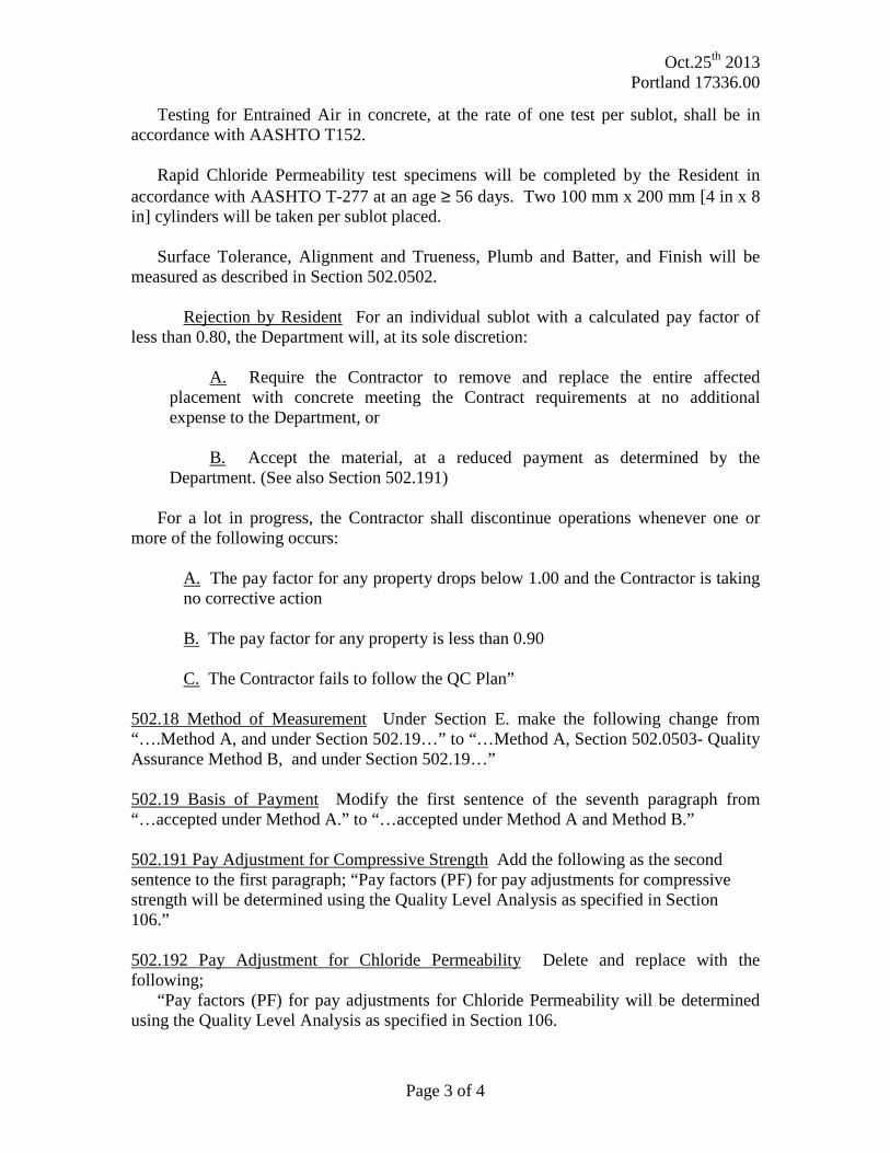
Testing for Entrained Air in concrete, at the rate of one test per sublot, shall be in accordance with AASHTO T152. Rapid Chloride Permeability test specimens will be completed by the Resident in accordance with AASHTO T-277 at an age ≥ 56 days. Two 100 mm x 200 mm [4 in x 8 in] cylinders will be taken per sublot placed. Surface Tolerance, Alignment and Trueness, Plumb and Batter, and Finish will be measured as described in Section 502.0502. Rejection by Resident For an individual sublot with a calculated pay factor of less than 0.80, the Department will, at its sole discretion:
A. Require the Contractor to remove and replace the entire affected
placement with concrete meeting the Contract requirements at no additional expense to the Department, or
B. Accept the material, at a reduced payment as determined by the
Department. (See also Section 502.191) For a lot in progress, the Contractor shall discontinue operations whenever one or more of the following occurs:
A. The pay factor for any property drops below 1.00 and the Contractor is taking no corrective action
B. The pay factor for any property is less than 0.90 C. The Contractor fails to follow the QC Plan” 502.18 Method of Measurement Under Section E. make the following change from “….Method A, and under Section 502.19…” to “…Method A, Section 502.0503- Quality Assurance Method B, and under Section 502.19…” 502.19 Basis of Payment Modify the first sentence of the seventh paragraph from “…accepted under Method A.” to “…accepted under Method A and Method B.” 502.191 Pay Adjustment for Compressive Strength Add the following as the second sentence to the first paragraph; “Pay factors (PF) for pay adjustments for compressive strength will be determined using the Quality Level Analysis as specified in Section 106.” 502.192 Pay Adjustment for Chloride Permeability Delete and replace with the following; “Pay factors (PF) for pay adjustments for Chloride Permeability will be determined using the Quality Level Analysis as specified in Section 106.

Oct.25th 2013 Portland 17336.00
Page 4 of 4
Values greater than 4000 coulombs shall be subject to rejection and replacement at no additional cost to the Department.” 502.193 Pay Adjustment for Air Content Delete and replace with the following; “ Pay factors (PF) for pay adjustments for air content will be determined using the Quality Level Analysis as specified in Section 106.” Add the following Section; “502.195 Pay Adjustments for Compressive Strength, Chloride Permeability and Air Content The Composite Pay Factor (CPF) for each lot of concrete shall be computed as follows: CPF = [(Compressive Strength PF-1)(0.20)] + [(Air Content PF-1)(0.40)] + [(Chloride Permeability PF-1)(0.40)] The pay adjustment for each lot of concrete shall be computed as follows: Lot Pay Adjustment = P x CPF x Lot Size There will be no positive pay adjustments for Method B Concrete.”

Portland Exit 5 Improvements at Thompson’s Point EDA Award #01-01-14202 Multi-WIN Rev. November 1, 2013
SPECIAL PROVISIONS SECTION 621 LANDSCAPE
(Plant Species Specification and Quantities List)
The following list of items provides the estimated quantities for use on this project. The scientific name of the plant material is provided along with the common name in parenthesis.
The contractor shall follow MDOT Standard Specifications (Dec 2002) for landscape materials and installation procedures (sec. 621).
In accordance with Section 104.5.9, a separate Performance Bond will not be required for the Landscape portion of this contract. A Maintenance Bond for a Two-Year Establishment period in the full value of the planting shall be included in this project.
The MDOT Landscape Architect or his designee will be available to inspect plant materials and stake the location of plant materials at the time of planting.
ITEM. Description Quan 18394.10 Thompson’s/Sewall Street 18394.10
18394.00 Thompson’s Point Conn. 18394.00 17336.00 Path 17336.00 Total
621.031 Evergreen Trees 4’ - 5’ B&B Group A 48 Thuja occ ‘Nigra Green’ (Dark Green Arb.) 12 Larix decidua (Eastern Larch) 36
621.279 Med. Dec Trees 2 1/2” – 3”cal .B&B Gr.A 6 Malus ‘Snowdrift’ (Snowdrift Crabapple) 6 621.2021 Med. Dec Trees 2 1/2” – 3”cal .B&B Gr.B 6 Syringa ret. ‘Ivory Silk’ (Jap. Tree Lilac) 6 621.281 Large Decid. Trees 2 1/2” - 3” calB&B Gr.C 40 Ginkgo biloba ‘Princeton Sentry’ (Ginkgo) 3 3 Quercus bicolor (Swamp White Oak) 1 24 12 37 621.389 Dwf.Evergreen Shrubs 15” – 18” Gr. A 84 Juniperus wiltoni (Wiltoni Juniper) 24 60 621.396 Dwf. Evergreen Shrubs 18” – 24” Cont. 148 Juniperus pfitziana compacta (Juniper) 24 124 621.403 Dwf.Evergreen Shrubs 2.5’ – 3’ Gr. A 6 Thuja Woodwardi (Globe Arborvitae) 6 621.494 Broadleef Evergreens 2’ – 2.5’ Group C 24 Rhododendron PJM ‘Scintillation’ 24 621.546 Deciduous Shrubs 2’ – 3’ Group A 12 Forsythia ‘ Meadowlark’ (Forsythia) 6 12 621.710 Herbaceous Perennials 1 Gal. Cont. 240 Hemerocallis ‘Happy Returns’ 60 60 Calamagrostis ‘Karl Foerster’ 12 60 Heme. Hyperion/Hap. Returns/ApricotSpar. 12 60 Panicum ‘Heavy Metal’ 12 60 621.80 Establishment Period Two-Year LS LS LS 1

Page 1 of 9
SPECIAL PROVISION
SECTION 635
PRECAST AGGREGATE-FILLED, CONCRETE BLOCK GRAVITY WALL
The following replaces Section 635 in the Standard Specifications in its entirety:
635.01 Description The work under this item shall consist of the design, fabrication,
furnishing and construction of a Precast Aggregate-filled Concrete Block Gravity Wall in
accordance with these specifications and in conformance with the lines and grades shown on the
Plans, or established by the Resident. The Precast Aggregate-filled Concrete Block Gravity Wall
shall consist of blocks made of Structural Precast concrete made from Portland cement, water,
chemical admixtures, and aggregates, supported on concrete leveling pads, and if required,
geosynthetic reinforced backfill.
Included in the scope of the precast gravity wall construction are: geotechnical design of any
wall with an exposed height greater than 4.5 ft or as specified on the Plans, all grading necessary
for wall construction, compaction of the wall foundation soil, backfill, piped drainage, construction
of leveling pads, and concrete wall unit installation. The top of the upper row of concrete wall
units shall be at or above the top of the face elevation shown on the Plans.
635.02 Quality Assurance The wall system shall be one of the approved combinations of
facing block and soil reinforcement systems noted in the Plans or on the Department’s Qualified
Products List (QPL). Alternate wall systems will not be considered for this Item.
All design calculations and Shop Drawings shall be signed and sealed by a Professional
Engineer licensed in the State of Maine.
The Contractor shall require the wall design-supplier to provide an on-site, qualified
experienced technical representative to advise the Contractor concerning proper installation
procedures. The technical representative shall be on-site during initial stages of installation and
thereafter shall remain available for consultation as necessary for the Contractor or as required by
the Resident.
635.03 Materials Materials for walls shall meet the requirements of the following sections of
Division 700:
Gravel Borrow 703.20
Underdrain Backfill Type C 703.22
Underdrain Pipe 706.06 or 706.09
Reinforcing Steel 709.01
Structural Precast Concrete Units 712.061
Reinforcement Geotextile 722.01
Drainage Geosynthetic 722.02
The Contractor is cautioned that all of the materials listed are not required for every Precast
Aggregate-filled Concrete Block Gravity Wall. The Contractor shall furnish the Resident a
Materials Certification Letter certifying that the applicable materials comply with this section of
the specifications. Materials shall meet the following additional requirements:

Page 2 of 9
635.031 Concrete Units The Materials Certification Letter described above shall contain the
date of concrete casting, a lot identification number, compressive strength results, and entrained air
results. All prefabricated concrete units shall conform to the requirements of 712.061 with the
following exceptions:
A. Materials. Materials are modified as follows: the maximum water cement ratio shall be
0.42, use of calcium nitrite is not required unless the design of the concrete wall units requires
fabrication with reinforcing steel, the minimum 28 day compressive strength shall be 4600 psi.
B. Quality Control and Quality Assurance. Quality Control and Quality Assurance is modified
as follows: delete the second paragraph.
C. Construction. Construction requirements are modified as follows:
Replace the first sentence in the paragraph which begins “Forms shall remain …” with
the following:
The forms shall remain in place until the concrete has gained sufficient strength such
that removal of the forms and subsequent handling will not damage the units.
Add the following paragraph at the end of the Construction section:
Face texture of the units shall be a formed finish on all exposed surfaces. Pigment shall
be added during the casting process of the concrete unit to achieve a consistent shade of
gray or other color as determined by the Resident.
D. Concrete Testing. The concrete testing requirements are modified as follows:
Replace the paragraph which begins “The Contractor shall cast a minimum of 8 ….”
With the following:
The Contractor shall make and test at least one set of cylinders for every 50 CY of
production concrete used to cast the concrete units.
Replace the paragraph which begins “At least once …” with the following:
The Contractor shall make four cylinders for use by the Department to represent every
200 CY or fraction thereof.
E. Tolerances. Maximum dimensional deviation of formed unit dimensions shall not vary
more than ½-inch or 2 percent of the unit dimension or the manufacturer’s published
tolerances, whichever is less. All units not meeting the specified tolerances will be
rejected.
635.032 Geosynthetic Reinforcement Geosynthetic Reinforcement shall be as required by the
proprietary wall system manufacturer or wall designer. Geosynthetic reinforcement shall consist of
a geotextile or geogrid approved by the Geotechnical Engineer. Substitution of a geosynthetic
other than that required by the proprietary wall system manufacturer shall not be allowed unless
approved by the Geotechnical Engineer after submittal of shop drawings and pullout and interface
friction test data.
A. Geotextiles and Thread for Sewing. Woven or nonwoven geotextiles shall consist of long
chain polymeric filaments or yarns formed into a stable network such that the filaments or
yarns retain their position relative to each other during handling, placement, and design
life. At least 95 percent by weight of the long chain polymer shall be polyolefin or
polyester. The material shall be free of defects and tears. Geotextiles used for

Page 3 of 9
reinforcement shall conform as a minimum to the properties indicated for 722.01,
Stabilization/Reinforcement Geotextile and shall meet the requirements of part D and E
below. Geotextiles shall have a minimum permeability greater or equal to that shown on
the Shop Drawings and the reinforced soil permeability.
B. Geogrids. The geogrid shall be a regular network of integrally connected polymer tensile
elements with aperture geometry sufficient to permit significant mechanical interlock with
the surrounding soil or rock. The geogrid structure shall be dimensionally stable and able
to retain its geometry under manufacture, transport and installation. Geogrids shall
conform as a minimum to the criteria specified in part D and E below.
C. Required Properties. The specific geosynthetic materials shall be preapproved and shall
the have the ultimate tensile strength (Tult) shown on the approved Shop Drawings for the
geosynthetic specified and for the fill type shown. Tult shall be determined from wide
width tests specified in ASTM D 4595 for geotextiles and ASTM D 6637 or GRI:GG1 for
geogrids. The ultimate tensile strength value is based on the minimum average roll values
(MARV) for the product.
D. The geosynthetic shall conform to the following criteria:
1. PP and HDPE: Min. retained strength of 70 percent after 150 hours, per ASTM D-
4355.
2. HDPE: Grade = E-4, E-5, E-8, E-9, E-10, E-11, J-3, J-4, or J-5, per ASTM D-1248.
3. PET: Molecular weight (Mn) > 25,000, per GRI:GG8 and ASTM D-4603.
4. PET: Carboxyl end group (CEG) ≥ 15 mmol/kg, GRI:GG7.
5. All polymers: Minimum Weight per Unit Area of 8 oz/yd2, per ASTM D-5261.
6. All Polymers: Maximum 0 percent post consumer recycled material by weight.
7. A default total reduction factor for creep, durability, and installation damage of RF
= 7 may be used in design, provided the criteria of 2 through 6 are satisfied and 1 is
adjusted to 70 percent after 500 hours is satisfied.
E. Manufacturer Quality Control. The geosynthetic reinforcements shall be manufactured
with a high degree of quality control. The Manufacturer is responsible for establishing and
maintaining a quality control program to ensure compliance with the requirements of the
specification. The purpose of the QC testing program is to verify that the reinforcement
geosynthetic being supplied to the project is representative of the material used for
performance testing and approval. Conformance testing shall be performed as part of the
manufacturing process and may vary for each type of product. As a minimum the
following index tests shall be considered as applicable for an acceptable QA/QC program:
Property Test Procedure
1. Specific Gravity (HDPE only) ASTM D-1505
2. Ultimate Tensile Strength ASTM D-4595 GRI:GG1
3. Melt Flow (HDPE and PP only) ASTM D-1238
4. Intrinsic Viscosity (PET only) ASTM D-4603
5. Carboxyl End Group (PET only) ASTM D-2455
F. Sampling Testing and Acceptance. Sampling and conformance testing shall be in
accordance with ASTM D-4354. Conformance testing procedures are established above.
Geosynthetic product acceptance shall be based on ASTM D-4759. The quality control
certificate shall include:

Page 4 of 9
1. Roll numbers and identification
2. Sampling procedures
3. Results of quality control tests, including a description of test methods used.
G. Certification. The Contractor shall submit a manufacturer’s certification that the
geosynthetics supplied meet the respective index criteria set when the geosynthetic was
approved, measured in full accordance with all test methods and standards specified, or
referenced, in this specification.
The manufacturer’s certificate shall state that the furnished geosynthetic meets the
requirements of these specifications as evaluated by the manufacturer’s quality control
program. The values submitted shall be certified by a person having legal authority to bond
the manufacturer. In case of dispute over validity of values, the Resident can require the
Contractor to supply test data from an agency approved laboratory to support the values
submitted, at the Contractor’s cost.
635.033 Concrete Leveling Pad Concrete for leveling pads shall be Fill Concrete conforming
to the requirements of Section 502 Structural Concrete. Unless otherwise specified, concrete for
leveling pads shall be accepted under Method “C” requirements.
635.034 Drainage Stone Fill Concrete wall unit voids shall be filled with drainage stone
material that conforms to the requirements of 703.22, Underdrain Backfill Material, Type C.
635.035 Backfill Material Backfill material placed behind the concrete wall units shall meet
the requirements of Section 703.20 Gravel Borrow, except that the backfill material shall only
contain particles that will pass the 3-inch square mesh sieve. The contractor is required to submit a
grain size distribution curve (ASTM D 422) and a moisture-density relationship curve (AASHTO
T-180) for acceptance of the proposed backfill material and determination of the appropriate
installation damage reduction factor (RFID).
Walls with reinforced backfill also require that the backfill material be subjected to pH testing
to determine the appropriate durability reduction factor (RFD).
635.036 Materials Certificate Letter The Contractor, or the supplier as their agent, shall
furnish the Resident a Materials Certificate Letter for the above materials, including the backfill
material, in accordance with Section 700 of the Standard Specifications. A copy of all test results
performed by the Contractor or their supplier necessary to assure contract compliance shall also be
furnished to the Resident. The Resident will base acceptance upon the materials Certificate Letter,
accompanying test reports, and visual inspection.
635.04 Design Requirements The wall shall be designed with a service life of not less than 75
years. The Precast Aggregate-filled Concrete Block Gravity Wall shall be designed and sealed by
a Professional Engineer licensed in the State of Maine. The wall shall be designed in accordance
with the following:
1. AASHTO LRFD Bridge Design Specifications, current edition, herein referred to as LRFD
2. FHWA-NHI-10-024 and FHWA-NHI-025 Design and Construction of Mechanically
Stabilized Earth Walls and Reinforced Soil Slopes, Volume I and II, 2009

Page 5 of 9
3. FHWA-NHI-09-087 Corrosion/Degradation of Soil Reinforcements for Mechanically
Stabilized Earth Walls and Reinforced Soil Slopes, 2009
4. The Contract Plans
5. The requirements specified herein
6. The manufacturer’s requirements
Where conflicting requirements occur, the more stringent requirements shall govern.
Forty-five days prior to beginning construction of the wall, the design computations shall be
submitted to the Resident for review by the Geotechnical Engineer. Any additional design or costs
arising as a result of rejection of a wall design by the Geotechnical Engineer shall be borne by the
Contractor.
Design calculations that consist of computer program generated output shall be supplemented
with at least one hand calculation and graphic demonstrating the design methodology used. Design
calculations shall provide thorough documentation of the sources of equations used and material
properties. The design by the wall system supplier shall consider the stability of the wall as
outlined below and in the Contract Documents:
A. Failure Plane The theoretical failure plane within the reinforced soil mass shall be
determined in accordance with LRFD Article 11 and be analyzed so that the soil stabilizing
components extend sufficiently beyond the failure plane within the reinforced soil mass to
stabilize the material.
B. External Loads External loads which affect the internal and external stability such as those
applied through traffic loadings, impact on traffic barrier posts, slope surcharge, hydrostatic,
and seismic loads shall be accounted for in the design. Traffic surcharge and traffic impact
loads shall be calculated and applied in compliance with LRFD Section 11.
C. External Stability Loads and load combinations selected for design shall be consistent with
LRFD. Application of load factors shall be taken as specified in LRFD Section 11. Sliding
resistance factors and bearing resistance factors shall be consistent with LRFD.
Overturning and sliding provisions of LRFD shall apply.
D. Internal Stability Evaluation of reinforcement pullout, reinforcement rupture and
reinforcement/block connection pullout or rupture shall be consistent with LRFD Section
11, and checked at each level. Loads, load combinations and load factors shall be as
specified in LRFD Section 11. Resistance factors for internal design are specified in LRFD
Section 11. Maximum reinforcement loads shall be calculated using the Simplified Method
approach. Calculations for factored stresses and resistances shall be based upon assumed
conditions at the end of the design life.
a. Geosynthetic Reinforcement Design Tensile Resistance The nominal long
term reinforcement design strength (Tal) shall be determined by reducing Tult
by reduction factors (RF) in accordance with the documents referenced above.
The designer shall procure and use the manufacturers tested and certified
geosynthetic reinforcement reduction factors for creep (RFCR), durability
(RFD), and installation damage (RFID) to determine Tal. In absence of
manufacturers tested and certified reduction factors, a combined default
reduction factor RF = 7 shall be used in accordance with the referenced

Page 6 of 9
documents. For RFID, the installation damage reduction factor shall be
checked in accordance with LRFD and FHWA-NHI-00-044.
b. Reinforcement/Facing Connection Design Strength The nominal long-term
connection strength between the geosynthetic reinforcement and the concrete
blocks shall be checked in accordance with LRFD and FHWA-NHI-00-043.
c. Reinforcement Pullout The pullout resistance factor, (F*), and scale effect
correction factor (α) used in pullout design, shall be determined from project
specific pullout tests using the proposed geosynthetic in the specified project
backfill material or equivalent soil. The pullout resistance factors shall be
determined in accordance with LRFD and FHWA-NHI-00-043. In the absence
of test data, empirical relationships may be used to determine the pullout
resistance factors, any empirical relationships used in design shall be
referenced in the design calculations.
E. Backfill and Foundation Soils Parameters The friction angle of the backfill used in the
reinforced fill zone for internal stability design shall be assumed have a friction angle of 34
degrees unless specific project select backfill is tested for frictional strength. The friction
angle of the foundation soils and random backfill shall be assumed to be 30 degrees unless
otherwise shown on the plans.
F. Reinforcement Length The soil reinforcement shall be the same length from the bottom to
the top of each wall section. The reinforcement length defining the width of the entire
reinforced soil mass may vary with wall height. The minimum length of the soil
reinforcement shall be 8 ft, but shall not be less than 70 percent of the wall height, H, for
walls with level surcharges, or 70 percent of H1 for walls with a sloped surcharge or walls
supporting an abutment. The mechanical wall height, H or H1, shall be the vertical
difference between the top of the leveling footing and the elevation at which the failure
surface, as described above, intercepts the ground surface supported by the wall.
G. Bearing Resistance The factored bearing pressures under the Precast Aggregate-filled
Concrete Block Gravity Wall shall be clearly indicated on the Shop Drawings. Walls shall
be dimensioned so that the factored bearing resistance of the foundation soils, as noted on
the Plans, is not exceeded.
H. Facing Stability Stability calculations for the concrete facing blocks shall be in accordance
with LRFD, and shall include an evaluation of the maximum vertical spacing between
reinforcement layers.
I. Stability During Construction Walls shall be designed to resist failure by instability of
temporary construction slope. Passive pressure in front of the wall mass shall be assumed
to be zero for design purposes.
J. Design Life The wall design life shall be a minimum of 75 years.
K. Depth of Embedment The depth of embedment for frost protection and stability shall be at
or below the elevation shown on the Plans and the approved Shop Drawings.

Page 7 of 9
L. Drainage System Piped drainage shall be designed to collect and dispose of water from the
base of the reinforced soil zone and backfill soil. This shall outlet into surrounding
drainage systems or ditches.
635.05 Submittals. The Contractor shall supply wall design computations, wall details,
dimensions, quantities, and cross sections necessary to construct the wall. A sample hand
calculation including all equations, parameter values used, units, theory, free-body diagram,
comparison to design requirements, etc. shall be provided. Spreadsheet calculations alone are not
acceptable.
Forty-five (45) days prior to beginning construction of the wall, four (4) sets of the wall design
computations and Shop Drawings shall be submitted to the Resident for review by the
Geotechnical Engineer. Mix design information shall be submitted at the same time, including
aggregate source, current gradation, aggregate quality information and concrete unit weight.
The contractor shall also submit backfill material test results as part of the wall submittal package.
Backfill material test results shall include grain size distribution curve, moisture-density
relationship curve, and pH test results required for reinforced backfill only.
If geotechnical design is required, the fully detailed plans shall be prepared in conformance with
Section 105 and shall include, but not be limited to the following items:
A. A plan and elevation sheet or sheets for each wall, containing the following: elevations at
the top of leveling pads, the distance along the face of the wall to all steps in the leveling
pads, the location of the original and final ground line.
B. All details for foundations and leveling pads, including details for steps in the leveling
pads, as well as allowable and actual maximum bearing pressures shall be provided.
C. Details for the barriers, posts, curbs and facing as required by the project conditions.
D. Design computations prepared and sealed by a licensed Professional Engineer.
E. Prior to the beginning of construction, the contractor shall supply the Resident with two
copies of the design-supplier’s Installation Manual. In addition, the Contractor shall have
two copies of the Installation Manual on the project site.
635.06 Construction Requirements The Precast Aggregate-Filled Concrete Block Gravity
Wall shall have the following construction requirements:
A. Excavation. The excavation and use as fill or disposal of all excavated material shall meet
the requirements of Section 203 - Excavation and Embankment, except as modified herein.
B. Foundation. The area upon which the prefabricated, aggregate-filled concrete block gravity
wall structure is to rest, and within the limits shown on the submitted plans, shall be graded
for a width equal to, or exceeding, the length of the blocks. Prior to wall and leveling pad
construction, this foundation material shall be compacted to at least 95 percent of
maximum laboratory dry density (AASHTO T-180 Method C or D). Frozen and unsuitable
soil shall be removed and replaced with gravel borrow compacted to 95 percent of
AASHTO T-180, or as shown on the plans.

Page 8 of 9
A concrete leveling pad shall be constructed a minimum of 6 inches beyond the front and
back of the concrete wall units, or as indicated on the plans. Dimensions may be modified
per the wall supplier’s recommendations, with written approval of the Geotechnical
Engineer. The leveling pad shall be cast to the design elevations as shown on the plans, or
as required by the wall supplier upon written approval of the Geotechnical Engineer.
The allowable elevation tolerances from the design elevations are +0.01 ft and -0.02 ft.
Leveling pads which do not meet this requirement shall be repaired or replaced as directed
by the Resident at no additional cost to the Department. Placement of wall units may begin
after the strength of the concrete leveling pad reaches 1000 psi or is adequate to support the
proposed loads. Contractor may begin placement of concrete block units after 12 hours at
their own risk.
C. Method and Equipment. Prior to erection of the wall, the Contractor shall furnish the
Resident with detailed information concerning the proposed construction method and
equipment to be used. The erection procedure shall be in accordance with the
manufacturer’s instructions. Any units that are damaged due to handling will be replaced
at the Contractor’s expense.
D. Installation of Concrete Wall Units. A field representative from the wall system being used
shall be available, as needed, during the erection of the wall. The services of the
representative shall be at no additional cost to the project.
The contractor shall place the first course of wall units directly on the leveling pad and
check for level and alignment. Adjacent units should be in contact. The prefabricated
concrete wall units shall be installed to a tolerance of plus or minus 3/4 inch in 10 ft in
vertical and horizontal alignment.
Fill all voids between and within the wall units with drainage stone as described in this
specification. The drainage stone fill shall extend a minimum of 6 in behind the tails of the
wall units unless a geotextile filter is placed over the inside joint at the back of adjacent
wall units. If used, the drainage geotextile shall conform to the requirements of Section
722.02.
E. Backfill Placement. Backfill placement shall closely follow the erection of each row of
prefabricated wall units. The maximum lift thickness shall be 8 inches loose. The
Contractor shall decrease the lift thickness if necessary to obtain the specified density. The
backfill shall be compacted in accordance with Section 203.12 except that the minimum
required compaction shall be at least 92 percent of maximum density as determined by
AASHTO T-180 Method C or D. Backfill compaction shall be accomplished without
disturbance or displacement of the concrete wall units. Sheepsfoot rollers will not be
allowed. Whenever a compaction test fails, no additional backfill shall be placed over the
area until the lift is recompacted and a passing test achieved.
The moisture content of the backfill material prior to and during compaction shall be
uniform throughout each layer. Backfill material shall have a placement moisture content
less than or equal to the optimum moisture content. Backfill material with placement
moisture content in excess of the optimum moisture content shall be removed and
reworked until the moisture content is uniform and acceptable throughout the entire lift.

Page 9 of 9
The optimum moisture content shall be determined in accordance with AASHTO T-180,
Method C or D. At the end of the day’s operations, the Contractor shall shape the last level
of backfill so as to direct runoff of rainwater away from the wall face.
635.07 Method of Measurement Precast Aggregate-filled Concrete Block Gravity Wall will
be measured by the square foot of front surface not to exceed the dimensions shown on the
Contract Plans unless authorized by the Resident. Vertical and horizontal dimensions will be from
the edges of the blocks. No field measurements for computations will be made unless the Resident
specifies, in writing, a change in the limits indicated on the Plans.
635.08 Basis of Payment The accepted quantity of Precast Aggregate-Filled Concrete Block
Gravity Wall will be paid for at the contract unit price per square foot complete in place. Payment
shall be full compensation for furnishing geotechnical design as required, all labor, equipment and
materials including all precast concrete units, hardware, joint fillers, geosynthetic, drainage pipe,
and technical field representative.
Cost of cast-in-place concrete for leveling pad will not be paid for separately, but will be
considered incidental to the Precast Aggregate-Filled Concrete Block Gravity Wall. Excavation,
foundation material and backfill material will all be incidental to the Precast Aggregate-Filled
Concrete Block Gravity Wall.
There will be no allowance for excavating and backfilling for the Precast Aggregate-Filled
Concrete Block Gravity Wall beyond the limits shown on the approved submitted plans, except for
excavation required to remove unsuitable subsoil in preparation for the foundation. Payment for
excavating unsuitable subsoil shall be full compensation for all costs of pumping, drainage,
sheeting, bracing and incidentals for proper execution of the work, and will be paid as common
excavation in accordance with Section 203.
Payment will be made under:
Pay Item Pay Unit
635.40 Precast Aggregate-Filled Concrete Block Gravity Wall Square Foot

ENGINEERS
Existing Trail Conditions The Forefront at Thompson’s Point
Photos Taken 08.09.13 by Bo Kennedy, P.E.
FAY, SPOFFORD & THORNDIKE 778 Main Street, Suite 8 South Portland, ME 04106 Toll Free: 800.835.8666 Main: 207.775.1121 Fax: 207.879.0896
PHOTO 1 – Shows existing trail at Sta. 23+00± looking southerly. Contractor shall remove existing crib wall on the right and protect existing trees.
PHOTO 2 – Shows existing crib wall at Sta. 23+25±

ENGINEERS
Existing Trail Conditions The Forefront at Thompson’s Point
Photos Taken 08.09.13 by Bo Kennedy, P.E.
FAY, SPOFFORD & THORNDIKE 778 Main Street, Suite 8 South Portland, ME 04106 Toll Free: 800.835.8666 Main: 207.775.1121 Fax: 207.879.0896
R:\2982.05 Amended Site Plan Part II\Admin\Construction\RFI\Existing Trail Photos.doc
PHOTO 3 – Shows existing crib wall at Sta. 23+25±


![2001SPECIFICATIONS PAY ITEM INDEX1].pdf · 2001specifications date: 2/12/2013 pay item index reduction of pay and emergency maintenance item no. units ls units description 0002-0002](https://static.documents.pub/doc/80x56/5a9843be7f8b9a9c5b8d5c0f/2001specifications-pay-item-1pdf2001specifications-date-2122013-pay-item-index.jpg)


