IN THIS ISSUE VOLUME 27, ISSUE 9 JULY 2014 INDUSTRY NEWS & DEVELOPMENTS By Vance Dickason PRODUCTS & SERVICES TEST BENCH A Mini Home Full-Range Driver and a Pro Sound Coaxial By Vance Dickason 1 Industry News & Developments By Vance Dickason 5 through 1 p.m. on Saturday, July 19. The Top 10 Fastest Hands and Top 10 Fastest Feet will then compete in “finals battles” on Saturday, July 19, at 2 p.m. Contestants should sign in at the World’s Fastest Drummer Contest stage area located at the Music City Center’s Level 3, A1 Lobby starting the morning of Thursday, July 17. Also on Thursday, July 17, a panel discussion entitled “Insight: Hard-Earned Wisdom from Industry Icons,” moderated by country music legend Vince Gill and Two Old Hippies’ Tom Bedell, will take place in the Davidson Ballroom. For more information, visit www.namm.org. Summer NAMM 2014—Nashville 2.0 The 2014 Summer National Association of Music Merchants (NAMM) show is being held at the Music City Center, a state-of-the-art convention center in Nashville, TN, from July 17–19, 2014 (see Photo 1). This is the second year Summer NAMM will take place in the new convention center, hence the Nashville 2.0 designation. Summer NAMM organizers are hoping to keep attendance momentum growing in 2014. Summer NAMM 2012 saw a 20% increase in attendance, and a 9% increase in exhibitors (372 total) over the 2011 show. Summer NAMM 2013 had 11,498 in attendance, up only 12% from 2012. While attendance at Winter NAMM was healthy with 93,908 attendees in 2013, Summer NAMM has struggled. Hopefully, it won’t go the way of the Summer Consumer Economic Show (CES). One of the highlights of the 2014 Summer NAMM show is the return of the “World’s Fastest Drummer” contest. The contest, which consists of two categories— “Fastest Hands” and “Fastest Feet”—will be held each day on the World’s Fastest Drummer stage, starting at 11 a.m. on Thursday, July 17. The “heats” will continue ACOUSTIC PATENTS By James Croft INDUSTRY WATCH By Vance Dickason 12 29 Photo 1: The 2013 Summer National Association of Music Merchants (NAMM) show attracted 11,498 attendees. 24
Transcript
IN THIS ISSUE
V O L U M E 2 7 , I S S U E 9 J U L Y 2 0 1 4
INDUSTRY NEWS & DEVELOPMENTSBy Vance Dickason
PRODUCTS & SERVICES
TEST BENCH A Mini Home Full-Range Driver and a Pro Sound CoaxialBy Vance Dickason
1
Industry News & DevelopmentsBy Vance Dickason
5
through 1 p.m. on Saturday, July 19. The Top 10 Fastest Hands and Top 10 Fastest Feet will then compete in “finals battles” on Saturday, July 19, at 2 p.m.
Contestants should sign in at the World’s Fastest Drummer Contest stage area located at the Music City Center’s Level 3, A1 Lobby starting the morning of Thursday, July 17. Also on Thursday, July 17, a panel discussion entitled “Insight: Hard-Earned Wisdom from Industry Icons,” moderated by country music legend Vince Gill and Two Old Hippies’ Tom Bedell, will take place in the Davidson Ballroom. For more information, visit www.namm.org.
Summer NAMM 2014—Nashville 2.0The 2014 Summer National Association of Music
Merchants (NAMM) show is being held at the Music City Center, a state-of-the-art convention center in Nashville, TN, from July 17–19, 2014 (see Photo 1). This is the second year Summer NAMM will take place in the new convention center, hence the Nashville 2.0 designation.
Summer NAMM organizers are hoping to keep attendance momentum growing in 2014. Summer NAMM 2012 saw a 20% increase in attendance, and a 9% increase in exhibitors (372 total) over the 2011 show. Summer NAMM 2013 had 11,498 in attendance, up only 12% from 2012. While attendance at Winter NAMM was healthy with 93,908 attendees in 2013, Summer NAMM has struggled. Hopefully, it won’t go the way of the Summer Consumer Economic Show (CES).
One of the highlights of the 2014 Summer NAMM show is the return of the “World’s Fastest Drummer” contest. The contest, which consists of two categories—“Fastest Hands” and “Fastest Feet”—will be held each day on the World’s Fastest Drummer stage, starting at 11 a.m. on Thursday, July 17. The “heats” will continue
ACOUSTIC PATENTSBy James Croft
INDUSTRY WATCH By Vance Dickason
12
29
Photo 1: The 2013 Summer National Association of Music Merchants (NAMM) show attracted 11,498 attendees.
Voice Coil, (ISSN 1521-091X), The Periodical for the Loudspeaker Industry, is published monthly by Segment, LLC, 111 Founders Plaza, Suite 300, East Hartford, CT 06108 US, (860) 289-0800, FAX (860) 461-0450.
Head Office: Segment LLC111 Founders Plaza, Suite 300, East Hartford, CT 06108Phone: (860) 289-0800
Subscriptions: Subscriptions to Voice Coil are available in printed and digital versions. To subscribe, please visit our website at voicecoilmagazine.com and complete a qualification form. Qualified subscriptions to Voice Coil run for one year. Renew annually on-line at voicecoilmagazine.com Address Changes/Problems: [email protected]
Postmaster: Send address changes to Voice Coil Circulation Dept., P.O. Box 462256, Escondido, CA 92046.
When you qualify, you will receive an e-mail confirming your subscription. The current issue of each digital Voice Coil will be posted to gotomyvcoil.com at the end of the month. To access, use the link in the e-mail notification, or you can simply log in to the website to view your issue along with the archived issues.
For those overseas, the cost of a printed subscription is $150.00 per year. Please contact customer service or order your subscription online at voicecoilmagazine.com.
Not a member yet?Subscribe at voicecoilmagazine.com
US Advertising: Strategic Media Marketing, Inc.2 Main St., Gloucester, MA 01930 USPhone: (978) 281-7708Fax: (978) 281-7706, e-mail: [email protected]
Advertising rates and terms available on request. E-mail Kiki Donaldson with artwork inquiries at: [email protected].
Editorial Inquiries:Send all press releases and information to Voice Coil, Segment, LLC Editorial Dept., 111 Founders Plaza, Suite 300, East Hartford, CT 06108, FAX us material at (860) 461-0450, or e-mail [email protected].
Legal Notice:Copyright 2014 by Segment, LLC. All rights reserved. Quotation from Voice Coil is forbidden without written permission of the publisher.Printed in the United States
New Eminence Speakers for 2014Eminence introduced several new pro audio woofers,
musical instrument woofers, and compression drivers for 2014. The new offerings include the following pro audio drivers:
• The Delta Pro 12-450 is a lighter weight version of the Delta Pro 12. It is recommended as a woofer or midrabge/bass in vented enclosures. It also makes a perfect replacement in many portable PA cabinets.
• The Kappa Pro-10LF is an enhanced low-frequency version of the Kappa Pro 10. It excels in compact vented or horn-loaded bass guitar or subwoofer enclosures.
• The LA10850 is a high-power midrange driver in a shallow cast frame with an inverted dust cap for close placement to phase plugs, which are used in many horn-loaded designs. It is also suitable as a high-power midrange/bass driver in small conventional vented enclosures, or as a high-power midrange in compact sealed enclosures.
• The LA12850 is a high-power 12” woofer in a shallow cast frame designed to work in ultra-compact vented systems and enable tight packaging in line arrays or other systems where overall depth is limited.
• The LA15850 is a shallow 15” high-power cast frame woofer with a 4” voice coil and super-strong cone body. The inverted dust cap enables close placement to phase plugs, which are used in many horn-loaded designs.
• The Kappa Pro-15A is recommended for pro audio use in a vented mid-bass or bass enclosure. It is also suitable for bass guitars.
• The Kappa Pro-15B is a 16-Ω version of the popular Kappa Pro 15. It is recommended for pro audio use in a vented mid-bass or bass enclosure, and it is also suitable for bass guitars.
Eminence’s new compression drivers include:
• The PSD:2013-16/8 has a 1” throat, a titanium diaphragm, and a ferrite magnet.
• The PSD:3014-16/8 has a 1.4” throat, a titanium diaphragm, and a ferrite magnet.
Eminence’s new guitar speakers include:
• The 620H-8/4 is the little brother to the 820H. The 620H is a 4-Ω hemp cone speaker with a warm, full, and clean tone that will make a small, thin amplifier sound bigger and fatter.
• The CV-75 is a new addition to Eminence’s Red Coat series. It is described as the epitome of British tone with a complete tonal balance. The CV-75 offers grunt and punch in the low ranges, warm/tailored midranges, and nice, clear, open/airy high ranges.
• The Legend EM12 is a high-power 12” guitar speaker featuring an ultra-clean tone with big, round, punchy lows and warm, smooth midranges and high ranges.
• The Legend 1275 is a British-voiced speaker reminiscent of classic original equipment manufacturer (OEM) tones from the past with tight, punchy lows, warm midranges, and crisp, articulate, open high ranges.
• The GA-SC64 is an extension of the Eric Johnson Signature Series. The Vintage American ceramic magnet tone is approved by legendary amplifer builder George Alessandro. It is well-balanced from top to bottom with tight, full lows, warm midranges, and warm, but open high ranges.
For more information, visit www.eminence.com.
Bozhen New Audio Lab’s Speaker TechnologyVoice Coil featured a rather innovative and patented
ribbon tweeter from Bozhen New Audio Lab in its April
Photo 2: The DDQ prototype’s front (a), back (b), and horizontal (c) views are shown.
A New Paradigm Demands New Designs Save the dates! Saturday & Sunday, January 3 &4, 2015 at the Tuscany
Suites and Casino, Las Vegas, Nevada. Bigger! More to see! More to do! More quality! More networking! Better value than ever!
NEW! A separate track dedicated to the BUSINESS of electro-acoustics! Call for Speakers & Content
ALMA is accepting ideas and proposals for content for Winter Symposium for all subject matter related to the loudspeaker industry. Call or email proposals now!
Make your plan to be a part of the NEW ALMA! Get involved! 602-388-8669 or [email protected]
Tymphany LAT 500 and the Tymphany LAT 700 in Test Bench (April 2008 and June 2008).
The problem Bozhen New Audio Lab solved was how to apply the same transducer array principle found in the Tymphany LAT 500 and 700 using a flat baffle mounting configuration. One of the issues—if you want to call it that—with the LAT drivers was that it protruded out of the flat baffle mounting by a distance equal to approximately one-half of the diameter of the woofers used in the array. The Bozhen technology enables you to use a flat baffle mounting (see Photo 2).
Bozhen New Audio Lab describes the technology as a unique design that comprises the following parts:
Figure 1: The DDQ driver format’s structural cut-away view
Figure 2: The DDQ substructure view
2013 issue. The company, founded in Shenzhen, China, in 1995, recently sent me another patented loudspeaker it developed as the DDQ series. DDQ is the acronym in Chinese Pinyin for “Duolian Duichen Qudong,” which means multi-folded symmetrical driving technology. Its structure is completely different from traditional cone-type woofers.
However, its concept is similar to the Tymphany Linear Array Transducer (LAT). Voice Coil featured the
Model DDQ4.5-4 DDQ6.5-4
Frequency range 55–1,600 Hz ±3 db
45–1,300 Hz ±3 db
Sensitivity 87 dB at1 W/1 m
87 dB at 1 W/1 m
Impedance 8 Ω 8 Ω
F0 65 Hz ±10% 55 Hz ±10%
Rated power 50 W 50 VA
Dimension 33 cm × 20 cm × 15 cm
38 cm × 24 cm × 20 cm
Table 1: Specifications for Bozhen New Audio Labs’ two new prototype models
Legend (see Figures 1–3)
12345
FrameSurroundCone-ACone-BTransmission plate-A
67
Transmission plate-BTransmission pole A
8910
Transmission pole BSingle long poleDriver unit-A
11 Driver unit-B
12 Joint hole
13 Through hole
14 Side plate
15 Front installation panel
Figure 3: The transmission pole structure
20 Hz 50 100 200 500 1K 2K 5K 10K
Ohm
1
2
5
10
20
50
100
Impedance vs Freq
Figure 4: The black curve shows the impedance for DDQ4.5-4. The blue dash curve shows the impedance for the DDQ6.5-4.
20 Hz 50 100 200 500 1K 2K 5K 10K
dBSPL
55
60
65
70
75
80
85
90
95
SPL vs Freq
Figure 5: The black curve shows the DDQ Model 4.5’s on-axis frequency response. The blue dash cuve shows the DDQ Model 6.5’s on-axis frequency response.
• Several “V” type substructures that mainly comprise one framework and two cones
• Two symmetrical driving units installed on its two ends
• Two specially designed high-rigidity transmission poles that go through each “V” substructure’s center
• Two transmission poles that are separately driven by one driving unit each
• Each transmission pole drives one side cone in each “V” substructure that it goes through (i.e., if the DDQ has four “V” substructures, one transmission pole will simultaneously drive four cones
When the DDQ is operating, two symmetrical driving units push every “V”-type substructure’s cones by the transmission poles. These two cones in each “V”-type substructure then move in opposite directions. Through this motion, the air is pulled in or pushed out to produce sound. Figures 1–3 along with the legend illustrate the DDQ transducer’s construction.
The DDQ transducer’s specific features include:
• The DDQ’s low-end limit is F0. Notice its sound pressure level (SPL) has no rolloff on its F0 point. Usually, a traditional woofer has a typical 3 to 6-dB rolloff at its F0. Boshen New Audio Lab’s DDQ4.5-4
has a F0 at 65 Hz, its SPL has no rolloff at 65 Hz, and –3 dB at 55 Hz. Its DDQ6.5-4 has a F0 at 55 Hz, its SPL has no rolloff at 55 Hz, and –3 dB at 45 Hz.
• The DDQ adopts a symmetrical driving structure. The motion direction between the adjacent cone is opposite and has nearly zero resultant forces. When installed in the speaker box, it brings very slight vibration, so the bass quality is much purer.
• The DDQ has several “V”-type substructures. Each “V”-type substructure acts as a sound source when it works. Each “V”-type substructure has two cones driven by separate transmission poles. When it works, these two cones will pull in or push out the air to produce sound. Because this “V”-type structure has a particular compression ratio, the DDQ has almost no power compression in its low end.
Bozhen New Audio Labs has two prototype models available, the 4.5” based DDQ4.5-4, and the 6.5” based DDQ6.5-4. Table 1 lists the specifications for these two models.
Bozhen New Audio Labs provided measured data for both drivers. Figure 4 shows the impedance of both the 4.5” and 6.5” models. Figure 5 shows the on-axis frequency response of both models. For more information, visit www.bzspeakers.com. VC
profile brand names for over 20 years… experience that’s hard to find!
Vance Dickason Consulting has been developing award winning products for numerous high profile brand names for over 20 years… experience that’s hard to find!
With extensive experience in high-end off-wall, in-wall, on-wall, ceiling and subwoofer products plus close relationships with some of the worlds best speaker OEM’s and you have a combination of services that will accelerate your next product lineup.
We have all the best toys (Klippel, LEAP 5,LMS, CLIO, MLSSA, LSPCad, FEA), so whether its multimedia, car audio, MI, Pro, two-channel or Home Theater (including THX®), VDC has the solutions.
Add to that an available design team that includes some of the best transducers engineers, industrial designers and marketing experts I know of in the industry and you have a winning combination that would cost well over $750,000 a year to keep in house.
off an audioxpress membershipaudioxpress membershipaudioxpress
audioxpress.com/vcpJ O I N T O D A Y !J O I N T O D A Y !J O I N T O D A Y !J O I N T O D A Y !J O I N T O D A Y !J O I N T O D A Y !
acousticsaudio
audioXpress has been serving up the best in DIY audio for more
acousticsthan a decade! With an acousticsincreased focus on professional acousticsincreased focus on professional acousticsacousticsaudio, acoustics, and audio electronicsacousticsacoustics, acousticsaudioXpressacousticsaudioXpressacoustics is
expanding its coverage and content to better serve audiophiles
worldwide. Become a member and gain instant access to audioworldwide. Become a member and gain instant access to audiodesign tips, product reviews, and industry insight.audiodesign tips, product reviews, and industry insight.audio
diameter hole that forms a pole vent.I used the LinearX LMS analyzer and VIBox to create
voltage and admittance (current) curves with the PMT-40N25AL01-04 clamped to a rigid test fixture in free air at 0.3, 1, 3, and 6 V. I discarded the 6-V curves as
A Mini Home Full-Range Driver and a Pro Sound Coaxial
By Vance Dickason
This month’s transducers are from opposite ends of the driver spectrum: the PMT-40N25AL01-04, a 1”
full-range transducer from Tymphany Peerless, and the 12FCX76, a new 12” high-performance pro sound coaxial from B&C Speakers.
The PMT-40N25AL01-04The 1” diameter full-range drivers (e.g., Scan-Speak’s
2” 5F/8422T01, which was featured in Voice Coil’s October 2013 issue) are currently among the most used transducers in consumer electronics. They are finding broad use in numerous Bluetooth speakers (e.g., the Jambox Mini, Logitech’s UE-Boom, and the Beats Pill by Dr. Dre). The driver submitted by Tymphany Peerless this month fits into that category (see Photo 1).
The Peerless PMT-40N25AL01-04 is a 25-mm (1”) diameter full-range driver built on a proprietary injection-molded two-piece polycarbonate (one piece for the motor assembly structure and one piece for the protective grill). The cone assembly consists of one piece of inverted aluminum suspended with a foam surround that provides all the compliance (there is no spider mechanism). As with all the 1” long-throw inverted dome drivers on the market, it has a 26-mm diameter voice coil. This is wound with round copper wire on a polyimide (Kapton) former, terminated to opposite mounted solderable terminals. It also has magnetic fluid in the gap. Since it was not mentioned in the literature, I assume this is a low-viscosity fluid that does not impact the compliance.
A neodymium motor using a neodymium slug and a milled return cup drives the cone assembly. For cooling, the return cup, the neodymium slug, and a metal top plate separated from the slug by an insulated layer have a 5-mm
Test Bench
a)
b)
c)
10 Hz 20 50 100 200 500 1K
Sec
0
1m
2m
3m
4m
Time vs Freq
10 Hz 20 50 100 200 500 1K
dBSPL
50
55
60
65
70
75
80
85
90
95
100
SPL vs Freq
Figure 2: Peerless PMT-40N25AL01-04 computer box simulations (black solid = sealed at 2.83 V; blue dash = vented at 2.83 V; black solid = sealed at 4.2 V; blue dash = vented at 4.2 V)
Figure 3: Group delay curves for the 2.83-V curves in Figure 2
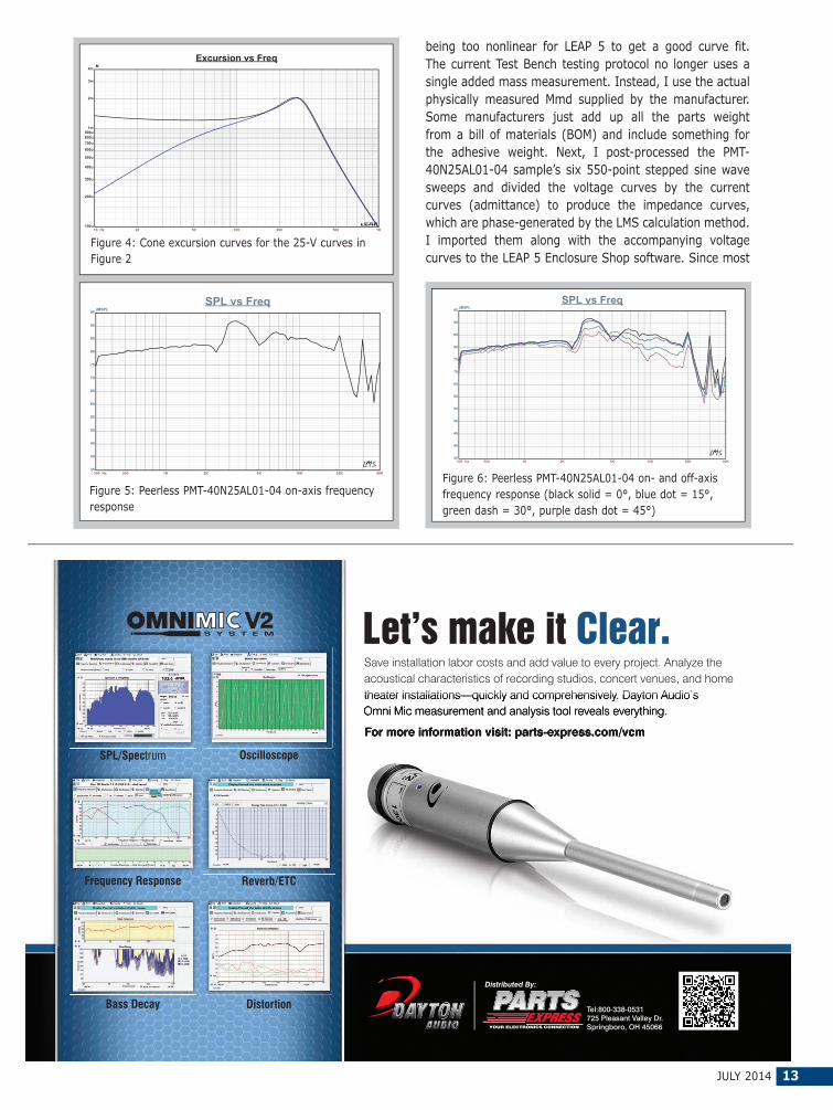
being too nonlinear for LEAP 5 to get a good curve fit. The current Test Bench testing protocol no longer uses a single added mass measurement. Instead, I use the actual physically measured Mmd supplied by the manufacturer. Some manufacturers just add up all the parts weight from a bill of materials (BOM) and include something for the adhesive weight. Next, I post-processed the PMT-40N25AL01-04 sample’s six 550-point stepped sine wave sweeps and divided the voltage curves by the current curves (admittance) to produce the impedance curves, which are phase-generated by the LMS calculation method. I imported them along with the accompanying voltage curves to the LEAP 5 Enclosure Shop software. Since most
300 Hz 500 1K 2K 5K 10K 20K 40K
dBSPL
35
40
45
50
55
60
65
70
75
80
85
90
95
SPL vs Freq
Figure 6: Peerless PMT-40N25AL01-04 on- and off-axis frequency response (black solid = 0°, blue dot = 15°, green dash = 30°, purple dash dot = 45°)
10 Hz 20 50 100 200 500 1K
M
100u
200u
300u
400u
500u
600u
700u800u900u
1m
2m
3m
4m
Excursion vs Freq
Figure 4: Cone excursion curves for the 25-V curves in Figure 2
300 Hz 500 1K 2K 5K 10K 20K 40K
dBSPL
35
40
45
50
55
60
65
70
75
80
85
90
95
SPL vs Freq
Figure 5: Peerless PMT-40N25AL01-04 on-axis frequency response
SPL/Spectrum Oscilloscope
Frequency Response Reverb/ETC
Bass Decay Distortion
For more information visit: parts-express.com/vcm
Let’s make it Clear.Save installation labor costs and add value to every project. Analyze the acoustical characteristics of recording studios, concert venues, and home theater installations—quickly and comprehensively. Dayton Audio’s Omni Mic measurement and analysis tool reveals everything.
Tel:800-338-0531725 Pleasant Valley Dr.Springboro, OH 45066
Distributed By:
For more information visit: parts-express.com/vcm
theater installations—quickly and comprehensively. Dayton Audio’s Omni Mic measurement and analysis tool reveals everything.
Thiele-Small (T-S) data provided by OEM manufacturers is produced using a standard method or the LEAP 4 TSL model, I additionally used the 1-V free-air curves to create a LEAP 4 TSL model. I selected the complete data set, the LTD model’s multiple voltage impedance curves, and the TSL model’s 1-V impedance curve in the transducer derivation menu in LEAP 5. Then, I created the parameters for the computer box simulations.
Figure 1 shows the 1-V free-air impedance curve. Table 1 compares the LEAP 5 LTD, TSL data, and factory parameters for both PMT-40N25AL01-04 samples.
The PMT-40N25AL01-04’s LEAP LTD multi-voltage parameter calculation results were close to the factory data, while the QTS for the TSL parameters exhibited a somewhat lower number. However, I followed my usual routine and used the LEAP LTD parameters to set up computer enclosure simulations for Sample 1. I programmed two computer enclosure simulations into LEAP. The first simulation used a 2.1 in3 sealed-box alignment (with 50% damping material in the box). The second simulation was more involved. A vent is possible, but to keep it short enough to fit into a small enclosure,
it becomes less than 0.25” in diameter. A passive radiator would work well in this circumstance and is typical of numerous current market offerings using this type of driver. However, another alternative is to use the capacitor boost system described in Neville Thiele’s article, “Closed-Box Loudspeaker with a Series Capacitor,” which originally appeared in the Journal of the Audio Engineering Society (JAES) and was reprinted in Voice Coil, November 2012. I have used this technique in production on several occasions and it is an effective low-cost method to get more bass out of a driver, especially small-diameter drivers. For the PMT-40N25AL01-04, I used the same size sealed box, a 2.1 in3
in conjunction with a 150-µF series capacitor.Figure 2 displays the PMT-40N25AL01-04’s results in
the two box simulations at 2.83 V and at a voltage level sufficiently high enough to increase the cone excursion to 2.2 mm (XMAX + 15%). This produced a F3 frequency of 299 Hz (F6 = 227 Hz), a 0.7 box/driver QTC for the 2.1 in3
unassisted sealed enclosure and –3 dB = 296 Hz (F6 = 189 Hz) for the 2.1 in3 assisted (cap boost) sealed-box simulation. I increased the voltage input to the simulations until the maximum linear cone excursion resulted in 95 dB at 25 V for the sealed enclosure simulation and 94 dB with the same 25-V input level for the assisted sealed box.
Figure 3 and Figure 4 show the 2.83-V group delay curves and the 25-V excursion curves. Note that 25 V may exceed this driver’s thermal limits. Klippel data for this driver was not included this month due to space limitations.
Next, I mounted the PMT-40N25AL01-04 in an enclosure
with a 4” × 9” baffle and filled with damping material (foam). I used the LinearX LMS analyzer set to a 100-point gated sine wave sweep to measure the transducer on and off axis from 300-Hz-to-40-kHz frequency response at 2.83 V/1 m. Figure 5 shows the PMT-40N25AL01-04’s on-axis response, indicating a smoothly rising response to about 2.2 kHz followed by a broad 10-dB peak between 2.3 and 5 kHz. This response is typical of this type of low-resonance inverted aluminum dome 1” driver. Above 5 kHz, the response extends to 20 kHz.
Figure 6 shows the on- and off-axis frequency response at 0°, 15°, 30°, and 45°. The rolloff at 30° off axis is
almost as good as a 1” dome so I would expect this driver’s full-range fidelity to be reasonably good. Figure 7 shows the final sound pressure level (SPL) measurement. The two-sample SPL comparison for the PMT-40N25AL01-04 shows a close match to within less than 1 dB throughout the operating range, with some larger variations between 1 and 1.5 kHz.
Next, I used the Listen SoundCheck AmpConnect analyzer and the SoundCheck V. 12 software along with the Listen 0.25” SCM microphone and power supply (courtesy of Listen) to measure distortion and generate time-frequency
Photo 2: B&C Speakers 12FCX76 pro sound 12” coaxial wooferPhoto 3: B&C Speakers 12FCX76 pro sound 12” coaxial compression driver’s diaphragm is field replaceable.
16 VOICE COIL
plots. For the distortion measurement, I rigidly mounted the PMT-40N25AL01-04 in free air, and used a noise stimulus to set the SPL to 94 dB at 1 m (8.1 V). I measured the distortion with the microphone placed 10 cm from the dust cap. Figure 8 shows the distortion curves.
I used SoundCheck to get a 2.83-V/1-m impulse response and imported the data into Listen’s SoundMap time-frequency software. Figure 9 shows the resulting cumulative spectral decay (CSD) waterfall plot. Figure 10 shows the Wigner-Ville plot, which I used for its better low-frequency performance. While the intended application for this PMT-40N25AL01-04 is for multimedia lifestyle speakers and thin-format LCD TVs, this transducer format has been a favorite for line-source applications. For more information, visit www.tymphany.com.
The 12FCX76Last year, B&C Speakers released a new series of four
pro sound coaxial drivers, the 5.25” 5FCX44, the 6.5” 6FHX51, the 12” 12FHX76, and the 15” 15FHX76. The 12FHX76 was featured in Test Bench (Voice Coil, January 2013). This month I had the opportunity to test the 12FCX76, which is the company’s latest pro sound coaxial driver release and is similar to the 12FHX76. Actually the “H” in the 12FHX76 designates that this coaxial driver uses a horn-loaded compression driver, while the “C” in the 12FCX76 stands for conical-loaded compression driver (the “F” is for ferrite).
The 12FCX76 pro sound 12” coaxial driver and uses ferrite motors for both the woofer and the compression driver. In terms of features, the 12FCX76 woofer is built on a 12-spoke (six twin-leg spokes) cast aluminum frame with eight mounting holes (see Photo 2). For cooling, there are 12 2-mm × 15-mm vents between the back of the frame and the motor front plate that open into the plate area and provide an air path across the front plate and voice coil. The woofer ferrite motor structure—with the compression driver attached to the woofer back plate—is attached to the frame and fires into what would normally be a pole vent. The woofer motor utilizes a 21-mm × 190-mm ceramic magnet sandwiched between a polished and shaped front plate and polished and shaped back plate. A short 70-mm diameter conical aluminum horn attached to the top of the pole piece completes the compression driver. This is covered and concealed by a 4.5” diameter breathable dust cap. Visible motor parts for the compression driver include the shaped rear diaphragm cover with eight heatsink fins. As with most B&C Speakers compression drivers, the diaphragm is field-replaceable (see Photo 3).
The 12FCX76 woofer cone assembly includes a curvilinear front-coated paper cone suspended by a coated-cloth M-shaped surround. A 76-mm (3”) diameter voice coil wound with copper wire on a nonconducting former terminated to a solderable terminal block couples the cone to the driver motor. For the high-frequency compression driver, B&C Speakers incorporates a titanium diaphragm coupled to a 75-mm (3”) voice coil wound with aluminum wire.
I used the LinearX LMS and VIBox to produce both
voltage and admittance (current) curves with the 12FCX76 clamped to a rigid test fixture in free air at 1, 3, 6, 10, 20, and 30 V. Note that the LMS oscillator is turned on for a progressively increasing time period between sweeps to keep the driver heated as close to the third thermal time constant as possible (from 10 to 30 s between sweeps, depending on the voltage level). Following the established Test Bench test protocol, I no longer use a single added mass measurement. Instead, I used an actual measured cone assembly weight provided by B&C Speakers. The 12FCX76’s woofer motor stayed fairly linear throughout the test sequence and none of the curves were discarded.
Next, I post-processed the 12 550-point stepped sine wave sweeps for each sample and divided the voltage curves by the current curves to derive impedance curves that were phase calculated. I imported them along with the accompanying voltage curves to the LEAP 5 Enclosure Shop software. Because most T-S parameter data provided by OEMs is produced using either a standard model or the LEAP 4 TSL model, I also used the 1-V free-air curves to
TSL Model LTD Model FactorySample 1 Sample 2 Sample 1 Sample 2
FS 40.1 Hz 38.2 Hz 39.9 Hz 38.4 Hz 47 Hz REVC (series) 5.1 5.09 5.1 5.09 5Sd 0.10535 0.10535 0.0535 0.0535 0.0522QMS 6.34 5.79 5.69 5.83 11 QES 0.31 0.32 0.32 0.32 0.35QTS 0.3 0.31 0.31 0.3 0.34VAS 117.9 ltr 130 ltr 120 ltr 129.5 ltr 82 ltr SPL 2.83 V 95.7 dB 95.4 dB 95.6 dB 95.5 dB 98 dBXMAX 6.5 mm 6.5 mm 6.5 mm 6.5 mm 6.5 mm
create a LEAP 4 TSL model. I selected the complete data set, the LTD model’s multiple voltage impedance curves, and the TSL model’s 1-V impedance curves in the transducer derivation menu in LEAP 5 and created the parameters for the computer box simulations. Figure 11 shows the 12FCX76 woofer’s 1-V free-air impedance curve. Figure 12 shows the 12FCX76 compression driver’s impedance curve. Table 2 compares the LEAP 5 LTD and TSL data and factory parameters for both 12FCX76 samples.
The 12FCX76’s parameter measurement results were reasonably close to the factory data except for some deviation in the VAS. Given that, I used the LEAP LTD parameters for Sample 1 to set up computer two enclosure simulations. This included two vented alignments, a QB3 alignment and an extended bass shelf (EBS). This resulted in a 2.25 ft3 QB3 box with 15% fiberglass fill material tuned to 51 Hz for the QB3, and a 2.5 ft3 box for the EBS-vented alignment tuned to 40 Hz, also with 15% fiberglass fill material.
Figure 13 shows the 12FCX76 woofer’s results in the two vented boxes at 2.83 V and at a voltage level high enough to increase cone excursion to 7.5 mm (XMAX + 15%). This produced a F3 frequency of 751.8 Hz (–6 dB = 44.9 Hz) for the 2.25 ft3 box tuned to 51 Hz and –3 dB = 55 Hz (–6 dB = 40.6 Hz) for the 2.5 ft3 box EBS-vented simulation tuned to 40 Hz. I increased the voltage input to the simulations until the maximum linear cone excursion (XMAX + 15%) resulted in 113.5 dB at 20 V for the QB3 enclosure simulation and 112.5 dB at the same 20-V input. Figure 14 and Figure 15 show the 2.83-V group delay curves and the 20-V excursion curves.
Klippel analysis for the 12FCX76 produced the Bl(X), KMS(X) and Bl and KMS symmetry range plots are shown in Figures 16–19. Our analyzer is provided courtesy of Klippel and Pat Turnmire of Redrock Acoustics performed the analysis. This data is valuable for transducer engineering, so if you don’t own a Klippel analyzer, Redrock Acoustics can provide Klippel analysis (www.redrockacoustics.com).
Figure 16 shows the 12FCX76 woofer’s Bl(X) curve, which is moderately broad and mostly symmetrical with 10 Hz 20 50 100 200 500 1K
M
100u
200u
500u
1m
2m
5m
10m
Excursion vs Freq
Figure 15: Cone excursion curves for the 20-V curves in Figure 13
10 Hz 20 50 100 200 500 1K
dBSPL
70
75
80
85
90
95
100
105
110
115
120
SPL vs Freq
Figure 13: B&C Speakers 12FCX76 computer box simula-tions (black solid = vented 1 at 2.83 V; blue dash = vent-ed 2 at 2.83 V; black solid = vented 1 at 20 V; blue dash = vented 2 at 20 V)
10 Hz 20 50 100 200 500 1K
Sec
0
5m
10m
15m
20m
Time vs Freq
Figure 14: Group delay curves for the 2.83-V curves in Figure 13
Figure 16: Klippel analyzer Bl (X) curve for the B&C Speakers 12FCX76
Figure 17: Klippel analyzer Bl symmetry range curve for the B&C Speakers 12FCX76
some offset. Figure 17 shows the Bl symmetry plot, which has a small 0.88-mm forward (coil-out) at the rest position and only increases to 0.91 mm at the driver’s physical XMAX, suggesting the 12FCX76’s compression driver is slightly out from magnetic center but probably within QC tolerance. Figure 18 and Figure 19 show the 12FCX76’s KMS(X) and KMS symmetry range curves. The KMS(X) curve is also quite symmetrical in both directions, with a small amount of coil-out (forward) offset. Looking at the KMS symmetry curve, the offset is 0.88 mm at the zero rest position, and only increases to 0.92 mm at the physical XMAX, staying more or less constant throughout its operating range.
Figure 19: Klippel analyzer KMS symmetry range curve for the B&C Speakers 12FCX76
Figure 18: Klippel analyzer Mechanical Stiffness of Suspension Kms (X) curve for the B&C Speakers 12FCX76
Figure 20: Klippel analyzer L(X) curve for the B&C 12FCX76
The 12FCX76’s displacement-limiting numbers calculated by the Klippel analyzer showed the XBl at 82% (Bl decreasing to 82% of its maximum value) was 4 mm and the crossover (XC) at 75% (compliance decreasing to 75% of its maximum value) was 2.9 mm, which means the 12FCX76’s compliance is the most limiting factor at the 10% prescribed distortion level. That 10% may be conservative given the relative difficulty of subjectively perceiving total harmonic distortion (THD). So, if we apply the 20% distortion criteria with Bl decreasing to 70% and compliance decreasing to 50%, then XBl = 5.3 mm and XC = 5.1 mm.
Figure 20 shows the 12FCX76 woofer’s inductance curve L(X). Inductance will typically increase in the rear
300 Hz 500 1K 2K 5K 10K 20K 40K
dBSPL
55
60
65
70
75
80
85
90
95
100
105
110
115
SPL vs Freq
Figure 21: B&C Speakers 12FCX76 woofer and compression driver/horn on-axis frequency response
300 Hz 500 1K 2K 5K 10K 20K
dBSPL
45
50
55
60
65
70
75
80
85
90
95
100
105
SPL vs Freq
Figure 22: B&C Speakers 12FCX76 woofer on- and off-axis frequency response (black solid = 0°, blue dot = 15°, green dash = 30°, purple dash dot = 45°, blue dash=60°)
direction from the zero rest position as the voice coil covers more pole area unless the driver incorporates a shorting ring. Since the 12FCX76 does not incorporate a Faraday shield (shorting ring) in the motor assemble, we see the typical inductance rise for the coil-in direction of motion. However from XMAXIN to XMAXOUT, the inductive change is fairly small at between 0.33 to 0.55 mH.
I mounted the 12FCX76 in an enclosure that had a 15” × 16” baffle and was filled with damping material (foam). Then I measured the woofer’s and the compression driver/horn’s on- and off-axis frequency response from 300 Hz to 40 kHz at 2.83 V/1 m (100-point LMS gated sine wave
sweep). Figure 21 shows the 12FHX76 woofer’s on-axis response along with the compression driver/horn’s on-axis response. The 12FCX76 woofer’s response has a smooth rising response to 800 Hz followed by a 6-dB breakup peak at 5 kHz, just prior to the low-pass rolloff.
For the 12FCX76 compression driver/horn, the response is ±1.5 dB from 800 Hz to 3 kHz, followed by a declining response out to 20 kHz.
Figure 22 shows the 12FCX76 woofer’s on- and off-axis frequency response at 0°, 15°, 30°, 45°, and 60°. At –3 dB at 30°, the on-axis curve occurs at 1 kHz , which makes 1 to 1.4 kHz a reasonable crossover range.
B&C Speakers recommends a 1.2-kHz crossover
300 Hz 500 1K 2K 5K 10K 20K
dBSPL
55
60
65
70
75
80
85
90
95
100
105
110
115
SPL vs Freq
Figure 24: B&C Speakers 12FCX76 compression driver on- and off-axis frequency response (black solid = 0°, blue dot = 15°, green dash = 30°, purple dash dot = 45°, blue dash = 60°)
frequency for the 12FCX76 compression driver. Figure 23shows the two-sample SPL comparisons for the 12FCX76 woofer samples, with both samples closely matched.
For the 12FCX76 compression driver with the conical 80° horn, Figure 24 shows the on-and off-axis horizontal frequency response out to 60°. Figure 25 shows the two-sample SPL comparison for the 12FCX76 compression driver/horn, which is quite good throughout the entire frequency range.
Last, I used the Listen SoundCheck analyzer and SC-1 microphone to measure distortion and generate time-frequency plots. I mounted the driver rigidly in free air and used the noise stimulus to set the SPL to 104 dB (SoundCheck’s utilities include a software generator and a SPL meter). I measured the distortion with the Listen microphone placed 10 cm from the dust cap/horn mouth. Figure 26 shows the 12FCX76 woofer’s distortion curves (7.9 V). Figure 27 shows the 12FCX76 compression driver’s distortion curves (2.82 V).
Following the distortion tests, I set up SoundCheck to produce a 2.83-V/1-m impulse response for 12FCX76 woofer and compression driver and imported the data into Listen’s SoundMap time-frequency software. Figure 28 shows the 12FCX76 woofer’s resulting CSD waterfall plot. Figure 29 shows the 12FCX76 compression driver’s resulting CSD waterfall plot. Figure 30 displays the 12FCX76 woofer’s Wigner-Ville logarithmic surface map (for its better low-frequency performance). Figure 31 shows the 12FCX76 compression driver’s short-time Fourier
transform (STFT). Overall, the 12FCX76 is a well-executed coaxial driver for pro sound applications (e.g., stage or studio monitors). For more information, contact B&C Speakers at National US Sales Office, 220 W. Parkway, Unit 11, Pompton Plains, NJ 07444, telephone (973) 248-0955, fax (973) 248-0956, e-mail Bennett Prescott at [email protected], or visit www.bcspeakers.com. VC
Test Bench is an open forum for OEM driver manufacturers in the industry. All OEMs are invited to submit samples to Voice Coil for inclusion in the Test Bench column.
Driver samples can include any sector of the loudspeaker market, including transducers for home audio, car audio, pro sound, multimedia, or musical instrument applications. Contact Voice Coil Editor Vance Dickason to discuss which drivers are being submitted.
All samples must include any published data on the product, patent information, or any special information to explain the functioning of the transducer. Include details on the materials used to construct the transducer (e.g., cone material, voice coil former material, and voice coil wire type). For woofers and midrange drivers, include the voice coil height, gap height, RMS power handling, and physically measured Mmd (complete cone assembly, including the cone, surround, spider, and voice coil with 50% of the spider, surround, and lead wires removed). Samples should be sent in pairs to:
Vance Dickason Consulting 333 South State Street, #152 Lake Oswego, OR 97034(503-557-0427)[email protected]
than or equal to 90°, wherein in use, at a selected frequency, the pair of portions act to produce a dominant bending moment, and, the centre of the diaphragm lies substantially on the axis of the dominant bending moment, wherein, the dominant bending moment is the bending moment produced by the combination of masses which has the greatest magnitude, if they produce more than one bending moment.
17. A diaphragm for a loudspeaker including a plurality of masses, each mass being substantially the same radial distance from the center of the diaphragm, the masses being divided into two portions, each portion including one or more individual masses, the element of a portion as distributed such as to prohibit a 90° rotational symmetry, wherein in use, at a selected frequency, the pair of portions act to produce a dominant bending moment, and, the centre of the diaphragm lies substantially on the axis of the dominant bending moment, wherein, the dominant bending moment is the bending moment produced by the combination of masses which has the greatest magnitude, if they produce more than one bending moment.
Reviewer CommentsThis invention relates to cone diaphragm-type loudspeakers
with primarily conical or flat forms of diaphragm. Because of geometrical and material constraints, as frequencies have wavelengths comparable or smaller than the diaphragm, a piston loudspeaker’s diaphragm tends to break up into problematic ring shaped resonances at certain frequencies. Loudspeaker diaphragms vibrate in piston mode at long-wavelength low frequencies as all points on the diaphragm have approximately the same amplitude and phase. At higher frequencies bending modes become dominant over the cone/diaphragm up until the transition frequency where bending waves become dominant. Two main types of break up modes tend to be exhibited in 2-D diaphragms: radial modes and circular modes.
For radial modes, the waves start at the driving point (the
Acoustic PatentsBy James Croft (Croft Acoustical)
The following loudspeaker-related patents were filed primarily under the Office of Patent and Trademarks
Classification 181 for acoustical devices and 381 for electrical-signal processing systems and HO4R for international patents. This includes new patent applications that are published in the Patent Application Journal.
MASS LOADING FOR PISTON LOUDSPEAKERSPatent Number: US 8,695,753Inventors: Karel Goossens (Heusden, Belgium), Onur Ilkorur (Ghent, Belgium), David Corynen (Brakel, Belgium), Charalampos Ferekidis (Detmold, Germany), Karl-Heinz Fink (Essen, Germany)Assignee: PSS Belgium NV (Dendermonde, Belgium) Filing Date: February 21, 2011US Classes: 181/167Grant Date: April 15, 2014Number of Claims: 24 Number of Drawings: 26
Abstract from PatentA diaphragm for a loudspeaker including a plurality of
masses, each mass being substantially the same radial distance from the center of the diaphragm, the plurality of masses being divided into two arrays, each array including one or more individual masses, wherein, in use, at a selected frequency, the pair of arrays act to produce a dominant bending moment, and, the center of the diaphragm lies substantially on the axis of the dominant bending moment, wherein, the dominant bending moment is the bending moment produced by the combination of masses which has the greatest magnitude, if they produce more than one bending moment (see Figure 1).
Independent Claims1. A diaphragm for a loudspeaker including a plurality
of masses, each mass being substantially the same radial distance from the center of the diaphragm, the plurality of masses being divided into two symmetrical portions of masses, each portion including one or more individual masses, wherein, in use, at a selected frequency, the pair of portions act to produce a dominant bending moment, and, the center of the diaphragm lies substantially on the axis of the dominant bending moment, wherein, the dominant bending moment is the bending moment produced by the combination of masses which has the greatest magnitude, if they produce more than one bending moment.
9. A diaphragm for a loudspeaker including a plurality of masses, each mass being substantially the same radial distance from the center of the diaphragm, the masses being divided into two portions, each portion including one or more individual masses, each portion being distributed about an opening angle of the diaphragm .alpha., where .alpha. is less
REPLACE IMAGE
Figure 1: US Patent 8,695,753 shows a loudspeaker diaphragm that includes several masses, with each mass the same radial distance from the diaphragm’s center.
JULY 2014 25
voice coil/diaphragm interface) and travel radially towards the diaphragm termination rim, where they are partially reflected back to the voice coil. For certain frequencies, where the reflected wave coincides with the original wave, a standing wave occurs, with displacement nodes (zero deflection) and maxima (maximum deflection) at a fixed radius points about the diaphragm creating a ring shaped resonance that has uniform phase and amplitude over the circle described by the radius. These radial modes cause peaks and dips in the frequency response.
For circular modes, the waves travel in the direction of a circle, concentric to the central axis of the diaphragm. They can be caused by unwanted imperfections in the rotational symmetry of the diaphragm and surround, such as variation of the density or thickness of the cone body, lead wires attached to the cone, and so forth. The circular modes usually do not significantly contribute to the sound pressure level (SPL), because of phase cancellation between different areas of the cone.
Loudspeaker designers have attempted to minimize the effects of radial modes since Chester Rice and Edward Kellogg invented the first dynamic loudspeaker in the early 1920s. There have been many seat of the pants approaches, such as damping material and/or stiffening elements placed in random placements and a number of calculated efforts based on finite element analysis (FEA) analysis, both as design efforts integrated into the manufacturing process of the diaphragm/transducer, or post process modifications by loudspeaker system component assemblers.
A popular approach is the application of an annular mass loading or damping generally applied on the diaphragm in the form of a bead of elastic material located at the edge between surround and cone-body in order to affect the behavior of the cone edge at a particular frequency, usually to minimize a dip in the response sometimes referred to as an “edge hole.”
One prior attempt to reduce this effect can be found in the World Intellectual Property Organization Patent WO2005101899A2, which describes how to reduce the net transverse modal velocity over the diaphragm by selection of the position and mass of the voice coil and at least one mechanical impedance means coupled to the diaphragm. This is accomplished by locating three damping rings, of different diameters, symmetrically centered on the diaphragm. Another approach of annular mass loading the cone on the radius where the amplitude of the radial mode is maximal does not solve the problem. Instead of eliminating, or even minimizing, the peaks and dips caused by the radial mode, it merely shifts the peaks and dips to a lower frequency.
The present invention aims to provide a novel solution to substantially eliminate the effect of radial break up modes. In its most general sense, the invention provides a speaker having a diaphragm, which includes at least two additional masses located at substantially the same radial distance from the center of the diaphragm. These two masses do not form a continuous circular ring as is most often the case in the prior art, but instead form two arcs of less than 90°
Global Audio Components supplier to OEMs worldwide.
Largest selection off-the-shelf micro-speaker designs for hand held devices.
each, symmetrically on opposite sides of the center of the diaphragm.
Because the masses are separate from each other as opposed to continuous, their action is such that, the amplitude and/or phase of any standing wave at that radius is not uniform around the whole diaphragm. This acts to damp or reduce the standing wave in a useful manner. Preferably, the radius at which the masses are located corresponds to a radial mode or ring resonance frequency of the loudspeaker.
Additionally, the diaphragm may have some damping means applied. These damping means may be masses, areas of increased stiffness, or any other means of damping unwanted vibrations. The damping means are applied to some segments of the diaphragm, on opposite sides of the center of the diaphragm, such that they create a line of maximum damping across the surface of the diaphragm, the line substantially passing through the center of the diaphragm.
At a certain frequency, where ring resonance would normally occur, the damping means will damp the resonant vibrations in the segments in which they are applied and resonant vibrations will continue in un-damped areas. In this way, as above, as with the non-continuous, circular masses, the amplitude and/or phase of any standing wave is not uniform around the whole diaphragm. The strength of the standing wave is therefore reduced. In the un-damped areas, a maximum bending moment will normally occur, which also substantially passes through the center of the diaphragm.
The damping means will tend to be applied symmetrically about the diaphragm’s surface on opposite sides of the center of the diaphragm, in which case, the maximum bending moment will be induced between the damped portions and thus the line of maximum damping and the maximum bending moment will be orthogonal.
As stated, the damping means may be masses distributed on the surface of the diaphragm. Usually these masses will be distributed in two arrays, on opposite sides of the center of the diaphragm, at a given radius for circular diaphragms, and a variable radius on elliptical diaphragms. The radius at which they are distributed is at the point where the ring resonance occurs. In embodiments where the diaphragm is not circular, the arrays are usually distributed circumferentially along a pathway where ring resonance would occur at a given frequency. For example, in the case of an elliptical diaphragm, the arrays extend along a circumferential path at a constant proportion of the radial distance at that point. Where the damping means are arrays of masses, this means that the distance between adjacent arrays will be significantly larger than the distance between the individual adjacent masses. In some embodiments, the gap between adjacent arrays may even be twice that between the individual masses in the curved arrays of masses.
Often there is more than one ring resonance, occurring at more than one frequency on the diaphragm. In these cases, more than one set of damping means may be applied to the diaphragm, each targeting a different ring resonance, at each respective different radius. In these cases, there may be more than one line of maximum damping, and consequently
more than one bending moment induced in the diaphragm throughout a range of frequencies.
There are numerous other subtleties to the invention to optimize the general approach, which appears to be effective. There are laser vibrometer scans of the surface of an example diaphragm before and after the application of the inventive techniques that show promising results. There are some questions that remain unanswered, such as the amount of added mass, relative to starting mass, required to achieve the desired results of substantially eliminating the frequency response errors caused by the modal resonances. Historically there have been means to effectively eliminate diaphragm resonances, but at the expense of significant increases in mass, making it difficult to realize optimal moving mass to optimize other aspects of a given design. However, ultimately, the invention looks promising as a useful and effective approach to minimizing the impact of diaphragm resonance. For anyone working in transducer design, the patent is definitely a worthwhile read.
SPEAKERS, HEADPHONES, AND KITS RELATED TO VIBRATIONS IN AN AUDIO SYSTEM, AND METHODS FOR FORMING SAMEPatent Number: US 2014/0056459Inventors: Tetsuro Oishi (Park City, UT) and Sam Noertker (Park City, UT)Assignee: Skullcandy, Inc.Filing Date: August 16, 2013US Classes: 381/370Publication Date: February 27, 2014Number of Claims: 20Number of Drawings: 20
Abstract from PatentA speaker comprises a support structure having
a circumferentially extending rim, a vibration member configured to be displaced relative to the support structure during operation of the speaker, and a suspension member suspending the vibration member relative to the support
Figure 2: US Patent 2014/0056459 shows a transducer configured to vibrate in response to audio input signal.
JULY 2014 27
structure (see Figure 2). The suspension member includes a radially outer portion attached to the rim of the support structure, a radially inner platform portion attached to the vibration member, and a plurality of beams. Each beam of the plurality of beams may extend from the radially outer portion to the radially inner platform portion. The plurality of beams is configured such that a resonant frequency of the vibration member attached to the radially inner platform portion of the suspension member scales linearly with a beam width of the beams of the plurality of beams.
Independent Claims1. An apparatus, comprising: a speaker, including: a
support structure having a circumferentially extending rim; a vibration member configured to be displaced relative to the support structure during operation of the speaker for generating vibrations; and a suspension member suspending the vibration member relative to the support structure, the suspension member including: a radially outer portion attached to the rim of the support structure; a radially inner platform portion attached to the vibration member; and a plurality of beams, each beam of the plurality of beams extending from the radially outer portion to the radially inner platform portion, wherein the plurality of beams is configured such that a resonant frequency of the vibration member attached to the radially inner platform portion of the suspension member scales linearly with a beam width of the beams of the plurality of beams.
12. A method of forming a speaker, the method comprising:
providing a suspension member including a radially outer portion, a radially inner platform portion, and a plurality of beams, each beam of the plurality of beams extending from the radially outer portion to the radially inner platform portion, the beams of the plurality of beams configured such that a resonant frequency of a vibration member attached to the radially inner platform portion of the suspension member scales linearly with a beam width of the beams of the plurality of beams; attaching the vibration member to the radially inner platform portion of the suspension member; and attaching the radially outer portion of the suspension member to a rim of a support structure such that the vibration member is suspended relative to the support structure.
19. A kit including at least one speaker and a storage device storing media content configured to generate an electrical audio signal, wherein the at least one speaker comprises: a support structure having a circumferentially extending rim; a vibration member configured to be displaced within the support structure for generating vibrations responsive to receipt of the electrical audio signal when sent to the at least one speaker by a media player playing the media content; and a suspension member suspending the vibration member relative to the support structure, the suspension member including a radially outer portion attached to the rim of the support structure and a radially inner platform portion attached to the vibration member, the suspension member further including a plurality of beams, each beam of the plurality of beams extending from the radially outer
ACO Pacific, Inc. Tel: 650-595-8588 Fax: 650-591-2891
portion to the radially inner platform portion, wherein the beams of the plurality of beams are configured such that a resonant frequency of the vibration member attached to the radially inner platform portion of the suspension member is at least approximately equal to a peak bass frequency of the electrical audio signal.
Reviewer Comments Due to the now ubiquitous nature of miniature multimedia
devices, the headphones category is growing at an incredible rate and headphone suppliers are looking for something to advance their market share beyond new colors and industrial design. As the best headphone developers establish better criteria for optimal frequency response to achieve a neutral balance in the ear canal, headphones can realize impressive low coloration tonal results relative to most loudspeakers encumbered by room interaction limitations. Remaining issues tend to be that of spatial characteristics and low-frequency physical impact.
Similar to virtual bass enhancement processors for small loudspeaker systems, headphones—even when they can be optimized for low-frequency extension that would match any subwoofer—may be effectively reproduced tonally but without any of the natural physicality experienced when low frequencies are generated in a full-range listening environment, or in nature as when a tree falls or thunder is present. Even though the tonal response may be spot on, this lack of physicality creates another type of artificiality in
the listening experience, wherein frequencies that are heard, also have an expectation of being felt.
In an attempt to address this limitation, headphone engineers have been applying haptic or tactile transducer technology to the headphone structures to produce at least a portion of the lost physical impact experience. Some utilize tactile transducers to invoke low-frequency vibrations into the headphone’s head strap and others have introduced low-frequency vibrations into a neck strap. Alternatively, one can produce the tactile effects in the same earpiece that houses the primary wide band transducers. The latest effort in that direction is the patent application reviewed here, that discloses the technology incorporated by the assignee, Skullcandy, in their “Crusher” headphone series.
In particular, disclosed embodiments of the invention include a transducer configured to vibrate in response to audio input signal with the primary tactile frequencies of resonant enhancement in the range of 40 to 60 Hz. The disclosed device’s primary structural focus includes a suspension member of the tactile transducer having a plurality of beams that are configured such that a resonant frequency of the vibration member (e.g., a moving magnet or moving coil) attached to the suspension member is linearly maintained by way of the suspension’s design having a multi-beam structure.
The design’s claimed novelty is for the tactile transducer to include a radial beam suspension that is similar to large excursion spider assemblies used a couple decades ago by Electro Voice in high XMAX woofer systems. These radial beam suspensions resemble an old 45-rpm record adaptor and can be designed to realize increased excursions while maintaining greater linearity than a standard woven spider structure (Sorry, but those of you that are too young to know what a 45-rpm adaptor is will have to Google it or ask your great-grandfather).
While one may question this suspension configuration’s novelty to a tactile transducer, the structure should be effective in the application. As opposed to spider assemblies utilized in a low-frequency loudspeaker transducer, the suspension in a tactile transducer is preferably acoustically transparent so as not to add any air-cavity stiffness or resistive component to restrict the resonant mobility of the vibrating mass. The tactile device must reside in a small, enclosed cavity and move freely without establishing the air-spring stiffness that normally impacts a transducer diaphragm in an enclosure and this suspension configuration provides the ideal solution.
Although these types of systems do not the provide the same full-body experience as a floor or chair mounted tactile device, the enhancement of having all the vibrations directed at the user’s head can be satisfying when applied in modest doses and may become a standard feature for many headphones. The control system of the Skullcandy Crushers enables one to apply the same abuses as any bass control knob. The effect ranges from a pleasant improvement in physical impact realism to an exaggerated, head throbbing experience that I’m sure will be just right for those with their tone controls normally set to 11. VC
Investment Company Purchases Fine SoundsFine Sounds CEO Mauro Grange, McIntosh president
Charlie Randall, and two European investment firms— LBO France and Yarpa—plan to purchase the Fine Sounds Group, which includes McIntosh, Sonus faber, Audio Research, Wadia Digital, and Sumiko in a leveraged buyout. Fine Sounds owned Sonus faber, Audio Research, Wadia Digital, and Sumiko when it acquired McIntosh from D+M (formerly D&M Holdings) in 2012. Quadrivio, an investment management company based in Milan, Italy, has owned the company since 2008.
The parties involved in the acquisition say the buyout will facilitate greater global collaboration opportunities in product development, marketing, distribution, and finance. After the transaction is complete, the company headquarters will move from Milan to New York City. Grange will serve as Fine Sounds CEO and Randall will be McIntosh’s COO and president.
Grange, who joined the Fine Sounds Group in 2009, wanted to create a dynamic group of luxury, high-performance AV brands. He formed a relationship with Randall after the 2012 acquisition of McIntosh and they plan to build the company into a consumer electronics industry leader. Roberto D’Angelo, Yarpa’s CEO, and Philippe Guerin, LBO France’s director, said that under the leadership of Grange and Randall, the Fine Sounds brands should flourish.
Pioneer Leaving the AV BusinessPioneer is planning to exit the AV business by selling
its entire AV division. This news follows a similar decision made by JVC Kenwood earlier this year, which stopped manufacturing consumer electronics to focus on its commercial business.
Pioneer is rumored to be in active negotiations with Funai Electric (a large OEM that recently took over Philips’s video business) as well as other potential suitors. By divesting the AV division, Pioneer plans to focus its energies on car electronics and other more profitable businesses. The primary reason for the divestiture is that the company sees the AV industry moving to more of a download environment, which means hardware manufacturers face a shrinking market opportunity.
Negotiations are said to be taking place with multiple potential suitors through a variety of financial institutions. Among the discussion topics, according to a report by the Japanese financial news agency Nikkei, is the value of the company’s global brand as well as an assessment of its production base and sales networks. The company expects to have a deal in place by July 2014.
Pioneer is a major competitor in the AV business, although its role has declined over the last few years. The company has a full range of products (e.g., home theater
systems and Blue-ray disc players).The AV division globally generated ¥108 billion
(approximately $1.04 billion) in fiscal 2013. This equates to about 20% of the company’s overall revenues. The division is said to have generated about ¥100 million (approximately $976,346) in company operating profits.
Eminence Speaker’s Chairman Rob Gault Celebrates 28 Years with the Company
Rob Gault joined Eminence Speaker in 1986 after spending nearly three years as a research scientist at Georgia Tech Research Institute. Gault’s father, Bob Gault founded what was to become the world’s largest loudspeaker manufacturing company in 1966 after working as an engineer for Magnavox and CTS (Chicago Telephone Supply). Ironically, Bob Gault started Eminence hoping to build three 18″ speakers per day, based on a commitment from Ampeg’s Everett Hull. Under the leadership of Bob Gault and his son, the company now manufacturers more than 10,000 speakers per day and it employs nearly 200 people.
Rob Gault took over daily operation of the company following his father’s retirement in 1993. He officially became company’s chairman in 2009. Eminence has been a loudspeaker industry leader and innovator for over nearly 50 years.
HARMAN International Posted IncreasesWith regard to the loudspeaker industry’s overall
health, HARMAN International reported a 32% gain in net sales, with its net income more than doubling year on year in its fiscal third quarter, which ended March 31. Net sales for the third quarter were $1.404 billion, an increase of 32% compared with the same period last year. All three HARMAN divisions reported increased sales. Infotainment net sales were up due to higher automotive production and take rates. Lifestyle growth was driven by one large order from a mobile telecommunications customer and accelerated sales of new products launched earlier in the year in the home and multimedia business, and an increase in automotive production in the car audio business. Professional net sales increased as a result of the expansion of the HARMAN’s product portfolio into lighting.
Net income was $73 million for the quarter, up a whopping 110% over last year’s third quarter of $35 million. Operating income rose dramatically, 184% to $60 million from the prior year’s $21 million.
55th AES Conference on Spatial AudioThe 55th Audio Engineering Society (AES) Conference,
which will focus on Spatial Audio, is being held August 27–29, 2014 in Helsinki, Finland. Spatial audio is one of the biggest research topics in the audio field. This AES conference will bring together researchers and practitioners in all the spatial audio fields, including spatial sound recording and reproduction, perception, and transmission and coding.
Industry WatchBy Vance Dickason
30 VOICE COIL
The conference will take place in the Helsinki Music Centre, which opened in 2011. It has a single large concert hall for symphony orchestras and facilities for Sibelius Academy, which include three halls for audiences up to 220 people, and one auditorium that holds about 80 people. For more information, visit www.aes.org.
CEA Selects the 2014 CE Hall of Fame InducteesThe Consumer Electronics Association (CEA) announced
this year’s 12 industry leaders to be inducted into the Consumer Electronics (CE) Hall of Fame.
The CE Hall of Fame was founded in 2000 to recognize the leaders in the consumer technology industry who advance innovation and helped shape the course of the industry.
The 2014 inductees are C. W. Conn, founder of Conn’s electronics and appliance store; Dr. Levy Gerzber, co-founder of Zoran; Loyd Ivey, founder and CEO of Mitek Electronics and Communications; Dr. David Lee, founder of Silicon Image, a company that pioneers work on digital visual interface (DVI) and high-definition multimedia interface (HDMI) technology; Cowboy Maloney, founder of Cowboy Maloney’s Electric City; Gerald McCarthy, former president of Zenith Sales Co.; Walter Mossberg, a CE journalist covering the industry for more than four decades; Tim Westergren, founder of Pandora; Victor and Janie Tsao, founders of Linksys, a company that created the first consumer-class router; and Hedy Lamarr and George Antheil, inventors of spread spectrum and frequency hopping techniques.
The inductees were selected by a panel of media and industry professionals who judged the nominations submitted by manufacturers, retailers, and the media. The honorees will be inducted into the CE Hall of Fame during an awards dinner at the Grand Hyatt Hotel in New York City on Monday, November 10, 2014. For more information, visit ce.org/halloffame.
The Bluetooth Speaker Craze ContinuesCurrently one of the fastest-growing sectors in the
loudspeaker market, the Bluetooth speaker “craze” has new players jumping into the market at an accelerated pace—success is just one more SKU away! The following offerings fall into two basic categories—portable Bluetooth speakers (e.g., Jambox) and desktop Bluetooth speakers (e.g., Sonos).
Denon—Denon continues to launch products in new categories. The company is offering the Envaya DSB200, its first portable Bluetooth speaker ($199). The Bluetooth speaker incorporates two proprietary 57-mm full-range drivers and a 100-mm passive radiator. It comes in black or white with a choice of four fabric grille-cloth colors. The speaker measures 10” × 5.5” × 1.9” and comes with a 100-to-240-V power adapter and multiple plugs for worldwide use.
Wharfedale—British speaker manufacturer Wharfedale has launched its first Bluetooth speaker in the US. The AC-only Cobalt Wireless Bluetooth Loudspeaker ($399) is shipping through Sound Solutions, which is the exclusive
US distributor of the high-end Wharfedale brand and Avid HiFi turntables and phono stages.
The piano-black Cobalt features aptX audio decoding, dual 4” full-range drivers, a bass port, 30-W RMS amplifier, and 3.5-mm auxiliary in. It also features proprietary 24-bit DSP with patented psychoacoustic algorithms to provide room-filling audio. The loudspeaker measures 6.75” × 15” × 7.27”, including integral base.
MartinLogan—High-end loudspeaker manufacturer MartinLogan recently launched the Crescendo, its first active tabletop speaker in high-gloss black ($899). The company also offers a version with real wood walnut veneer ($899). The one-piece Crescendo is shaped like a half circle with a flat top facing up. The speaker features a solid-MDF enclosure, an aluminum stand, a Class-D 100-W RMS (140-WP) amplifier, a preamplifier with 24-bit/48-kHz DSP, and a 5” × 7” mid/bass woofer flanked by two Folded Motion tweeters. Crescendo also comes with a subwoofer output jack and a black-anodized extruded-aluminum remote.
Sony—Sony offers a trio of tabletop speakers. The SRS-X9 ($699), the SRS-X7 ($299), and the SRS-X5 ($199) are available in Sony stores, through authorized dealers, and at sony.com/wirelessspeakers.
All three speakers, developed in collaboration with Sony Music, connect to near-field communication (NFC)-enabled Bluetooth devices with a single tap and stream the aptX and advanced audio coding (AAC) codecs over Bluetooth. The top two models connect to AirPlay and Digital Living Network Alliance (DLNA)-enabled devices via built-in Wi-Fi 802.11b/g and offer direct access to online music and Internet radio services.
The flagship AC-only STS-X9 adds playback of USB-connected audio sources, support for high-resolution audio codecs, and 154-W output. The three-way, seven-driver system features super tweeters, midrange drivers, a biamplified subwoofer, and dual-passive radiators. The STS-X9 measures 16.9” × 5.23” × 4.9”. The portable SRS-X7 is a 32-W, two-way, three-driver model that is more compact than the STS-X9 at 11.8” × 5.2” × 2.4” model. Its built-in rechargeable battery offers up to 6 h of play time. The portable two-way SRS-X5 features 20-W output and up to 8 h of continuous playback. It also includes a built-in subwoofer and a microphone for hands-free phone calls. It measures 0.8” × 4.8” × 2”.
RadioShack to Close 1,100 StoresRadioShack decided to close up to 1,100 stores in
underperforming locations following a comprehensive review of its store base. The review considered location, area demographics, lease life, and financial performance. The consolidation, which is to the consent of RadioShack’s lenders, would leave the chain with a retail presence of more than 4,000 stores, including 900 dealer franchise locations. The company currently operates about 4,300 corporate-owned stores. RadioShack also plans to continue to reposition the brand, revise its product mix, improve operational efficiency, and lower costs. VC


![Time-Dependent Variability in RRAM-based Analog ...researchonline.ljmu.ac.uk/id/eprint/7706/1/Iedm... · expected to be an intrinsic issue for any defect-based RRAM technology [11-12]](https://static.documents.pub/doc/80x56/5f929775374c31672d2da84e/time-dependent-variability-in-rram-based-analog-expected-to-be-an-intrinsic.jpg)
