Pressure equipment not bearing the mark is classified 'Sound Engineering Practice' in accordance with Article 3, Paragraph 3 of the Pressure Equipment Directive 97 / 23 / EC. It is the responsibility of the user to ensure that the product is installed and operated safely. Safe operation of these products can only be guaranteed if they are properly installed, commissioned, used and maintained by qualified personnel (see Section 1.11) in compliance with the operating instructions. General installation and safety instructions for pipeline and plant construction, as well as the proper use of tools and safety equipment must also be complied with. Detailed product information can be obtained from www.SpiraxSarco.com or by contacting your local Spirax Sarco sales office.
Note: By law, SEP products cannot be marked with the symbol.
1.1 Intended usei) Check that the product is suitable for use with the intended fluid.
ii) Check material suitability, pressure and temperature and their maximum and minimum values. If the maximum operating limits of the product are lower than those of the system in which it is being fitted, or if malfunction of the product could result in a dangerous overpressure or overtemperature occurrence, ensure a safety device is included in the system to prevent such over-limit situations.
iii) Determine the correct installation situation and direction of fluid flow.
iv) Spirax Sarco products are not intended to withstand external stresses that may be induced by any system to which they are fitted. It is the responsibility of the installer to consider these stresses and take adequate precautions to minimise them.
v) Remove protection covers from all connections before installation.
1.2 AccessEnsure safe access and if necessary a safe working platform (suitably guarded) before attempting to work on the product. Arrange suitable lifting gear if required.
1.3 LightingEnsure adequate lighting, particularly where detailed or intricate work is required.
1.4 Hazardous liquids or gases in the pipelineConsider what is in the pipeline or what may have been in the pipeline at some previous time. Consider: flammable materials, substances hazardous to health, extremes of temperature.
1.5 Hazardous environment around the productConsider: explosion risk areas, lack of oxygen (e.g. tanks, pits), dangerous gases, extremes of temperature, hot surfaces, fire hazard (e.g. during welding), excessive noise, moving machinery.
1. Safety information
IM-P401-27 AB Issue 4 3
1.6 The systemConsider the effect on the complete system of the work proposed. Will any proposed action (e.g. closing isolation valves, electrical isolation) put any other part of the system or any personnel at risk? Dangers might include isolation of vents or protective devices or the rendering ineffective of controls or alarms. Ensure isolation valves are turned on and off in a gradual way to avoid system shocks.
1.7 Pressure systems Ensure that any pressure is isolated and safely vented to atmospheric pressure. Consider double isolation (double block and bleed) and the locking or labelling of closed valves. Do not assume that the system has depressurised even when the pressure gauge indicates zero.
1.8 TemperatureAllow time for temperature to normalise after isolation to avoid danger of burns.
1.9 Tools and consumablesBefore starting work ensure that you have suitable tools and / or consumables available. Use only genuine Spirax Sarco replacement parts.
1.10 Protective clothingConsider whether you and/or others in the vicinity require any protective clothing to protect against the hazards of, for example, chemicals, high/low temperature, radiation, noise, falling objects, and dangers to eyes and face.
1.11 Permits to workAll work must be carried out or be supervised by a suitably competent person.Installation and operating personnel should be trained in the correct use of the product according to the Installation and Maintenance Instructions.Where a formal 'permit to work' system is in force it must be complied with. Where there is no such system, it is recommended that a responsible person should know what work is going on and, where necessary, arrange to have an assistant whose primary responsibility is safety.Post 'warning notices' if necessary.
1.12 HandlingManual handling of large and/or heavy products may present a risk of injury. Lifting, pushing, pulling, carrying or supporting a load by bodily force can cause injury particularly to the back. You are advised to assess the risks taking into account the task, the individual, the load and the working environment and use the appropriate handling method depending on the circumstances of the work being done.
1.13 Residual hazardsIn normal use the external surface of the product may be very hot. Many products are not self-draining. Take due care when dismantling or removing the product from an installation.
IM-P401-27 AB Issue 44
1.14 FreezingProvision must be made to protect products which are not self-draining against frost damage in environments where they may be exposed to temperatures below freezing point.
1.15 Safety information - Product specificSteam injectors operate at temperatures which could cause severe scalding, and produce strong currents of very hot water. Do not touch or lean over open tanks which are being heated, even if the water still appears to be cold. Ensure closed tanks are adequately vented and that the vent is unobstructed. Steam supply pipework must be firmly anchored to prevent vibration and stress in the tank wall. Tanks must be adequately constructed and braced/stayed as necessary to avoid vibration. Consult your local Spirax Sarco engineer if in any doubt.
1.16 DisposalThis product is recyclable and no ecological hazard is anticipated with its disposal providing due care is taken.
1.17 Returning productsCustomers and stockists are reminded that under EC Health, Safety and Environment Law, when returning products to Spirax Sarco they must provide information on any hazards and the precautions to be taken due to contamination residues or mechanical damage which may present a health, safety or environmental risk. This information must be provided in writing including Health and Safety data sheets relating to any substances identified as hazardous or potentially hazardous.
IM-P401-27 AB Issue 4 5
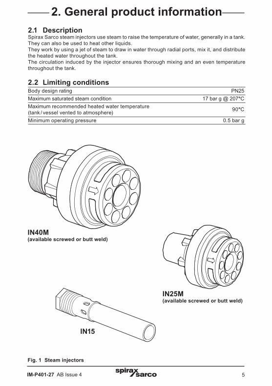
2.1 DescriptionSpirax Sarco steam injectors use steam to raise the temperature of water, generally in a tank. They can also be used to heat other liquids. They work by using a jet of steam to draw in water through radial ports, mix it, and distribute the heated water throughout the tank. The circulation induced by the injector ensures thorough mixing and an even temperature throughout the tank.
2.2 Limiting conditionsBody design rating PN25Maximum saturated steam condition 17 bar g @ 207°CMaximum recommended heated water temperature (tank / vessel vented to atmosphere) 90°C
Minimum operating pressure 0.5 bar g
2. General product information
IN25M (available screwed or butt weld)
IN40M (available screwed or butt weld)
IN15
Fig. 1 Steam injectors
IM-P401-27 AB Issue 46
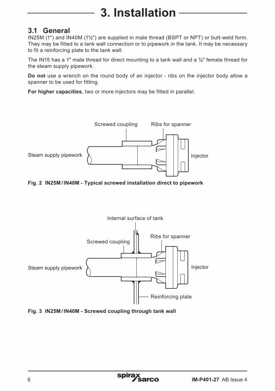
3. Installation3.1 GeneralIN25M (1") and IN40M (1½") are supplied in male thread (BSPT or NPT) or butt-weld form. They may be fitted to a tank wall connection or to pipework in the tank. It may be necessary to fit a reinforcing plate to the tank wall.
The IN15 has a 1" male thread for direct mounting to a tank wall and a ½" female thread for the steam supply pipework.
Do not use a wrench on the round body of an injector - ribs on the injector body allow a spanner to be used for fitting.
For higher capacities, two or more injectors may be fitted in parallel.
Fig. 2 IN25M / IN40M - Typical screwed installation direct to pipework
Screwed coupling Ribs for spanner
Internal surface of tank
Ribs for spanner
Reinforcing plate
Fig. 3 IN25M / IN40M - Screwed coupling through tank wall
Screwed coupling
InjectorSteam supply pipework
Steam supply pipework Injector
IM-P401-27 AB Issue 4 7
3.2 Pipeline sizingUse the same size pipe as the injector:-15 mm pipe for IN15, 25 mm pipe for IN25M and 40 mm pipe for IN40M.Pipe sizes for multiple injector installations are as follows:-
No. of injectors Type Minimum pipe size2 IN15 20 mm2 IN40M 65 mm3 IN40M 80 mm
Fig. 4 IN25M / IN40M - Typical butt welded installation through tank wall (on a standpipe)
Fig. 5 IN15 injector - Typical installation through tank wall
1" female socket Internal surface of tank
Reinforcing plate
Ensure holes are clear of the end of the socket
Ribs for spanner
Reinforcing plate
Internal surface of tank
Steam supply pipework Injector
Weld
Steam supply pipework Injector
IM-P401-27 AB Issue 48
3.3 Recommended layoutPosition the injector:- horizontally, - at low level, - on the vertical centre line of the tank, (single injectors), a minimum of 150 mm from the side of the tank.- At one end of the tank.The injector may be installed on a coupling through the tank wall, or on a short pipeline as close to the end of the tank as possible. Pipework may be run inside or outside the tank. We recommend the use of a suitable thread locking compound on all threaded connections. Discharge from the injector must be kept clear of any obstructions in the tank, e.g. pipework, stays, etc.The distance between the injector and the end of the tank (L) must be as great as possible for quietest operation. The following minimum dimensions apply:-
Steam pressure at injector inlet IN15 IN25M / IN40M (bar g) minimum length (L) minimum length (L) 0.5 - 7.0 250 mm 500 mm 7.1 - 10.0 300 mm 750 mm 10.1 - 14.0 350 mm 1 000 mm 14.1 - 17.0 400 mm 1 250 mm
A minimum depth of water must be allowed below the injector (H):- Injector type Minimum dimension IN15 100 mm IN25M 150 mm IN40M 200 mm
Dimension L
Dimension H
Minimum150 mmFig. 6
IM-P401-27 AB Issue 4 9
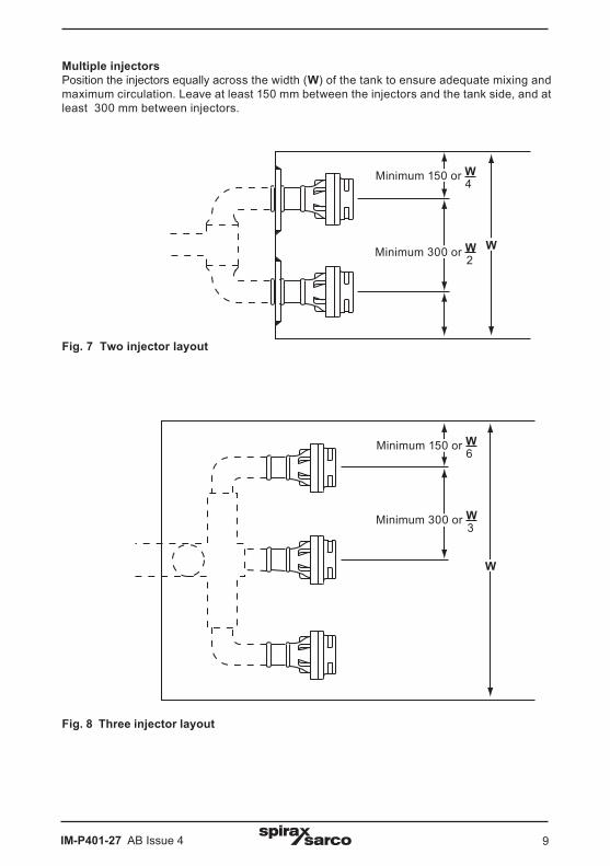
Multiple injectorsPosition the injectors equally across the width (W) of the tank to ensure adequate mixing and maximum circulation. Leave at least 150 mm between the injectors and the tank side, and at least 300 mm between injectors.
Fig. 8 Three injector layout
Fig. 7 Two injector layout
Minimum 150 or W 4
Minimum 300 or W 2
Minimum 150 or W 6
Minimum 300 or W 3
W
W
IM-P401-27 AB Issue 410
3.4 SystemsA typical system is shown in Figure 9. All system parts should be fitted in a horizontal pipeline situated above the top of the tank. We recommend the fitting of a stop valve and a Y-type strainer upstream of the control valve. Install the strainer on its side to prevent a water pocket forming. Install the sensor and sensor pocket approximately one third of the way up the tank, ideally above, or above and to one side of, the injector(s). For boiler feedtank applications, keep the sensor well away from the cold make-up, condensate return, and flash steam inlets. If used, install the dial thermometer near the sensor.
Controller and sensor
Stop valve
Control valve
Vacuum breaker
Pocket
Y-type strainer
Dial thermometer
Injector
Fig. 9
IM-P401-27 AB Issue 4 11
No specific maintenance is required. Any temperature controller should be calibrated periodically. We recommend an annual inspection of the injector and the steam supply pipework. Check that the injector discharge holes are not obstructed and that any screw threads are tight. Check that the tank vent is clear. Clean any strainer in the injector system.
If correctly sized, controlled, and installed in a suitable tank, the steam injector(s) will operate quietly with minimum noise and vibration. Noisy operation on installation could be caused by inadequately braced pipework or loose connections.
Excessive noise and / or vibration in service is extremely unusual, but could be caused by an injector becoming loose or detached, or by one or more of the injector outlet nozzles becoming blocked.
Heavy vibration may occur if the tank temperature is allowed to exceed 90°C, as the steam will not condense fully.
If severe vibration is experienced, do not continue to use the injector(s), or the tank may be damaged. Shut off the steam supply and investigate the fault immediately.