Model 64080 Model 64110 Bypass Pressure Control Or Shutoff Valves (Non-digital) Model 64002 Model 64082 Model 64124 Inline Pressure Control Or Shutoff Valves (Non-digital) And Applicable additional manuals: Aerospace Group Conveyance Systems Divison Carter ® Brand Ground Fueling Equipment IN64124 August 15, 1997 Installation Instructions
Transcript
Model 64080 Model 64110
Bypass Pressure Control Or Shutoff Valves (Non-digital)
Model 64002 Model 64082
Model 64124
Inline Pressure Control Or Shutoff Valves (Non-digital) And
Applicable additional manuals:
Aerospace Group Conveyance Systems Divison Carter® Brand Ground Fueling Equipment
IN64124August 15, 1997
Installation Instructions
August 15, 1997 IN64124
- 2 -
SUMMARY OF REVISIONS
DATE OFCHANGE
PARAGRAPH/PAGE
REVLTR
E.O.NO.
REVISION APPROVED
BY
8/15/97 Page 1 A Revised to release under EO
August 15, 1997 IN64124
- 3 -
TABLE OF CONTENTS
Para. Description Page
1.0 Scope ------------------------------------------------------ 42.0 Equipment Supplied by Customer--------------------- 43.0 General Description ------------------------------------- 44.0 Installation ------------------------------------------------ 54.1 Mounting on the Vehicle ------------------------------- 54.2 Air Bleeding --------------------------------------------- 114.3 Electrical Connections --------------------------------- 124.4 Pressure, Opening and Closing Control Setup------ 124.5 Installation/Adjustment of 64067 Maximum
Rate of Flow Pilot -------------------------------------- 14
1.0 SCOPE
These installation instructions havebeen developed for use in mountingCarter brand Model 64124/64080/64110 Inline Valves or 64060/64120 BypassValves on any refueling vehicle.There are several optional versionsof the 64110 In-line Valve and allversions are covered in these in-structions except for the digital ver-sion which is covered in separatemanual, IN64050. These instructionsdo not cover all requirements forsuch an installation which might bedictated by other authorities whichhave jurisdiction over the use of yourvehicle. The responsibility forproper final installation configurationis yours. Consult with the local air-port authority or corporate authorityfor further information.
2.0 EQUIPMENT SUPPLIED BYCUSTOMER
The following is a listing of the re-quired equipment supplied by thecustomer on the refueling vehicle.
All tubing needed to connect thevalve to the other components withinthe system.
On the basic 64110 (no options) thevalve is furnished less the solenoidvalve and opening and closing ori-fices. Customer must furnish needlevalves to achieve an adjustableopening and closing time.
All mounting hardware required.
3.0 GENERAL DESCRIPTION
The face-to-face distance of theANSI flanged versions of the 4 inchis 9.25 inches while the 3 inch meas-ures 8.0 inches.
The various valves covered by theseinstructions are described below.
64124 and 64080 - Air Set PressureControl Valves - These valves are di-rect acting units requiring an air ref-erence pressure set at approximately25 psi greater than the desired con-trol pressure. Typically they are con-nected to a Venturi to provide com-pensated pressure control at the noz-zle(s).
64002 and 64082 - Air Set By-passPressure Control Valve - These unitsare installed as a by-pass control toprovide compensated pressure to thenozzle(s). They are essentially thesame as the 64124 and 64080 exceptfor a lighter spring and the air refer-ence pressure is used to normallyclose the valve. As the nozzle pres-sure increases, these units open toallow more flow to by-pass the pumpreducing the control pressure. Thebias (difference between the air ref-erence pressure and the desired con-trol pressure) for these units is zeropsi, that is the air pressure is set atthe desired control pressure. The “B”option for both valves provides anadditional control that will allow theunit to open when the pump outletpressure exceeds the setting of thecontrol.
64110 - This unit is offered in fourvarieties as noted below.
� 64110 (no option) - A basicon-off valve for use as adeadman only type valve.This unit requires the addi-tion of a three-way, two po-sition solenoid valve and twoneedle valves by the customerto effect a proper deadmanshutoff valve with adjustable
August 15, 1997 IN64124
- 5 -
opening and closing timecontrols.
NOTE:
It might be less expensive toutilize two two-way solenoidvalves in lieu of a single 3-way. In that case followingthe wiring diagram for the
64110A3.
� 64110A1 or 64110B1 -Digital Pressure ControlValve - This unit is coveredin IN64050 and will not bediscussed further in thisdocument.
� 64110A2 or 64110B2 - FuelOperated Pressure ControlValve - This unit performsthe pressure control functionin a system where air is notavailable and incorporateseither 12 or 24 VDC solenoidcontrols for the deadmanfunction. The pressure con-trol function has a simpleadjustment.
� 64110A3 or 64110B3 - FuelShutoff Valve - The same asthe basic unit except either 12or 24 VDC solenoid controlsand integral orifices are fur-nished to result in a deadmanvalve with proper controlledopening and closing.
All of the various units above areavailable with ANSI flanges orVictaulic inlet and outlet as de-sired. See Bulletin 64124 for ad-ditional ordering information.
4.0 INSTALLATION
4.1 Mounting on the Vehicle
4.1.1 All of the subject units MUST bemounted HORIZONTALLY on thevehicle and all, except for the 64110(basic unit) and 64110A(B)2 ShutoffValves, mounted with the SolenoidValve assembly or the ports labeled“D” and “C” (in the case of older64124 Valves these ports may be la-beled “AIR” and “VENT”) on bot-tom of the unit (at the 6:00 o’clockposition). The two shutoff valvetypes (64110 and 64110A(B)2)should be installed with the solenoidvalves or ports “C” and “D” orien-tated on the top of the valve (at the12:00 o’clock position). Failure tocomply with this requirement will re-sult in poor performance of the units.
4.1.2 If clearance around the 64110, withthe solenoid or regulator package, isa severe problem, the solenoid valveassembly can be removed from thevalve and mounted near the valvewith new connections fabricated toappropriately connect the solenoidvalve assembly to the 64110 hous-ing. If the fittings are removed fromthe units and re-installed, DO NOTUSE TEFLON TAPE. Use Loctite59231 Pipe Sealant with Teflon forsealing pipe threads. CONSULTWITH CARTER FOR DETAILEDINFORMATION REGARDINGTHIS BEFORE TAKING ACTION.
4.1.3 The 64124/64080/64110A(B)2 willnormally be utilized with a Venturito effect proper compensated pres-sure control at the nozzle. Otherwisea remote pressure sensing port is re-quired to achieve a modicum ofproper pressure control. The ports orconnections to the various valves areto be connected to other locations on
August 15, 1997 IN64124
- 6 -
the refueling vehicle as noted in the table and figures below.
PART NUMBER PORT CONNECT TO COMMENTS
64124/64080 D 3/8 -18 NPT
Air Reference Pres-sure Regulator
Port may be labeled “AIR” onolder valves. See Figure 1 be-low.
64124/64080Continued.
C 1/4 -18 NPT
Slop Tank, main tankon refuelers or inletside of the pump(outlet of the by-passvalve if present).
If the port is left open leakagewill eventually become apparentfrom this vent signifying thatthe seals within the valve needrepairing.
B 1/4 -18 NPT
No connection neces-sary, this is an airbleed port. Port mustbe plugged.
A 3/8 -18 NPT
Fuel sense point, ei-ther a Venturi or staticsense point.
The valve is delivered with acheck valve/orifice installed inthe port in the body but there isan extended port for installationof the fuel sense connection.
64002/64082 D 3/8 -18 NPT
A 3-way air operatedvalve is installed inthis port offering threeother ports to whichthe following installa-tions are to be madeby the OEM:
A - Connect to themain line from theoutlet of the pump.
B - Connect to air ref-erence pressure regu-lator and to the fittingin port B on body.
C - Connect to Venturior sense port.
See Figure 2 below.
August 15, 1997 IN64124
- 7 -
FIGURE 1 - 64124/64080 IN-LINE CONTROL VALVE
PART NUMBER PORT CONNECT TO COMMENTS
C 1/4 -18 NPT
Slop Tank, main tankon refuelers or inletside of the pump(outlet of the by-passvalve if present).
If the port is left open leakagewill eventually become apparentfrom this vent signifying thatthe seals within the valve needrepairing.
B 1/4 -18 NPT
Connect this extendedport on all units, to theregulated air referencepressure.
See Figure 2 below.
A 1/4 -18 NPT
This port is pluggedon basic units. Onoption B units, a con-troller is installed inthis port. The port inthe controller (1/4 - 18NPT) is to be con-nected to the main linefrom the outlet of thepump.
See Figure 2 below.
August 15, 1997 IN64124
- 8 -
FIGURE 2 - BY-PASS CONTROL VALVE
PARTNUMBER
PORT CONNECT TO COMMENTS
64110 (basic) D 3/8 - NPT Connect to commonport of 2-position, 3-way solenoid valve.
See Figure 3 below. Connectnormally closed port of 3-waysolenoid valve through an adjust-able needle valve to port providedin inlet of valve body. Connectnormally open port of solenoidvalve through an adjustable nee-dle valve to slop tank, fuel storagetank or upstream of fuel pump.The needle valves will be used toprovide adjustable opening andclosing times for the unit.
August 15, 1997 IN64124
- 9 -
PARTNUMBER
PORT CONNECT TO COMMENTS
64110 (basic)Continued.
C & A 1/4 -18 NPT
B 1/4 - 18NPT
Furnished plugged.
Air breather fur-nished.
FIGURE 3 - 64110 (BASIC, NO OPTIONS) SHUTOFF VALVE(Customer furnishes solenoid, opening and closing orifice controls)
PART NUMBER PORT CONNECT TO COMMENTS
64110A2 or B2 D Used in Carter instal-lation connecting tosolenoid valves andrelief valve.
See Figure 4 below. The portleft open in the relief valve is tobe connected to the inlet side ofthe pump. The open port in thesolenoid manifold is to be con-nected to the slop tank, storagetank or inlet side of the pump.
August 15, 1997 IN64124
- 10 -
PART NUMBER PORT CONNECT TO COMMENTS
B & C
A 3/8 -18 NPT
Plugged by Carter
Connect port in checkvalve to Venturi orfuel sense port.
FIGURE 4 - 64110A(B)2 FUEL SET PRESSURE CONTROL VALVE
PART NUMBER PORT CONNECT TO COMMENTS
64110A3 or B3 D
A & C
B
Used in Carter instal-lation connecting tosolenoid valves.
Plugged by Carter
Breather installed byCarter
See Figure 5 below. The openport in the solenoid manifold isto be connected to the slop tank,storage tank or inlet side of thepump.
August 15, 1997 IN64124
- 11 -
FIGURE 5 - 64110A(B)3 FUEL SHUTOFF VALVE(Furnished with integral solenoid controls)
4.2 Air Bleeding
4.2.1 64124/64080 In-line Valves - Oncethe physical installation is completeand the vehicle is filled with fuel,upon first pressurization by thepump, the plug in port B must beloosened to bleed air from the fuelsense line and from the internal cav-ity of the 64124/64082. Cycling thedeadman on and off will cause thevalve to open and close and facilitatebleeding.
4.2.2 64002/64082 By-pass Valves - Thefittings connected to the C port onthe 3-way valve (one connected tothe sense line) must be loosened toeffect bleeding air from the line. Cy-cling the deadman will facilitate theoperation. On valves with the B op-
tion the fitting connecting the con-troller and the main line from thepump should also be loosened tobleed air from the line.
4.2.3 64110A(B)3 Shutoff Valves - If pos-sible, loosen the unused fitting (plug)on the end of the Solenoid ValveManifold Block as a bleeding point.Alternatively, loosen the fitting onthe side of the Manifold Block nextto the shorter of the two SolenoidValves to which the stainless steeltubing is attached. With pressureapplied to the inlet of the valve, acti-vate the Deadman Control to applypressure to this line. Air will escapefrom the loosened fitting. Fuel willsoon appear.
4.2.4 64110 (basic) Shutoff Valve -Loosen the fitting installed in port D.
August 15, 1997 IN64124
- 12 -
With pressure applied to the inlet ofthe valve, activate the DeadmanControl to apply pressure to the line.When most of the air is bled, slowlytighten the fitting to build pressurewithin the control cavity of the valve.This will cause the valve to open.After the valve has opened, re-loosenthe fitting. If loose enough, the valvewill stroke closed and exhaust sometrapped air from the internal controlcavity. Repeat this step until you aresatisfied that all the air is removedfrom the control line and from thecontrol cavity of the valve.
4.2.5 64110A(B)2 Fuel Set Pressure Con-trol Valve - Bleed the same as for64110A(B)3 above. In addition bleedthe same as for 64124 above.
4.3 Electrical Connections
4.3.1 64110 Valves furnished with electri-cal deadman control - The SolenoidValve assembly has two (2) electricconnectors attached to the two Sole-noid Valves (one per SolenoidValve). These connectors have ½”female NPT ports for connecting aconduit fitting, or other style fitting,for carrying incoming wires.
4.3.2 Remove these connectors by remov-ing the single screw at the center ofeach connector. With the screw re-moved (whether or not the connectorhas been pulled from the valve body)the cover will come off of the con-nector revealing the wiring connec-tion points within the connector.
4.3.3 There are three connection pointswithin the connector. The centerone, marked “GND”, will not beused in this installation. Two wireswill be used to connect each solenoidvalve to one side of the battery while
the other two are connected to thedeadman switch as shown in Figure4 & 5. (That are four (4) wires totalfor each 64124/64082.) THE TWOWIRES CAN BE CONNECTED TOTHE TWO POINTS WITHIN THECONNECTOR IN ANY ORDER.The solenoid valve will work thesame in either case.
4.3.4 To connect the two wires, strip about3/16 inch of insulation from the endof the wires, loosen the center screwof each connection point such thatthe stripped wire will enter the sideof the connections point, insert thewire, and tighten down the centerscrew to clamp the bare wire inplace.
4.4 Pressure, Opening and Closing Con-trol Setup
4.4.1 64124/64080 Air Set In-line Valves -The only operation needed to achievethe correct pressure control is, oncethe system is connected to a flow testrig, is to adjust the air reference pres-sure to 25 psi above the desired con-trol pressure, establish the desiredoptimum flow rate for the system,adjust the valve downstream of thenozzle connection until the valve be-gins to control. The resultant controlpressure should be that desired. Theclosing time is adjustable by an ori-fice screw located in port D, the airreference port. It is necessary, afterchecking the closing time to discon-nect the air line and remove the fit-ting to get to the adjustment. Coun-ter-clockwise turning of the orificescrew with decrease the closing timeand overshoot. It should be adjust-able over a range of from 2 - 5 sec-onds. Refer to Service Manual
August 15, 1997 IN64124
- 13 -
SM64124 or SM64080 for more in-formation on testing the units.
4.4.2 64110A(B)2 Fuel Set In-line Valves- The system is to be attached to aflow test rig. Activate the deadmanswitch to open the valve and estab-lish flow for at least 2 minutes tobleed the system. The fuel controlpressure is adjustable by opening orclosing the knob on the small reliefvalve mounted on the solenoid valvemanifold (bottom of the unit).Counter-clockwise movement of therelief valve knob will reduce thepressure control level. Be sure thatthe valve downstream of the nozzleon the test rig is shut down suffi-ciently to cause the valve to control.It is suggested that a low flow rate(150 gpm or so) be set up at first toassure the need to control. If thesystem is wide open the valve willnever sense the need to control andwill remain wide open. Fixed orificesare supplied to provide the industrystandard opening and closing timesof from 5 - 10 seconds for the formerand 2 - 5 for the latter
4.4.3 64110A(B)3 Shutoff Valves - Fixedorifices are supplied to provide theindustry standard opening and clos-ing times of from 5 - 10 seconds forthe former and 2 - 5 for the latter.
4.4.4 64110 basic Shutoff Valve - OEM isto furnish orifices in the form of ad-justable needle valves as mentionedearlier. The needle valve connecteddirectly to the slop tank primarilycontrols the closing time and the onein the inlet of the valve that is con-nected to the solenoid valve primar-ily controls the opening time. Adjusteach to achieve the desired times.Adjustment of one will have a slight
affect upon the other time. Trial anderror is the only way to achieve thisadjustment.
4.4.5 64002/64082 By-pass ControlValves - Aircraft Control Pressure -Apply air reference pressure equal tothe amount of desired control pres-sure. It is suggested that a low flowrate into the test rig (150-300 gpm orso, depending upon valve size) be setup at first to assure the need to con-trol. If the system is wide open thevalve will never sense the need tocontrol and will remain closed.
On option B units, the pump outletpressure at which the unit will opencan be varied using the followingmethod:
a). Loosen the locking nut on theController Assemblymounted in Port A.
b). Turn the hexagon bodyclockwise to its stop.
c). Turn the hexagon bodycounter-clockwise one fullrotation.
d.) With the pump on, open thedeadman to establish flowthrough into the test rig, thenkeeping the deadman acti-vated, close the flow with avalve downstream of the in-line valve. The by-pass valvewill go fully open.
e). Turn the body counter-clockwise to achieve the de-sired relief pressure at theoutlet of the pump.
f). Tighten the lock nut.
4.5 Installation/Adjustment of 64067Maximum Rate of Flow Pilot
August 15, 1997 IN64124
- 14 -
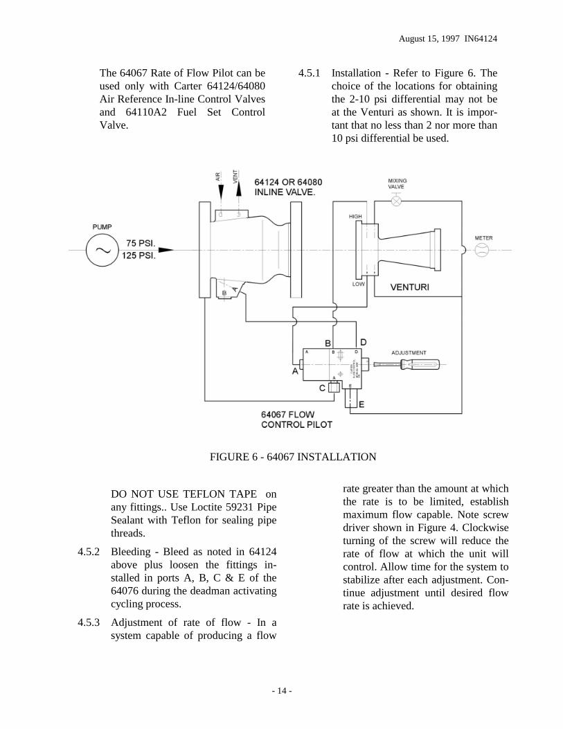
The 64067 Rate of Flow Pilot can beused only with Carter 64124/64080Air Reference In-line Control Valvesand 64110A2 Fuel Set ControlValve.
4.5.1 Installation - Refer to Figure 6. Thechoice of the locations for obtainingthe 2-10 psi differential may not beat the Venturi as shown. It is impor-tant that no less than 2 nor more than10 psi differential be used.
FIGURE 6 - 64067 INSTALLATION
DO NOT USE TEFLON TAPE onany fittings.. Use Loctite 59231 PipeSealant with Teflon for sealing pipethreads.
4.5.2 Bleeding - Bleed as noted in 64124above plus loosen the fittings in-stalled in ports A, B, C & E of the64076 during the deadman activatingcycling process.
4.5.3 Adjustment of rate of flow - In asystem capable of producing a flow
rate greater than the amount at whichthe rate is to be limited, establishmaximum flow capable. Note screwdriver shown in Figure 4. Clockwiseturning of the screw will reduce therate of flow at which the unit willcontrol. Allow time for the system tostabilize after each adjustment. Con-tinue adjustment until desired flowrate is achieved.
Aerospace GroupConveyance Systems Division 9650 Jeronimo RdIrvine, CA 92618 Ph (949) 452-9500 Fax (949) 452-9992