Page 1
Geotechnical Exploration Report
GSP Airport – New Cargo Ramp
Greer, Spartanburg County, SC
S&ME Project No. 1426-17-019
Prepared for:
W.K. Dickson & Company, Inc.
616 Colonnade Drive
Charlotte, North Carolina 28205
Prepared by:
S&ME, Inc.
48 Brookfield Oaks Drive
Greenville, South Carolina 29607
April 3, 2017
Page 2
S&ME, Inc. | 48 Brookfield Oaks Drive, Suite F | Greenville, SC 29607 | p 864.297.9944 | f 864.297.0462 | www.smeinc.com
April 3, 2017
W.K. Dickson & Company, Inc.
616 Colonnade Drive
Charlotte, North Carolina 28205
Attention: Mr. Greg Kershaw, P.E. (e-mail: [email protected] )
Reference: Geotechnical Exploration Report
Greenville-Spartanburg (GSP) Airport – New Cargo Ramp
Greer, Spartanburg County, South Carolina
S&ME Project No. 1426-17-019
Dear Mr. Kershaw:
S&ME, Inc. (S&ME) is pleased to submit this Geotechnical Exploration Report for the referenced project.
The exploration was made in general accordance with our Proposal No. 14-1700119 (dated February 15,
2017), and the Subconsultant Agreement For Professional Services (executed March 5, 2017) between
S&ME and W.K. Dickson & Company, Inc. (WKD). This report presents a description of our understanding
of the project, the exploration results, and our geotechnical conclusions and recommendations regarding
site grading and support for the new Cargo Ramp apron, building and associated pavements.
We appreciate the opportunity to work with W.K. Dickson & Company, Inc. by providing the geotechnical
engineering services for this project. Please contact us should any questions arise regarding the
information in this report or when further services are needed.
Sincerely,
S&ME, Inc.
Tripp Ford, P.E. Gant M. Taylor, P.E.
Project Engineer Senior Engineer
[email protected] [email protected]
Page 3
Geotechnical Exploration Report
GSP Airport – New Cargo Ramp
Greer, Spartanburg County, South Carolina
S&ME Project No. 1426-17-019
April 3, 2017 i
Table of Contents
1.0 Project Information ............................................................................................... 1
2.0 Exploration and Testing ....................................................................................... 2
3.0 Site Conditions ...................................................................................................... 5
Surface Features ................................................................................................................ 5
Area Geology..................................................................................................................... 6
Subsurface Conditions ..................................................................................................... 7
Surface Material .................................................................................................................. 7
Existing Fill ......................................................................................................................... 8
Cultivated Soils ................................................................................................................... 9
Residual Soils ...................................................................................................................... 9
Partially Weathered Rock / Auger Refusal ........................................................................ 10
Subsurface Water .............................................................................................................. 10
Laboratory Testing ............................................................................................................ 10
4.0 Site Grading Recommendations....................................................................... 11
Site Preparation ............................................................................................................... 12
Stripping ........................................................................................................................... 12
Drainage ............................................................................................................................ 12
Existing Fill ....................................................................................................................... 13
Silty/Clayey Soils .............................................................................................................. 13
Proofrolling and Subgrade Evaluation .............................................................................. 14
Excavation........................................................................................................................ 15
Fill Placement and Compaction .................................................................................... 16
Use of Excavated Soils as Fill ............................................................................................ 16
Use of Off-Site Borrow Materials as Fill ........................................................................... 17
Fill Slopes .......................................................................................................................... 17
Wet Weather Grading ....................................................................................................... 17
5.0 Structure Recommendations ............................................................................. 18
Spread Foundations ....................................................................................................... 18
Foundation Construction Recommendations .................................................................... 18
Page 4
Geotechnical Exploration Report
GSP Airport – New Cargo Ramp
Greer, Spartanburg County, South Carolina
S&ME Project No. 1426-17-019
April 3, 2017 ii
Settlement .......................................................................................................................... 19
Floor Slab ......................................................................................................................... 19
Seismic Conditions ......................................................................................................... 19
Retaining Walls ............................................................................................................... 20
6.0 Pavement Subgrade Recommendations ......................................................... 20
Subgrade Modulus Values ............................................................................................ 21
General Guidelines ......................................................................................................... 22
7.0 Limitations of Report .......................................................................................... 22
Appendix Appendix I - Figures
Boring Location Plans (7) – Figures 1 thr. 7
Generalized Subsurface Profiles (6) – Figures 8 thr. 13
Photographs of Field Conditions (3 pages)
Appendix II – Field Data
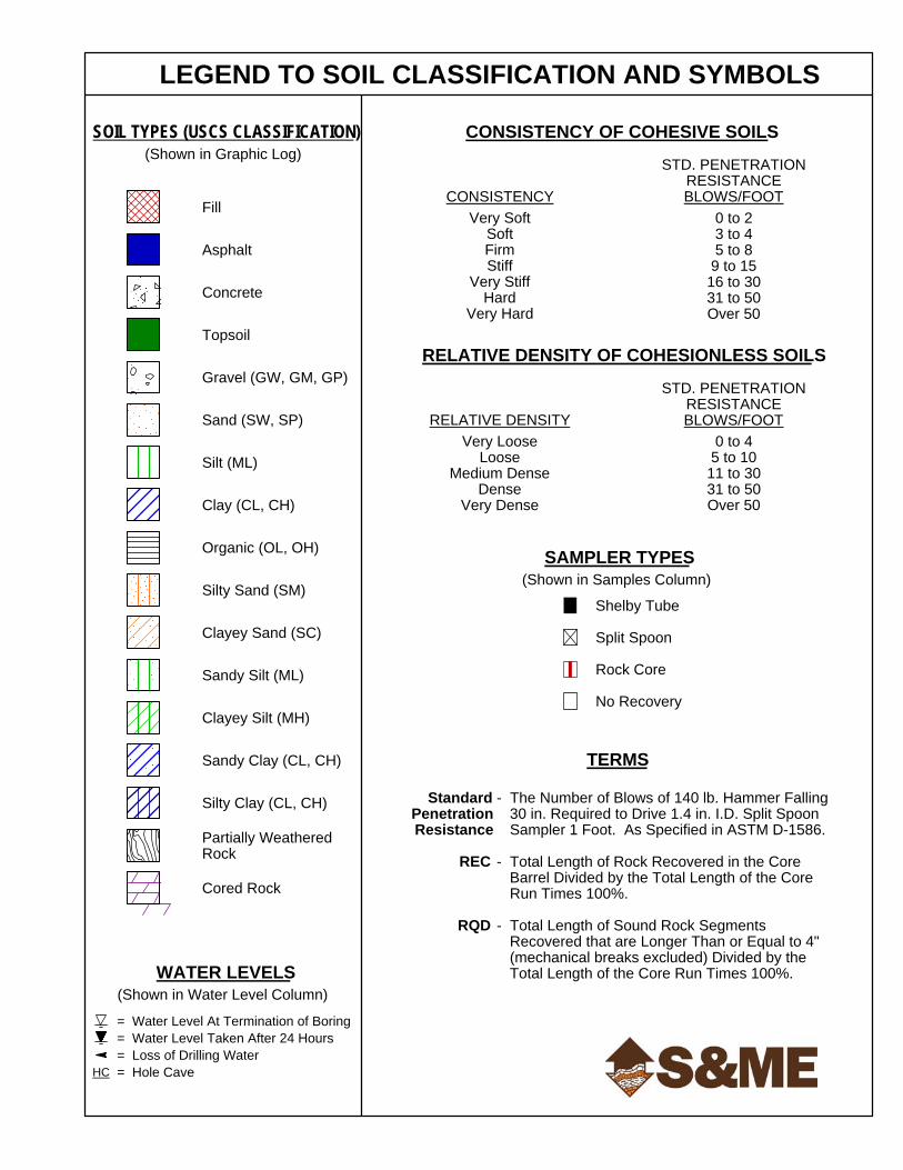
Legend to Soil Classification and Symbols
Soil Test Boring Logs (37)
Kessler DCP Test Data Tables (4)
Field Test Procedures
Appendix III – Laboratory Testing
Summary of Laboratory Test Data
Laboratory Test Reports (20)
Page 5
Geotechnical Exploration Report
GSP Airport – New Cargo Ramp
Greer, Spartanburg County, South Carolina
S&ME Project No. 1426-17-019
April 3, 2017 1
1.0 Project Information
We have prepared this report based on the following:
♦ Telephone conversations and e-mail transmittals between Mr. Greg Kershaw, P.E. of W.K. Dickson
(WKD) and Mr. Gant Taylor, P.E. of S&ME during the period of February 13 through 15, 2017;
♦ Review of the Preliminary Cargo Ramp Schematic - Boring/Coring Location Plan (Site Layout)
figure, provided by Mr. Kershaw as an attachment to the referenced February 13th e-mail, and
updated per our subsequent correspondence on February 15th;
♦ Site reconnaissance visits by Mr. Taylor during the period of March 2 through March 9, 2017;
♦ Review of FAA Advisory Circulars AC-150-5370-10G “Standards for Specifying Construction of
Airports” (dated July 21, 2014), and AC-150-5320-6F “Airport Pavement Design and Evaluation
(dated November 10, 2016);
♦ Review of historical aerial photographs of the site, available from the Google Earth website;
♦ Review of the 1958 and 1983 USGS Topographic Maps, which illustrate historic topographic
contours of the site area; and
♦ Review of historical aerial photographs of the site, available from the Spartanburg County GIS
website (which also illustrates the existing topographic contours and spot elevations).
From review of the referenced information and our conversations with Mr. Kershaw, we understand GSP
Airport plans to construct a new Cargo Ramp near the northeast end of the airport property, located
adjacent/southwest of the existing FedEx Distribution Center. Proposed development will include the
following:
• Construction of a 200-foot by 800-foot warehouse/distribution building, oriented perpendicularly
to the existing FedEx building;
• Installation of approximately 500,000 square feet of concrete pavement for the air-side apron;
• Approximately 160,000 square feet of pavement in front (southeast) of the warehouse building,
which includes approximately 137,000 square feet of heavy-duty apron for truck loading and
parking, and approximately 23,000 square feet of land-side light-duty parking lot;
• Approximately 1,350 linear feet of shoulder pavement rehabilitation/construction along Taxiway
“Lima”; and
• Approximately 1,500 linear feet of associated access driveways (which includes an approximately
1,100-ft long 2-lane divided entrance drive that will connect to Gateway Drive).
While detailed structural information was not provided to us at this time, we anticipate the warehouse/
distribution building will be a steel-framed structure with interior columns and perimeter masonry/precast
concrete walls. Column and wall loads will be supported by spread footings, with a concrete slab that will
match the elevation of the adjacent air-side concrete apron pavement. Based on our experience with
similar projects, we anticipate maximum column, wall, and slab loads will be on the order of 100 kips, 5
kips per linear foot (klf), and 250 pounds per square foot (psf), respectively. We are not aware of the
building settlement tolerances, or any settlement-sensitive sections of the building.
The land-side portion of the warehouse/distribution building will have loading dock retaining walls. As
shown on the provided site plan figure, a protective blast wall will be constructed near the northern
Page 6
Geotechnical Exploration Report
GSP Airport – New Cargo Ramp
Greer, Spartanburg County, South Carolina
S&ME Project No. 1426-17-019
April 3, 2017 2
corner of the apron ramp to shield the existing FedEx facility from the jets of reversing planes. We
anticipate the blast wall could be designed as a retaining wall. At this time we are not aware of any other
site retaining walls.
The proposed construction area covers land both inside and outside the existing perimeter security fence.
Inside the fence, the ground surface is relatively level to gently sloping, and covered by maintained grass
and pavements of the taxiway and service road. A sideline drainage swale, approximately 5 feet deep, is
present between the taxiway and service road. Outside of the fence, most of the planned development
area is grassed and generally level (very slightly pitched), except for fill embankment slopes and perimeter
ditching along the southeast side of this previously graded pad. From review of aerial photographs, it
appears this 26-acre portion of the GSP Airport was graded following construction of the FedEx facility in
approximately 2001. Additional observations of the site surface features will be described in further detail
later in Section 3.0 Site Conditions.
We estimate the ground surface topography varies only approximately 5 feet in total relief across the
graded pad. Although a preliminary grading plan is not yet available, we assume estimated maximum
cuts and fills will generally be minor, limited to about 3 feet or less to balance pad grading. A Finished
Floor Elevation (FFE) for the building has not been determined, but we anticipate it will be within about 1
to 2 feet of the current pad grade. Installation of site utilities will require deeper excavations. Also, fill
placement on the order of about 2 to 8 feet will be required to raise grades in the areas of the perimeter
ditches/swales (notably along the northeast end of the proposed building, where the building footprint
extends beyond the crest of the fill embankment slope).
The only topographically different area is an approximately 350-foot wide wooded section located
northeast of the graded pad (between the pad and Gateway Drive). This wooded area is approximately 10
feet higher in elevation than the surrounding areas, and we anticipate site grading will require excavation
of at least 5 feet to enable grade transitions along the entrance driveway between the Cargo Ramp facility
and the tie-in with Gateway Drive. Although this area was previously a portion of an apparent old grassed
runway (and possibly a material laydown yard during construction of the FedEx facility), it appears to have
been planted with rows of pine trees in 2007.
2.0 Exploration and Testing
The field exploration included a site reconnaissance by the Geotechnical Engineer and the performance of
thirty-seven (37) soil test borings. The boring locations were established in the field by our personnel,
using a handheld GPS unit (input with boring coordinates obtained from a geo-referenced site plan) and
by estimating distances from existing site features. The borings were staked near requested locations
shown on the provided figure titled Preliminary Cargo Ramp Schematic - Boring/Coring Location Plan
(updated February 15, 2017). The general locations/areas of the borings are outlined below, and these
areas are referenced within the report. The boring locations are also illustrated on the Boring Location
Plans (Figures 1 through 7) in Appendix I:
♦ Six borings (labeled C-1 through C-6) were performed to explore conditions for the proposed air-
side ramp entrance. Borings C-1 through C-4 were located along the paved outer shoulder of
Taxiway Lima; Borings C-5 and C-6 were located on the service road that parallels the taxiway;
♦ Two borings (labeled C-7 and C-8) were performed along Gateway Drive near the proposed
entrance driveway intersection tie-in;
Page 7
Geotechnical Exploration Report
GSP Airport – New Cargo Ramp
Greer, Spartanburg County, South Carolina
S&ME Project No. 1426-17-019
April 3, 2017 3
♦ Ten borings (labeled B-1 through B-10) were performed within the area of the air-side apron;
♦ Nine borings (labeled B-11 through B-19) were performed within/near the footprint area of the
proposed warehouse/distribution building; and
♦ Seven borings (labeled B-20 through B-26) were performed within the areas of the land-side
apron, parking and associated driveway pavements, located southeast of the building. Located
within the stand of pine trees, Boring B-26 was shifted slightly north of its planned location to
avoid cutting down any trees.
♦ We performed three additional borings (beyond the proposed scope) to further explore
conditions near three planned boring locations:
• Boring B-3A was performed roughly midway between B-3 and B-8 (near the south end of the
proposed blast wall) after we observed conditions at B-3 and B-8 were significantly different;
• Boring B-13A was performed near the crest of the fill embankment slope, as a companion to
B-13 (which was located in the bottom drainage swale at the toe of this slope), to help
characterize subsurface conditions in this area of the pad where the existing slope will likely
be extended to accommodate the building footprint; and
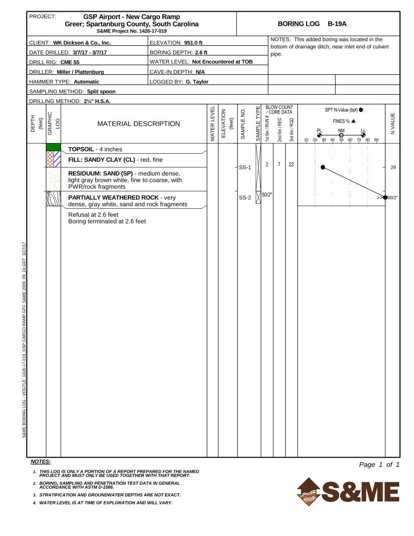
• Boring B-19A was performed in the bottom of the drainage swale near the inlet of the culvert
pipe (installed below the graded access path between the gravel service drive and the pad;
Boring B-19 was located in the backfill beside this pipe) to help evaluate the loose condition
of eroded sediments in the swale bottom.
As noted above, the graded pad is surrounded by perimeter swales to help drain surface water flow.
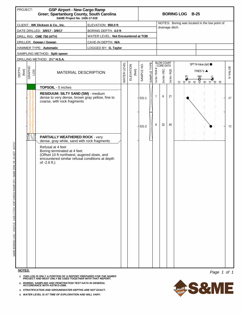
Several borings (B-3A, B-8, B-13, B-19A, and B-25) were located near the bottom of the deepest swale
along the eastern portion of the site; two borings (B-1 and B-2) were located near the bottom of the
shallow swale along the northwest side of the pad, and one boring (B-24) was located near the bottom of
the shallow swale along the southeast side of the pad.
S&ME completed the borings during the period of March 6 through 9, 2017. For pavement borings C-1
through C-8, we cored the pavement using a portable rotary coring machine with a 6-inch diameter
barrel. Each core penetrated the asphalt pavement and underlying stone base (if present), and we
measured the thickness of the pavement section layers. In most of the borings (all but C-7), we
performed Kessler Dynamic Cone Penetrometer (DCP) testing in general accordance with ASTM D 6951,
Standard Test Method for Use of the Dynamic Cone Penetrometer in Shallow Pavement Applications, to
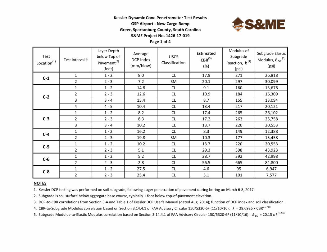
depths of approximately 3 to 5 feet below the pavement surface. Kessler DCP testing was also performed
adjacent to most of the borings located in the graded pad area. As presented in the summary table in
Appendix II, the Kessler DCP values were used to help estimate in-situ CBR values and relative stiffness
(and ultimately correlated to a subgrade modulus, k, for pavement design).
Borings were then performed through the coreholes with a truck-mounted CME 55 drill rig, using hollow-
stem auger techniques to advance the holes to their planned termination depths of 11 feet below the
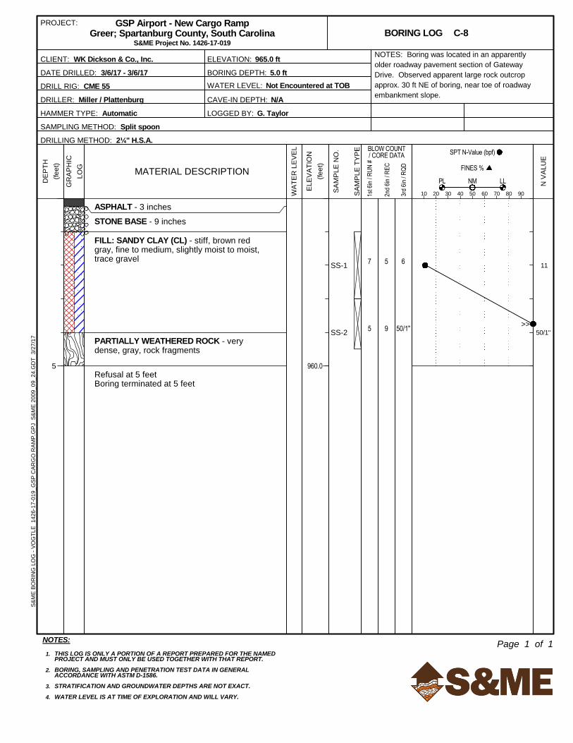
pavement surface. (Boring C-8 was terminated at 5 feet upon encountering auger refusal, apparently on
rock). Split-spoon samples and Standard Penetration Resistance (N) values were obtained at 2-foot
intervals in the borings. Upon completion of drilling and water level measurements at time of boring, the
boreholes were backfilled with soil cuttings (and a mechanical hole-plug) to the subgrade level. The
coreholes were then filled and patched with high-strength grout.
Page 8
Geotechnical Exploration Report
GSP Airport – New Cargo Ramp
Greer, Spartanburg County, South Carolina
S&ME Project No. 1426-17-019
April 3, 2017 4
Borings B-1 through B-26 were performed with both the CME 55 drill rig and an ATV-mounted CME 750
drill rig, both using hollow-stem auger techniques to advance the holes. (The ATV-mounted rig was
mobilized to the site after we observed the ground surface in the lower areas of the pad were wet and
unstable following rainfall.) Split-spoon samples and Standard Penetration Resistance (N) values were
obtained with an automatic hammer at 2-foot (generally continuous) intervals in the upper 10 feet, and
then at 5-foot intervals thereafter. At twenty-one (21) locations, the borings encountered auger refusal
shallower than the planned depth (20 feet for building borings, and 10 feet for pavement borings). At
most of these shallow refusal locations, we offset approximately 10 feet laterally and performed an
additional offset auger boring to further evaluate the refusal conditions (which generally encountered
similar refusal).
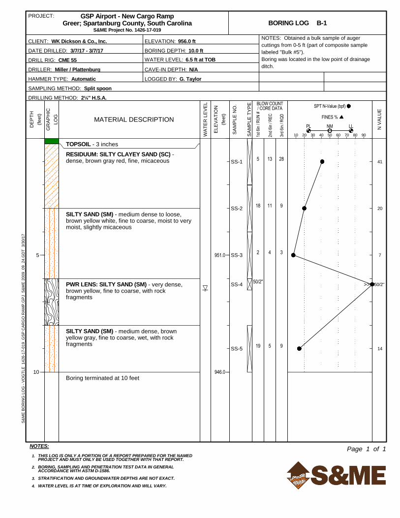
In addition to the SPT sampling, we also collected bulk samples of the auger cuttings (from the upper 3 to
5 feet of soil) from many of the borings. As described later, we evaluated and combined these samples
into seven composite bulk samples, blended by similar soil types (i.e., predominantly sandy, clayey, or silty)
and grouped into general areas, to provide a range of subgrade modulus values for the representative soils
encountered across the site.
After completion of drilling, we measured the depth to subsurface water at the time of boring (TOB).
Although the borings in existing pavement areas (C-1 through C-8) were backfilled immediately, most of
the other boreholes in the pad area were allowed to remain open to measure subsurface water levels the
next day. Where present in the boring, the depth to water was measured and recorded. If water was not
present, the hole cave-in depth was measured and recorded. We then backfilled the boreholes with soil
cuttings, and installed a mechanical hole plug near the surface in each boring to help reduce borehole
settlement.
The split-spoon samples and bulk samples were transported to our laboratory, where the Geotechnical
Engineer visually and manually classified the soils in general accordance with the guidelines of the Unified
Soil Classification System (USCS). The results of the classifications and the field testing results are
presented on the individual Boring Logs in Appendix II. The composite bulk samples were subjected to
laboratory index testing (moisture content, Atterberg limits, and sieve analysis) to aid in the classification
and evaluation of the soil’s engineering properties. We also performed Modified Proctor compaction and
California Bearing Ratio (CBR) testing on the bulk samples to help evaluate the soil’s pavement support
characteristics and suitability for use as structural fill. Appendix III contains the individual laboratory test
reports and Summary of Laboratory Test Data table.
In addition to the Appendix items referenced above, Appendix I also contains six Generalized Subsurface
Profiles (Figures 8 through 13), Photographs of Field Conditions (3 pages) and Time-Elapsed Aerial
Photographs (from the Spartanburg County GIS website); and Appendix II contains a Legend to Soil
Classification and Symbols, the Kessler DCP Test Data Tables (4 pages), and the Field Testing Procedures.
Ground surface elevations shown on the Boring Logs and Generalized Subsurface Profiles were interpolated
from the topographic contour data available on the Spartanburg County GIS website. Based on the
methods used, the boring locations and elevations should be considered approximate.
Page 9
Geotechnical Exploration Report
GSP Airport – New Cargo Ramp
Greer, Spartanburg County, South Carolina
S&ME Project No. 1426-17-019
April 3, 2017 5
3.0 Site Conditions
Surface Features
Some of the surface feature information was initially described above in Section 1.0 Project Information,
and is supplemented in this report section. From our review of historical aerial photographs from the
Google Earth and Spartanburg County websites, in addition to previous research of the GSP Airport
history, the following is an approximate timeline of previous development in the project site vicinity:
♦ Original airport construction was in 1962 (not visible on the 1958 USGS Map, Figure 7);
♦ The 1983 USGS Map (Figure 6) and 1994 aerial photograph (Figure 5) show the former grass
runway terminating near the northeast end of the runway/taxiway;
♦ By 1996, the runway and taxiway had been extended to the northeast, along with construction of
the parallel service road, an apron at the northeast end of the taxiway, and Gateway Drive (these
features were not visible on the 1994 aerial photograph, Figure 5);
♦ Construction of the adjacent FedEx Distribution facility was completed in 2001 (construction
materials testing was performed by S&ME);
♦ The 2004 aerial photograph indicates the grading of the 26-acre area behind (southwest of)
FedEx, herein referenced as the “graded pad”, and associated detention pond had been
completed. We are not aware of any construction records which document the site grading
(observations or density testing during fill placement and compaction);
♦ In 2013, it appears the portion of Gateway Drive from (and including the intersection near) FedEx
to S.C. Highway 101 was re-surfaced or rehabilitated; and
♦ In 2015, a gravel driveway was constructed between the FedEx truck apron and the toe/swale
along the northeastern side of the graded pad, extending from the southern corner of the FedEx
parking lot to the service road. Besides this (and the growth of pine trees in the remaining
portion of old grass runway southeast of FedEx), there did not appear to be any other significant
changes to the surface features of the graded pad or taxiway between 2004 and present day.
The 1994 aerial photograph (Figure 5) indicates possible exposed rock at the ground surface in the
southern portion of the site, as an isolated area not covered by trees. Although not included in the time-
lapsed photographs in the Appendix, review of historic aerial photographs in Google Earth indicate the
wooded area south and east of the detention pond was clear-cut in approximately 2009. This clearing
revealed several areas of exposed rock at the ground surface, in close proximity to the graded pad (similar
to the 1994 observation within the pad), suggesting shallow rock is prevalent across this vicinity.
Topographic contour data available from the historic USGS Maps and Spartanburg County GIS website
should typically be considered approximate, although review of the data indicates significant grading has
occurred within the project construction area during multiple periods (described above). Currently, the
ground surface elevation of the graded pad varies from approximately 955 feet to 960 feet (pitched gently
from the pad’s central ridge toward perimeter drainage swales). The USGS Maps indicate the original
ground surface elevations within the project area varied from approximately 984 feet to 950 feet,
generally sloping downward from north to south toward drainage features and a creek. Compared to
current grades, it appears the northern half of the pad was excavated (cut) down as much as 20+ feet, and
the southern half of the pad was filled at least 10 feet during previous site grading.
Page 10
Geotechnical Exploration Report
GSP Airport – New Cargo Ramp
Greer, Spartanburg County, South Carolina
S&ME Project No. 1426-17-019
April 3, 2017 6
As shown in the photographs in Appendix I, the pavements of the taxiway shoulder and parallel service
road are in moderate condition, considering their age (at least 20 years). These pavements exhibited
longitudinal cracking (along joints between adjacent “pulls”/”lanes”) and transverse cracks, which had
been sealed. We observed localized greater fatigue cracking on the service road near Boring C-6, which
also had been sealed. The recently resurfaced pavements of Gateway Drive appear in good condition;
however, the older pavement of Gateway Drive (the transition occurs approximately 150 feet southeast of
the intersection, roughly midway between borings C-7 and C-8) is in moderate condition. Review of
Google Earth aerial photographs indicates increased transverse cracking has occurred in the eastern leg of
Gateway Drive over the past 3 to 4 years.
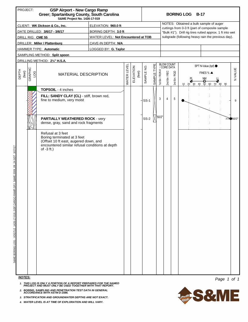
As noted, our first day of field exploration was March 6, 2017. Rainfall occurred on the night before our
arrival. Although the ground surface initially appeared to be generally stable, the tires of the truck-
mounted rig deeply rutted the ground surface as it approached boring B-17 near the middle of the
graded pad (see photograph). We then observed standing water in several areas in the southern half of
the pad (in the area south of the general delineation of borings B-11/B-14/B-17/B-22). Although most of
the graded pad is covered with grass, we observed other different types of grass vegetation growing in
the southern wetter areas. Refer to the 2005 aerial photograph (Figure 4) in Appendix I which depicts a
difference in ground color, similar to observations during our reconnaissance. These conditions, in
conjunction with very slight pitch of the ground surface, suggest insufficient drainage in this southern
area. Surface drainage for the southern half of the pad is directed south to shallow perimeter drainage
swales that direct flow to a drop inlet (that discharges to the nearby detention pond).
Surface drainage for the northern half of the graded pad is directed north to a shallow perimeter drainage
swale that directs flow to the larger swale along the northeast side of the pad. This primary swale parallels
the 2015 gravel driveway (roughly 2 feet lower than the driveway) and follows along the toe of the pad
embankment. Compared to the grade at the pad slope crest, the depth of the swale bottom increases from
northwest to southeast, from about 1 foot near the north corner of the pad (near boring B-3) to 10 feet
near the east corner (near Boring B-25). The associated slope face, from pad crest to swale toe, is inclined
gently to moderately downward at an inclination shallower than about 5H:1V (horizontal to vertical).
Because the field work occurred over several days during the week of March 6, we were able to observe
changes in subgrade conditions over time, and as affected by prevailing weather. Early in the week, the
weather was cool and rainy, and as noted above, the subgrade conditions were moist/wet and generally
unstable in the southern half of the pad. (Notably, the subgrade conditions in the northern half of the pad
were less affected by the rainy weather, and maintained some stability even following rainfall.) On
Wednesday and Thursday (March 8 and 9), however, the weather improved to warmer near 70 degrees,
with higher speed winds. These conditions promoted drying of the subgrade with improved stability, such
that by Wednesday afternoon, we could drive trucks across the southern half of the pad without rutting.
Also, on Thursday March 9, we observed soil cuttings brought to the ground surface by the drilling augers
dried very quickly when subjected to the warm temperature and high winds.
Area Geology
The project site is in the Piedmont Physiographic Province of South Carolina. The Piedmont
Physiographic Province is a relatively broad strip extending from central Alabama across Georgia and the
Carolinas into Virginia. Rocks of the Piedmont occur in belts that are some of the oldest formations in the
United States. The rock types are primarily metamorphic gneiss and schist with some granite intrusions.
Page 11
Geotechnical Exploration Report
GSP Airport – New Cargo Ramp
Greer, Spartanburg County, South Carolina
S&ME Project No. 1426-17-019
April 3, 2017 7
The major portion of the bedrock in the Piedmont is covered with a varying thickness of residual soil
which has been derived by chemical decomposition and physical weathering of the underlying rock.
Residual soils developed during the weathering of this bedrock consist predominately of micaceous sandy
silts and silty sands which grade to clayey silts and silty clays with nearness to the ground surface. The
thickness of the residual soils can vary from only a few feet to in excess of 100 feet.
The boundary between the residual soil and the underlying bedrock is not sharply defined. Generally, a
transition zone consisting of very hard soil to soft rock, appropriately classified as “partially weathered
rock,” (PWR) is found. Within the transition zone, large boulders or lenses of relatively “fresh” rock which
are generally much harder than the surrounding material often exist. The irregular bedrock surface is
basically a consequence of differential weathering of the various minerals and joint patterns of the rock
mass. It is also common for boulders rock pinnacles to be encountered within the PWR zone.
Portions of the natural geological profile of the site have been modified by past grading activities that
have resulted in the placement of fill and/or disturbance of the upper natural soil. From review of historic
aerial photographs and USGS Maps, it appears the site has been graded at multiple times in the past.
Please keep in mind that existing fill can vary in composition and consistency, and the engineering
characteristics of existing fill can be difficult to predict. Although there is no specific correlation between
the degree of compaction of existing fill and the results of penetration testing, a qualitative assessment of
existing fill can often be made based on visual observation of the fill materials sampled in the borings and
the general magnitude of the penetration test values.
The typical Piedmont soil profile can also be altered through activities such as agricultural farming and
cultivation, which create a disturbed soil layer. These “cultivated” or “disturbed” soils often exist in a loose
or soft condition and are highly sensitive to moisture content changes. Previously cultivated soils may also
contain a higher concentration of roots and organic material. The presence of cultivated soil suggests that
portions of the site were likely used for agricultural farmland prior to its current development.
Subsurface Conditions
The following description of subsurface conditions is relatively brief and general. For more detailed
information, the individual Borings Logs contained in the Appendix should be consulted. Similar soils
were grouped into strata on the logs. The strata contact lines represent approximate boundaries between
soil types; the actual transition between soil types in the field could be gradual in both the horizontal and
vertical directions.
Surface Material
Borings B-1 through B-26 initially penetrated a layer of organic topsoil at the ground surface. Across the
graded pad, the topsoil thickness generally varied from 2 inches to 5 inches. In the perimeter drainage
swales, the topsoil thickness varied from 3 inches to 8 inches (and was generally thicker in the southern
half of the site). The pavement cores at the following eight boring locations encountered asphalt
pavement of variable thickness and underlying material, as tabulated below.
Page 12
Geotechnical Exploration Report
GSP Airport – New Cargo Ramp
Greer, Spartanburg County, South Carolina
S&ME Project No. 1426-17-019
April 3, 2017 8
Table 3-1: Cored Pavement Section Thicknesses
Pavement
Core #
Asphalt
Thickness
Underlying
Material
Total
Section
Thickness
Location Notes
C-1 2-3/4” 10" stone base 12-3/4” Taxiway shoulder, middle “pull/lane”
C-2 2-5/8” 10-3/8" stone base 13” Taxiway shoulder, outer “pull/lane”
C-3 2-1/2” 8-1/2" stone base 11” Taxiway shoulder, outer “pull/lane”
C-4 2-3/4” 9-1/4" stone base 12” Taxiway shoulder, middle “pull/lane”
C-5 3-1/8”
(2 layers)8" stone base 11-1/8” Service Road, south/west-bound lane
C-6 3-1/4”
(2 layers)7-3/4" stone base 11” Service Road, north/east-bound lane
C-7 6” 8” cement-treated
base course 14” Gateway Drive, 2014 resurfaced portion
C-8 3” 9" stone base 12” Gateway Drive, non-resurfaced portion
The topsoil and pavement section thicknesses will vary beyond the boring locations, in unexplored areas
of the site.
Existing Fill
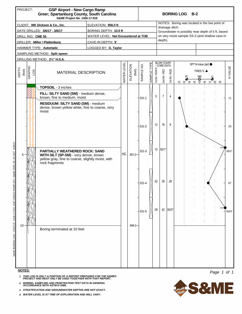
Existing fill soils were encountered beneath the surficial materials in most of the borings (30 of the 37
total borings), generally extending to depths of about 1 to 9 feet below the existing ground surface. The
sampled fill varied widely in composition, consisting mostly of sandy clay (USCS symbol CL), silty sand
(SM), clayey sand (SC), and sandy silt (ML). Trace (less than 5%) organic roots, gravel, and/or rock
fragments were noted in portions of the fill sampled. Most of the N-values recorded in the fill ranged
from 8 to 38 blows per foot (bpf), suggesting a variable (low to moderately high) degree of compaction
was applied. However, some of these N-values were likely amplified by gravel and rock fragments within
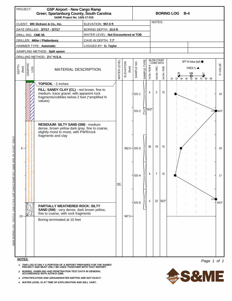
the fill. Boring B-4 encountered a layer of apparent rock cobbles near the bottom of the fill zone between
2 and 3 feet. The lower N-values were also measured near the ground surface, where the near-surface fills
have likely been softened by exposure to standing water (and freeze/thaw cycles) over the past 15 years.
One very low N-value of 3 bpf was measured in the fill in boring B-26; although this condition is likely
indicative of this area being previously used for a material lay-down yard.
Below the taxiway shoulder pavement section, the existing sandy clay fill in borings C-1 through C-4 was
approximately 6 to 12 inches thick and appeared to have been placed as a sub-base course. Although
most of this portion of the taxiway had been apparently “cut” to current grade, it is common for a layer of
compacted select fill to be placed as a sub-base course for pavements. Similarly, although much of the
northern half of the graded pad was apparently in an area of shallow to deep cut (comparing current
grades to historic/original grades), we observed many of the borings in the northern “cut” portion still
encountered a thin (1- to 2-foot thick) layer of fill near the ground surface.
Within pavement borings C-1 through C-8, a total of six Kessler DCP index values were measured within
the sandy clay (CL) fill layer below the existing pavement section. CBR values correlated from DCP index
values were widely scattered, ranging from 4.6 percent (in stiff CL at boring C-8) to 17.9 percent (in stiff CL
Page 13
Geotechnical Exploration Report
GSP Airport – New Cargo Ramp
Greer, Spartanburg County, South Carolina
S&ME Project No. 1426-17-019
April 3, 2017 9
at boring C-1). These low and high CBR values correlate to Modulus of Subgrade Reaction (k) values of
approximately 95 pci and 270 pci, respectively. At borings performed in the graded pad area, a total of
forty-two Kessler DCP index values were measured within the fill layer, and the DCP testing was
performed within a variety of soil types (CL, SM, SC, and ML). CBR values correlated from DCP index
values were widely scattered, ranging from 0.9 percent (in soft, very moist CL at boring B-17 – where
subgrade rutting occurred) to 33.6 percent (in medium dense SM at boring B-7). These low and high CBR
values correlate to Modulus of Subgrade Reaction (k) values of approximately 30 pci and 440 pci,
respectively.
Fill soils tend to become wet due to rainwater runoff infiltrating these type soils and becoming trapped or
“perched” above layers of more consistent residual soils (or shallow partially weathered rock). Additional
fill will likely be present in unexplored areas of the site, such as in deeper sections of the graded pad. The
depth and composition of fill in unexplored areas will vary and could be deeper, erratically compacted,
and/or contain excessive organic matter.
Cultivated Soils
Below the fill at depths varying from approximately 2½ to 9 feet, five borings (B-16, B-18, B-21, B-23, and
B-24) in the southern portion of the site, encountered a ½- to 1-foot thick layer of material resembling
previously cultivated soils. Notably, this material was encountered below the fill, and just above the
partially weathered rock or refusal level in these borings (described below). The sampled cultivated soil
typically consisted of sandy clay (CL) and clayey sand (SC). The cultivated soil contained trace to some
organic roots and gravel, and we observed it was moist to very moist. The N-values recorded in the
cultivated soil ranged from 5 to 18 bpf, although the higher N-values were likely amplified by gravel.
Review of the 1958 USGS Map indicates the southern half of the site could have been used for farming in
the past, as much of the rural land use in this area was previously agrarian.
Residual Soils
Residual soils (residuum) of the type common to the Greer area were encountered beneath the surface
materials or fill in most of the borings (exceptions to this condition were the several borings where
weathered rock was encountered immediately below the fill or cultivated soil). The residuum primarily
consisted of sandy clay (CL), clayey sand (SC), and silty sand (SM); with a lesser proportion consisting of
silty clay (CL), sandy silt (ML), sand with silt (SP-SM), and sand (SP). Some of the residual soil samples
contained rock fragments and variable amounts of mica. The N-values recorded in the residual soils
ranged from 4 to 77 bpf, indicating a soft to very hard consistency for the clays/silts, and a loose to very
dense relative density for the sands. The lower N-values were generally measured in residual soils near
the subsurface water level. Due to widespread shallow weathered rock/refusal conditions (described
below), only ten borings were terminated in residuum at their planned depths of 10 to 20 feet below the
existing ground/pavement surface. These borings (C-1, C-2, C-4 through C-7; and B-1, B-6, B-8, and B-11)
were generally located in the northern and western portions of the site.
Within pavement borings C-1 through C-8, a total of eleven Kessler DCP index values were measured
within the residuum below the fill or existing pavement section, and the DCP testing was performed
predominantly in sandy clay CL (and some SM). CBR values correlated from DCP index values were widely
scattered, with most ranging from 8.7 percent (in stiff CL at boring C-2) to 29.3 percent (in hard CL at
boring C-5). These low and high CBR values correlate to Modulus of Subgrade Reaction (k) values of
approximately 155 pci and 400 pci, respectively. At borings performed in the graded pad area, a total of
Page 14
Geotechnical Exploration Report
GSP Airport – New Cargo Ramp
Greer, Spartanburg County, South Carolina
S&ME Project No. 1426-17-019
April 3, 2017 10
twenty-one Kessler DCP index values were measured within the residuum, and the DCP testing was
performed within a variety of soil types (CL, SM, SP-SM, and ML). CBR values correlated from DCP index
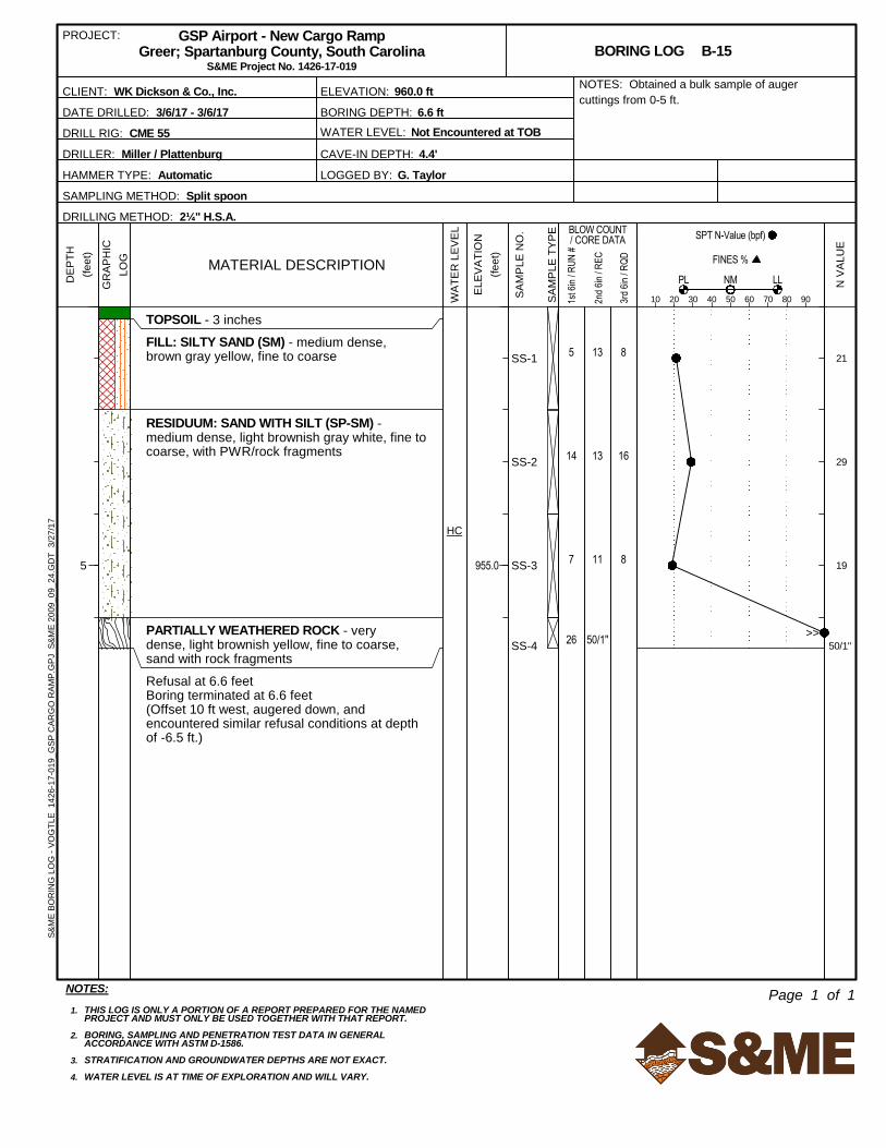
values were widely scattered, ranging from 5.7 percent (in stiff CL at boring B-3) to 81.8 percent (in very
dense SM at boring B-5). These low and high CBR values correlate to Modulus of Subgrade Reaction (k)
values of approximately 110 pci and 890 pci, respectively (although the higher values were likely amplified
by partially weathered rock, and not necessarily representative of the soil consistency).
Partially Weathered Rock / Auger Refusal
Most of the borings (28 of the 37 total borings) encountered partially weathered rock (PWR) and/or auger
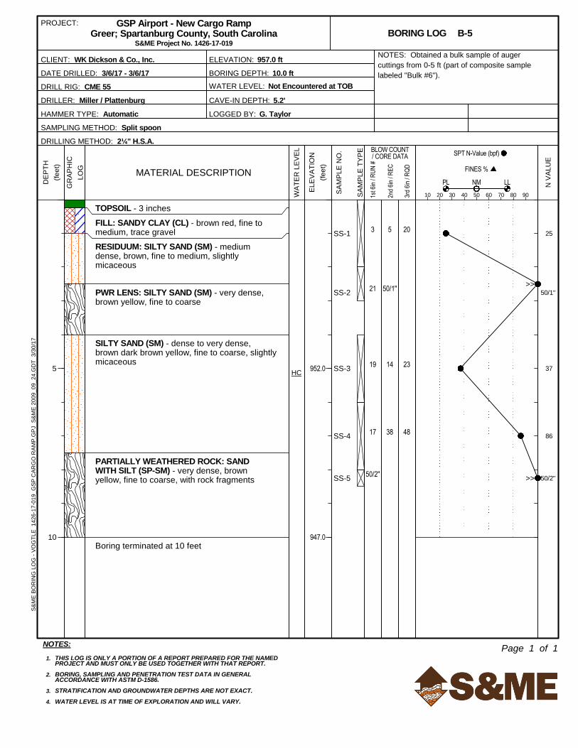
refusal at depths shallower than their planned termination depths. Borings B-1, B-5 and C-1 encountered
PWR lenses in the residual soil zone at depths ranging from 2½ to 6 below the ground surface. Borings
B-2 through B-6, and C-3, encountered continuous PWR at depths of 4½ to 9 feet, and penetrated PWR
to their planned termination depths of 10 and 11 feet. Borings B-7, B-9 through B-26, and C-8,
encountered PWR at depths of 1 to 8½ feet, penetrated a relatively thin layer of PWR (ranging in
thickness from a few inches to about 2½ feet) and then encountered auger refusal at depths ranging from
1.2 to 10 feet. At most of these shallow refusal locations, we offset approximately 10 feet laterally and
performed an additional offset auger boring to further evaluate the refusal conditions (which generally
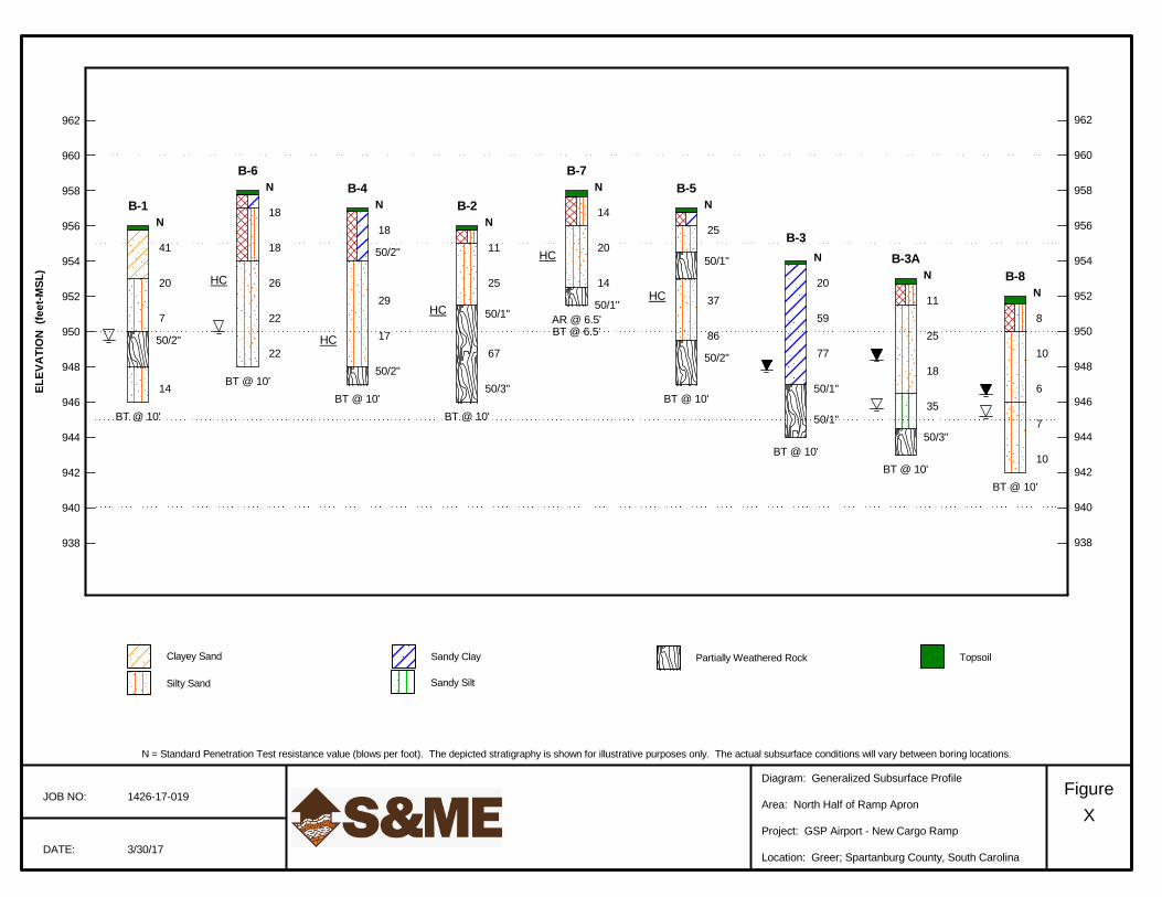
encountered similar refusal). As illustrated on the Generalized Subsurface Profiles (Figures 8 through 13) in
Appendix I, correlating these depths with site elevations indicates PWR as shallow as approximate El. 958
feet, and refusal as shallow as approximate El. 957 feet. For the southern entrance driveway, boring B-26
(located in the currently wooded area) encountered shallow refusal at a depth of approximately 4.5 feet,
near El. 963 feet.
The PWR was generally classified as very dense silty sand (SM), sand (SP), and sand with silt (SP-SM) with
rock fragments. N-values of greater than 50 blows per 6 inches were measured in the PWR zone. Based
on our observation of the drill rig operation at the refusal levels, auger refusal in the borings is apparently
indicative of mass rock.
Subsurface Water
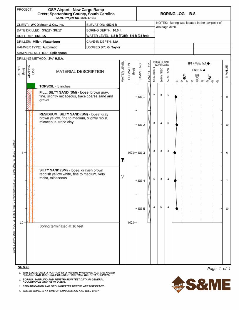
Subsurface water was encountered in five borings (B-1, B-3, B-3A, B-6, and B-8), either at termination of
boring (TOB) or after a period of 24 hours, at depths ranging from 4.6 to 8.0 feet below the ground
surface. As illustrated on the Generalized Subsurface Profiles (Figures 8 through 13) in Appendix I, these
depths correspond with site elevations ranging from approximately El. 950 feet to El. 947 feet. Several
borings indicated hole cave-in depths within this elevation range (in conjunction with observed very moist
soil samples), suggesting that subsurface water could be slightly below the cave-in depth. The presence
of shallow PWR and refusal/rock conditions likely affects the subsurface water level at this site (as
subsurface water can perch above these materials). It should also be noted that subsurface water levels
will fluctuate during the year, due to such things as seasonal variations, precipitation, and construction
activity in the area.
Laboratory Testing
As previously discussed in Section 2.0 Exploration and Testing, we collected bulk samples of the auger
cuttings (from the upper 3 to 5 feet of soil) from many of the borings. We evaluated and combined these
samples into seven composite bulk samples, blended by similar soil types (i.e., predominantly sandy, clayey,
or silty) and grouped into general areas, to provide a range of subgrade modulus values for the
Page 15
Geotechnical Exploration Report
GSP Airport – New Cargo Ramp
Greer, Spartanburg County, South Carolina
S&ME Project No. 1426-17-019
April 3, 2017 11
representative fill and residual soils encountered across the site. In addition to laboratory index testing
(moisture content, Atterberg limits, and sieve analysis) we performed Modified Proctor compaction and
California Bearing Ratio (CBR) testing on the composite bulk samples to help evaluate the soil’s pavement
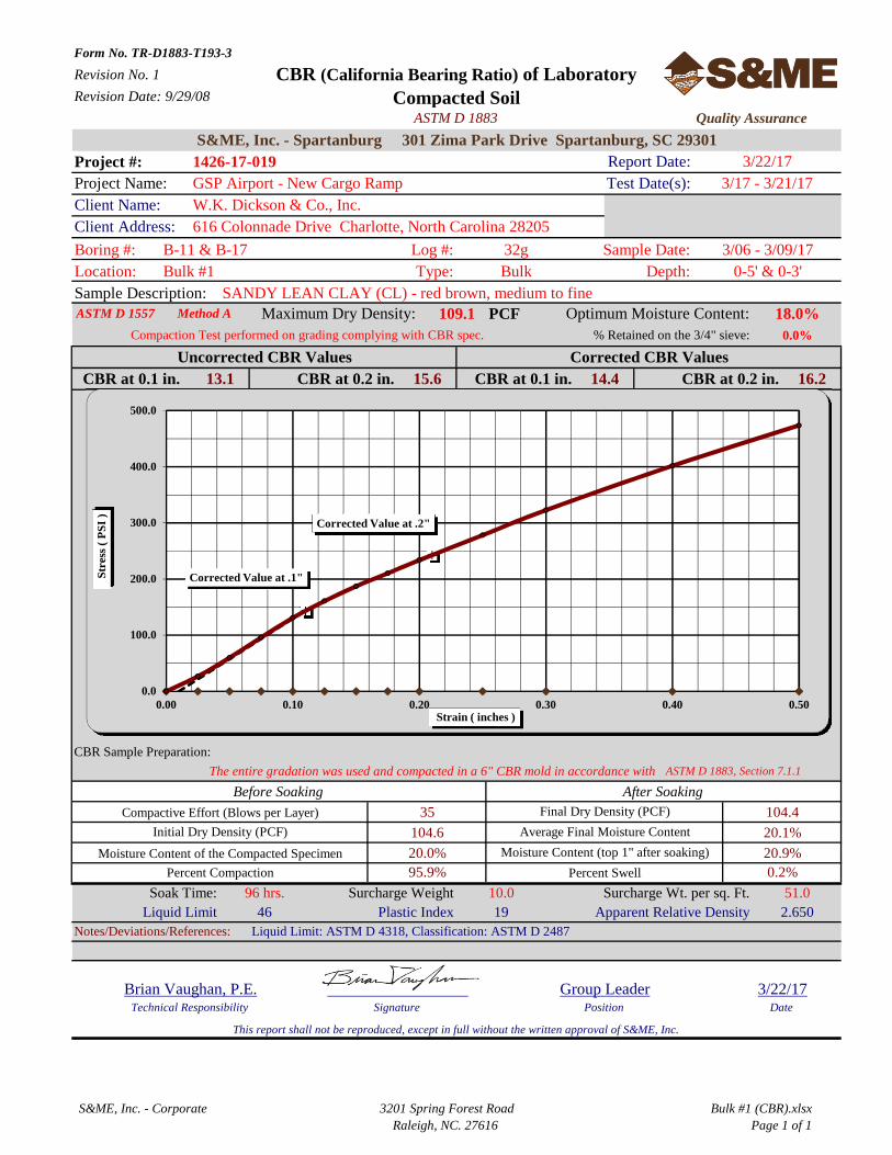
support characteristics and suitability for use as structural fill. The CBR specimens were remolded to 95
percent of the soil’s maximum dry density, based on the Modified Proctor (ASTM D 1557), in accordance
with the referenced FAA Advisory Circulars. This degree of compaction is not necessarily representative of
the existing/in situ condition; however, we will recommend that that subgrade soils be compacted to at
least this minimum compaction threshold during site preparation and fill placement.
Appendix III contains the individual laboratory test reports and Summary of Laboratory Test Data table,
and the results are summarized below:
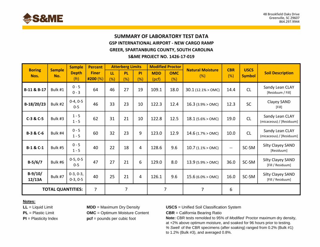
♦ The composite samples varied in soil classification from sandy clay (CL), sandy clay (CL) with mica,
clayey sand (SC), and silty-clayey sand (SC-SM). These soil classifications generally represented
the majority of the site soils sampled in the upper 3 to 5 feet;
♦ Percent fines for the CL soils ranged from 60 to 64 percent, and the percent fines for the SC and
SC-SM soils ranged from 40 to 47 percent;
♦ Plasticity Index for the CL soils ranged from 9 to 19 percent, and the Plasticity Index for the SC
and SC-SM soils ranged from 4 to 10 percent;
♦ Modified Proctor Maximum Dry Density (MDD) for the CL soils ranged from 109.1 to 123.1 pcf,
and the MDD for the SC and SC-SM soils ranged from 122.3 to 129.0 pcf;
♦ Modified Proctor Optimum Moisture Content (OMC) for the CL soils ranged from 12.5 to 18.0
percent, and the OMC for the SC and SC-SM soils ranged from 8.0 to 12.4 percent;
♦ In situ Moisture Content for the CL soils ranged from 14.6 to 30.1 percent (roughly 2 to 12
percent over OMC), and the in situ Moisture Content for the SC and SC-SM soils ranged from 13.9
to 16.3 percent (roughly 1 to 6 percent over OMC);
♦ CBR values for the CL soils ranged from approximately 10 to 19 percent, and the CBR values for
the SC and SC-SM soils ranged from approximately 12 to 36 percent;
♦ The percent swell of the CBR specimens (after soaking for 96 hours) ranged from 0.2 percent to
1.2 percent, and averaged 0.8 percent for the six CBR specimens tested.
4.0 Site Grading Recommendations
The boring data indicates most of the site is underlain by some existing fill soils associated with previous
grading of the pad approximately 15 years ago. Primary geotechnical considerations for this project
include:
♦ Installation of a functioning drainage system to help mitigate the destabilizing effects of perched
water (trapped in the relatively thin layer of soil above shallow, very dense PWR/rock);
♦ Thorough evaluation of existing fill soils and stability of exposed silty/clayey soils in both
excavation and fill placement areas;
♦ The potential for difficult excavation conditions due to very shallow partially weathered rock
(PWR) and mass rock, particularly for deep utility trench excavations and grading for the entrance
driveway from Gateway Drive; and
♦ Selection of an appropriate CBR value for design of the site pavements, based on highly variable
field and laboratory CBR test results.
Page 16
Geotechnical Exploration Report
GSP Airport – New Cargo Ramp
Greer, Spartanburg County, South Carolina
S&ME Project No. 1426-17-019
April 3, 2017 12
Our experience indicates silty/clayey soils can become soft and unstable, especially after heavy rainfall and
rubber-tired traffic, requiring some undercutting and/or stabilization with crushed stone. The sampled fill
and residual soils generally appear suitable to be left in place for building and pavement support;
however, the stability of these soils varies greatly with prevailing weather conditions (precipitation and
temperature) at time of grading. With any previously disturbed site, some undercutting of existing fill
should be expected.
Although a final grading plan has not yet been developed, we understand proposed grades will likely be
very close to the current topography of the graded pad. The borings indicated partially weathered rock
(PWR) and mass rock are very shallow in several areas of the site, and difficult excavation conditions could
be encountered (depending on selected final grades).
The following presents our geotechnical recommendations regarding grading for the proposed Cargo
Ramp apron, warehouse/distribution building, and associated pavements. When reviewing this
information, please remember portions of the site have been previously disturbed, developed, and/or
graded. Our experience with sites such as this indicates unexpected conditions, such as deposits of
unsuitable existing fill or low consistency natural soils, could exist between the boring locations and
unexplored areas of the site. Accordingly, field engineering evaluations during construction will be very
important and modifications to our recommendations could be required.
The design and construction team should understand our recommendations are based on the premise
that an S&ME representative will be on-site to observe and document site work, including site
preparation, proofrolling, undercutting, excavation, fill placement, and to perform density testing of fills.
Proper site preparation and maintenance is critical to providing time- and cost-efficient construction. Our
observations and tests can be a vital component in improving the performance and efficiency of the site
work.
Pavements, base course materials, and sub-base materials should be designed and constructed in
accordance with the referenced FAA Advisory Circular 150/5370-10G, “Standards for Specifying
Construction of Airports” (dated July 21, 2014), or otherwise updated.
Site Preparation
Stripping
Site preparation should begin with the removal of all unsuitable surface materials. Stripping should
extend at least 5 to 10 feet outside the proposed construction limits, where practical. This would include
the removal of surface vegetation, organic laden topsoil, and any unstable near-surface soils. Across the
graded pad area, the topsoil thickness generally varied from about 2 to 4 inches; however, in the
perimeter drainage swales, the topsoil thickness was thicker (on the order of 5 to 8 inches) and will require
additional mucking prior to fill placement. In the wooded area (around boring B-26), we anticipate
stripping depths will be greater to remove tree root systems.
Drainage
At the time of the exploration, we observed the upper surficial soils were notably moist from recent
rainfall. We anticipate this condition is indicative of currently poor drainage, caused by a relatively flat
Page 17
Geotechnical Exploration Report
GSP Airport – New Cargo Ramp
Greer, Spartanburg County, South Carolina
S&ME Project No. 1426-17-019
April 3, 2017 13
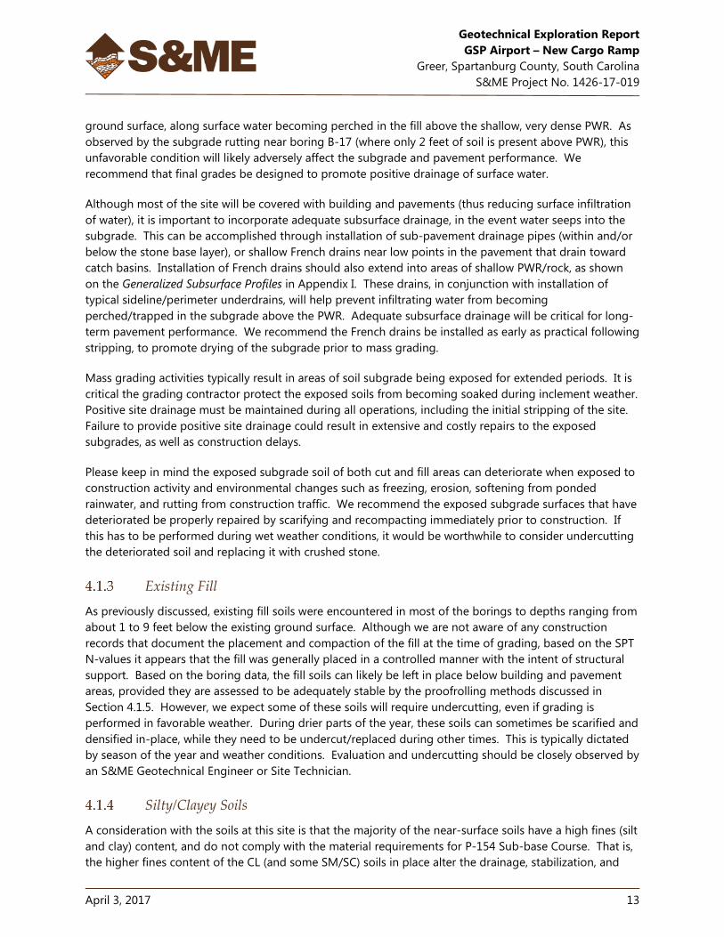
ground surface, along surface water becoming perched in the fill above the shallow, very dense PWR. As
observed by the subgrade rutting near boring B-17 (where only 2 feet of soil is present above PWR), this
unfavorable condition will likely adversely affect the subgrade and pavement performance. We
recommend that final grades be designed to promote positive drainage of surface water.
Although most of the site will be covered with building and pavements (thus reducing surface infiltration
of water), it is important to incorporate adequate subsurface drainage, in the event water seeps into the
subgrade. This can be accomplished through installation of sub-pavement drainage pipes (within and/or
below the stone base layer), or shallow French drains near low points in the pavement that drain toward
catch basins. Installation of French drains should also extend into areas of shallow PWR/rock, as shown
on the Generalized Subsurface Profiles in Appendix I. These drains, in conjunction with installation of
typical sideline/perimeter underdrains, will help prevent infiltrating water from becoming
perched/trapped in the subgrade above the PWR. Adequate subsurface drainage will be critical for long-
term pavement performance. We recommend the French drains be installed as early as practical following
stripping, to promote drying of the subgrade prior to mass grading.
Mass grading activities typically result in areas of soil subgrade being exposed for extended periods. It is
critical the grading contractor protect the exposed soils from becoming soaked during inclement weather.
Positive site drainage must be maintained during all operations, including the initial stripping of the site.
Failure to provide positive site drainage could result in extensive and costly repairs to the exposed
subgrades, as well as construction delays.
Please keep in mind the exposed subgrade soil of both cut and fill areas can deteriorate when exposed to
construction activity and environmental changes such as freezing, erosion, softening from ponded
rainwater, and rutting from construction traffic. We recommend the exposed subgrade surfaces that have
deteriorated be properly repaired by scarifying and recompacting immediately prior to construction. If
this has to be performed during wet weather conditions, it would be worthwhile to consider undercutting
the deteriorated soil and replacing it with crushed stone.
Existing Fill
As previously discussed, existing fill soils were encountered in most of the borings to depths ranging from
about 1 to 9 feet below the existing ground surface. Although we are not aware of any construction
records that document the placement and compaction of the fill at the time of grading, based on the SPT
N-values it appears that the fill was generally placed in a controlled manner with the intent of structural
support. Based on the boring data, the fill soils can likely be left in place below building and pavement
areas, provided they are assessed to be adequately stable by the proofrolling methods discussed in
Section 4.1.5. However, we expect some of these soils will require undercutting, even if grading is
performed in favorable weather. During drier parts of the year, these soils can sometimes be scarified and
densified in-place, while they need to be undercut/replaced during other times. This is typically dictated
by season of the year and weather conditions. Evaluation and undercutting should be closely observed by
an S&ME Geotechnical Engineer or Site Technician.
Silty/Clayey Soils
A consideration with the soils at this site is that the majority of the near-surface soils have a high fines (silt
and clay) content, and do not comply with the material requirements for P-154 Sub-base Course. That is,
the higher fines content of the CL (and some SM/SC) soils in place alter the drainage, stabilization, and
Page 18
Geotechnical Exploration Report
GSP Airport – New Cargo Ramp
Greer, Spartanburg County, South Carolina
S&ME Project No. 1426-17-019
April 3, 2017 14
support characteristics desired for sub-base materials. These soils can generally provide suitable
structural support, but they are sensitive to moisture during grading. This could require close moisture
control, and compaction using both sheepsfoot and pneumatic tire roller type compactors. This can be a
significant consideration if grading is performed during unfavorable weather. Also, these types of soil
tend to degrade quickly, especially when heavy equipment operates on the exposed subgrade during wet
weather conditions. Depending on prevailing weather, drying/scarifying these soils with disc harrows or
mixing crushed stone with them could be needed.
Proofrolling and Subgrade Evaluation
After stripping and removing any near-surface unstable soils (and prior to planned fill placement), the
exposed subgrade should be evaluated by the Geotechnical Engineer to help assess that unsuitable
materials have been removed. Although the split-spoon samples and SPT data suggest the existing fill
appears generally suitable for building and pavement support, our experience indicates the
consistency/quality of fill is inherently variable, and some areas might not be suitable for structural
support. This variability warrants thorough evaluation of the site subgrade prior to fill placement and
building/pavement construction.
To aid the Engineer during the evaluation, the exposed subgrade should be proofrolled with a heavily
loaded tandem-axle dump truck or similar rubber-tired equipment. Proofrolling helps reveal the presence
of disturbed, unstable or otherwise unsuitable surface materials. Areas that are judged to contain
unsuitable soils or that visually yield or “pump”, indicating softer unstable zones, should be undercut or
stabilized in-place as recommended by the Geotechnical Engineer. Depending on the results of the
proofrolling, some shallow test pits and/or hand auger borings with DCP testing could be needed to help
further evaluate the suitability of the subsurface soils.
Proofrolling should only be performed during favorable weather so that otherwise suitable subgrade soils
are not disturbed. The borings indicated the surficial soils were moist, so the upper soils should be
allowed to dry (or be scarified and recompacted) prior to proofrolling and evaluation. After topsoil
stripping, we anticipate the subgrade soils will begin to dry and stabilize if exposed to warm dry weather
(and then protected from seeping/standing water following rain, as recommended).
Where undercutting is recommended (if required, based on observations during proofrolling), it should
extend laterally beyond the building limits to a distance of 5 feet or the undercut depth, whichever is
greater. Undercutting should extend vertically down to stable residual soil or partially weathered rock and
backfilled to plan subgrade elevation with well-compacted structural fill. We recommend having a
sufficient budget contingency to account for repair or improvement of these subgrades by undercutting
or other stabilization measures.
As noted above, any low-lying areas beyond the graded pad (including the perimeter swales, and the
drainage swale between Taxiway Lima and the service driveway) should be cleaned of any loose sediment
deposits, and then compacted/densified to create a stable subgrade. Thorough subgrade preparation
and evaluation (by proofrolling and other means) of these sideline soil areas, and subsequent filling with
compacted structural fill, will be very important to create a uniform pavement subgrade and help avoid
developing a possible differential settlement condition.
Page 19
Geotechnical Exploration Report
GSP Airport – New Cargo Ramp
Greer, Spartanburg County, South Carolina
S&ME Project No. 1426-17-019
April 3, 2017 15
Excavation
The boring data indicates excavation will primarily extend through low to high consistency fill, residual
soils, PWR, and possibly mass rock (depending on selected final grades for utilities and the entrance
driveway). As previously discussed, the borings encountered PWR and rock at depths as shallow as 1 to 2
feet below the surface (near Elevations 957 and 958 feet within the graded pad), although the PWR/rock
depths were variable across the site. For the southern entrance driveway, boring B-26 (located in the
currently wooded area) encountered shallow refusal at a depth of approximately 4.5 feet, near El. 963 feet.
Therefore, difficult excavation conditions should be anticipated and budged accordingly.
Please keep in mind rock in a weathered, boulder, and massive form varies very erratically in depth and
location in the Piedmont Geologic Province. Also, rock lenses and boulders could be encountered within
the PWR zone. Accordingly, there is always a potential that refusal materials could be encountered at
shallower depths in unexplored areas of the site. Prior to construction, we recommend performing several
test pits in the planned excavation areas near the boring locations that encountered PWR and refusal to
help evaluate the anticipated excavation difficulty. If these test pits are performed in the building area,
they should be backfilled with compacted crushed stone.
The following presents our comments regarding excavation of these various materials based on our
experience.
Low To High Consistency Residual Soils
These materials can be excavated by routine earthmoving equipment. That is, mass excavation can be
accomplished by a bulldozer, moderately heavy front end loader, or bulldozer pushed scrapper. Local
excavation for shallow utility trenches can be accomplished by a heavy backhoe or tracked excavator.
Partially Weathered Rock
This material can normally be excavated by very hard ripping or diligently using a heavy front-end loader.
The PWR will cause difficulty to a conventional backhoe requiring the use of a heavy tracked excavator
operating with difficulty, with the possibility of some blasting or hand excavation using pneumatic tools
where boulders or rock lenses are present.
Massive Rock
Refusal to auger advancement was encountered by many of the borings and should be expected
throughout the site, depending on selected final grades. Excavation below the auger refusal level in the
borings should be expected to require the use of rock excavation measures, including pneumatic tools,
hoe ram attachments, and/or blasting. Because of the high potential for encountering massive rock
during local/trench excavation (and possibly mass grading for the entrance driveway), we suggest
the following clauses for rock definition be considered for use in preparing project specifications:
Rock Excavation - Any material that cannot be excavated with a single tooth ripper drawn by a
crawler tractor having a minimum flywheel power rated at not less than 305 horsepower
(Caterpillar D-8N or equivalent), occupying an original volume of at least one cubic yard or more,
and requires blasting or use of pneumatic hammers.
Trench Excavation - Any material which cannot be excavated with a Caterpillar 345 or equivalent,
occupying an original volume of at least ½ cubic yard or more, and which requires blasting or
other rock excavation methods.
Page 20
Geotechnical Exploration Report
GSP Airport – New Cargo Ramp
Greer, Spartanburg County, South Carolina
S&ME Project No. 1426-17-019
April 3, 2017 16
Because rock excavation is a high potential for this site, an important part of the grading contract
negotiations is the method used to measure the volume of any rock excavated. Our experience has found
that excavation of PWR and rock is dependent upon the equipment and methods used by the contractor
and the diligence used for excavation of this material. These items should be agreed upon and
understood by all parties prior to grading.
All excavations should be sloped or shored in accordance with local, state, and federal regulations,
including OSHA (29 CFR Part 1926) excavation trench safety standards. The contractor is solely
responsible for site safety. This information is provided only as a service and under no circumstances
should S&ME be assumed to be responsible for construction site safety.
Fill Placement and Compaction
After excavation and subgrade preparation activities are complete (and any necessary undercutting), at-
grade areas and areas requiring fill placement should be moisture-conditioned and densified/compacted
in-place to at least 95 percent of the soil’s maximum dry density, as determined by a laboratory Modified
Proctor compaction test (ASTM D-1557). Then, areas requiring fill placement should be raised to their
design subgrade elevation with soil free of deleterious materials. Any PWR/rock fragments within the new
fill should have a maximum particle size less than 4 inches in diameter. The fill should be uniformly
spread in 6- to 8-inch thick loose lifts and be compacted to at least 95 percent of the soil’s maximum dry
density, as determined by a laboratory Modified Proctor compaction test (ASTM D-1557). The moisture
content should be controlled at plus to minus 3 percent of optimum. Stricter moisture control could be
required to achieve satisfactory compaction of the silty/clayey soils at this site.
Fill placement should be observed by a qualified Materials Technician working under the general direction
of the Geotechnical Engineer. In addition to this visual evaluation, the Technician should perform a
sufficient number of in-place field density tests to confirm the required degree of compaction is attained.
Periodic field “check plugs” should be performed to help determine the correct Proctor data to use.
Use of Excavated Soils as Fill
We expect the existing fill and residual soils should be adaptable for use as structural fill for building and
pavement areas. Based on our observation of the split-spoon samples from the borings, we anticipate
much of the existing fill (minus any debris or deleterious material) will likely be suitable for re-use as
structural fill, although some moisture adjustment could be required to achieve the recommended degree
of compaction. From the laboratory testing, we anticipate some drying of the upper soils will be needed,
as the in-situ moisture content of each of the seven bulk samples was higher than the Optimum Moisture
Content (OMC) determined by its Modified Proctor test. For four of the seven samples, the in-situ
moisture content was 6 to 12 percent higher than the OMC, indicating significant drying effort could be
required. Existing fill materials should be evaluated by our technician during excavation to assess whether
they are suitable for possible re-use. Soils not suitable for use as structural fill can likely be used as fill for
landscaped or other “green” areas.
Most of the PWR will also be suitable for use as structural fill, provided it can be broken down to the
recommended maximum particle size. This material is typically excavated in the form of blocks. Normally,
heavy sheepsfoot type compaction equipment can suitably pulverize these blocks into soil sized to 4-inch
diameter particles.
Page 21
Geotechnical Exploration Report
GSP Airport – New Cargo Ramp
Greer, Spartanburg County, South Carolina
S&ME Project No. 1426-17-019
April 3, 2017 17
The moisture content of the on-site soil, especially those near the surface, will fluctuate with weather
conditions. Depending upon the time grading begins, some drying or wetting could be required to
achieve the required degree of compaction.
Use of Off-Site Borrow Materials as Fill
Imported fill used for site grading should consist of a clean (free of organics and debris), low plasticity soil
(Liquid Limit less than 50, Plasticity Index less than 25), and be evaluated by a Geotechnical Engineer prior
to use. However, to truly gain the benefits of using “select” fill material for improved pavement subgrade
support, we recommend refining the following physical characteristic requirements:
♦ Liquid Limit less than 40, Plasticity Index less than 10;
♦ Percent fines less than 40 percent;
♦ Mica content less than 0.5 percent by weight; and
♦ Modified Proctor maximum dry density greater than 120 pounds per cubic foot.
Note the gradation and plasticity requirements for Sub-Base material, per FAA Section P-154 of the
referenced Advisory Circulars, are more stringent than these values.
Fill Slopes
Although we anticipate only minor new fill across most of the graded pad, significant fill thickness (on the
order of 8 to 9 feet) will likely be required to extend the northeastern side of the pad to accommodate the
length of the proposed building. This will entail extending the crest of the existing slope to the northeast,
and filling the existing drainage swale. Prior to grading the slope, the existing slope face should be
stripped of topsoil, and the bottom of the swale mucked of loose sediment/topsoil and evaluated for
stability. As the new fill slope is graded, the existing slope face should be “benched” in a stepped
configuration to promote a positive bond between the existing slope material and new fill (placed and
compacted in horizontal lifts as “structural fill”). The resulting slope face should be inclined no steeper
than 2H:1V (horizontal to vertical), and preferably flatter.
A similar condition is expected for the filling of the same deep swale near the entrance driveway (near
boring B-25), and filling of the sideline drainage swale along Taxiway Lima (for grading of the air-side
entrance to the cargo ramp area). Therefore, the recommendations for swale subgrade preparation,
benching, and fill placement apply for these slope/embankment areas as well.
Wet Weather Grading
During wet weather, special measures will be necessary for this site. These will include the following:
♦ Excavated ditches to help reduce rainwater runoff from flowing on to the construction area.
♦ The ground surface should be pitched to promote rainwater run-off and help prevent ponding of
surface water.
♦ The exposed ground surface should be sealed at the end of each work day (if inclement weather
is expected) to help reduce rainwater seepage into the soil.
♦ The Contractor should have equipment, such as disk harrows, to help scarify and dry the wet soil.
Some spreading of the soil and aerating could be needed.
♦ Additional undercutting of unstable soil will be needed during wet weather.
Page 22
Geotechnical Exploration Report
GSP Airport – New Cargo Ramp
Greer, Spartanburg County, South Carolina
S&ME Project No. 1426-17-019
April 3, 2017 18
5.0 Structure Recommendations
Spread Foundations
The following footing design recommendations are based on the assumption that our Geotechnical
Engineer (or the Engineer’s representative Field Technician) will be on-site during grading and
construction activities to observe footing excavations and to assess that appropriate bearing soils are
present, as well as to evaluate foundation bearing surfaces are properly prepared prior to footing
construction.
Provided the previous recommendations (regarding site preparation, proofrolling, subgrade evaluation
and preparation, and new fill placement) are followed, shallow foundations consisting of conventional
spread footings may be used to support the planned single-story building. The foundations can be
designed and sized using a maximum net allowable soil bearing pressure of 3000 psf, for foundations
bearing in approved residual soil or well-compacted fill. Although a higher bearing pressure is available
for foundations bearing in PWR (typically 4000+ psf), portions of the building will be supported by 10+
feet of fill/residual soil, so the lower value is recommended to help avoid a potential differential
settlement condition.
The building foundations will span between areas of fill, residual soils, and PWR (and possibly refusal
material, massive rock). To help prevent/reduce potential differential settlements, we recommend
foundations not bear directly on massive rock. If encountered within the foundation excavation,
massive rock should be over-excavated at least one foot below the design bearing level, and a one-
foot thick layer of well-compacted fill should be placed over the rock.
The foundations should bear at least 18 inches below grade so they will not be adversely affected by frost
penetration and to develop the design bearing pressure. Continuous strip footings should not be less
than 24 inches wide and isolated column/pedestal footings should not be less than 36 inches wide. This
recommendation is made to help prevent a “localized” or “punching” shear failure condition which could
exist with very narrow footings. Also, the building foundations should be setback at least 10 feet from the
crest of any slope.
Foundation Construction Recommendations
Proper foundation construction procedures can enhance long-term foundation performance. We
recommend the following procedures for use during construction:
♦ All bearing surfaces should be cleaned of wet, loose or soft soils prior to the placement of
concrete or rebar;
♦ The foundation bearing surfaces must be observed and evaluated by our Geotechnical Engineer
or representative prior to placement of reinforcing steel or concrete. Often, excavation results in
disturbance to the bearing soils. Also, unsuitable soil not detected by the proofrolling evaluation
(such as cultivated soil below a relatively thin layer of fill, such as at borings B-16 and B-18) could
underlie some excavation areas. Some localized undercutting or stabilization of low consistency
soil with crushed stone could be necessary in some areas. The Engineer should identify such
areas and can make recommendations for the appropriate repair and/or stabilization;
Page 23
Geotechnical Exploration Report
GSP Airport – New Cargo Ramp
Greer, Spartanburg County, South Carolina
S&ME Project No. 1426-17-019
April 3, 2017 19
♦ Foundation concrete should be placed in the excavation the same day the foundations are
excavated. If an excavation is to remain open overnight, and there is a chance of rain, a 2- to 3-
inch thick mud mat of lean (2,000 psi) concrete can be placed in the bottom of the excavation to
protect the bearing soils. This will help limit the potential for additional excavation of wet,
softened soils which often results when excavations are exposed to inclement weather;
♦ Undercut excavations should be backfilled with ASTM No. 57 crushed stone under the
observation of the Geotechnical Engineer. It should be placed in maximum 1-foot thick lifts and
tamped thoroughly using a “Wacker Packer” or vibrating sled style compactor; and
♦ Foundation excavations should be “clean cut” and concrete should be placed “neat”, without the
use of forms, where possible.
Settlement
Based on the anticipated structural loads and our experience with similar subsurface conditions, and
sizing the foundations based on the recommended bearing pressure, we estimate maximum column
settlement (due to the weight and live loads from the structure) to be less than 1 inch, with differential
settlement to be on the order of ½ inch.
Floor Slab
The building’s floor slab may be soil supported, provided the recommendations discussed in the sections
entitled 4.1 Site Preparation and 4.3 Fill Placement and Compaction are followed. Based on the boring
results and our experience, a modulus of subgrade reaction (k) of 130 pci (based on the 30-inch diameter
plate method) may be used for floor slab design, provided that a recommended 6-inch thick layer of
crushed stone is installed to separate the floor slab from the compacted subgrade soils. The crushed
stone should consist of Macadam Base Course compacted to at least 100 percent of the material’s
standard Proctor maximum dry density. This layer will help reduce construction downtime during wet
weather conditions and will provide a good leveling course. Also, it will be very important to provide
proper compaction of the subgrade soils and proper drainage around the floor slab to help reduce the
migration of rainwater runoff below the floor slab.
It is our opinion, based on the anticipated floor elevation (and assumed installation of a subgrade
drainage system), a plastic vapor retarder is not required beneath the floor slab for geotechnical
considerations. However, based on our observation of the moist subgrade conditions and potential for
water to become perched/trapped in the soil zone above the dense PWR layer, installation of a vapor
retarder could help prevent moisture transmission through the slab. However, the need for a vapor
retarder will depend on the floor covering design, and the local building code for the type of structure.
Seismic Conditions
Using the general procedure of the International Building Code (IBC), 2015 Edition, Section 1613.3 (which
references Chapter 20 of ASCE 7), the boring data and our experience, it is our interpretation this site has
a seismic Site Class of C. There are no active earthquake fault zones within close proximity to the general
area and thus the site vicinity is not known to be subject to concerns of any major geologic hazards such
as significant ground shaking, liquefaction, seismically induced slope failures, etc.
Page 24
Geotechnical Exploration Report
GSP Airport – New Cargo Ramp
Greer, Spartanburg County, South Carolina
S&ME Project No. 1426-17-019
April 3, 2017 20
Retaining Walls
As previously discussed, retaining walls will be needed for the building’s loading dock walls, and also
possibly for the “blast wall” in the northern corner of the pad. We assume these walls will be constructed
as cast-in-place (CIP) concrete retaining walls. CIP concrete retaining walls must be capable of resisting
lateral earth pressures that will be imposed on them. Lateral earth pressures to be resisted by the walls
will be partially dependent upon the method of construction. Assuming the walls are relatively rigid and
structurally braced against rotation, they should be designed for a condition approaching the "at-rest"
lateral pressure. However, in the event the walls are free to deflect (about ½ to 1 inch for a 10-foot high
wall) during backfilling, as for any exterior walls that are not restrained or rigidly braced, the "active"
pressure conditions will be applicable for design. The following lateral earth pressure parameters are
recommended for design, based on our experience, and assuming a level backfill and a frictionless wall.
Table 5-1: Lateral Earth Pressure Parameters
Lateral Earth Pressure Parameter Value
At-Rest Coefficient (Ko) 0.53
Active Coefficient (KA) 0.36
Passive Coefficient (KP) 2.8
Unit Weight Of Soil (Moist) 115 pcf
Friction Factor For Foundations and Bearing Soils 0.35
The recommended lateral earth pressure coefficients/parameters do not consider the development of
hydrostatic pressure from such things as rainwater runoff or leaking utilities behind the earth retaining
wall structures. As such, positive wall drainage must be provided for all earth retaining structures. These
drainage systems can be constructed of open-graded washed stone isolated from the soil backfill with a
geosynthetic filter fabric and drained by perforated pipe or weepholes. As an alternative, several wall
drainage products are produced specifically for this application. Lateral earth pressures arising from
surcharge loading or slopes above the wall should be added to the above earth pressures to determine
the total lateral pressure.
The soil backfill placed behind retaining walls and for fill placed in the passive zone should be placed and
compacted in accordance with Section 4.3. We caution that operating compaction equipment directly
behind the retaining structures can create lateral earth pressures far in excess of those recommended for
design. Therefore, bracing of the walls will be needed during backfilling operations.
6.0 Pavement Subgrade Recommendations
Pavement thickness design is primarily based on the supporting subgrade soils, drainage characteristics,
and traffic loading and frequencies of vehicles/aircraft. We understand the proposed pavement section
thicknesses for the ramp apron and driveway will be designed by others. As such, we are not aware of the
anticipated vehicle loading and frequency information, and other input parameters (desired lifetime,
terminal serviceability rating, statistical controls, etc.). We are providing recommendations for pavement
subgrade support value(s) in the section below.
Page 25
Geotechnical Exploration Report
GSP Airport – New Cargo Ramp
Greer, Spartanburg County, South Carolina
S&ME Project No. 1426-17-019
April 3, 2017 21
Subgrade Modulus Values
As previously discussed, the exposed soil at final subgrade elevation should be compacted to densify the
subgrade surface (both prior to, and during, fill placement operations). Per FAA Section P-152 for
Excavation/Subgrade, the Modified Proctor (per ASTM D1557) should be used for comparison, based on
the aircraft weights exceeding 60,000 pounds. We recommend the subgrade soil (and structural fill) be
compacted to at least 95 percent of its Modified Proctor Maximum Density. This densification will help
increase the available subgrade modulus k values of the exposed subgrade soil. It should be noted that
the laboratory CBR testing we performed on bulk samples of the site soils consisted of Modified Proctor
compaction testing (ATM D1557) to comply with the intent of FAA Section P-152. Because our
recommendations are based on the results of the laboratory Modified Proctor/CBR tests, it is critical for
the subgrade and fill placed during grading be compacted to at least this same compactive effort (and
preferably higher).
As indicated by the laboratory CBR test results and field Kessler DCP test results, the soil subgrade
modulus (k) values vary widely for the different soil types at the anticipated subgrade elevation. Because
there appears to be a general demarcation in the soil conditions northwest of the proposed building (for
the air-side ramp apron and taxiway entrance) versus the soil conditions southeast of the building (for the
land-side apron, parking, and driveway pavements), we will address the two areas separately.
For the northwestern air-side apron and taxiway entrance, refer to the Kessler DCP values obtained near
borings C-1 through C-6, and borings B-1 through B-15 (in Appendix II). A very conservative approach
would be to use the lowest measured value (k of 73 pci, correlated from a CBR of 3.3 percent at boring B-
6); however, this approach might not be deemed economical. Alternatively for a slightly less conservative
approach, the subgrade modulus used for design could be selected to represent the majority of soils
at/below final subgrade elevation. Thus, it is our opinion to use a slightly higher value, such as a
subgrade modulus k of 170 pci (correlated from a CBR of 10.0 percent). Of the fifty-four Kessler
subgrade modulus values measured in the northwestern air-side apron area, forty-seven (87 percent)
were greater than or equal to this value. This value accounts for the less favorable subgrade support
characteristics provided by clayey/silty (CL) soils present near final design subgrade elevation across much
of the site. The six laboratory CBR values had a lower-bound threshold of 10.0 percent, indicating the site
soils can exhibit the suggested subgrade modulus if properly compacted.
For the southeastern land-side pavements, refer to the Kessler DCP values obtained near borings C-8 and
B-16 through B-26 (in Appendix II). In general, the Kessler values for this area were notably lower on
average, as compared to the air-side apron area described above. Even selecting a conservatively modest
subgrade modulus k value of 100 pci (correlated from a CBR of 5.0 percent) accounts for only
seventeen of the twenty-six values (65 percent). However, we conclude that many of the lower values
were likely due to the high moisture content and instability of the wet surficial soils at the time of the
investigation (such as near boring B-17, and other areas with standing water, for example). With proper
drying and compaction, and the resulting stabilization, we expect a larger proportion of the soils for the
southeastern land-side pavements would exhibit a minimum k value of 100 pci (CBR of 5.0 percent).
The conservative recommendation in the paragraph above applies for existing fill soils on the graded pad
that will be exposed near final subgrade elevation. For areas that will receive at least 3 feet of new
compacted fill, or areas (such as the high wooded area near boring B-26) that will be excavated down to
stable residual soil, the higher subgrade modulus k of 170 pci (CBR of 10.0 percent) would apply.
Page 26
Geotechnical Exploration Report
GSP Airport – New Cargo Ramp
Greer, Spartanburg County, South Carolina
S&ME Project No. 1426-17-019
April 3, 2017 22
By selecting a subgrade modulus k value that is greater than the observed low-point threshold, it is
important to recognize the risk (although manageable) associated with this design methodology. Some
areas of pavement subgrade, including areas not explored by the widely spaced borings of this
investigation, could exhibit pavement support characteristics below the k value used in design. To help
mitigate the risk of compromised pavement performance in these statistically lower-bound cases, it is
important that the site preparation and grading recommendations be followed, and the grading and
pavements be constructed in strict accordance with the project specifications (and referenced FAA
Advisory Circulars). As a component of the construction-phase quality control program, we recommend
performing numerous Kessler DCP tests near final subgrade elevation, to check that the minimum design
values for subgrade modulus have been achieved.
General Guidelines
The long-term performance of rigid and flexible pavements will be influenced by a number of factors
including the condition of the subgrade soils at the time of pavement installation, installed thicknesses
and compaction, and properly functioning drainage. Areas adjacent to pavements (embankments,
ditching, etc.) which can drain water should be designed to help reduce water seepage below the
pavements. This may require the use of French drains and underdrains, as previously discussed.
Sufficient testing and monitoring should be performed during pavement installation to confirm that the
required thickness, density, and quality requirements of the specifications are followed. Typically, low
safety factors are used for pavement design. Therefore, it is important that all components of design are
properly installed and that the expected traffic is not exceeded. We recommend against installing
pavements during wet weather, as it will significantly reduce their performance.
7.0 Limitations of Report
This report has been prepared in accordance with generally accepted geotechnical engineering practice
for specific application to this project. The conclusions and recommendations in this report are based on
the applicable standards of our practice in this geographic area at the time this report was prepared. No
other warranty, expressed or implied, is made.
The analyses and recommendations submitted herein are based, in part, upon the data obtained from the
subsurface exploration. The nature and extent of variations between the borings will not become evident
until construction. If variations appear evident, then we will re-evaluate the recommendations of this
report. In the event that any changes in the nature or design of the proposed Cargo Ramp building and
pavements are planned, the conclusions and recommendations contained in this report will not be
considered valid unless the changes are reviewed and conclusions modified or verified in writing.
We recommend that S&ME be provided the opportunity to review the final design plans and
specifications in order that earthwork recommendations are properly interpreted and implemented.
Modifications to our recommendations could be required, depending on selected final grades.
Because of the variable nature of the subsurface conditions and the potential for difficult excavation, we
recommend conducting a pre-construction meeting with W.K. Dickson, GSP, the Contractor, and a
representative of our firm. During this meeting, the recommendations in this report should be discussed
with respect to constructability and how prevailing weather conditions will significantly affect the site soils.
Page 27
APPENDIX
Appendix I - Figures
Boring Location Plans (7) – Figures 1 thr. 7
Generalized Subsurface Profiles (6) – Figures 8 thr. 13
Photographs of Field Conditions (3 pages)
Appendix II – Field Data
Legend to Soil Classification and Symbols
Soil Test Boring Logs (37)
Kessler DCP Test Data Tables (4)
Field Test Procedures
Appendix III – Laboratory Testing
Summary of Laboratory Test Data
Laboratory Test Reports (20)
Page 28
APPENDIX I
FIGURES
Boring Location Plans (7) – Figures 1 thr. 7
Generalized Subsurface Profiles (6) – Figures 8 thr. 13
Photographs of Field Conditions (3 pages)
Page 29
SCALE:
CHECKED BY:
DRAWN BY:
DATE: PROJECT NO.: 1426-17-019
FIGURE NO.BORING LOCATION PLANW.K. Dickson Schematic Plan
GSP Airport – New Cargo RampGreer, Spartanburg County, South Carolina
As Shown
GMT
March 2017
1LTF
Reference: “Preliminary Cargo Ramp Schematic” Plan, provided by W.K. Dickson (dated 2/15/2017)
APPROXIMATE BORING LOCATIONS
: Pavement Area (with Coring)
: Pavement Area
: Building Area
Page 30
SCALE:
CHECKED BY:
DRAWN BY:
DATE: PROJECT NO.: 1426-17-019
FIGURE NO.BORING LOCATION PLANW.K. Dickson Schematic Plan with 2013 Spartanburg County GIS Overlay
GSP Airport – New Cargo RampGreer, Spartanburg County, South Carolina
As Shown
GMT
March 2017
2LTF
Reference: “Preliminary Cargo Ramp Schematic” Plan, provided by W.K. Dickson (dated 2/15/2017); and Spartanburg County GIS Website
APPROXIMATE BORING LOCATIONS
: Pavement Area (with Coring)
: Pavement Area
: Building Area
Drainage Swale
Drainage Swale
Drainage SwalesDrainage Swale
Service Road
Taxiway “Lima”
Shoulder
Existing FedEx Facility
Drainage Swale
Page 31
SCALE:
CHECKED BY:
DRAWN BY:
DATE: PROJECT NO.: 1426-17-019
FIGURE NO.BORING LOCATION PLAN2016 Google Earth Aerial Photograph
GSP Airport – New Cargo RampGreer, Spartanburg County, South Carolina
See Fig. 2
GMT
March 2017
3LTF
APPROXIMATE BORING LOCATIONS
: Pavement Area (with Coring)
: Pavement Area
: Building Area
Reference: Google Earth Website
Drainage Swale
Drainage Swale
Drainage SwalesDrainage Swale
Service Road
Taxiway “Lima”
Shoulder
Existing FedEx Facility
Drainage Swale
Page 32
SCALE:
CHECKED BY:
DRAWN BY:
DATE: PROJECT NO.: 1426-17-019
FIGURE NO.BORING LOCATION PLAN2005 Google Earth Aerial Photograph
GSP Airport – New Cargo RampGreer, Spartanburg County, South Carolina
See Fig. 2
GMT
March 2017
4LTF
APPROXIMATE BORING LOCATIONS
: Pavement Area (with Coring)
: Pavement Area
: Building Area
Reference: Google Earth Website
Observed Wet Area After Rainfall
(note difference in ground color)
(water in detention pond, following rain)
Page 33
SCALE:
CHECKED BY:
DRAWN BY:
DATE: PROJECT NO.: 1426-17-019
FIGURE NO.BORING LOCATION PLAN1994 Google Earth Aerial Photograph
GSP Airport – New Cargo RampGreer, Spartanburg County, South Carolina
See Fig. 2
GMT
March 2017
5LTF
APPROXIMATE BORING LOCATIONS
: Pavement Area (with Coring)
: Pavement Area
: Building Area
Reference: Google Earth Website
Possible Exposed Rock at Ground Surface
Page 34
SCALE:
CHECKED BY:
DRAWN BY:
DATE: PROJECT NO.: 1426-17-019
FIGURE NO.BORING LOCATION PLAN1983 USGS Topographic Map
GSP Airport – New Cargo RampGreer, Spartanburg County, South Carolina
See Fig. 2
GMT
March 2017
6LTF
APPROXIMATE BORING LOCATIONS
: Pavement Area (with Coring)
: Pavement Area
: Building Area
Reference: Google Earth Website, with Earth-Point Overlay
Drainage FeatureCreek
El. 285 m(935 ft)
Drainage Feature
El. 291 m(955 ft)
Page 35
SCALE:
CHECKED BY:
DRAWN BY:
DATE: PROJECT NO.: 1426-17-019
FIGURE NO.BORING LOCATION PLAN1958 USGS Topographic Map
GSP Airport – New Cargo RampGreer, Spartanburg County, South Carolina
See Fig. 2
GMT
March 2017
7LTF
APPROXIMATE BORING LOCATIONS
: Pavement Area (with Coring)
: Pavement Area
: Building Area
Reference: Google Earth Website, with Earth-Point Overlay
Creek
El. 920 ft
El. 940 ft
Approx. Average Current Ground Surface (El. 959 ft)
Drainage Feature
Page 36
938
940
942
944
946
948
950
952
954
956
958
960
962
JOB NO:
DATE:
N = Standard Penetration Test resistance value (blows per foot). The depicted stratigraphy is shown for illustrative purposes only. The actual subsurface conditions will vary between boring locations.
1426-17-019
3/29/17
EL
EV
AT
ION
(f
ee
t-M
SL
)
41
20
7
50/2"
14
BT @ 10'
N
HC
11
25
50/1"
67
50/3"
BT @ 10'
N
20
59
77
50/1"
50/1"
BT @ 10'
N
22
72
50/2"
50/2"
77
C-1
BT @ 11'
N
14
20
20
10
22
C-2
BT @ 11'
N
19
26
42
64
50/3"
C-3
BT @ 11'
N
9
9
6
8
12
C-4
BT @ 11'
N
29
40
53
27
72
C-5
BT @ 11'
N
28
45
44
70
44
C-6
BT @ 11'
N
Figure
X
Diagram: Generalized Subsurface Profile
Area: Taxiway Shoulder and Ramp Entrance
Project: GSP Airport - New Cargo Ramp
Location: Greer; Spartanburg County, South Carolina
938
940
942
944
946
948
950
952
954
956
958
960
962
SP/SM, Poorly-graded Sand with Silt
Aggregate Base CoursePartially Weathered Rock
Asphalt
Topsoil
Clayey Sand
Silty Sand
Sand
Sandy Clay
Sandy Silt
B-1 B-2
B-3
gtaylor
Text Box
Borings at Taxiway Shoulder & Ramp Entrance
gtaylor
Callout
Hatching Denotes Existing Fill
Page 37
938
940
942
944
946
948
950
952
954
956
958
960
962
Sandy Silt
JOB NO:
DATE:
N = Standard Penetration Test resistance value (blows per foot). The depicted stratigraphy is shown for illustrative purposes only. The actual subsurface conditions will vary between boring locations.
1426-17-019
3/30/17
EL
EV
AT
ION
(f
ee
t-M
SL
)
Diagram: Generalized Subsurface Profile
Area: North Half of Ramp Apron
Project: GSP Airport - New Cargo Ramp
Location: Greer; Spartanburg County, South Carolina
Figure
X
Clayey Sand Sandy Clay
Silty Sand
Partially Weathered Rock Topsoil
940
938
942
944
946
948
950
952
954
956
958
960
962
41
20
7
50/2"
14
BT @ 10'
N
B-1
HC
11
25
50/1"
67
50/3"
BT @ 10'
N
B-2
20
59
77
50/1"
50/1"
BT @ 10'
N B-3A
11
25
18
35
50/3"
BT @ 10'
N
B-4
HC
18
50/2"
29
17
50/2"
BT @ 10'
N
B-5
HC
25
50/1"
37
86
50/2"
BT @ 10'
N
B-6
HC
18
18
26
22
22
BT @ 10'
N
B-7
HC
14
20
14
50/1"
AR @ 6.5'BT @ 6.5'
N
B-8
8
10
6
7
10
BT @ 10'
N
B-3
gtaylor
Text Box
Borings at North Half of Ramp Apron
gtaylor
Callout
Hatching Denotes Existing Fill
Page 38
938
940
942
944
946
948
950
952
954
956
958
960
962
JOB NO:
DATE:
N = Standard Penetration Test resistance value (blows per foot). The depicted stratigraphy is shown for illustrative purposes only. The actual subsurface conditions will vary between boring locations.
1426-17-019
3/29/17
Diagram: Generalized Subsurface Profile
Area: South Half of Ramp Apron
Project: GSP Airport - New Cargo Ramp
Location: Greer; Spartanburg County, South Carolina
EL
EV
AT
ION
(f
ee
t-M
SL
)
Figure
X
940
942
938
944
946
948
950
952
954
956
958
960
962
HC
18
18
26
22
22
BT @ 10'
N
B-6
HC
14
20
14
50/1"
AR @ 6.5'BT @ 6.5'
N
B-7
8
10
6
7
10
BT @ 10'
N
B-8
17
51
50/4"
AR @ 5'BT @ 5'
N
B-9
HC 14
50/1"
AR @ 3'BT @ 3'
N
B-10
N
HC
16
22
18
14
4
12
6
BT @ 20'
B-11
HC 16
50/1"
B-12
AR @ 3'BT @ 3'
N
50/1"
B-13
AR @ 1.2'BT @ 1.2'
N
HC
30
23
19
10
50/1"
B-13A
AR @ 9.3'BT @ 9.3'
N
HC
23
50/5"
50/3"
B-14
AR @ 5'BT @ 5'
N
Sandy ClayClayey Sand
Silty Sand Silty Clay Partially Weathered Rock
TopsoilSandy Silt
gtaylor
Callout
Hatching Denotes Existing Fill
gtaylor
Text Box
Borings at South Half of Ramp Apron
Page 39
938
940
942
944
946
948
950
952
954
956
958
960
962
Sandy Clay
Sand
JOB NO:
DATE:
N = Standard Penetration Test resistance value (blows per foot). The depicted stratigraphy is shown for illustrative purposes only. The actual subsurface conditions will vary between boring locations.
1426-17-019
3/29/17
Diagram: Generalized Subsurface Profile
Area: Building Footprint
Project: GSP Airport - New Cargo Ramp
Location: Greer; Spartanburg County, South Carolina
938
940
Clayey Sand
Silty Sand Silty Clay
EL
EV
AT
ION
(f
ee
t-M
SL
)
Figure
X
942
944
946
948
950
952
954
956
958
960
962
Sandy Silt
Topsoil
Partially Weathered Rock
SP/SM, Poorly-graded Sand with Silt
HC
16
22
18
14
4
12
6
BT @ 20'
N
B-11
HC 16
50/1"
B-12
AR @ 3'BT @ 3'
N
50/1"
B-13
AR @ 1.2'BT @ 1.2'
N
HC
30
23
19
10
50/1"
B-13A
AR @ 9.3'BT @ 9.3'
N
HC
23
50/5"
50/3"
B-14
AR @ 5'BT @ 5'
N
HC
21
29
19
50/1"
B-15
AR @ 6.6'BT @ 6.6'
N
21
15
14
AR @ 6'BT @ 6'
N
B-16
9
50/2"
B-17
AR @ 3'BT @ 3'
N
11
18
50/0"
AR @ 5'BT @ 5'
N
B-18
HC
17
67
75
B-19
AR @ 6'BT @ 6'
N
29
50/2"
B-19A
AR @ 2.6'BT @ 2.6'
N
gtaylor
Text Box
Borings at Proposed Building Footprint
gtaylor
Callout
Hatching Denotes Existing Fill
Page 40
946
948
950
952
954
956
958
960
962
964
966
968
0 100 200 300 400 500 600 700 800 900 1,000 1,100 1,200 1,300
Clayey Sand
Sandy Silt
JOB NO:
DATE:
N = Standard Penetration Test resistance value (blows per foot). The depicted stratigraphy is shown for illustrative purposes only. The actual subsurface conditions will vary between boring locations.
APPROXIMATE DISTANCE ALONG PROFILE (feet)
Diagram: Generalized Subsurface Profile
Area: Southern Loading Dock/Parking and Entrance Drive
Project: GSP Airport - New Cargo Ramp
Location: Greer; Spartanburg County, South Carolina
Asphalt Pavement
Aggregate Base Course
Cement Treated Base CourseSand
Silty Sand
1426-17-019
3/29/17
EL
EV
AT
ION
(f
ee
t-M
SL
)
Sandy Clay Topsoil
Partially Weathered Rock
Figure
X
946
948
950
952
954
956
958
960
962
964
966
968
11
18
50/0"
AR @ 5'BT @ 5'
N
HC
17
67
B-19
N
AR @ 6'BT @ 6'
75
25
30
20
B-20
AR @ 6'BT @ 6'
N
21
50/5"
B-21
AR @ 3.5'BT @ 3.5'
N 12
50/2"
N
AR @ 3'BT @ 3'
HC
12
32
38
15
5
B-23
AR @ 10'BT @ 10'
N
11
N
50/5"
AR @ 3.6'BT @ 3.6'
B-24
27
72
B-25
N
AR @ 4'BT @ 4'
3
32
50/1"
B-26
AR @ 4.5'BT @ 4.5'
N
46
20
64
69
60
BT @ 11.2'
C-7
N 11
50/1"
AR @ 5'BT @ 5'
C-8
N
B-22B-18
gtaylor
Text Box
Borings at Southern Loading Dock & Entrance Drive
gtaylor
Callout
Hatching Denotes Existing Fill
Page 41
938
940
942
944
946
948
950
952
954
956
958
960
962
JOB NO:
DATE:
N = Standard Penetration Test resistance value (blows per foot). The depicted stratigraphy is shown for illustrative purposes only. The actual subsurface conditions will vary between boring locations.
1426-17-019
3/30/17
EL
EV
AT
ION
(f
ee
t-M
SL
)
HC
11
25
50/1"
67
50/3"
BT @ 10'
N
20
59
77
50/1"
50/1"
BT @ 10'
N
11
25
18
35
50/3"
BT @ 10'
N
HC
18
50/2"
29
17
50/2"
BT @ 10'
N
HC
25
50/1"
37
86
50/2"
BT @ 10'
N
HC
14
20
14
50/1"
AR @ 6.5'BT @ 6.5'
N
8
10
6
7
10
BT @ 10'
N
17
51
50/4"
AR @ 5'BT @ 5'
N
HC 14
50/1"
AR @ 3'BT @ 3'
N
HC 16
50/1"
B-12
AR @ 3'BT @ 3'
N
HC
23
50/5"
50/3"
B-14
AR @ 5'BT @ 5'
N
21
15
14
AR @ 6'BT @ 6'
N 9
50/2"
B-17
AR @ 3'BT @ 3'
N
11
18
50/0"
AR @ 5'BT @ 5'
N
25
30
20
B-20
AR @ 6'BT @ 6'
N
HC
12
32
38
15
5
B-23
AR @ 10'BT @ 10'
N
Diagram: Generalized Subsurface Profile
Area: North-South Axis/Diagonal
Project: GSP Airport - New Cargo Ramp
Location: Greer; Spartanburg County, South Carolina
Figure
X
940
938
942
944
946
948
950
952
954
956
958
960
962
B-10B-16B-18
Clayey Sand
Silty Sand
Sandy Clay TopsoilSandy Silt
Silty Clay Partially Weathered Rock
B-9
B-7
B-8
B-4 B-5
B-3A
B-2
B-3
gtaylor
Text Box
Borings Along North-South Axis Diagonal
gtaylor
Callout
Hatching Denotes Existing Fill
Page 42
GSP Airport - New Cargo Ramp: Photographs from Field Exploration (March 6-9, 2017), Pg. 1 of 3
S&ME Project No. 1426-17-019
Building Pad Area; Drill Rig at B-12 (facing north)
Kessler DCP Testing at B-21 (facing southwest)
Rutting of wet subgrade following rainfall, near B-17 (facing northeast)
B-17 flag
Standing water following rainfall, near B-24 (facing east)
B-24 flag
Page 43
GSP Airport - New Cargo Ramp: Photographs from Field Exploration (March 6-9, 2017), Pg. 2 of 3
S&ME Project No. 1426-17-019
Catch basin (drains toadjacent Detention Pond)
Drainage swales along south end of site (facing northeast)
Drainage Swale
Drainage swale at slope toe along east end of site (facing northwest)
Drainage Swale
Drainage Swale
B-19A flag;Ground Surf. Elev.
at swale bottomnear 951 ft
Ground Surf. Elev.at pad slope crest
near 959 ft
Pavement coring &Kessler DCP at C-6,
on Service Road
Taxiway Lima Shoulder; Drill Rig at C-3 (facing southwest)
Drainage Swalebtw. Service Road
and Taxiway
Taxiway Lima Shoulder; near C-3 (facing northeast)
Page 44
GSP Airport - New Cargo Ramp: Photographs from Field Exploration (March 6-9, 2017), Pg. 3 of 3
S&ME Project No. 1426-17-019
Service Road; near C-6 (facing northeast), withlongitudinal and transverse cracks in pavement
Gateway Drive embankment; Drill Rig at C-8 (facing west)
Gateway Drive embankment; near C-8 (facing northwest)
Transition inPavement Surface
C-8
C-7
Composite bulk samples in laboratory (Bulk #s indicated)
#1
#4
#5
#7
#2
#3#6
gtaylor
Callout
Exposed Rock Outcrop
Page 45
GSP Airport - New Cargo Ramp: Spartanburg County GIS Time-Elapsed Photographs
1996
2013
2006
2004
S&ME Project No. 1426-17-019
Page 46
APPENDIX II
FIELD DATA
Legend to Soil Classification and Symbols
Soil Test Boring Logs (37)
Kessler DCP Test Data Tables (4)
Field Test Procedures
Page 47
RQD
Asphalt
Concrete
Topsoil
Shelby Tube
Split Spoon
Rock Core
No Recovery
HC
LEGEND TO SOIL CLASSIFICATION AND SYMBOLS
Partially WeatheredRock
Cored Rock
(Shown in Water Level Column)
- Total Length of Rock Recovered in the CoreBarrel Divided by the Total Length of the CoreRun Times 100%.
- Total Length of Sound Rock SegmentsRecovered that are Longer Than or Equal to 4"(mechanical breaks excluded) Divided by theTotal Length of the Core Run Times 100%.
0 to 45 to 1011 to 3031 to 50Over 50
Silt (ML)
Clay (CL, CH)
Sandy Silt (ML)
Clayey Sand (SC)
Clayey Silt (MH)
Organic (OL, OH)
RELATIVE DENSITY
Very LooseLoose
Medium DenseDense
Very Dense
SAMPLER TYPES(Shown in Samples Column)
TERMS
StandardPenetrationResistance
(Shown in Graphic Log)
WATER LEVELS
CONSISTENCY OF COHESIVE SOILS
CONSISTENCY
STD. PENETRATIONRESISTANCEBLOWS/FOOT
Very SoftSoftFirmStiff
Very StiffHard
Very Hard
REC
STD. PENETRATIONRESISTANCEBLOWS/FOOT
RELATIVE DENSITY OF COHESIONLESS SOILS
= Water Level At Termination of Boring= Water Level Taken After 24 Hours= Loss of Drilling Water= Hole Cave
- The Number of Blows of 140 lb. Hammer Falling30 in. Required to Drive 1.4 in. I.D. Split SpoonSampler 1 Foot. As Specified in ASTM D-1586.
0 to 23 to 45 to 8
9 to 1516 to 3031 to 50Over 50
Fill
Sand (SW, SP)
Silty Sand (SM)
Sandy Clay (CL, CH)
Silty Clay (CL, CH)
Gravel (GW, GM, GP)
SOIL TYPES (USCS CLASSIFICATION)
Page 48
41
20
7
50/2"
14
TOPSOIL - 3 inches
RESIDUUM: SILTY CLAYEY SAND (SC) -dense, brown gray red, fine, micaceous
SILTY SAND (SM) - medium dense to loose,brown yellow white, fine to coarse, moist to verymoist, slightly micaceous
PWR LENS: SILTY SAND (SM) - very dense,brown yellow, fine to coarse, with rockfragments
SILTY SAND (SM) - medium dense, brownyellow gray, fine to coarse, wet, with rockfragments
Boring terminated at 10 feet
13
11
4
5
5
18
2
50/2"
19
28
9
3
9
SS-1
SS-2
SS-3
SS-4
SS-5
GR
AP
HIC
LO
G
N V
AL
UE
DE
PT
H
(fe
et)
THIS LOG IS ONLY A PORTION OF A REPORT PREPARED FOR THE NAMEDPROJECT AND MUST ONLY BE USED TOGETHER WITH THAT REPORT.
BORING, SAMPLING AND PENETRATION TEST DATA IN GENERALACCORDANCE WITH ASTM D-1586.
STRATIFICATION AND GROUNDWATER DEPTHS ARE NOT EXACT.
WATER LEVEL IS AT TIME OF EXPLORATION AND WILL VARY.
NOTES:
FINES %
10 20 30 40 50 60 70 80 90
PL LLNM
SPT N-Value (bpf)
951.0
946.0
5
10
2nd
6in
/ RE
C
3rd
6in
/ RQ
D
SA
MP
LE
TY
PE
SA
MP
LE
NO
.
1st 6
in /
RU
N #
BLOW COUNT/ CORE DATA
EL
EV
AT
ION
(fe
et)
WA
TE
R L
EV
EL
MATERIAL DESCRIPTION
BORING LOG B-1
1.
2.
3.
4.
Page 1 of 1
S&
ME
BO
RIN
G L
OG
- V
OG
TL
E
14
26
-17
-01
9_
GS
P C
AR
GO
RA
MP
.GP
J S
&M
E 2
00
9_
09
_2
4.G
DT
3
/30
/17
PROJECT: GSP Airport - New Cargo RampGreer; Spartanburg County, South Carolina
S&ME Project No. 1426-17-019
CLIENT: WK Dickson & Co., Inc.
DATE DRILLED: 3/7/17 - 3/7/17
DRILL RIG: CME 55
DRILLER: Miller / Plattenburg
HAMMER TYPE: Automatic
SAMPLING METHOD: Split spoon
DRILLING METHOD: 2¼" H.S.A.
ELEVATION: 956.0 ft
BORING DEPTH: 10.0 ft
WATER LEVEL: 6.5 ft at TOB
LOGGED BY: G. Taylor
NOTES: Obtained a bulk sample of auger
cuttings from 0-5 ft (part of composite sample
labeled "Bulk #5").
Boring was located in the low point of drainage
ditch.CAVE-IN DEPTH: N/A
>>
Page 49
11
25
50/1"
67
50/3"
TOPSOIL - 3 inches
FILL: SILTY SAND (SM) - medium dense,brown, fine to medium, moist
RESIDUUM: SILTY SAND (SM) - mediumdense, brown yellow white, fine to coarse, verymoist
PARTIALLY WEATHERED ROCK: SANDWITH SILT (SP-SM) - very dense, brownyellow gray, fine to coarse, slightly moist, withrock fragments
Boring terminated at 10 feet
7
16
50/1"
39
42
5
12
10
42
28
4
9
28
50/3"
SS-1
SS-2
SS-3
SS-4
SS-5
HC
GR
AP
HIC
LO
G
N V
AL
UE
DE
PT
H
(fe
et)
THIS LOG IS ONLY A PORTION OF A REPORT PREPARED FOR THE NAMEDPROJECT AND MUST ONLY BE USED TOGETHER WITH THAT REPORT.
BORING, SAMPLING AND PENETRATION TEST DATA IN GENERALACCORDANCE WITH ASTM D-1586.
STRATIFICATION AND GROUNDWATER DEPTHS ARE NOT EXACT.
WATER LEVEL IS AT TIME OF EXPLORATION AND WILL VARY.
NOTES:
FINES %
10 20 30 40 50 60 70 80 90
PL LLNM
SPT N-Value (bpf)
951.0
946.0
5
10
2nd
6in
/ RE
C
3rd
6in
/ RQ
D
SA
MP
LE
TY
PE
SA
MP
LE
NO
.
1st 6
in /
RU
N #
BLOW COUNT/ CORE DATA
EL
EV
AT
ION
(fe
et)
WA
TE
R L
EV
EL
MATERIAL DESCRIPTION
BORING LOG B-2
1.
2.
3.
4.
Page 1 of 1
S&
ME
BO
RIN
G L
OG
- V
OG
TL
E
14
26
-17
-01
9_
GS
P C
AR
GO
RA
MP
.GP
J S
&M
E 2
00
9_
09
_2
4.G
DT
3
/30
/17
PROJECT: GSP Airport - New Cargo RampGreer; Spartanburg County, South Carolina
S&ME Project No. 1426-17-019
CLIENT: WK Dickson & Co., Inc.
DATE DRILLED: 3/6/17 - 3/6/17
DRILL RIG: CME 55
DRILLER: Miller / Plattenburg
HAMMER TYPE: Automatic
SAMPLING METHOD: Split spoon
DRILLING METHOD: 2¼" H.S.A.
ELEVATION: 956.0 ft
BORING DEPTH: 10.0 ft
WATER LEVEL: Not Encountered at TOB
LOGGED BY: G. Taylor
NOTES: Boring was located in the low point of
drainage ditch.
Groundwater is possibly near depth of 5 ft, based
on very moist sample SS-3 (and shallow cave-in
depth).CAVE-IN DEPTH: 5'
>>
>>
Page 50
20
59
77
50/1"
50/1"
TOPSOIL - 2 inches
RESIDUUM: SANDY CLAY (CL) - very stiff tovery hard, yellowish brown gray red, fine,micaceous, with silt, with trace coarse sandlayers below 5 feet
PARTIALLY WEATHERED ROCK: SANDYSILT (ML) - very hard, yellowish brown grayred, fine, micaceous, with trace coarse sand
Boring terminated at 10 feet
7
27
30
24
50/1"
4
14
7
16
20
13
32
47
50/1"
SS-1
SS-2
SS-3
SS-4
SS-5
GR
AP
HIC
LO
G
N V
AL
UE
DE
PT
H
(fe
et)
THIS LOG IS ONLY A PORTION OF A REPORT PREPARED FOR THE NAMEDPROJECT AND MUST ONLY BE USED TOGETHER WITH THAT REPORT.
BORING, SAMPLING AND PENETRATION TEST DATA IN GENERALACCORDANCE WITH ASTM D-1586.
STRATIFICATION AND GROUNDWATER DEPTHS ARE NOT EXACT.
WATER LEVEL IS AT TIME OF EXPLORATION AND WILL VARY.
NOTES:
FINES %
10 20 30 40 50 60 70 80 90
PL LLNM
SPT N-Value (bpf)
949.0
944.0
5
10
2nd
6in
/ RE
C
3rd
6in
/ RQ
D
SA
MP
LE
TY
PE
SA
MP
LE
NO
.
1st 6
in /
RU
N #
BLOW COUNT/ CORE DATA
EL
EV
AT
ION
(fe
et)
WA
TE
R L
EV
EL
MATERIAL DESCRIPTION
BORING LOG B-3
1.
2.
3.
4.
Page 1 of 1
S&
ME
BO
RIN
G L
OG
- V
OG
TL
E
14
26
-17
-01
9_
GS
P C
AR
GO
RA
MP
.GP
J S
&M
E 2
00
9_
09
_2
4.G
DT
3
/30
/17
PROJECT: GSP Airport - New Cargo RampGreer; Spartanburg County, South Carolina
S&ME Project No. 1426-17-019
CLIENT: WK Dickson & Co., Inc.
DATE DRILLED: 3/7/17 - 3/7/17
DRILL RIG: CME 55
DRILLER: Miller / Plattenburg
HAMMER TYPE: Automatic
SAMPLING METHOD: Split spoon
DRILLING METHOD: 2¼" H.S.A.
ELEVATION: 954.0 ft
BORING DEPTH: 10.0 ft
WATER LEVEL: 6.2 ft after 24 hours
LOGGED BY: G. Taylor
NOTES: Obtained a bulk sample of auger
cuttings from 0-5 ft (part of composite sample
labeled "Bulk #4").
Groundwater is possibly perched on top of the
very dense PWR layer.CAVE-IN DEPTH: N/A
>>
>>
Page 51
11
25
18
35
50/3"
TOPSOIL - 4 inches
FILL: SILTY SAND (SM) - medium dense,brown, fine to coarse, moist, trace gravel
RESIDUUM: SILTY SAND (SM) - mediumdense, brown gray yellow, fine to coarse,micaceous, trace rock fragments, moist at 5 feet
SANDY SILT (ML) - hard, yellowish browngray red, fine to medium, very moist, micaceous
PARTIALLY WEATHERED ROCK: SILTYSAND (SM) - very dense, yellowish browngray red, fine to medium, micaceous
Boring terminated at 10 feet
6
8
8
18
50/3"
3
16
9
10
17
5
17
10
17
SS-1
SS-2
SS-3
SS-4
SS-5
GR
AP
HIC
LO
G
N V
AL
UE
DE
PT
H
(fe
et)
THIS LOG IS ONLY A PORTION OF A REPORT PREPARED FOR THE NAMEDPROJECT AND MUST ONLY BE USED TOGETHER WITH THAT REPORT.
BORING, SAMPLING AND PENETRATION TEST DATA IN GENERALACCORDANCE WITH ASTM D-1586.
STRATIFICATION AND GROUNDWATER DEPTHS ARE NOT EXACT.
WATER LEVEL IS AT TIME OF EXPLORATION AND WILL VARY.
NOTES:
FINES %
10 20 30 40 50 60 70 80 90
PL LLNM
SPT N-Value (bpf)
948.0
943.0
5
10
2nd
6in
/ RE
C
3rd
6in
/ RQ
D
SA
MP
LE
TY
PE
SA
MP
LE
NO
.
1st 6
in /
RU
N #
BLOW COUNT/ CORE DATA
EL
EV
AT
ION
(fe
et)
WA
TE
R L
EV
EL
MATERIAL DESCRIPTION
BORING LOG B-3A
1.
2.
3.
4.
Page 1 of 1
S&
ME
BO
RIN
G L
OG
- V
OG
TL
E
14
26
-17
-01
9_
GS
P C
AR
GO
RA
MP
.GP
J S
&M
E 2
00
9_
09
_2
4.G
DT
3
/30
/17
PROJECT: GSP Airport - New Cargo RampGreer; Spartanburg County, South Carolina
S&ME Project No. 1426-17-019
CLIENT: WK Dickson & Co., Inc.
DATE DRILLED: 3/7/17 - 3/7/17
DRILL RIG: CME 55
DRILLER: Miller / Plattenburg
HAMMER TYPE: Automatic
SAMPLING METHOD: Split spoon
DRILLING METHOD: 2¼" H.S.A.
ELEVATION: 953.0 ft
BORING DEPTH: 10.0 ft
WATER LEVEL: 7.4 ft (TOB); 4.6 ft (24 hrs)
LOGGED BY: G. Taylor
NOTES: This offset boring was added to help
evaluate the variable subsurface conditions
between adjacent borings B-3 and B-8.
Boring was drilled in the low point of drainage
ditch.CAVE-IN DEPTH: N/A
>>
Page 52
18
50/2"
29
17
50/2"
TOPSOIL - 2 inches
FILL: SANDY CLAY (CL) - red brown, fine tomedium, trace gravel, with apparent rockfragments/cobbles below 2 feet (*amplified Nvalues)
RESIDUUM: SILTY SAND (SM) - mediumdense, brown yellow dark gray, fine to coarse,slightly moist to moist, with PWR/rockfragments and clay
PARTIALLY WEATHERED ROCK: SILTYSAND (SM) - very dense, dark brown yellow,fine to coarse, with rock fragments
Boring terminated at 10 feet
3
19
7
23
4
50/2"
36
4
4
15
10
10
50/2"
SS-1
SS-2
SS-3
SS-4
SS-5
HC
GR
AP
HIC
LO
G
N V
AL
UE
DE
PT
H
(fe
et)
THIS LOG IS ONLY A PORTION OF A REPORT PREPARED FOR THE NAMEDPROJECT AND MUST ONLY BE USED TOGETHER WITH THAT REPORT.
BORING, SAMPLING AND PENETRATION TEST DATA IN GENERALACCORDANCE WITH ASTM D-1586.
STRATIFICATION AND GROUNDWATER DEPTHS ARE NOT EXACT.
WATER LEVEL IS AT TIME OF EXPLORATION AND WILL VARY.
NOTES:
FINES %
10 20 30 40 50 60 70 80 90
PL LLNM
SPT N-Value (bpf)
952.0
947.0
5
10
2nd
6in
/ RE
C
3rd
6in
/ RQ
D
SA
MP
LE
TY
PE
SA
MP
LE
NO
.
1st 6
in /
RU
N #
BLOW COUNT/ CORE DATA
EL
EV
AT
ION
(fe
et)
WA
TE
R L
EV
EL
MATERIAL DESCRIPTION
BORING LOG B-4
1.
2.
3.
4.
Page 1 of 1
S&
ME
BO
RIN
G L
OG
- V
OG
TL
E
14
26
-17
-01
9_
GS
P C
AR
GO
RA
MP
.GP
J S
&M
E 2
00
9_
09
_2
4.G
DT
3
/30
/17
PROJECT: GSP Airport - New Cargo RampGreer; Spartanburg County, South Carolina
S&ME Project No. 1426-17-019
CLIENT: WK Dickson & Co., Inc.
DATE DRILLED: 3/7/17 - 3/7/17
DRILL RIG: CME 55
DRILLER: Miller / Plattenburg
HAMMER TYPE: Automatic
SAMPLING METHOD: Split spoon
DRILLING METHOD: 2¼" H.S.A.
ELEVATION: 957.0 ft
BORING DEPTH: 10.0 ft
WATER LEVEL: Not Encountered at TOB
LOGGED BY: G. Taylor
NOTES:
CAVE-IN DEPTH: 7.7'
>>
>>
Page 53
25
50/1"
37
86
50/2"
TOPSOIL - 3 inches
FILL: SANDY CLAY (CL) - brown red, fine tomedium, trace gravel
RESIDUUM: SILTY SAND (SM) - mediumdense, brown, fine to medium, slightlymicaceous
PWR LENS: SILTY SAND (SM) - very dense,brown yellow, fine to coarse
SILTY SAND (SM) - dense to very dense,brown dark brown yellow, fine to coarse, slightlymicaceous
PARTIALLY WEATHERED ROCK: SANDWITH SILT (SP-SM) - very dense, brownyellow, fine to coarse, with rock fragments
Boring terminated at 10 feet
5
50/1"
14
38
3
21
19
17
50/2"
20
23
48
SS-1
SS-2
SS-3
SS-4
SS-5
HC
GR
AP
HIC
LO
G
N V
AL
UE
DE
PT
H
(fe
et)
THIS LOG IS ONLY A PORTION OF A REPORT PREPARED FOR THE NAMEDPROJECT AND MUST ONLY BE USED TOGETHER WITH THAT REPORT.
BORING, SAMPLING AND PENETRATION TEST DATA IN GENERALACCORDANCE WITH ASTM D-1586.
STRATIFICATION AND GROUNDWATER DEPTHS ARE NOT EXACT.
WATER LEVEL IS AT TIME OF EXPLORATION AND WILL VARY.
NOTES:
FINES %
10 20 30 40 50 60 70 80 90
PL LLNM
SPT N-Value (bpf)
952.0
947.0
5
10
2nd
6in
/ RE
C
3rd
6in
/ RQ
D
SA
MP
LE
TY
PE
SA
MP
LE
NO
.
1st 6
in /
RU
N #
BLOW COUNT/ CORE DATA
EL
EV
AT
ION
(fe
et)
WA
TE
R L
EV
EL
MATERIAL DESCRIPTION
BORING LOG B-5
1.
2.
3.
4.
Page 1 of 1
S&
ME
BO
RIN
G L
OG
- V
OG
TL
E
14
26
-17
-01
9_
GS
P C
AR
GO
RA
MP
.GP
J S
&M
E 2
00
9_
09
_2
4.G
DT
3
/30
/17
PROJECT: GSP Airport - New Cargo RampGreer; Spartanburg County, South Carolina
S&ME Project No. 1426-17-019
CLIENT: WK Dickson & Co., Inc.
DATE DRILLED: 3/6/17 - 3/6/17
DRILL RIG: CME 55
DRILLER: Miller / Plattenburg
HAMMER TYPE: Automatic
SAMPLING METHOD: Split spoon
DRILLING METHOD: 2¼" H.S.A.
ELEVATION: 957.0 ft
BORING DEPTH: 10.0 ft
WATER LEVEL: Not Encountered at TOB
LOGGED BY: G. Taylor
NOTES: Obtained a bulk sample of auger
cuttings from 0-5 ft (part of composite sample
labeled "Bulk #6").
CAVE-IN DEPTH: 5.2'
>>
>>
Page 54
18
18
26
22
22
TOPSOIL - 3 inches
FILL: SANDY CLAY (CL) - very stiff, red, fineto medium
FILL: SILTY SAND (SM) - medium dense,reddish brown gray yellow, fine to coarse,slightly moist, with clay and gravel
RESIDUUM: SILTY SAND (SM) - mediumdense, brown dark gray yellow, fine to coarse,slightly moist to very moist, with rock fragments
Boring terminated at 10 feet
8
10
16
10
11
3
5
21
8
6
10
8
10
12
11
SS-1
SS-2
SS-3
SS-4
SS-5
HC
GR
AP
HIC
LO
G
N V
AL
UE
DE
PT
H
(fe
et)
THIS LOG IS ONLY A PORTION OF A REPORT PREPARED FOR THE NAMEDPROJECT AND MUST ONLY BE USED TOGETHER WITH THAT REPORT.
BORING, SAMPLING AND PENETRATION TEST DATA IN GENERALACCORDANCE WITH ASTM D-1586.
STRATIFICATION AND GROUNDWATER DEPTHS ARE NOT EXACT.
WATER LEVEL IS AT TIME OF EXPLORATION AND WILL VARY.
NOTES:
FINES %
10 20 30 40 50 60 70 80 90
PL LLNM
SPT N-Value (bpf)
953.0
948.0
5
10
2nd
6in
/ RE
C
3rd
6in
/ RQ
D
SA
MP
LE
TY
PE
SA
MP
LE
NO
.
1st 6
in /
RU
N #
BLOW COUNT/ CORE DATA
EL
EV
AT
ION
(fe
et)
WA
TE
R L
EV
EL
MATERIAL DESCRIPTION
BORING LOG B-6
1.
2.
3.
4.
Page 1 of 1
S&
ME
BO
RIN
G L
OG
- V
OG
TL
E
14
26
-17
-01
9_
GS
P C
AR
GO
RA
MP
.GP
J S
&M
E 2
00
9_
09
_2
4.G
DT
3
/30
/17
PROJECT: GSP Airport - New Cargo RampGreer; Spartanburg County, South Carolina
S&ME Project No. 1426-17-019
CLIENT: WK Dickson & Co., Inc.
DATE DRILLED: 3/7/17 - 3/7/17
DRILL RIG: CME 55
DRILLER: Miller / Plattenburg
HAMMER TYPE: Automatic
SAMPLING METHOD: Split spoon
DRILLING METHOD: 2¼" H.S.A.
ELEVATION: 958.0 ft
BORING DEPTH: 10.0 ft
WATER LEVEL: 8 ft at TOB
LOGGED BY: G. Taylor
NOTES: Obtained a bulk sample of auger
cuttings from 0-5 ft (part of composite sample
labeled "Bulk #6").
Observed apparent boulder (or small rock
outcrop?) approx. 15 ft west of boring.CAVE-IN DEPTH: 5.3'
Page 55
14
20
14
50/1"
TOPSOIL - 4 inches
FILL: SILTY SAND (SM) - medium dense,brown gray red, fine to medium, moist, with clay
POSSIBLE FILL: SILTY SAND (SM) - mediumdense, yellowish brown gray, fine to medium,moist to very moist, slightly micaceous, tracegravel
PARTIALLY WEATHERED ROCK: SILTYSAND (SM) - very dense, dark brown gray,fine to coarse, with rock fragments
Refusal at 6.5 feetBoring terminated at 6.5 feet(Offset 10 ft east, augered down, andencountered similar refusal conditions at depthof -6 ft.)
5
11
7
4
9
7
50/1"
9
9
7
SS-1
SS-2
SS-3
SS-4
HC
GR
AP
HIC
LO
G
N V
AL
UE
DE
PT
H
(fe
et)
THIS LOG IS ONLY A PORTION OF A REPORT PREPARED FOR THE NAMEDPROJECT AND MUST ONLY BE USED TOGETHER WITH THAT REPORT.
BORING, SAMPLING AND PENETRATION TEST DATA IN GENERALACCORDANCE WITH ASTM D-1586.
STRATIFICATION AND GROUNDWATER DEPTHS ARE NOT EXACT.
WATER LEVEL IS AT TIME OF EXPLORATION AND WILL VARY.
NOTES:
FINES %
10 20 30 40 50 60 70 80 90
PL LLNM
SPT N-Value (bpf)
953.05
2nd
6in
/ RE
C
3rd
6in
/ RQ
D
SA
MP
LE
TY
PE
SA
MP
LE
NO
.
1st 6
in /
RU
N #
BLOW COUNT/ CORE DATA
EL
EV
AT
ION
(fe
et)
WA
TE
R L
EV
EL
MATERIAL DESCRIPTION
BORING LOG B-7
1.
2.
3.
4.
Page 1 of 1
S&
ME
BO
RIN
G L
OG
- V
OG
TL
E
14
26
-17
-01
9_
GS
P C
AR
GO
RA
MP
.GP
J S
&M
E 2
00
9_
09
_2
4.G
DT
3
/30
/17
PROJECT: GSP Airport - New Cargo RampGreer; Spartanburg County, South Carolina
S&ME Project No. 1426-17-019
CLIENT: WK Dickson & Co., Inc.
DATE DRILLED: 3/6/17 - 3/6/17
DRILL RIG: CME 55
DRILLER: Miller / Plattenburg
HAMMER TYPE: Automatic
SAMPLING METHOD: Split spoon
DRILLING METHOD: 2¼" H.S.A.
ELEVATION: 958.0 ft
BORING DEPTH: 6.5 ft
WATER LEVEL: Not Encountered at TOB
LOGGED BY: G. Taylor
NOTES: Obtained a bulk sample of auger
cuttings from 0-5 ft (part of composite sample
labeled "Bulk #6").
CAVE-IN DEPTH: 3.9'
>>
Page 56
8
10
6
7
10
TOPSOIL - 5 inches
FILL: SILTY SAND (SM) - loose, brown gray,fine, slightly micaceous, trace coarse sand andgravel
RESIDUUM: SILTY SAND (SM) - loose, graybrown yellow, fine to medium, slightly moist,micaceous, trace clay
SILTY SAND (SM) - loose, grayish brownreddish yellow white, fine to medium, verymoist, micaceous
Boring terminated at 10 feet
3
4
3
3
6
2
3
3
5
4
5
6
3
4
4
SS-1
SS-2
SS-3
SS-4
SS-5
GR
AP
HIC
LO
G
N V
AL
UE
DE
PT
H
(fe
et)
THIS LOG IS ONLY A PORTION OF A REPORT PREPARED FOR THE NAMEDPROJECT AND MUST ONLY BE USED TOGETHER WITH THAT REPORT.
BORING, SAMPLING AND PENETRATION TEST DATA IN GENERALACCORDANCE WITH ASTM D-1586.
STRATIFICATION AND GROUNDWATER DEPTHS ARE NOT EXACT.
WATER LEVEL IS AT TIME OF EXPLORATION AND WILL VARY.
NOTES:
FINES %
10 20 30 40 50 60 70 80 90
PL LLNM
SPT N-Value (bpf)
947.0
942.0
5
10
2nd
6in
/ RE
C
3rd
6in
/ RQ
D
SA
MP
LE
TY
PE
SA
MP
LE
NO
.
1st 6
in /
RU
N #
BLOW COUNT/ CORE DATA
EL
EV
AT
ION
(fe
et)
WA
TE
R L
EV
EL
MATERIAL DESCRIPTION
BORING LOG B-8
1.
2.
3.
4.
Page 1 of 1
S&
ME
BO
RIN
G L
OG
- V
OG
TL
E
14
26
-17
-01
9_
GS
P C
AR
GO
RA
MP
.GP
J S
&M
E 2
00
9_
09
_2
4.G
DT
3
/30
/17
PROJECT: GSP Airport - New Cargo RampGreer; Spartanburg County, South Carolina
S&ME Project No. 1426-17-019
CLIENT: WK Dickson & Co., Inc.
DATE DRILLED: 3/7/17 - 3/7/17
DRILL RIG: CME 55
DRILLER: Miller / Plattenburg
HAMMER TYPE: Automatic
SAMPLING METHOD: Split spoon
DRILLING METHOD: 2¼" H.S.A.
ELEVATION: 952.0 ft
BORING DEPTH: 10.0 ft
WATER LEVEL: 6.8 ft (TOB); 5.6 ft (24 hrs)
LOGGED BY: G. Taylor
NOTES: Boring was located in the low point of
drainage ditch.
CAVE-IN DEPTH: N/A
Page 57
17
51
50/4"
TOPSOIL - 3 inches
FILL: SILTY SAND (SM) - medium dense,grayish brown white, fine to medium, slightlymoist, with clay
RESIDUUM: SILTY SAND (SM) - mediumdense, yellowish brown gray white, fine tomedium, slightly moist
PARTIALLY WEATHERED ROCK: SAND(SP) - very dense, gray white, fine to coarse,with rock fragments in thin horizontal layers
Refusal at 5 feetBoring terminated at 5 feet(Offset 10 ft west, augered down, andencountered similar refusal conditions at depthof -3 ft.)
8
18
50/4"
4
7
8
9
33
SS-1
SS-2
SS-3
GR
AP
HIC
LO
G
N V
AL
UE
DE
PT
H
(fe
et)
THIS LOG IS ONLY A PORTION OF A REPORT PREPARED FOR THE NAMEDPROJECT AND MUST ONLY BE USED TOGETHER WITH THAT REPORT.
BORING, SAMPLING AND PENETRATION TEST DATA IN GENERALACCORDANCE WITH ASTM D-1586.
STRATIFICATION AND GROUNDWATER DEPTHS ARE NOT EXACT.
WATER LEVEL IS AT TIME OF EXPLORATION AND WILL VARY.
NOTES:
FINES %
10 20 30 40 50 60 70 80 90
PL LLNM
SPT N-Value (bpf)
954.05
2nd
6in
/ RE
C
3rd
6in
/ RQ
D
SA
MP
LE
TY
PE
SA
MP
LE
NO
.
1st 6
in /
RU
N #
BLOW COUNT/ CORE DATA
EL
EV
AT
ION
(fe
et)
WA
TE
R L
EV
EL
MATERIAL DESCRIPTION
BORING LOG B-9
1.
2.
3.
4.
Page 1 of 1
S&
ME
BO
RIN
G L
OG
- V
OG
TL
E
14
26
-17
-01
9_
GS
P C
AR
GO
RA
MP
.GP
J S
&M
E 2
00
9_
09
_2
4.G
DT
3
/30
/17
PROJECT: GSP Airport - New Cargo RampGreer; Spartanburg County, South Carolina
S&ME Project No. 1426-17-019
CLIENT: WK Dickson & Co., Inc.
DATE DRILLED: 3/8/17 - 3/8/17
DRILL RIG: CME 55
DRILLER: Miller / Plattenburg
HAMMER TYPE: Automatic
SAMPLING METHOD: Split spoon
DRILLING METHOD: 2¼" H.S.A.
ELEVATION: 959.0 ft
BORING DEPTH: 5.0 ft
WATER LEVEL: Not Encountered at TOB
LOGGED BY: G. Taylor
NOTES: Obtained a bulk sample of auger
cuttings from 0-3 ft (part of composite sample
labeled "Bulk #7").
CAVE-IN DEPTH: N/A
>>
Page 58
14
50/1"
TOPSOIL - 4 inches
FILL: SILTY SAND (SM) - medium dense,brown red, fine to medium, slightly moist, tracegravel
PARTIALLY WEATHERED ROCK: SAND(SP) - very dense, gray, fine to coarse, rockfragments
Refusal at 3 feetBoring terminated at 3 feet(Offset 10 ft east, augered down, andencountered similar refusal conditions at depthof -3 ft.)
66
50/1"
8SS-1
SS-2
HC
GR
AP
HIC
LO
G
N V
AL
UE
DE
PT
H
(fe
et)
THIS LOG IS ONLY A PORTION OF A REPORT PREPARED FOR THE NAMEDPROJECT AND MUST ONLY BE USED TOGETHER WITH THAT REPORT.
BORING, SAMPLING AND PENETRATION TEST DATA IN GENERALACCORDANCE WITH ASTM D-1586.
STRATIFICATION AND GROUNDWATER DEPTHS ARE NOT EXACT.
WATER LEVEL IS AT TIME OF EXPLORATION AND WILL VARY.
NOTES:
FINES %
10 20 30 40 50 60 70 80 90
PL LLNM
SPT N-Value (bpf)
2nd
6in
/ RE
C
3rd
6in
/ RQ
D
SA
MP
LE
TY
PE
SA
MP
LE
NO
.
1st 6
in /
RU
N #
BLOW COUNT/ CORE DATA
EL
EV
AT
ION
(fe
et)
WA
TE
R L
EV
EL
MATERIAL DESCRIPTION
BORING LOG B-10
1.
2.
3.
4.
Page 1 of 1
S&
ME
BO
RIN
G L
OG
- V
OG
TL
E
14
26
-17
-01
9_
GS
P C
AR
GO
RA
MP
.GP
J S
&M
E 2
00
9_
09
_2
4.G
DT
3
/27
/17
PROJECT: GSP Airport - New Cargo RampGreer; Spartanburg County, South Carolina
S&ME Project No. 1426-17-019
CLIENT: WK Dickson & Co., Inc.
DATE DRILLED: 3/6/17 - 3/6/17
DRILL RIG: CME 55
DRILLER: Miller / Plattenburg
HAMMER TYPE: Automatic
SAMPLING METHOD: Split spoon
DRILLING METHOD: 2¼" H.S.A.
ELEVATION: 959.0 ft
BORING DEPTH: 3.0 ft
WATER LEVEL: Not Encountered at TOB
LOGGED BY: G. Taylor
NOTES: Obtained a bulk sample of auger
cuttings from 0-3 ft (part of composite sample
labeled "Bulk #7").
CAVE-IN DEPTH: 2'
>>
Page 59
16
22
18
14
4
12
6
TOPSOIL - 3 inches
RESIDUUM: SANDY CLAY (CL) - very stiff,brownish red, moist, with small roots
SILTY SAND (SM) - medium dense, reddishbrown yellow gray, fine to coarse, slightly moist,slightly micaceous, trace clay
SANDY SILT (ML) - stiff to soft, mottled graybrownish red, fine to medium, moist to verymoist
SILTY SAND (SM) - loose to medium dense,gray brown white, fine to medium
SILTY SAND (SM) - loose, gray, fine tomedium, slightly moist
Boring terminated at 20 feet
8
8
10
6
2
4
3
6
7
5
4
3
3
2
8
14
8
8
2
8
3
SS-1
SS-2
SS-3
SS-4
SS-5
SS-6
SS-7
HC
GR
AP
HIC
LO
G
N V
AL
UE
DE
PT
H
(fe
et)
THIS LOG IS ONLY A PORTION OF A REPORT PREPARED FOR THE NAMEDPROJECT AND MUST ONLY BE USED TOGETHER WITH THAT REPORT.
BORING, SAMPLING AND PENETRATION TEST DATA IN GENERALACCORDANCE WITH ASTM D-1586.
STRATIFICATION AND GROUNDWATER DEPTHS ARE NOT EXACT.
WATER LEVEL IS AT TIME OF EXPLORATION AND WILL VARY.
NOTES:
FINES %
10 20 30 40 50 60 70 80 90
PL LLNM
SPT N-Value (bpf)
954.0
949.0
944.0
939.0
5
10
15
20
2nd
6in
/ RE
C
3rd
6in
/ RQ
D
SA
MP
LE
TY
PE
SA
MP
LE
NO
.
1st 6
in /
RU
N #
BLOW COUNT/ CORE DATA
EL
EV
AT
ION
(fe
et)
WA
TE
R L
EV
EL
MATERIAL DESCRIPTION
BORING LOG B-11
1.
2.
3.
4.
Page 1 of 1
S&
ME
BO
RIN
G L
OG
- V
OG
TL
E
14
26
-17
-01
9_
GS
P C
AR
GO
RA
MP
.GP
J S
&M
E 2
00
9_
09
_2
4.G
DT
3
/27
/17
PROJECT: GSP Airport - New Cargo RampGreer; Spartanburg County, South Carolina
S&ME Project No. 1426-17-019
CLIENT: WK Dickson & Co., Inc.
DATE DRILLED: 3/9/17 - 3/9/17
DRILL RIG: CME 750 (ATV)
DRILLER: Gowan / Gowan
HAMMER TYPE: Automatic
SAMPLING METHOD: Split spoon
DRILLING METHOD: 2¼" H.S.A.
ELEVATION: 959.0 ft
BORING DEPTH: 20.0 ft
WATER LEVEL: Not Encountered at TOB
LOGGED BY: G. Taylor
NOTES: Obtained a bulk sample of auger
cuttings from 0-5 ft (part of composite sample
labeled "Bulk #1").
CAVE-IN DEPTH: 12'
Page 60
16
50/1"
TOPSOIL - 3 inches
FILL: CLAYEY SAND (SC) - light brown, fineto medium, moist
RESIDUUM: SILTY SAND (SM) - mediumdense, light gray light brown, fine to coarse,moist, with rock fragments
PARTIALLY WEATHERED ROCK - verydense, gray brown, rock fragments
Refusal at 3 feetBoring terminated at 3 feet(Offset 10 ft north, augered down, andencountered similar refusal conditions at depthof -2.6 ft.)
6
50/1"
4
17
10SS-1
SS-2
HC
GR
AP
HIC
LO
G
N V
AL
UE
DE
PT
H
(fe
et)
THIS LOG IS ONLY A PORTION OF A REPORT PREPARED FOR THE NAMEDPROJECT AND MUST ONLY BE USED TOGETHER WITH THAT REPORT.
BORING, SAMPLING AND PENETRATION TEST DATA IN GENERALACCORDANCE WITH ASTM D-1586.
STRATIFICATION AND GROUNDWATER DEPTHS ARE NOT EXACT.
WATER LEVEL IS AT TIME OF EXPLORATION AND WILL VARY.
NOTES:
FINES %
10 20 30 40 50 60 70 80 90
PL LLNM
SPT N-Value (bpf)
2nd
6in
/ RE
C
3rd
6in
/ RQ
D
SA
MP
LE
TY
PE
SA
MP
LE
NO
.
1st 6
in /
RU
N #
BLOW COUNT/ CORE DATA
EL
EV
AT
ION
(fe
et)
WA
TE
R L
EV
EL
MATERIAL DESCRIPTION
BORING LOG B-12
1.
2.
3.
4.
Page 1 of 1
S&
ME
BO
RIN
G L
OG
- V
OG
TL
E
14
26
-17
-01
9_
GS
P C
AR
GO
RA
MP
.GP
J S
&M
E 2
00
9_
09
_2
4.G
DT
3
/27
/17
PROJECT: GSP Airport - New Cargo RampGreer; Spartanburg County, South Carolina
S&ME Project No. 1426-17-019
CLIENT: WK Dickson & Co., Inc.
DATE DRILLED: 3/6/17 - 3/6/17
DRILL RIG: CME 55
DRILLER: Miller / Plattenburg
HAMMER TYPE: Automatic
SAMPLING METHOD: Split spoon
DRILLING METHOD: 2¼" H.S.A.
ELEVATION: 960.0 ft
BORING DEPTH: 3.0 ft
WATER LEVEL: Not Encountered at TOB
LOGGED BY: G. Taylor
NOTES: Obtained a bulk sample of auger
cuttings from 0-3 ft (part of composite sample
labeled "Bulk #7").
CAVE-IN DEPTH: 2'
>>
Page 61
50/1"
TOPSOIL - 5 inches
FILL: SILTY SAND (SM) - brown, moist
PARTIALLY WEATHERED ROCK - verydense, gray, rock fragments
Refusal at 1.2 feetBoring terminated at 1.2 feet(Offset 150 ft WNW (along ditch bottom), andencountered similar refusal conditions at -1.1ft.)
50/1"2SS-1
GR
AP
HIC
LO
G
N V
AL
UE
DE
PT
H
(fe
et)
THIS LOG IS ONLY A PORTION OF A REPORT PREPARED FOR THE NAMEDPROJECT AND MUST ONLY BE USED TOGETHER WITH THAT REPORT.
BORING, SAMPLING AND PENETRATION TEST DATA IN GENERALACCORDANCE WITH ASTM D-1586.
STRATIFICATION AND GROUNDWATER DEPTHS ARE NOT EXACT.
WATER LEVEL IS AT TIME OF EXPLORATION AND WILL VARY.
NOTES:
FINES %
10 20 30 40 50 60 70 80 90
PL LLNM
SPT N-Value (bpf)
2nd
6in
/ RE
C
3rd
6in
/ RQ
D
SA
MP
LE
TY
PE
SA
MP
LE
NO
.
1st 6
in /
RU
N #
BLOW COUNT/ CORE DATA
EL
EV
AT
ION
(fe
et)
WA
TE
R L
EV
EL
MATERIAL DESCRIPTION
BORING LOG B-13
1.
2.
3.
4.
Page 1 of 1
S&
ME
BO
RIN
G L
OG
- V
OG
TL
E
14
26
-17
-01
9_
GS
P C
AR
GO
RA
MP
.GP
J S
&M
E 2
00
9_
09
_2
4.G
DT
3
/27
/17
PROJECT: GSP Airport - New Cargo RampGreer; Spartanburg County, South Carolina
S&ME Project No. 1426-17-019
CLIENT: WK Dickson & Co., Inc.
DATE DRILLED: 3/7/17 - 3/7/17
DRILL RIG: CME 55
DRILLER: Miller / Plattenburg
HAMMER TYPE: Automatic
SAMPLING METHOD: Split spoon
DRILLING METHOD: 2¼" H.S.A.
ELEVATION: 952.0 ft
BORING DEPTH: 1.2 ft
WATER LEVEL: Not Encountered at TOB
LOGGED BY: G. Taylor
NOTES: Boring was located in low point of
drainage ditch. Observed apparent rock outcrops
approx. 45 ft WNW of boring (along ditch bottom)
and 60 ft NW (in gravel driveway).
CAVE-IN DEPTH: N/A
>>
Page 62
30
23
19
10
50/1"
TOPSOIL - 2 inches
FILL: CLAYEY SAND (SC) - medium dense,brown red, fine to medium, trace gravel
RESIDUUM: SILTY SAND (SM) - mediumdense, brown yellow gray, fine to medium,slightly moist to moist, micaceous, trace coarsesand
SILTY SAND (SM) - loose, light yellow graybrown, fine to coarse, very moist, with rockfragments
PARTIALLY WEATHERED ROCK: SAND(SP) - very dense, light yellow, fine to coarse,with rock fragments
Refusal at 9.3 feetBoring terminated at 9.3 feet
6
12
11
4
50/1"
3
14
11
7
14
24
11
8
6
SS-1
SS-2
SS-3
SS-4
SS-5
HC
GR
AP
HIC
LO
G
N V
AL
UE
DE
PT
H
(fe
et)
THIS LOG IS ONLY A PORTION OF A REPORT PREPARED FOR THE NAMEDPROJECT AND MUST ONLY BE USED TOGETHER WITH THAT REPORT.
BORING, SAMPLING AND PENETRATION TEST DATA IN GENERALACCORDANCE WITH ASTM D-1586.
STRATIFICATION AND GROUNDWATER DEPTHS ARE NOT EXACT.
WATER LEVEL IS AT TIME OF EXPLORATION AND WILL VARY.
NOTES:
FINES %
10 20 30 40 50 60 70 80 90
PL LLNM
SPT N-Value (bpf)
953.05
2nd
6in
/ RE
C
3rd
6in
/ RQ
D
SA
MP
LE
TY
PE
SA
MP
LE
NO
.
1st 6
in /
RU
N #
BLOW COUNT/ CORE DATA
EL
EV
AT
ION
(fe
et)
WA
TE
R L
EV
EL
MATERIAL DESCRIPTION
BORING LOG B-13A
1.
2.
3.
4.
Page 1 of 1
S&
ME
BO
RIN
G L
OG
- V
OG
TL
E
14
26
-17
-01
9_
GS
P C
AR
GO
RA
MP
.GP
J S
&M
E 2
00
9_
09
_2
4.G
DT
3
/27
/17
PROJECT: GSP Airport - New Cargo RampGreer; Spartanburg County, South Carolina
S&ME Project No. 1426-17-019
CLIENT: WK Dickson & Co., Inc.
DATE DRILLED: 3/6/17 - 3/6/17
DRILL RIG: CME 55
DRILLER: Miller / Plattenburg
HAMMER TYPE: Automatic
SAMPLING METHOD: Split spoon
DRILLING METHOD: 2¼" H.S.A.
ELEVATION: 958.0 ft
BORING DEPTH: 9.3 ft
WATER LEVEL: Not Encountered at TOB
LOGGED BY: G. Taylor
NOTES: This added boring was located near the
slope crest (to explore the apron subgrade soils).
Obtained a bulk sample of auger cuttings from 0-5
ft (part of composite sample labeled "Bulk #7").
CAVE-IN DEPTH: 6.8'
>>
Page 63
23
50/5"
50/3"
TOPSOIL - 3 inches
FILL: SANDY CLAY (CL) - stiff, brown red,fine to medium, with charred wood piece
RESIDUUM: SILTY CLAY (CL) - very stiff,dark red brownish yellow, with sand
PARTIALLY WEATHERED ROCK: SILTYSAND (SM) - very dense, light gray yellow,fine to coarse, with rock fragments
Refusal at 5 feetBoring terminated at 5 feet(Offset 10 ft north, augered down, andencountered similar refusal conditions at depthof -4 ft.)
7
50/5"
4
23
50/3"
16SS-1
SS-2
SS-3
HC
GR
AP
HIC
LO
G
N V
AL
UE
DE
PT
H
(fe
et)
THIS LOG IS ONLY A PORTION OF A REPORT PREPARED FOR THE NAMEDPROJECT AND MUST ONLY BE USED TOGETHER WITH THAT REPORT.
BORING, SAMPLING AND PENETRATION TEST DATA IN GENERALACCORDANCE WITH ASTM D-1586.
STRATIFICATION AND GROUNDWATER DEPTHS ARE NOT EXACT.
WATER LEVEL IS AT TIME OF EXPLORATION AND WILL VARY.
NOTES:
FINES %
10 20 30 40 50 60 70 80 90
PL LLNM
SPT N-Value (bpf)
955.05
2nd
6in
/ RE
C
3rd
6in
/ RQ
D
SA
MP
LE
TY
PE
SA
MP
LE
NO
.
1st 6
in /
RU
N #
BLOW COUNT/ CORE DATA
EL
EV
AT
ION
(fe
et)
WA
TE
R L
EV
EL
MATERIAL DESCRIPTION
BORING LOG B-14
1.
2.
3.
4.
Page 1 of 1
S&
ME
BO
RIN
G L
OG
- V
OG
TL
E
14
26
-17
-01
9_
GS
P C
AR
GO
RA
MP
.GP
J S
&M
E 2
00
9_
09
_2
4.G
DT
3
/27
/17
PROJECT: GSP Airport - New Cargo RampGreer; Spartanburg County, South Carolina
S&ME Project No. 1426-17-019
CLIENT: WK Dickson & Co., Inc.
DATE DRILLED: 3/9/17 - 3/9/17
DRILL RIG: CME 750 (ATV)
DRILLER: Gowan / Gowan
HAMMER TYPE: Automatic
SAMPLING METHOD: Split spoon
DRILLING METHOD: 2¼" H.S.A.
ELEVATION: 960.0 ft
BORING DEPTH: 5.0 ft
WATER LEVEL: Not Encountered at TOB
LOGGED BY: G. Taylor
NOTES: Obtained a bulk sample of auger
cuttings from 0-3 ft.
CAVE-IN DEPTH: 4'
>>
>>
Page 64
21
29
19
50/1"
TOPSOIL - 3 inches
FILL: SILTY SAND (SM) - medium dense,brown gray yellow, fine to coarse
RESIDUUM: SAND WITH SILT (SP-SM) -medium dense, light brownish gray white, fine tocoarse, with PWR/rock fragments
PARTIALLY WEATHERED ROCK - verydense, light brownish yellow, fine to coarse,sand with rock fragments
Refusal at 6.6 feetBoring terminated at 6.6 feet(Offset 10 ft west, augered down, andencountered similar refusal conditions at depthof -6.5 ft.)
13
13
11
50/1"
5
14
7
26
8
16
8
SS-1
SS-2
SS-3
SS-4
HC
GR
AP
HIC
LO
G
N V
AL
UE
DE
PT
H
(fe
et)
THIS LOG IS ONLY A PORTION OF A REPORT PREPARED FOR THE NAMEDPROJECT AND MUST ONLY BE USED TOGETHER WITH THAT REPORT.
BORING, SAMPLING AND PENETRATION TEST DATA IN GENERALACCORDANCE WITH ASTM D-1586.
STRATIFICATION AND GROUNDWATER DEPTHS ARE NOT EXACT.
WATER LEVEL IS AT TIME OF EXPLORATION AND WILL VARY.
NOTES:
FINES %
10 20 30 40 50 60 70 80 90
PL LLNM
SPT N-Value (bpf)
955.05
2nd
6in
/ RE
C
3rd
6in
/ RQ
D
SA
MP
LE
TY
PE
SA
MP
LE
NO
.
1st 6
in /
RU
N #
BLOW COUNT/ CORE DATA
EL
EV
AT
ION
(fe
et)
WA
TE
R L
EV
EL
MATERIAL DESCRIPTION
BORING LOG B-15
1.
2.
3.
4.
Page 1 of 1
S&
ME
BO
RIN
G L
OG
- V
OG
TL
E
14
26
-17
-01
9_
GS
P C
AR
GO
RA
MP
.GP
J S
&M
E 2
00
9_
09
_2
4.G
DT
3
/27
/17
PROJECT: GSP Airport - New Cargo RampGreer; Spartanburg County, South Carolina
S&ME Project No. 1426-17-019
CLIENT: WK Dickson & Co., Inc.
DATE DRILLED: 3/6/17 - 3/6/17
DRILL RIG: CME 55
DRILLER: Miller / Plattenburg
HAMMER TYPE: Automatic
SAMPLING METHOD: Split spoon
DRILLING METHOD: 2¼" H.S.A.
ELEVATION: 960.0 ft
BORING DEPTH: 6.6 ft
WATER LEVEL: Not Encountered at TOB
LOGGED BY: G. Taylor
NOTES: Obtained a bulk sample of auger
cuttings from 0-5 ft.
CAVE-IN DEPTH: 4.4'
>>
Page 65
21
15
14
TOPSOIL - 4 inches
FILL: SANDY CLAY (CL) - very stiff, brownred, fine to medium, trace gravel
FILL: CLAYEY SAND (SC) - medium dense,dark brown red yellow, fine to medium, slightlymoist
CULTIVATED SOIL: SANDY CLAY (CL) - stiff,dark grayish brown, fine to medium, moist, withroots
PARTIALLY WEATHERED ROCK - verydense, gray, sand and rock fragments
Refusal at 6 feetBoring terminated at 6 feet(Offset 10 ft southeast, augered down, andencountered similar refusal conditions at depthof -4.5 ft.)
7
7
7
2
5
5
14
8
7
SS-1
SS-2
SS-3
GR
AP
HIC
LO
G
N V
AL
UE
DE
PT
H
(fe
et)
THIS LOG IS ONLY A PORTION OF A REPORT PREPARED FOR THE NAMEDPROJECT AND MUST ONLY BE USED TOGETHER WITH THAT REPORT.
BORING, SAMPLING AND PENETRATION TEST DATA IN GENERALACCORDANCE WITH ASTM D-1586.
STRATIFICATION AND GROUNDWATER DEPTHS ARE NOT EXACT.
WATER LEVEL IS AT TIME OF EXPLORATION AND WILL VARY.
NOTES:
FINES %
10 20 30 40 50 60 70 80 90
PL LLNM
SPT N-Value (bpf)
954.05
2nd
6in
/ RE
C
3rd
6in
/ RQ
D
SA
MP
LE
TY
PE
SA
MP
LE
NO
.
1st 6
in /
RU
N #
BLOW COUNT/ CORE DATA
EL
EV
AT
ION
(fe
et)
WA
TE
R L
EV
EL
MATERIAL DESCRIPTION
BORING LOG B-16
1.
2.
3.
4.
Page 1 of 1
S&
ME
BO
RIN
G L
OG
- V
OG
TL
E
14
26
-17
-01
9_
GS
P C
AR
GO
RA
MP
.GP
J S
&M
E 2
00
9_
09
_2
4.G
DT
3
/27
/17
PROJECT: GSP Airport - New Cargo RampGreer; Spartanburg County, South Carolina
S&ME Project No. 1426-17-019
CLIENT: WK Dickson & Co., Inc.
DATE DRILLED: 3/9/17 - 3/9/17
DRILL RIG: CME 750 (ATV)
DRILLER: Gowan / Gowan
HAMMER TYPE: Automatic
SAMPLING METHOD: Split spoon
DRILLING METHOD: 2¼" H.S.A.
ELEVATION: 959.0 ft
BORING DEPTH: 6.0 ft
WATER LEVEL: Not Encountered at TOB
LOGGED BY: G. Taylor
NOTES: Obtained a bulk sample of auger
cuttings from 0-5 ft.
CAVE-IN DEPTH: N/A
Page 66
9
50/2"
TOPSOIL - 4 inches
FILL: SANDY CLAY (CL) - stiff, brown red,fine to medium, very moist
PARTIALLY WEATHERED ROCK - verydense, gray, sand and rock fragments
Refusal at 3 feetBoring terminated at 3 feet(Offset 10 ft east, augered down, andencountered similar refusal conditions at depthof -3 ft.)
43
50/2"
5SS-1
SS-2
GR
AP
HIC
LO
G
N V
AL
UE
DE
PT
H
(fe
et)
THIS LOG IS ONLY A PORTION OF A REPORT PREPARED FOR THE NAMEDPROJECT AND MUST ONLY BE USED TOGETHER WITH THAT REPORT.
BORING, SAMPLING AND PENETRATION TEST DATA IN GENERALACCORDANCE WITH ASTM D-1586.
STRATIFICATION AND GROUNDWATER DEPTHS ARE NOT EXACT.
WATER LEVEL IS AT TIME OF EXPLORATION AND WILL VARY.
NOTES:
FINES %
10 20 30 40 50 60 70 80 90
PL LLNM
SPT N-Value (bpf)
2nd
6in
/ RE
C
3rd
6in
/ RQ
D
SA
MP
LE
TY
PE
SA
MP
LE
NO
.
1st 6
in /
RU
N #
BLOW COUNT/ CORE DATA
EL
EV
AT
ION
(fe
et)
WA
TE
R L
EV
EL
MATERIAL DESCRIPTION
BORING LOG B-17
1.
2.
3.
4.
Page 1 of 1
S&
ME
BO
RIN
G L
OG
- V
OG
TL
E
14
26
-17
-01
9_
GS
P C
AR
GO
RA
MP
.GP
J S
&M
E 2
00
9_
09
_2
4.G
DT
3
/27
/17
PROJECT: GSP Airport - New Cargo RampGreer; Spartanburg County, South Carolina
S&ME Project No. 1426-17-019
CLIENT: WK Dickson & Co., Inc.
DATE DRILLED: 3/6/17 - 3/6/17
DRILL RIG: CME 55
DRILLER: Miller / Plattenburg
HAMMER TYPE: Automatic
SAMPLING METHOD: Split spoon
DRILLING METHOD: 2¼" H.S.A.
ELEVATION: 960.0 ft
BORING DEPTH: 3.0 ft
WATER LEVEL: Not Encountered at TOB
LOGGED BY: G. Taylor
NOTES: Obtained a bulk sample of auger
cuttings from 0-3 ft (part of composite sample
"Bulk #1"). Drill rig tires rutted approx. 1 ft into wet
subgrade (following heavy rain the previous day).
CAVE-IN DEPTH: N/A
>>
Page 67
11
18
50/0"
TOPSOIL - 5 inches
FILL: CLAYEY SAND (SC) - medium dense,red brown gray, fine to medium, slightly moist,trace gravel
CULTIVATED SOIL: SANDY CLAY (CL) - stiff,dark gray, moist, with trace roots
PARTIALLY WEATHERED ROCK - verydense, based on observed rate of difficultdrilling (no recovery)
Refusal at 5 feetBoring terminated at 5 feet(Offset 10 ft south, augered down, andencountered similar refusal conditions at depthof -4 ft.)
5
9
3
4
50/0"
6
9
SS-1
SS-2
SS-3
GR
AP
HIC
LO
G
N V
AL
UE
DE
PT
H
(fe
et)
THIS LOG IS ONLY A PORTION OF A REPORT PREPARED FOR THE NAMEDPROJECT AND MUST ONLY BE USED TOGETHER WITH THAT REPORT.
BORING, SAMPLING AND PENETRATION TEST DATA IN GENERALACCORDANCE WITH ASTM D-1586.
STRATIFICATION AND GROUNDWATER DEPTHS ARE NOT EXACT.
WATER LEVEL IS AT TIME OF EXPLORATION AND WILL VARY.
NOTES:
FINES %
10 20 30 40 50 60 70 80 90
PL LLNM
SPT N-Value (bpf)
954.05
2nd
6in
/ RE
C
3rd
6in
/ RQ
D
SA
MP
LE
TY
PE
SA
MP
LE
NO
.
1st 6
in /
RU
N #
BLOW COUNT/ CORE DATA
EL
EV
AT
ION
(fe
et)
WA
TE
R L
EV
EL
MATERIAL DESCRIPTION
BORING LOG B-18
1.
2.
3.
4.
Page 1 of 1
S&
ME
BO
RIN
G L
OG
- V
OG
TL
E
14
26
-17
-01
9_
GS
P C
AR
GO
RA
MP
.GP
J S
&M
E 2
00
9_
09
_2
4.G
DT
3
/27
/17
PROJECT: GSP Airport - New Cargo RampGreer; Spartanburg County, South Carolina
S&ME Project No. 1426-17-019
CLIENT: WK Dickson & Co., Inc.
DATE DRILLED: 3/9/17 - 3/9/17
DRILL RIG: CME 750 (ATV)
DRILLER: Gowan / Gowan
HAMMER TYPE: Automatic
SAMPLING METHOD: Split spoon
DRILLING METHOD: 2¼" H.S.A.
ELEVATION: 959.0 ft
BORING DEPTH: 5.0 ft
WATER LEVEL: Not Encountered at TOB
LOGGED BY: G. Taylor
NOTES: Obtained a bulk sample of auger
cuttings from 0-4 ft (part of composite sample
labeled "Bulk #2").
CAVE-IN DEPTH: N/A
>>
Page 68
17
67
75
TOPSOIL - 3 inches
FILL: SANDY CLAY (CL) - very stiff, red, fine,trace gravel
RESIDUUM: SAND (SP) - very dense, lightgray brown white, fine to coarse, with PWR/rockfragments
PARTIALLY WEATHERED ROCK - verydense, gray white, sand and rock fragments
Refusal at 6 feetBoring terminated at 6 feet
8
18
27
4
8
27
9
49
48
SS-1
SS-2
SS-3
HC
GR
AP
HIC
LO
G
N V
AL
UE
DE
PT
H
(fe
et)
THIS LOG IS ONLY A PORTION OF A REPORT PREPARED FOR THE NAMEDPROJECT AND MUST ONLY BE USED TOGETHER WITH THAT REPORT.
BORING, SAMPLING AND PENETRATION TEST DATA IN GENERALACCORDANCE WITH ASTM D-1586.
STRATIFICATION AND GROUNDWATER DEPTHS ARE NOT EXACT.
WATER LEVEL IS AT TIME OF EXPLORATION AND WILL VARY.
NOTES:
FINES %
10 20 30 40 50 60 70 80 90
PL LLNM
SPT N-Value (bpf)
950.05
2nd
6in
/ RE
C
3rd
6in
/ RQ
D
SA
MP
LE
TY
PE
SA
MP
LE
NO
.
1st 6
in /
RU
N #
BLOW COUNT/ CORE DATA
EL
EV
AT
ION
(fe
et)
WA
TE
R L
EV
EL
MATERIAL DESCRIPTION
BORING LOG B-19
1.
2.
3.
4.
Page 1 of 1
S&
ME
BO
RIN
G L
OG
- V
OG
TL
E
14
26
-17
-01
9_
GS
P C
AR
GO
RA
MP
.GP
J S
&M
E 2
00
9_
09
_2
4.G
DT
3
/27
/17
PROJECT: GSP Airport - New Cargo RampGreer; Spartanburg County, South Carolina
S&ME Project No. 1426-17-019
CLIENT: WK Dickson & Co., Inc.
DATE DRILLED: 3/7/17 - 3/7/17
DRILL RIG: CME 55
DRILLER: Miller / Plattenburg
HAMMER TYPE: Automatic
SAMPLING METHOD: Split spoon
DRILLING METHOD: 2¼" H.S.A.
ELEVATION: 955.0 ft
BORING DEPTH: 6.0 ft
WATER LEVEL: Not Encountered at TOB
LOGGED BY: G. Taylor
NOTES: Boring was located in apparent backfill
of culvert pipe (installed below access path from
gravel driveway into graded pad).
CAVE-IN DEPTH: 3.7'
Page 69
29
50/2"
TOPSOIL - 4 inches
FILL: SANDY CLAY (CL) - red, fine
RESIDUUM: SAND (SP) - medium dense,light gray brown white, fine to coarse, withPWR/rock fragments
PARTIALLY WEATHERED ROCK - verydense, gray white, sand and rock fragments
Refusal at 2.6 feetBoring terminated at 2.6 feet
72
50/2"
22SS-1
SS-2
GR
AP
HIC
LO
G
N V
AL
UE
DE
PT
H
(fe
et)
THIS LOG IS ONLY A PORTION OF A REPORT PREPARED FOR THE NAMEDPROJECT AND MUST ONLY BE USED TOGETHER WITH THAT REPORT.
BORING, SAMPLING AND PENETRATION TEST DATA IN GENERALACCORDANCE WITH ASTM D-1586.
STRATIFICATION AND GROUNDWATER DEPTHS ARE NOT EXACT.
WATER LEVEL IS AT TIME OF EXPLORATION AND WILL VARY.
NOTES:
FINES %
10 20 30 40 50 60 70 80 90
PL LLNM
SPT N-Value (bpf)
2nd
6in
/ RE
C
3rd
6in
/ RQ
D
SA
MP
LE
TY
PE
SA
MP
LE
NO
.
1st 6
in /
RU
N #
BLOW COUNT/ CORE DATA
EL
EV
AT
ION
(fe
et)
WA
TE
R L
EV
EL
MATERIAL DESCRIPTION
BORING LOG B-19A
1.
2.
3.
4.
Page 1 of 1
S&
ME
BO
RIN
G L
OG
- V
OG
TL
E
14
26
-17
-01
9_
GS
P C
AR
GO
RA
MP
.GP
J S
&M
E 2
00
9_
09
_2
4.G
DT
3
/27
/17
PROJECT: GSP Airport - New Cargo RampGreer; Spartanburg County, South Carolina
S&ME Project No. 1426-17-019
CLIENT: WK Dickson & Co., Inc.
DATE DRILLED: 3/7/17 - 3/7/17
DRILL RIG: CME 55
DRILLER: Miller / Plattenburg
HAMMER TYPE: Automatic
SAMPLING METHOD: Split spoon
DRILLING METHOD: 2¼" H.S.A.
ELEVATION: 951.0 ft
BORING DEPTH: 2.6 ft
WATER LEVEL: Not Encountered at TOB
LOGGED BY: G. Taylor
NOTES: This added boring was located in the
bottom of drainage ditch, near inlet end of culvert
pipe.
CAVE-IN DEPTH: N/A
>>
Page 70
25
30
20
TOPSOIL - 5 inches
FILL: CLAYEY SAND (SC) - medium dense,reddish brown gray yellow, fine to coarse,slightly moist, some gravel (*possibly amplifiedN-values)
PARTIALLY WEATHERED ROCK - verydense, based on observed rate of difficultdrilling (no recovery)
Refusal at 6 feetBoring terminated at 6 feet(Offset 10 ft north, augered down, andencountered similar refusal conditions at depthof -6 ft.)
10
15
10
7
5
9
15
15
10
SS-1
SS-2
SS-3
GR
AP
HIC
LO
G
N V
AL
UE
DE
PT
H
(fe
et)
THIS LOG IS ONLY A PORTION OF A REPORT PREPARED FOR THE NAMEDPROJECT AND MUST ONLY BE USED TOGETHER WITH THAT REPORT.
BORING, SAMPLING AND PENETRATION TEST DATA IN GENERALACCORDANCE WITH ASTM D-1586.
STRATIFICATION AND GROUNDWATER DEPTHS ARE NOT EXACT.
WATER LEVEL IS AT TIME OF EXPLORATION AND WILL VARY.
NOTES:
FINES %
10 20 30 40 50 60 70 80 90
PL LLNM
SPT N-Value (bpf)
953.05
2nd
6in
/ RE
C
3rd
6in
/ RQ
D
SA
MP
LE
TY
PE
SA
MP
LE
NO
.
1st 6
in /
RU
N #
BLOW COUNT/ CORE DATA
EL
EV
AT
ION
(fe
et)
WA
TE
R L
EV
EL
MATERIAL DESCRIPTION
BORING LOG B-20
1.
2.
3.
4.
Page 1 of 1
S&
ME
BO
RIN
G L
OG
- V
OG
TL
E
14
26
-17
-01
9_
GS
P C
AR
GO
RA
MP
.GP
J S
&M
E 2
00
9_
09
_2
4.G
DT
3
/27
/17
PROJECT: GSP Airport - New Cargo RampGreer; Spartanburg County, South Carolina
S&ME Project No. 1426-17-019
CLIENT: WK Dickson & Co., Inc.
DATE DRILLED: 3/9/17 - 3/9/17
DRILL RIG: CME 750 (ATV)
DRILLER: Gowan / Gowan
HAMMER TYPE: Automatic
SAMPLING METHOD: Split spoon
DRILLING METHOD: 2¼" H.S.A.
ELEVATION: 958.0 ft
BORING DEPTH: 6.0 ft
WATER LEVEL: Not Encountered at TOB
LOGGED BY: G. Taylor
NOTES: Obtained a bulk sample of auger
cuttings from 0-5 ft (part of composite sample
labeled "Bulk #2").
CAVE-IN DEPTH: N/A
Page 71
21
50/5"
TOPSOIL - 3 inches
FILL: SANDY CLAY (CL) - very stiff, brownishred, fine
FILL: CLAYEY SAND (SC) - medium dense,brown gray yellow, fine to coarse, moist
CULTIVATED SOIL: SANDY CLAY (CL) -dark brown, very moist, with roots
PARTIALLY WEATHERED ROCK: SAND(SP) - very dense, gray, fine to coarse, withrock fragments
Refusal at 3.5 feetBoring terminated at 3.5 feet(Offset 10 ft south, augered down, andencountered similar refusal conditions at depthof -3 ft.)
10
5
7
7
11
50/5"
SS-1
SS-2
GR
AP
HIC
LO
G
N V
AL
UE
DE
PT
H
(fe
et)
THIS LOG IS ONLY A PORTION OF A REPORT PREPARED FOR THE NAMEDPROJECT AND MUST ONLY BE USED TOGETHER WITH THAT REPORT.
BORING, SAMPLING AND PENETRATION TEST DATA IN GENERALACCORDANCE WITH ASTM D-1586.
STRATIFICATION AND GROUNDWATER DEPTHS ARE NOT EXACT.
WATER LEVEL IS AT TIME OF EXPLORATION AND WILL VARY.
NOTES:
FINES %
10 20 30 40 50 60 70 80 90
PL LLNM
SPT N-Value (bpf)
2nd
6in
/ RE
C
3rd
6in
/ RQ
D
SA
MP
LE
TY
PE
SA
MP
LE
NO
.
1st 6
in /
RU
N #
BLOW COUNT/ CORE DATA
EL
EV
AT
ION
(fe
et)
WA
TE
R L
EV
EL
MATERIAL DESCRIPTION
BORING LOG B-21
1.
2.
3.
4.
Page 1 of 1
S&
ME
BO
RIN
G L
OG
- V
OG
TL
E
14
26
-17
-01
9_
GS
P C
AR
GO
RA
MP
.GP
J S
&M
E 2
00
9_
09
_2
4.G
DT
3
/27
/17
PROJECT: GSP Airport - New Cargo RampGreer; Spartanburg County, South Carolina
S&ME Project No. 1426-17-019
CLIENT: WK Dickson & Co., Inc.
DATE DRILLED: 3/9/17 - 3/9/17
DRILL RIG: CME 750 (ATV)
DRILLER: Gowan / Gowan
HAMMER TYPE: Automatic
SAMPLING METHOD: Split spoon
DRILLING METHOD: 2¼" H.S.A.
ELEVATION: 958.0 ft
BORING DEPTH: 3.5 ft
WATER LEVEL: Not Encountered at TOB
LOGGED BY: G. Taylor
NOTES:
CAVE-IN DEPTH: N/A
>>
Page 72
12
50/2"
TOPSOIL - 5 inches
FILL: SANDY SILT (ML) - stiff, reddish browngrayish brown, fine to coarse, with clay
PARTIALLY WEATHERED ROCK: SAND(SP) - gray, fine to coarse, with rock fragments
Refusal at 3 feetBoring terminated at 3 feet(Offset 10 ft north, augered down, andencountered similar refusal conditions at depthof -2.2 ft.)
34
50/2"
9SS-1
SS-2
GR
AP
HIC
LO
G
N V
AL
UE
DE
PT
H
(fe
et)
THIS LOG IS ONLY A PORTION OF A REPORT PREPARED FOR THE NAMEDPROJECT AND MUST ONLY BE USED TOGETHER WITH THAT REPORT.
BORING, SAMPLING AND PENETRATION TEST DATA IN GENERALACCORDANCE WITH ASTM D-1586.
STRATIFICATION AND GROUNDWATER DEPTHS ARE NOT EXACT.
WATER LEVEL IS AT TIME OF EXPLORATION AND WILL VARY.
NOTES:
FINES %
10 20 30 40 50 60 70 80 90
PL LLNM
SPT N-Value (bpf)
2nd
6in
/ RE
C
3rd
6in
/ RQ
D
SA
MP
LE
TY
PE
SA
MP
LE
NO
.
1st 6
in /
RU
N #
BLOW COUNT/ CORE DATA
EL
EV
AT
ION
(fe
et)
WA
TE
R L
EV
EL
MATERIAL DESCRIPTION
BORING LOG B-22
1.
2.
3.
4.
Page 1 of 1
S&
ME
BO
RIN
G L
OG
- V
OG
TL
E
14
26
-17
-01
9_
GS
P C
AR
GO
RA
MP
.GP
J S
&M
E 2
00
9_
09
_2
4.G
DT
3
/27
/17
PROJECT: GSP Airport - New Cargo RampGreer; Spartanburg County, South Carolina
S&ME Project No. 1426-17-019
CLIENT: WK Dickson & Co., Inc.
DATE DRILLED: 3/9/17 - 3/9/17
DRILL RIG: CME 750 (ATV)
DRILLER: Gowan / Gowan
HAMMER TYPE: Automatic
SAMPLING METHOD: Split spoon
DRILLING METHOD: 2¼" H.S.A.
ELEVATION: 959.0 ft
BORING DEPTH: 3.0 ft
WATER LEVEL: Not Encountered at TOB
LOGGED BY: G. Taylor
NOTES:
CAVE-IN DEPTH: N/A
>>
Page 73
12
32
38
15
5
TOPSOIL - 5 inches
FILL: SANDY CLAY (CL) - stiff to hard,reddish brown gray yellow, fine to medium,slightly moist, trace gravel
FILL: SILTY CLAYEY SAND (SC) - dense,reddish brown gray yellow, fine to coarse,slightly moist, trace gravel (*likely amplified Nvalues)
FILL: SANDY CLAY (CL) - stiff, brown grayred, fine to coarse, moist, with gravel
CULTIVATED SOIL: SANDY CLAY (CL) -firm, dark brown, fine to coarse, very moist, withroots
Refusal at 10 feetBoring terminated at 10 feet
6
17
9
8
2
5
4
5
6
3
6
15
29
7
3
SS-1
SS-2
SS-3
SS-4
SS-5
HC
GR
AP
HIC
LO
G
N V
AL
UE
DE
PT
H
(fe
et)
THIS LOG IS ONLY A PORTION OF A REPORT PREPARED FOR THE NAMEDPROJECT AND MUST ONLY BE USED TOGETHER WITH THAT REPORT.
BORING, SAMPLING AND PENETRATION TEST DATA IN GENERALACCORDANCE WITH ASTM D-1586.
STRATIFICATION AND GROUNDWATER DEPTHS ARE NOT EXACT.
WATER LEVEL IS AT TIME OF EXPLORATION AND WILL VARY.
NOTES:
FINES %
10 20 30 40 50 60 70 80 90
PL LLNM
SPT N-Value (bpf)
952.0
947.0
5
10
2nd
6in
/ RE
C
3rd
6in
/ RQ
D
SA
MP
LE
TY
PE
SA
MP
LE
NO
.
1st 6
in /
RU
N #
BLOW COUNT/ CORE DATA
EL
EV
AT
ION
(fe
et)
WA
TE
R L
EV
EL
MATERIAL DESCRIPTION
BORING LOG B-23
1.
2.
3.
4.
Page 1 of 1
S&
ME
BO
RIN
G L
OG
- V
OG
TL
E
14
26
-17
-01
9_
GS
P C
AR
GO
RA
MP
.GP
J S
&M
E 2
00
9_
09
_2
4.G
DT
3
/27
/17
PROJECT: GSP Airport - New Cargo RampGreer; Spartanburg County, South Carolina
S&ME Project No. 1426-17-019
CLIENT: WK Dickson & Co., Inc.
DATE DRILLED: 3/9/17 - 3/9/17
DRILL RIG: CME 750 (ATV)
DRILLER: Gowan / Gowan
HAMMER TYPE: Automatic
SAMPLING METHOD: Split spoon
DRILLING METHOD: 2¼" H.S.A.
ELEVATION: 957.0 ft
BORING DEPTH: 10.0 ft
WATER LEVEL: Not Encountered at TOB
LOGGED BY: G. Taylor
NOTES: Obtained a bulk sample of auger
cuttings from 0-5 ft (part of composite sample
labeled "Bulk #2").
CAVE-IN DEPTH: 5'
Page 74
11
50/5"
TOPSOIL - 8 inches
FILL: SANDY CLAY (CL) - stiff, brownish red,fine
CULTIVATED SOIL: CLAYEY SAND (SC) -brownish gray, fine to coarse, moist
PARTIALLY WEATHERED ROCK: SAND(SP) - very dense, gray, fine to coarse, withrock fragments
Refusal at 3.6 feetBoring terminated at 3.6 feet(Offset 10 ft west, augered down, andencountered similar refusal conditions at depthof -3.5 ft.)
5
5
4
6
6
50/5"
SS-1
SS-2
GR
AP
HIC
LO
G
N V
AL
UE
DE
PT
H
(fe
et)
THIS LOG IS ONLY A PORTION OF A REPORT PREPARED FOR THE NAMEDPROJECT AND MUST ONLY BE USED TOGETHER WITH THAT REPORT.
BORING, SAMPLING AND PENETRATION TEST DATA IN GENERALACCORDANCE WITH ASTM D-1586.
STRATIFICATION AND GROUNDWATER DEPTHS ARE NOT EXACT.
WATER LEVEL IS AT TIME OF EXPLORATION AND WILL VARY.
NOTES:
FINES %
10 20 30 40 50 60 70 80 90
PL LLNM
SPT N-Value (bpf)
2nd
6in
/ RE
C
3rd
6in
/ RQ
D
SA
MP
LE
TY
PE
SA
MP
LE
NO
.
1st 6
in /
RU
N #
BLOW COUNT/ CORE DATA
EL
EV
AT
ION
(fe
et)
WA
TE
R L
EV
EL
MATERIAL DESCRIPTION
BORING LOG B-24
1.
2.
3.
4.
Page 1 of 1
S&
ME
BO
RIN
G L
OG
- V
OG
TL
E
14
26
-17
-01
9_
GS
P C
AR
GO
RA
MP
.GP
J S
&M
E 2
00
9_
09
_2
4.G
DT
3
/27
/17
PROJECT: GSP Airport - New Cargo RampGreer; Spartanburg County, South Carolina
S&ME Project No. 1426-17-019
CLIENT: WK Dickson & Co., Inc.
DATE DRILLED: 3/9/17 - 3/9/17
DRILL RIG: CME 750 (ATV)
DRILLER: Gowan / Gowan
HAMMER TYPE: Automatic
SAMPLING METHOD: Split spoon
DRILLING METHOD: 2¼" H.S.A.
ELEVATION: 955.0 ft
BORING DEPTH: 3.6 ft
WATER LEVEL: Not Encountered at TOB
LOGGED BY: G. Taylor
NOTES: Boring was located in the low point of
drainage ditch.
CAVE-IN DEPTH: N/A
>>
Page 75
27
72
TOPSOIL - 5 inches
RESIDUUM: SILTY SAND (SM) - mediumdense to very dense, brown gray yellow, fine tocoarse, with rock fragments
PARTIALLY WEATHERED ROCK - verydense, gray white, sand with rock fragments
Refusal at 4 feetBoring terminated at 4 feet(Offset 10 ft northwest, augered down, andencountered similar refusal conditions at depthof -2.6 ft.)
6
32
1
6
21
40
SS-1
SS-2
GR
AP
HIC
LO
G
N V
AL
UE
DE
PT
H
(fe
et)
THIS LOG IS ONLY A PORTION OF A REPORT PREPARED FOR THE NAMEDPROJECT AND MUST ONLY BE USED TOGETHER WITH THAT REPORT.
BORING, SAMPLING AND PENETRATION TEST DATA IN GENERALACCORDANCE WITH ASTM D-1586.
STRATIFICATION AND GROUNDWATER DEPTHS ARE NOT EXACT.
WATER LEVEL IS AT TIME OF EXPLORATION AND WILL VARY.
NOTES:
FINES %
10 20 30 40 50 60 70 80 90
PL LLNM
SPT N-Value (bpf)
2nd
6in
/ RE
C
3rd
6in
/ RQ
D
SA
MP
LE
TY
PE
SA
MP
LE
NO
.
1st 6
in /
RU
N #
BLOW COUNT/ CORE DATA
EL
EV
AT
ION
(fe
et)
WA
TE
R L
EV
EL
MATERIAL DESCRIPTION
BORING LOG B-25
1.
2.
3.
4.
Page 1 of 1
S&
ME
BO
RIN
G L
OG
- V
OG
TL
E
14
26
-17
-01
9_
GS
P C
AR
GO
RA
MP
.GP
J S
&M
E 2
00
9_
09
_2
4.G
DT
3
/27
/17
PROJECT: GSP Airport - New Cargo RampGreer; Spartanburg County, South Carolina
S&ME Project No. 1426-17-019
CLIENT: WK Dickson & Co., Inc.
DATE DRILLED: 3/9/17 - 3/9/17
DRILL RIG: CME 750 (ATV)
DRILLER: Gowan / Gowan
HAMMER TYPE: Automatic
SAMPLING METHOD: Split spoon
DRILLING METHOD: 2¼" H.S.A.
ELEVATION: 950.0 ft
BORING DEPTH: 4.0 ft
WATER LEVEL: Not Encountered at TOB
LOGGED BY: G. Taylor
NOTES: Boring was located in the low point of
drainage ditch.
CAVE-IN DEPTH: N/A
Page 76
3
32
50/1"
TOPSOIL - 2 inches
FILL: SILTY SAND (SM) - very loose, brownred, fine to coarse, slightly moist
RESIDUUM: SANDY CLAY (CL) - hard,yellowish brown red gray, fine to medium
PARTIALLY WEATHERED ROCK: SAND(SP) - very dense, brown white gray, fine tocoarse, with rock fragments
Refusal at 4.5 feetBoring terminated at 4.5 feet(Offset 40 ft SSW (slightly lower in elevation),augered down, and encountered similar refusalconditions at depth of -3.3 ft.)
1
12
2
6
50/1"
2
20
SS-1
SS-2
SS-3
GR
AP
HIC
LO
G
N V
AL
UE
DE
PT
H
(fe
et)
THIS LOG IS ONLY A PORTION OF A REPORT PREPARED FOR THE NAMEDPROJECT AND MUST ONLY BE USED TOGETHER WITH THAT REPORT.
BORING, SAMPLING AND PENETRATION TEST DATA IN GENERALACCORDANCE WITH ASTM D-1586.
STRATIFICATION AND GROUNDWATER DEPTHS ARE NOT EXACT.
WATER LEVEL IS AT TIME OF EXPLORATION AND WILL VARY.
NOTES:
FINES %
10 20 30 40 50 60 70 80 90
PL LLNM
SPT N-Value (bpf)
2nd
6in
/ RE
C
3rd
6in
/ RQ
D
SA
MP
LE
TY
PE
SA
MP
LE
NO
.
1st 6
in /
RU
N #
BLOW COUNT/ CORE DATA
EL
EV
AT
ION
(fe
et)
WA
TE
R L
EV
EL
MATERIAL DESCRIPTION
BORING LOG B-26
1.
2.
3.
4.
Page 1 of 1
S&
ME
BO
RIN
G L
OG
- V
OG
TL
E
14
26
-17
-01
9_
GS
P C
AR
GO
RA
MP
.GP
J S
&M
E 2
00
9_
09
_2
4.G
DT
3
/27
/17
PROJECT: GSP Airport - New Cargo RampGreer; Spartanburg County, South Carolina
S&ME Project No. 1426-17-019
CLIENT: WK Dickson & Co., Inc.
DATE DRILLED: 3/9/17 - 3/9/17
DRILL RIG: CME 750 (ATV)
DRILLER: Gowan / Gowan
HAMMER TYPE: Automatic
SAMPLING METHOD: Split spoon
DRILLING METHOD: 2¼" H.S.A.
ELEVATION: 967.0 ft
BORING DEPTH: 4.5 ft
WATER LEVEL: Not Encountered at TOB
LOGGED BY: G. Taylor
NOTES: Boring was located in a wooded area,
previously the site of a former grassed runway
(and possibly the laydown area for the previous
FedEx construction site).
CAVE-IN DEPTH: N/A
>>
Page 77
22
72
50/2"
50/2"
77
ASPHALT - 2-3/4 inches
STONE BASE - 10 inches
FILL: SANDY CLAY (CL) - stiff, brown, fine tomedium
RESIDUUM: SILTY SAND (SM) - mediumdense, yellowish brown red gray, fine to coarse,moist, slightly micaceous
SAND WITH SILT (SP-SM) - very dense,brown gray yellow, fine to medium
PWR LENS: SAND WITH SILT (SP-SM) -very dense, gray dark brown white, fine tocoarse, trace rock fragments
SILTY SAND (SM) - very dense, grayishbrown red yellow, fine to medium
Boring terminated at 11 feet
8
26
50/2"
49
6
20
50/2"
42
48
14
46
28
SS-1
SS-2
SS-3
SS-4
SS-5
GR
AP
HIC
LO
G
N V
AL
UE
DE
PT
H
(fe
et)
THIS LOG IS ONLY A PORTION OF A REPORT PREPARED FOR THE NAMEDPROJECT AND MUST ONLY BE USED TOGETHER WITH THAT REPORT.
BORING, SAMPLING AND PENETRATION TEST DATA IN GENERALACCORDANCE WITH ASTM D-1586.
STRATIFICATION AND GROUNDWATER DEPTHS ARE NOT EXACT.
WATER LEVEL IS AT TIME OF EXPLORATION AND WILL VARY.
NOTES:
FINES %
10 20 30 40 50 60 70 80 90
PL LLNM
SPT N-Value (bpf)
955.0
950.0
5
10
2nd
6in
/ RE
C
3rd
6in
/ RQ
D
SA
MP
LE
TY
PE
SA
MP
LE
NO
.
1st 6
in /
RU
N #
BLOW COUNT/ CORE DATA
EL
EV
AT
ION
(fe
et)
WA
TE
R L
EV
EL
MATERIAL DESCRIPTION
BORING LOG C-1
1.
2.
3.
4.
Page 1 of 1
S&
ME
BO
RIN
G L
OG
- V
OG
TL
E
14
26
-17
-01
9_
GS
P C
AR
GO
RA
MP
.GP
J S
&M
E 2
00
9_
09
_2
4.G
DT
3
/27
/17
PROJECT: GSP Airport - New Cargo RampGreer; Spartanburg County, South Carolina
S&ME Project No. 1426-17-019
CLIENT: WK Dickson & Co., Inc.
DATE DRILLED: 3/8/17 - 3/8/17
DRILL RIG: CME 55
DRILLER: Miller / Plattenburg
HAMMER TYPE: Automatic
SAMPLING METHOD: Split spoon
DRILLING METHOD: 2¼" H.S.A.
ELEVATION: 960.0 ft
BORING DEPTH: 11.0 ft
WATER LEVEL: Not Encountered at TOB
LOGGED BY: G. Taylor
NOTES: Taxiway shoulder pavement was cored
prior to Kessler DCP and SPT sampling/testing.
Obtained a bulk sample of auger cuttings from 1-5
ft (part of composite sample labeled "Bulk #5").
CAVE-IN DEPTH: N/A
>>
>>
Page 78
14
20
20
10
22
ASPHALT - 2-5/8 inches
STONE BASE - 10-3/8 inches
FILL: SANDY CLAY (CL) - firm, brown, fine tomedium
RESIDUUM: SANDY CLAY (CL) - stiff to verystiff, yellowish brown gray red, fine to medium,slightly moist, slightly micaceous, with silt layers
SANDY SILT (ML) - stiff to very stiff, yellowishbrown gray red, fine, slightly moist, slightlymicaceous
Boring terminated at 11 feet
6
10
10
4
11
4
9
11
4
11
8
10
10
6
11
SS-1
SS-2
SS-3
SS-4
SS-5
GR
AP
HIC
LO
G
N V
AL
UE
DE
PT
H
(fe
et)
THIS LOG IS ONLY A PORTION OF A REPORT PREPARED FOR THE NAMEDPROJECT AND MUST ONLY BE USED TOGETHER WITH THAT REPORT.
BORING, SAMPLING AND PENETRATION TEST DATA IN GENERALACCORDANCE WITH ASTM D-1586.
STRATIFICATION AND GROUNDWATER DEPTHS ARE NOT EXACT.
WATER LEVEL IS AT TIME OF EXPLORATION AND WILL VARY.
NOTES:
FINES %
10 20 30 40 50 60 70 80 90
PL LLNM
SPT N-Value (bpf)
955.0
950.0
5
10
2nd
6in
/ RE
C
3rd
6in
/ RQ
D
SA
MP
LE
TY
PE
SA
MP
LE
NO
.
1st 6
in /
RU
N #
BLOW COUNT/ CORE DATA
EL
EV
AT
ION
(fe
et)
WA
TE
R L
EV
EL
MATERIAL DESCRIPTION
BORING LOG C-2
1.
2.
3.
4.
Page 1 of 1
S&
ME
BO
RIN
G L
OG
- V
OG
TL
E
14
26
-17
-01
9_
GS
P C
AR
GO
RA
MP
.GP
J S
&M
E 2
00
9_
09
_2
4.G
DT
3
/27
/17
PROJECT: GSP Airport - New Cargo RampGreer; Spartanburg County, South Carolina
S&ME Project No. 1426-17-019
CLIENT: WK Dickson & Co., Inc.
DATE DRILLED: 3/8/17 - 3/8/17
DRILL RIG: CME 55
DRILLER: Miller / Plattenburg
HAMMER TYPE: Automatic
SAMPLING METHOD: Split spoon
DRILLING METHOD: 2¼" H.S.A.
ELEVATION: 960.0 ft
BORING DEPTH: 11.0 ft
WATER LEVEL: Not Encountered at TOB
LOGGED BY: G. Taylor
NOTES: Taxiway shoulder pavement was cored
prior to Kessler DCP and SPT sampling/testing.
Obtained a bulk sample of auger cuttings from 1-5
ft.
CAVE-IN DEPTH: N/A
Page 79
19
26
42
64
50/3"
ASPHALT - 2-1/2 inches
STONE BASE - 8-1/2 inches
FILL: SANDY CLAY (CL) - stiff, brown gray,fine to coarse
RESIDUUM: SANDY CLAY (CL) - very stiff tovery hard, brown yellow, fine to medium, slightlymoist, slightly micaceous to micaceous, with silt
PARTIALLY WEATHERED ROCK: SILTYSAND (SM) - very dense, brown yellow white,fine to medium, micaceous
Boring terminated at 11 feet
9
13
10
33
9
15
5
18
50/3"
10
13
32
31
SS-1
SS-2
SS-3
SS-4
SS-5
GR
AP
HIC
LO
G
N V
AL
UE
DE
PT
H
(fe
et)
THIS LOG IS ONLY A PORTION OF A REPORT PREPARED FOR THE NAMEDPROJECT AND MUST ONLY BE USED TOGETHER WITH THAT REPORT.
BORING, SAMPLING AND PENETRATION TEST DATA IN GENERALACCORDANCE WITH ASTM D-1586.
STRATIFICATION AND GROUNDWATER DEPTHS ARE NOT EXACT.
WATER LEVEL IS AT TIME OF EXPLORATION AND WILL VARY.
NOTES:
FINES %
10 20 30 40 50 60 70 80 90
PL LLNM
SPT N-Value (bpf)
955.0
950.0
5
10
2nd
6in
/ RE
C
3rd
6in
/ RQ
D
SA
MP
LE
TY
PE
SA
MP
LE
NO
.
1st 6
in /
RU
N #
BLOW COUNT/ CORE DATA
EL
EV
AT
ION
(fe
et)
WA
TE
R L
EV
EL
MATERIAL DESCRIPTION
BORING LOG C-3
1.
2.
3.
4.
Page 1 of 1
S&
ME
BO
RIN
G L
OG
- V
OG
TL
E
14
26
-17
-01
9_
GS
P C
AR
GO
RA
MP
.GP
J S
&M
E 2
00
9_
09
_2
4.G
DT
3
/28
/17
PROJECT: GSP Airport - New Cargo RampGreer; Spartanburg County, South Carolina
S&ME Project No. 1426-17-019
CLIENT: WK Dickson & Co., Inc.
DATE DRILLED: 3/8/17 - 3/8/17
DRILL RIG: CME 55
DRILLER: Miller / Plattenburg
HAMMER TYPE: Automatic
SAMPLING METHOD: Split spoon
DRILLING METHOD: 2¼" H.S.A.
ELEVATION: 960.0 ft
BORING DEPTH: 11.0 ft
WATER LEVEL: Not Encountered at TOB
LOGGED BY: G. Taylor
NOTES: Taxiway shoulder pavement was cored
prior to Kessler DCP and SPT sampling/testing.
Obtained a bulk sample of auger cuttings from 1-5
ft (part of composite sample labeled "Bulk #3").
CAVE-IN DEPTH: N/A
>>
Page 80
9
9
6
8
12
ASPHALT - 2-3/4 inches
STONE BASE - 9-1/4 inches
FILL: SANDY CLAY (CL) - stiff, brown, fine tomedium
RESIDUUM: SILTY SAND (SM) - loose, lightred gray brown yellow, fine to coarse, slightlymoist below 7 feet, micaceous, with thin layersof white silt
SANDY SILT (ML) - stiff, grayish brown, fine,moist, very micaceous
Boring terminated at 11 feet
4
5
3
3
6
5
5
3
3
7
5
4
3
5
6
SS-1
SS-2
SS-3
SS-4
SS-5
GR
AP
HIC
LO
G
N V
AL
UE
DE
PT
H
(fe
et)
THIS LOG IS ONLY A PORTION OF A REPORT PREPARED FOR THE NAMEDPROJECT AND MUST ONLY BE USED TOGETHER WITH THAT REPORT.
BORING, SAMPLING AND PENETRATION TEST DATA IN GENERALACCORDANCE WITH ASTM D-1586.
STRATIFICATION AND GROUNDWATER DEPTHS ARE NOT EXACT.
WATER LEVEL IS AT TIME OF EXPLORATION AND WILL VARY.
NOTES:
FINES %
10 20 30 40 50 60 70 80 90
PL LLNM
SPT N-Value (bpf)
955.0
950.0
5
10
2nd
6in
/ RE
C
3rd
6in
/ RQ
D
SA
MP
LE
TY
PE
SA
MP
LE
NO
.
1st 6
in /
RU
N #
BLOW COUNT/ CORE DATA
EL
EV
AT
ION
(fe
et)
WA
TE
R L
EV
EL
MATERIAL DESCRIPTION
BORING LOG C-4
1.
2.
3.
4.
Page 1 of 1
S&
ME
BO
RIN
G L
OG
- V
OG
TL
E
14
26
-17
-01
9_
GS
P C
AR
GO
RA
MP
.GP
J S
&M
E 2
00
9_
09
_2
4.G
DT
3
/28
/17
PROJECT: GSP Airport - New Cargo RampGreer; Spartanburg County, South Carolina
S&ME Project No. 1426-17-019
CLIENT: WK Dickson & Co., Inc.
DATE DRILLED: 3/8/17 - 3/8/17
DRILL RIG: CME 55
DRILLER: Miller / Plattenburg
HAMMER TYPE: Automatic
SAMPLING METHOD: Split spoon
DRILLING METHOD: 2¼" H.S.A.
ELEVATION: 960.0 ft
BORING DEPTH: 11.0 ft
WATER LEVEL: Not Encountered at TOB
LOGGED BY: G. Taylor
NOTES: Taxiway shoulder pavement was cored
prior to Kessler DCP and SPT sampling/testing.
Obtained a bulk sample of auger cuttings from 1-5
ft. Groundwater likely near depth of 10 ft, based
on moist sample SS-5.CAVE-IN DEPTH: N/A
Page 81
29
40
53
27
72
ASPHALT - 3-1/8" (2 layers: 1-1/2" & 1-5/8")
STONE BASE - 8 inches
RESIDUUM: SANDY CLAY (CL) - very stiff tohard, yellowish brown red gray, fine to medium,slightly micaceous, with silt
SANDY CLAY (CL) - very hard to very stiff,yellowish brown gray red, fine, slightly moist,micaceous, trace silt, with sand seam at 8 to 8.5feet
SANDY SILT (ML) - very hard, yellowishbrown gray, fine, slightly moist, slightlymicaceous
Boring terminated at 11 feet
9
18
17
13
35
4
15
14
22
28
20
22
36
14
37
SS-1
SS-2
SS-3
SS-4
SS-5
GR
AP
HIC
LO
G
N V
AL
UE
DE
PT
H
(fe
et)
THIS LOG IS ONLY A PORTION OF A REPORT PREPARED FOR THE NAMEDPROJECT AND MUST ONLY BE USED TOGETHER WITH THAT REPORT.
BORING, SAMPLING AND PENETRATION TEST DATA IN GENERALACCORDANCE WITH ASTM D-1586.
STRATIFICATION AND GROUNDWATER DEPTHS ARE NOT EXACT.
WATER LEVEL IS AT TIME OF EXPLORATION AND WILL VARY.
NOTES:
FINES %
10 20 30 40 50 60 70 80 90
PL LLNM
SPT N-Value (bpf)
955.0
950.0
5
10
2nd
6in
/ RE
C
3rd
6in
/ RQ
D
SA
MP
LE
TY
PE
SA
MP
LE
NO
.
1st 6
in /
RU
N #
BLOW COUNT/ CORE DATA
EL
EV
AT
ION
(fe
et)
WA
TE
R L
EV
EL
MATERIAL DESCRIPTION
BORING LOG C-5
1.
2.
3.
4.
Page 1 of 1
S&
ME
BO
RIN
G L
OG
- V
OG
TL
E
14
26
-17
-01
9_
GS
P C
AR
GO
RA
MP
.GP
J S
&M
E 2
00
9_
09
_2
4.G
DT
3
/27
/17
PROJECT: GSP Airport - New Cargo RampGreer; Spartanburg County, South Carolina
S&ME Project No. 1426-17-019
CLIENT: WK Dickson & Co., Inc.
DATE DRILLED: 3/8/17 - 3/8/17
DRILL RIG: CME 55
DRILLER: Miller / Plattenburg
HAMMER TYPE: Automatic
SAMPLING METHOD: Split spoon
DRILLING METHOD: 2¼" H.S.A.
ELEVATION: 960.0 ft
BORING DEPTH: 11.0 ft
WATER LEVEL: Not Encountered at TOB
LOGGED BY: G. Taylor
NOTES: Roadway pavement was cored prior to
Kessler DCP and SPT sampling/testing.
Obtained a bulk sample of auger cuttings from 1-5
ft (part of composite sample labeled "Bulk #3").
CAVE-IN DEPTH: N/A
Page 82
28
45
44
70
44
ASPHALT - 3-1/4" (2 layers: 1-1/2" & 1-3/4")
STONE BASE - 7-3/4 inches
RESIDUUM: SANDY CLAY (CL) - very stiff tohard, brown yellow gray, fine to medium, slightlymicaceous to micaceous, with trace seams ofcoarse sand and silt
SILTY SAND (SM) - very dense, brown grayyellow, fine to medium, very micaceous
SAND (SP) - dense, brownish yellow whitegray, fine to coarse, very moist
Boring terminated at 11 feet
11
32
27
40
24
7
22
14
12
26
17
13
17
30
20
SS-1
SS-2
SS-3
SS-4
SS-5
GR
AP
HIC
LO
G
N V
AL
UE
DE
PT
H
(fe
et)
THIS LOG IS ONLY A PORTION OF A REPORT PREPARED FOR THE NAMEDPROJECT AND MUST ONLY BE USED TOGETHER WITH THAT REPORT.
BORING, SAMPLING AND PENETRATION TEST DATA IN GENERALACCORDANCE WITH ASTM D-1586.
STRATIFICATION AND GROUNDWATER DEPTHS ARE NOT EXACT.
WATER LEVEL IS AT TIME OF EXPLORATION AND WILL VARY.
NOTES:
FINES %
10 20 30 40 50 60 70 80 90
PL LLNM
SPT N-Value (bpf)
955.0
950.0
5
10
2nd
6in
/ RE
C
3rd
6in
/ RQ
D
SA
MP
LE
TY
PE
SA
MP
LE
NO
.
1st 6
in /
RU
N #
BLOW COUNT/ CORE DATA
EL
EV
AT
ION
(fe
et)
WA
TE
R L
EV
EL
MATERIAL DESCRIPTION
BORING LOG C-6
1.
2.
3.
4.
Page 1 of 1
S&
ME
BO
RIN
G L
OG
- V
OG
TL
E
14
26
-17
-01
9_
GS
P C
AR
GO
RA
MP
.GP
J S
&M
E 2
00
9_
09
_2
4.G
DT
3
/27
/17
PROJECT: GSP Airport - New Cargo RampGreer; Spartanburg County, South Carolina
S&ME Project No. 1426-17-019
CLIENT: WK Dickson & Co., Inc.
DATE DRILLED: 3/8/17 - 3/8/17
DRILL RIG: CME 55
DRILLER: Miller / Plattenburg
HAMMER TYPE: Automatic
SAMPLING METHOD: Split spoon
DRILLING METHOD: 2¼" H.S.A.
ELEVATION: 960.0 ft
BORING DEPTH: 11.0 ft
WATER LEVEL: Not Encountered at TOB
LOGGED BY: G. Taylor
NOTES: Roadway pavement was cored prior to
Kessler DCP and SPT sampling/testing. Obtained
a bulk sample of auger cuttings from 1-5 ft (part of
composite sample "Bulk #4"). Groundwater likely
near 10 ft, based on very moist sample SS-5.CAVE-IN DEPTH: N/A
Page 83
46
20
64
69
60
ASPHALT - 6 inches
CEMENT TREATED BASE - 8 inches
RESIDUUM: SILTY SAND (SM) - dense tomedium dense, brown gray white, fine to coarse
SILTY SAND (SM) - very dense, brown graylight yellow, fine to coarse
Boring terminated at 11.2 feet
16
11
30
37
24
12
10
25
27
18
30
9
34
32
36
SS-1
SS-2
SS-3
SS-4
SS-5
GR
AP
HIC
LO
G
N V
AL
UE
DE
PT
H
(fe
et)
THIS LOG IS ONLY A PORTION OF A REPORT PREPARED FOR THE NAMEDPROJECT AND MUST ONLY BE USED TOGETHER WITH THAT REPORT.
BORING, SAMPLING AND PENETRATION TEST DATA IN GENERALACCORDANCE WITH ASTM D-1586.
STRATIFICATION AND GROUNDWATER DEPTHS ARE NOT EXACT.
WATER LEVEL IS AT TIME OF EXPLORATION AND WILL VARY.
NOTES:
FINES %
10 20 30 40 50 60 70 80 90
PL LLNM
SPT N-Value (bpf)
957.0
952.0
5
10
2nd
6in
/ RE
C
3rd
6in
/ RQ
D
SA
MP
LE
TY
PE
SA
MP
LE
NO
.
1st 6
in /
RU
N #
BLOW COUNT/ CORE DATA
EL
EV
AT
ION
(fe
et)
WA
TE
R L
EV
EL
MATERIAL DESCRIPTION
BORING LOG C-7
1.
2.
3.
4.
Page 1 of 1
S&
ME
BO
RIN
G L
OG
- V
OG
TL
E
14
26
-17
-01
9_
GS
P C
AR
GO
RA
MP
.GP
J S
&M
E 2
00
9_
09
_2
4.G
DT
3
/27
/17
PROJECT: GSP Airport - New Cargo RampGreer; Spartanburg County, South Carolina
S&ME Project No. 1426-17-019
CLIENT: WK Dickson & Co., Inc.
DATE DRILLED: 3/6/17 - 3/6/17
DRILL RIG: CME 55
DRILLER: Miller / Plattenburg
HAMMER TYPE: Automatic
SAMPLING METHOD: Split spoon
DRILLING METHOD: 2¼" H.S.A.
ELEVATION: 962.0 ft
BORING DEPTH: 11.2 ft
WATER LEVEL: Not Encountered at TOB
LOGGED BY: G. Taylor
NOTES: Boring was located in an apparently
newer roadway pavement section of Gateway
Drive.
CAVE-IN DEPTH: N/A
Page 84
11
50/1"
ASPHALT - 3 inches
STONE BASE - 9 inches
FILL: SANDY CLAY (CL) - stiff, brown redgray, fine to medium, slightly moist to moist,trace gravel
PARTIALLY WEATHERED ROCK - verydense, gray, rock fragments
Refusal at 5 feetBoring terminated at 5 feet
5
9
7
5
6
50/1"
SS-1
SS-2
GR
AP
HIC
LO
G
N V
AL
UE
DE
PT
H
(fe
et)
THIS LOG IS ONLY A PORTION OF A REPORT PREPARED FOR THE NAMEDPROJECT AND MUST ONLY BE USED TOGETHER WITH THAT REPORT.
BORING, SAMPLING AND PENETRATION TEST DATA IN GENERALACCORDANCE WITH ASTM D-1586.
STRATIFICATION AND GROUNDWATER DEPTHS ARE NOT EXACT.
WATER LEVEL IS AT TIME OF EXPLORATION AND WILL VARY.
NOTES:
FINES %
10 20 30 40 50 60 70 80 90
PL LLNM
SPT N-Value (bpf)
960.05
2nd
6in
/ RE
C
3rd
6in
/ RQ
D
SA
MP
LE
TY
PE
SA
MP
LE
NO
.
1st 6
in /
RU
N #
BLOW COUNT/ CORE DATA
EL
EV
AT
ION
(fe
et)
WA
TE
R L
EV
EL
MATERIAL DESCRIPTION
BORING LOG C-8
1.
2.
3.
4.
Page 1 of 1
S&
ME
BO
RIN
G L
OG
- V
OG
TL
E
14
26
-17
-01
9_
GS
P C
AR
GO
RA
MP
.GP
J S
&M
E 2
00
9_
09
_2
4.G
DT
3
/27
/17
PROJECT: GSP Airport - New Cargo RampGreer; Spartanburg County, South Carolina
S&ME Project No. 1426-17-019
CLIENT: WK Dickson & Co., Inc.
DATE DRILLED: 3/6/17 - 3/6/17
DRILL RIG: CME 55
DRILLER: Miller / Plattenburg
HAMMER TYPE: Automatic
SAMPLING METHOD: Split spoon
DRILLING METHOD: 2¼" H.S.A.
ELEVATION: 965.0 ft
BORING DEPTH: 5.0 ft
WATER LEVEL: Not Encountered at TOB
LOGGED BY: G. Taylor
NOTES: Boring was located in an apparently
older roadway pavement section of Gateway
Drive. Observed apparent large rock outcrop
approx. 30 ft NE of boring, near toe of roadway
embankment slope.CAVE-IN DEPTH: N/A
>>
Page 85
Test
Location(1) Test Interval #
Layer Depth
below Top of
Pavement(2)
(feet)
Average
DCP Index
(mm/blow)
USCS
Classification
Estimated
CBR(3)
(%)
Modulus of
Subgrade
Reaction, k(4)
(pci)
Subgrade Elastic
Modulus, E SG(5)
(psi)
1 1 - 2 8.0 CL 17.9 271 26,818
2 2 - 3 7.2 SM 20.1 297 30,099
1 1 - 2 14.8 CL 9.1 160 13,676
2 2 - 3 12.6 CL 10.9 184 16,309
3 3 - 4 15.4 CL 8.7 155 13,094
4 4 - 5 10.4 CL 13.4 217 20,121
1 1 - 2 8.2 CL 17.4 265 26,102
2 2 - 3 8.3 CL 17.2 263 25,758
3 3 - 4 10.2 CL 13.7 220 20,553
1 1 - 2 16.2 CL 8.3 149 12,388
2 2 - 3 19.8 SM 10.3 177 15,458
1 1 - 2 10.2 CL 13.7 220 20,553
2 2 - 3 5.1 CL 29.3 398 43,923
1 1 - 2 5.2 CL 28.7 392 42,998
2 2 - 3 2.8 CL 56.5 665 84,800
1 1 - 2 27.5 CL 4.6 95 6,947
2 2 - 3 25.4 CL 5.1 101 7,577
NOTES
1. Kessler DCP testing was performed on soil subgrade, following auger penetration of pavement during boring on March 6-8, 2017.
2. Subgrade is soil surface below aggregate base course, typically 1 foot below top-of-pavement elevation.
3. DCP-to-CBR correlations from Section 5-A and Table 1 of Kessler DCP User's Manual (dated Aug. 2014); function of DCP index and soil classification.
C-2
Page 1 of 4
4. CBR-to-Subgrade Modulus correlation based on Section 3.14.4.1 of FAA Advisory Circular 150/5320-6F (11/10/16): k = 28.6926 x CBR0.7788
5. Subgrade Modulus-to-Elastic Modulus correlation based on Section 3.14.4.1 of FAA Advisory Circular 150/5320-6F (11/10/16): E SG = 20.15 x k 1.284
C-3
C-4
C-5
C-6
C-8
Kessler Dynamic Cone Penetrometer Test Results
GSP Airport - New Cargo Ramp
Greer, Spartanburg County, South Carolina
S&ME Project No. 1426-17-019
C-1
Page 86
Test
LocationTest Interval #
Layer Depth
below Ground
Surface(1)
(feet)
Average
DCP Index
(mm/blow)
USCS
Classification
Estimated
CBR(2)
(%)
Modulus of
Subgrade
Reaction, k(3)
(pci)
Subgrade Elastic
Modulus, E SG(4)
(psi)
1 0 - 1 7.5 SC 19.2 286 28,782
2 1 - 2 7.4 SC 19.5 290 29,209
3 2 - 3 11.0 SC 12.6 207 18,922
1 0 - 1 12.0 SM 11.5 192 17,203
2 1 - 2 6.4 SM 22.8 328 34,245
3 2 - 3 11.9 SM 11.6 193 17,362
1 0 - 1 10.2 CL 5.7 112 8,614
2 1 - 2 4.1 CL 14.3 228 21,429
3 2 - 3 3.9 CL 15.0 237 22,528
1 0 - 1 6.9 CL 8.5 152 12,733
2 1 - 2 2.9
3 2 - 3 1.7
1 0 - 1 9.3 CL 6.3 120 9,447
2 1 - 2 2.5 SM 64.0 732 96,036
3 2 - 2.5 2.0 SM 81.8 886 122,706
1 0 - 1 17.6 CL 3.3 73 4,992
2 1 - 2 4.7 SM 32.0 427 48,039
3 2 - 3 5.6 SM 26.4 368 39,643
1 0 - 1 11.9 SM 11.6 193 17,362
2 1 - 2 4.5 SM 33.6 443 50,385
3 2 - 3 5.5 SM 27.0 373 40,434
NOTES
1. Kessler DCP testing was performed on soil subgrade (below topsoil, near ground surface), during the period of March 7-9, 2017.
2. DCP-to-CBR correlations from Section 5-A and Table 1 of Kessler DCP User's Manual (dated Aug. 2014); function of DCP index and soil classification.
4. Subgrade Modulus-to-Elastic Modulus correlation based on Section 3.14.4.1 of FAA Advisory Circular 150/5320-6F (11/10/16): E SG = 20.15 x k 1.284
Kessler Dynamic Cone Penetrometer Test Results
GSP Airport - New Cargo Ramp
Greer, Spartanburg County, South Carolina
S&ME Project No. 1426-17-019
B-1
B-2
Page 2 of 4
DCP Values amplified by cobbles (not representative of soil consistency)
DCP Values amplified by cobbles (not representative of soil consistency)
B-6
B-3
B-4
B-5
B-7
3. CBR-to-Subgrade Modulus correlation based on Section 3.14.4.1 of FAA Advisory Circular 150/5320-6F (11/10/16): k = 28.6926 x CBR0.7788
Page 87
Test
LocationTest Interval #
Layer Depth
below Ground
Surface(1)
(feet)
Average
DCP Index
(mm/blow)
USCS
Classification
Estimated
CBR(2)
(%)
Modulus of
Subgrade
Reaction, k(3)
(pci)
Subgrade Elastic
Modulus, E SG(4)
(psi)
1 0 - 1 10.4 SM 13.4 217 20,121
2 1 - 2 9.1 SM 15.5 243 23,288
3 2 - 3 8.5 SM 16.7 257 25,095
1 0 - 1 19.6 SM 10.4 178 15,635
2 1 - 2 6.2 SM 23.6 337 35,458
3 2 - 2.5 4.8 SM (PWR) 31.3 419 46,942
1 0 - 1 12.6 CL 10.9 184 16,309
2 1 - 2 12.6 CL 10.9 184 16,309
3 2 - 3 6.7 CL 21.7 315 32,569
1 0 - 1 13.9 SC 9.8 169 14,647
2 1 - 2 9.8 SM 14.3 228 21,473
3 2 - 2.5 13.8 SM 9.8 170 14,764
1 0 - 1 12.3 CL 11.2 188 16,745
2 1 - 2 7.7 CL 18.6 280 27,964
3 2 - 2.5 5.7 CL 25.9 362 38,881
1 0 - 1 10.3 SM 13.6 219 20,335
2 1 - 2 10.7 SM 13.0 212 19,504
3 2 - 3 5.4 SP-SM 27.5 379 41,255
1 0 - 1 23.3 CL 2.5 59 3,771
2 1 - 2 5.9 CL 9.9 171 14,892
3 2 - 3 10.2 SC 13.7 220 20,553
NOTES
1. Kessler DCP testing was performed on soil subgrade (below topsoil, near ground surface), during the period of March 7-9, 2017.
2. DCP-to-CBR correlations from Section 5-A and Table 1 of Kessler DCP User's Manual (dated Aug. 2014); function of DCP index and soil classification.
B-9
Kessler Dynamic Cone Penetrometer Test Results
GSP Airport - New Cargo Ramp
Greer, Spartanburg County, South Carolina
S&ME Project No. 1426-17-019
Page 3 of 4
B-15
B-16
3. CBR-to-Subgrade Modulus correlation based on Section 3.14.4.1 of FAA Advisory Circular 150/5320-6F (11/10/16): k = 28.6926 x CBR0.7788
4. Subgrade Modulus-to-Elastic Modulus correlation based on Section 3.14.4.1 of FAA Advisory Circular 150/5320-6F (11/10/16): E SG = 20.15 x k 1.284
B-10
B-11
B-12
B-14
Page 88
Test
LocationTest Interval #
Layer Depth
below Ground
Surface(1)
(feet)
Average
DCP Index
(mm/blow)
USCS
Classification
Estimated
CBR(2)
(%)
Modulus of
Subgrade
Reaction, k(3)
(pci)
Subgrade Elastic
Modulus, E SG(4)
(psi)
1 0 - 1 29.6 CL 2.0 49 2,968
2 1 - 2 63.5 CL 0.9 27 1,384
1 0 - 1 25.1 SC 5.1 102 7,676
2 1 - 2 14.8 SC 9.1 160 13,676
3 2 - 3 21.2 SC 6.2 118 9,232
1 0 - 1 28.8 SC 4.4 91 6,605
2 1 - 2 9.3 SC 15.2 238 22,740
3 2 - 3 7.1 SC 20.4 300 30,564
4 3 - 4 11.7 SC 11.8 196 17,687
5 4 - 5 6.0 SC 24.5 347 36,755
1 0 - 1 40.2 CL 3.1 69 4,590
2 1 - 2 6.5 SC 22.4 324 33,668
3 2 - 3 8.4 CL 17.0 260 25,422
1 0 - 1 17.4 ML 3.4 74 5,050
2 1 - 2 14.3 ML 9.5 165 14,200
3 2 - 2.5 17.4 ML / PWR 7.6 140 11,457
1 0 - 1 44.5 CL 1.3 36 1,974
2 1 - 2 14.0 CL 9.7 168 14,533
3 2 - 3 16.2 CL 8.3 149 12,388
1 0 - 1 32.2 CL 1.8 46 2,729
2 1 - 2 23.7 CL 2.5 58 3,707
NOTES
1. Kessler DCP testing was performed on soil subgrade (below topsoil, near ground surface), during the period of March 7-9, 2017.
2. DCP-to-CBR correlations from Section 5-A and Table 1 of Kessler DCP User's Manual (dated Aug. 2014); function of DCP index and soil classification.
B-17
Kessler Dynamic Cone Penetrometer Test Results
GSP Airport - New Cargo Ramp
Greer, Spartanburg County, South Carolina
S&ME Project No. 1426-17-019
Page 4 of 4
3. CBR-to-Subgrade Modulus correlation based on Section 3.14.4.1 of FAA Advisory Circular 150/5320-6F (11/10/16): k = 28.6926 x CBR0.7788
4. Subgrade Modulus-to-Elastic Modulus correlation based on Section 3.14.4.1 of FAA Advisory Circular 150/5320-6F (11/10/16): E SG = 20.15 x k 1.284
B-18
B-20
B-21
B-22
B-23
B-24
Page 89
Field Testing Procedures
Soil Test Borings
All borings and sampling were conducted in accordance with ASTM D-1586 test method. Initially, the
borings were advanced by either mechanically augering or wash boring through the overburden soils.
When necessary, a heavy drilling fluid is used below the water table to stabilize the sides and bottom of
the borehole. At regular intervals, soil samples were obtained with a standard 1.4-inch I.D., 2-inch O.D.,
split-barrel or split-spoon sampler. The sampler was first seated 6 inches to penetrate any loose cuttings
and then driven an additional foot with blows of a 140-pound hammer falling 30 inches. The number of
hammer blows required to drive the sampler the final foot is designated as the "Standard Penetration
Resistance" or N-value. The penetration resistance, when properly evaluated, can be correlated to
consistency, relative density, strength and compressibility of the sampled soils.
Water Level Readings
Water level readings are normally taken in conjunction with borings and are recorded on the Boring Logs
following termination of drilling (designated by ) and at a period of 24 hours following termination of
drilling (designated by ). These readings indicate the approximate location of the hydrostatic water
table at the time of our field exploration. The groundwater table may be dependent upon the amount of
precipitation at the site during a particular period of time. Fluctuations in the water table should also be
expected with variations in surface run-off, evaporation, construction activity and other factors.
Occasionally the boreholes sides will cave, preventing the water level readings from being obtained or
trapping drilling water above the cave-in zone. In these instances, the hole cave-in depth (designated by
HC) is measured and recorded on the Boring Logs. Water level readings taken during the field operations
do not provide information on the long-term fluctuations of the water table. When this information is
required, piezometers are installed to prevent the boreholes from caving.
Page 90
APPENDIX III
LABORATORY TESTING
Summary of Laboratory Test Data
Laboratory Test Reports (20)
Page 91
48 Brookfield Oaks DriveGreenville, SC 29607
864.297.9944
LL PL PI MDD OMC
(%) (%) (%) (pcf) (%)
B-11 & B-17 Bulk #10 - 5
0 - 364 46 27 19 109.1 18.0 30.1 (12.1% > OMC) 14.4 CL
Sandy Lean CLAY[Residuum / Fill]
B-18/20/23 Bulk #20-4, 0-5
0-546 33 23 10 122.3 12.4 16.3 (3.9% > OMC) 12.3 SC
Clayey SAND[Fill]
C-3 & C-5 Bulk #31 - 5
1 - 562 31 21 10 122.8 12.5 18.1 (5.6% > OMC) 19.0 CL
Sandy Lean CLAY (micaceous) / [Residuum]
B-3 & C-6 Bulk #40 - 5
1 - 560 32 23 9 123.0 12.9 14.6 (1.7% > OMC) 10.0 CL
Sandy Lean CLAY (micaceous) / [Residuum]
B-1 & C-1 Bulk #50 - 5
1 - 540 22 18 4 128.6 9.6 10.7 (1.1% > OMC) -- SC-SM
Silty Clayey SAND[Residuum]
B-5/6/7 Bulk #60-5, 0-5
0-547 27 21 6 129.0 8.0 13.9 (5.9% > OMC) 36.0 SC-SM
Silty Clayey SAND[Fill / Residuum]
B-9/10/
12/13ABulk #7
0-3, 0-3,
0-3, 0-540 25 21 4 126.1 9.6 15.6 (6.0% > OMC) 16.0 SC-SM
Silty Clayey SAND[Fill / Residuum]
7 7 6
Notes:
LL = Liquid Limit MDD = Maximum Dry Density USCS = Unified Soil Classification System
PL = Plastic Limit OMC = Optimum Moisture Content CBR = California Bearing Ratio
PI = Plasticity Index pcf = pounds per cubic foot Note: CBR tests remolded to 95% of Modified Proctor maximum dry density,
at +2% above optimum moisture, and soaked for 96 hours prior to testing.
% Swell of the CBR specimens (after soaking) ranged from 0.2% (Bulk #1)
to 1.2% (Bulk #3), and averaged 0.8%.
CBR
(%)
Natural Moisture
(%)Soil Description
SUMMARY OF LABORATORY TEST DATAGSP INTERNATIONAL AIRPORT - NEW CARGO RAMP
GREER, SPARTANBURG COUNTY, SOUTH CAROLINA
Modified ProctorUSCS
Symbol
Atterberg LimitsBoring
Nos.
Sample
No.
Sample
Depth
(ft)
Percent
Finer
#200 (%)
S&ME PROJECT NO. 1426-17-019
TOTAL QUANTITIES: 7 7
Page 92
Cobbles Fine Sand < 0.425 mm and > 0.075 mm (#200)
Gravel
18.5%
Form No: TR-D422-WH-1Ga
Revision No. 0
< 75 mm and > 4.75 mm (#4) Silt < 0.075 and > 0.005 mm
Client Name:
Medium Sand
27
63.5%
19
Log #:
SANDY LEAN CLAY (CL) - red brown, medium to fine
Depth:Bulk
2.00 mm
< 300 mm (12") and > 75 mm (3")
Quality Assurance
S&ME, Inc. - Greenville 48 Brookfield Oaks Dr., Suite F Greenville, SC 29607
3/17 - 3/22/17GSP Airport - New Cargo Ramp
616 Colonnade Drive Charlotte, North Carolina 28205
Project Name:
Sample Date:
3/22/17
Bulk #1 0-5' & 0-3'
Sample Description:
Type:Location:
Project #:
Client Address:
Boring #:
W.K. Dickson & Co., Inc.
32gB-11 & B-17
Revision Date: 07/14/08
ASTM D 422
Report Date:1426-17-019
Coarse Sand
Clay < 0.005 mm
0.7%
Colloids < 0.001 mm
Coarse Sand < 4.75 mm and >2.00 mm (#10)
17.2%
This report shall not be reproduced, except in full, without the written approval of S&ME, Inc.
Coarse Sand
Soft
o x
o
Medium Sand0.7%
Hard & Durable x
< 2.00 mm and > 0.425 mm (#40)
30.1%
Fine Sand
Group Leader
Cc = ###### Cu = ######
Angular
Medium Sand
0.0%
Specific Gravity 2.650
Maximum Particle Size
Gravel
Liquid Limit 46
Technical Responsibility Signature DatePosition
3/22/17Brian Vaughan, P.E.
Notes / Deviations / References:
Moisture Content
3/06 - 3/09/17
Plastic Index
Sieve Analysis of Soils
Test Date(s):
Weathered & Friable
Description of Sand & Gravel Particles: Rounded
o
Fine Sand
Silt & Clay
17.2% 18.5%
Plastic Limit
3" 1.5" 1"3/4" 3/8" #4 #10 #20 #40 #60 #100 #200
0%
10%
20%
30%
40%
50%
60%
70%
80%
90%
100%
0.010.101.0010.00100.00
Per
cen
t P
ass
ing
(%
)
Millimeters
S&ME, Inc. - Corporate 3201 Spring Forest Road
Raleigh, NC. 27616
Bulk #1 (Grain-size).xls
Page 1 of 1
Page 93
- -
x o
x o o
o x o x
ASTM D1557
#200
Bulk Gravity
% Moisture
Sieve Size used to separate the Oversize Fraction:
Dry Preparation
Fine Fraction
Brian Vaughan, P.E. Group LeaderDate
3/22/17
ASTM D 1557: Laboratory Compaction Characteristics of Soil Using Modified Effort
Mechanical Rammer Manual Rammer
Technical Responsibility Signature
Moist Preparation
References / Comments / Deviations:
Position
ASTM D 2216: Laboratory Determination of Water (Moisture) Content of Soil and Rock by Mass
Corrected for Oversize Fraction (ASTM D 4718)
3/4 inch Sieve
Opt. MC
% Oversize
MDD
3/8 inch Sieve#4 Sieve
#100
100.0%
#60
#40
69.9%
3/4"
#4
82.0%
Soil Properties
Natural
Moisture
Content %30.1%
Liquid Limit
Specific
Gravity of
Soil (D 854)
Bulk
Optimum Moisture Content
Depth: 0-5' & 0-3'
Moisture-Density Curve Displayed:
46
Oversize Fraction
% Passing
100.0%
Method A
Project Name:
Client Name:
Client Address:
Sample Description:
3/14 - 3/16/17
W.K. Dickson & Co., Inc.
616 Colonnade Drive Charlotte, North Carolina 28205
GSP Airport - New Cargo Ramp
109.1
Log #:
Type:
Maximum Dry Density
SANDY LEAN CLAY (CL) - red brown, medium to fine
Boring #: B-11 & B-17
Location: Bulk #1
32g Sample Date:
Quality Assurance
S&ME, Inc. - Greenville 48 Brookfield Oaks Dr., Suite F Greenville, SC 29607
75.5%
S&ME Project #:
99.3%
63.5%
100.0%
18.0% PCF.
Report Date: 3/22/171426-17-019
Test Date:
3/06 - 3/09/17
Revision Date: 11/21/07
19
2.650
Plastic Index
Form No. TR-D698-2
Moisture - Density Report Revision No. : 0
Plastic Limit
3/8"
#10
27
This report shall not be reproduced, except in full, without the written approval of S&ME, Inc.
100% Saturation Curve
94.0
99.0
104.0
109.0
114.0
8.0 13.0 18.0 23.0 28.0
Dry
Den
sity
(P
CF
)
Moisture Content (%)
Moisture-Density Relations of Soil and Soil-Aggregate Mixtures
S&ME,Inc. - Corporate 3201 Spring Forest Road
Raleigh, NC. 27616
Bulk #1 (Proctor).xls
Page 1 of 1
Page 94
CBR Sample Preparation:
Compactive Effort (Blows per Layer)
Group Leader 3/22/17
104.6
20.0%
0.2%
Technical Responsibility Signature Position Date
S&ME, Inc. - Spartanburg 301 Zima Park Drive Spartanburg, SC 29301
This report shall not be reproduced, except in full without the written approval of S&ME, Inc.
Moisture Content of the Compacted Specimen
Optimum Moisture Content: 18.0%
Uncorrected CBR Values
CBR at 0.2 in.
104.4
After Soaking
ASTM D 1883, Section 7.1.1
Before Soaking
The entire gradation was used and compacted in a 6" CBR mold in accordance with
Brian Vaughan, P.E.
10.0
Notes/Deviations/References: Liquid Limit: ASTM D 4318, Classification: ASTM D 2487
Apparent Relative Density
15.6CBR at 0.1 in.
ASTM D 1557 Method A Maximum Dry Density: 109.1
Compaction Test performed on grading complying with CBR spec.
PCF
13.1
Corrected CBR Values
14.4 CBR at 0.2 in.
0.0%
CBR at 0.1 in. 16.2
19
Surcharge Weight
46
% Retained on the 3/4" sieve:
3/22/17
3/06 - 3/09/17
Depth: 0-5' & 0-3'
Client Name:
616 Colonnade Drive Charlotte, North Carolina 28205
Test Date(s):
W.K. Dickson & Co., Inc.
SANDY LEAN CLAY (CL) - red brown, medium to fine
3/17 - 3/21/17
Boring #: B-11 & B-17
Project Name: GSP Airport - New Cargo Ramp
Sample Description:
Sample Date:Log #:
Bulk #1 Type: Bulk
Plastic IndexLiquid Limit
Moisture Content (top 1" after soaking)
35 Final Dry Density (PCF)
Soak Time: 96 hrs.
2.650
Percent Compaction
Surcharge Wt. per sq. Ft.
95.9%
51.0
Percent Swell
20.9%
20.1%Initial Dry Density (PCF) Average Final Moisture Content
Form No. TR-D1883-T193-3
Revision No. 1 CBR (California Bearing Ratio) of Laboratory Compacted Soil Revision Date: 9/29/08
ASTM D 1883
Project #: Report Date:1426-17-019
Quality Assurance
Client Address:
32g
Location:
Corrected Value at .1"
Corrected Value at .2"
0.0
100.0
200.0
300.0
400.0
500.0
0.00 0.10 0.20 0.30 0.40 0.50
Str
ess
( P
SI
)
Strain ( inches )
S&ME, Inc. - Corporate 3201 Spring Forest Road
Raleigh, NC. 27616
Bulk #1 (CBR).xlsx
Page 1 of 1
Page 95
Cobbles Fine Sand < 0.425 mm and > 0.075 mm (#200)
Gravel
26.6%
Form No: TR-D422-WH-1Ga
Revision No. 0
< 75 mm and > 4.75 mm (#4) Silt < 0.075 and > 0.005 mm
Client Name:
Medium Sand
23
46.4%
10
Log #:
CLAYEY SAND (SC) - brown, medium to fine
Depth:Bulk
4.75 mm
< 300 mm (12") and > 75 mm (3")
Quality Assurance
S&ME, Inc. - Greenville 48 Brookfield Oaks Dr., Suite F Greenville, SC 29607
3/17 - 3/22/17GSP Airport - New Cargo Ramp
616 Colonnade Drive Charlotte, North Carolina 28205
Project Name:
Sample Date:
3/22/17
Bulk #2 0-4', 0-5', & 0-5'
Sample Description:
Type:Location:
Project #:
Client Address:
Boring #:
W.K. Dickson & Co., Inc.
32gB-18, B-20, & B-23
Revision Date: 07/14/08
ASTM D 422
Report Date:1426-17-019
Coarse Sand
Clay < 0.005 mm
3.3%
Colloids < 0.001 mm
Coarse Sand < 4.75 mm and >2.00 mm (#10)
23.0%
This report shall not be reproduced, except in full, without the written approval of S&ME, Inc.
Coarse Sand
Soft
o x
o
Medium Sand3.3%
Hard & Durable x
< 2.00 mm and > 0.425 mm (#40)
16.3%
Fine Sand
Group Leader
Cc = ###### Cu = ######
Angular
Medium Sand
0.7%
Specific Gravity 2.650
Maximum Particle Size
Gravel
Liquid Limit 33
Technical Responsibility Signature DatePosition
3/22/17Brian Vaughan, P.E.
Notes / Deviations / References:
Moisture Content
3/06 - 3/09/17
Plastic Index
Sieve Analysis of Soils
Test Date(s):
Weathered & Friable
Description of Sand & Gravel Particles: Rounded
o
Fine Sand
Silt & Clay
23.0% 26.6%
Plastic Limit
3" 1.5" 1"3/4" 3/8" #4 #10 #20 #40 #60 #100 #200
0%
10%
20%
30%
40%
50%
60%
70%
80%
90%
100%
0.010.101.0010.00100.00
Per
cen
t P
ass
ing
(%
)
Millimeters
S&ME, Inc. - Corporate 3201 Spring Forest Road
Raleigh, NC. 27616
Bulk #2 (Grain-size).xls
Page 1 of 1
Page 96
- -
x o
x o o
o x o x
ASTM D1557
#200
Bulk Gravity
% Moisture
Sieve Size used to separate the Oversize Fraction:
Dry Preparation
Fine Fraction
Brian Vaughan, P.E. Group LeaderDate
3/22/17
ASTM D 1557: Laboratory Compaction Characteristics of Soil Using Modified Effort
Mechanical Rammer Manual Rammer
Technical Responsibility Signature
Moist Preparation
References / Comments / Deviations:
Position
ASTM D 2216: Laboratory Determination of Water (Moisture) Content of Soil and Rock by Mass
Corrected for Oversize Fraction (ASTM D 4718)
3/4 inch Sieve
Opt. MC
% Oversize
MDD
3/8 inch Sieve#4 Sieve
#100
100.0%
#60
#40
56.9%
3/4"
#4
72.9%
Soil Properties
Natural
Moisture
Content %16.3%
Liquid Limit
Specific
Gravity of
Soil (D 854)
Bulk
Optimum Moisture Content
Depth: 0-4', 0-5', & 0-5'
Moisture-Density Curve Displayed:
33
Oversize Fraction
% Passing
99.3%
Method A
Project Name:
Client Name:
Client Address:
Sample Description:
3/14 - 3/16/17
W.K. Dickson & Co., Inc.
616 Colonnade Drive Charlotte, North Carolina 28205
GSP Airport - New Cargo Ramp
122.3
Log #:
Type:
Maximum Dry Density
CLAYEY SAND (SC) - brown, medium to fine
Boring #: B-18, B-20, & B-23
Location: Bulk #2
32g Sample Date:
Quality Assurance
S&ME, Inc. - Greenville 48 Brookfield Oaks Dr., Suite F Greenville, SC 29607
64.0%
S&ME Project #:
96.0%
46.4%
100.0%
12.4% PCF.
Report Date: 3/22/171426-17-019
Test Date:
3/06 - 3/09/17
Revision Date: 11/21/07
10
2.700
Plastic Index
Form No. TR-D698-2
Moisture - Density Report Revision No. : 0
Plastic Limit
3/8"
#10
23
This report shall not be reproduced, except in full, without the written approval of S&ME, Inc.
107.0
112.0
117.0
122.0
127.0
2.0 7.0 12.0 17.0 22.0
Dry
Den
sity
(P
CF
)
Moisture Content (%)
Moisture-Density Relations of Soil and Soil-Aggregate Mixtures
S&ME,Inc. - Corporate 3201 Spring Forest Road
Raleigh, NC. 27616
Bulk #2 (Proctor).xls
Page 1 of 1
Page 97
CBR Sample Preparation:
Compactive Effort (Blows per Layer)
Group Leader 3/22/17
117.0
14.4%
0.6%
Technical Responsibility Signature Position Date
S&ME, Inc. - Spartanburg 301 Zima Park Drive Spartanburg, SC 29301
This report shall not be reproduced, except in full without the written approval of S&ME, Inc.
Moisture Content of the Compacted Specimen
Optimum Moisture Content: 12.4%
Uncorrected CBR Values
CBR at 0.2 in.
116.1
After Soaking
ASTM D 1883, Section 7.1.1
Before Soaking
The entire gradation was used and compacted in a 6" CBR mold in accordance with
Brian Vaughan, P.E.
10.0
Notes/Deviations/References: Liquid Limit: ASTM D 4318, Classification: ASTM D 2487
Apparent Relative Density
12.8CBR at 0.1 in.
ASTM D 1557 Method A Maximum Dry Density: 122.3
Compaction Test performed on grading complying with CBR spec.
PCF
6.6
Corrected CBR Values
12.3 CBR at 0.2 in.
0.0%
CBR at 0.1 in. 17.2
10
Surcharge Weight
33
% Retained on the 3/4" sieve:
3/22/17
3/06 - 3/09/17
Depth: 0-4', 0-5', & 0-5'
Client Name:
616 Colonnade Drive Charlotte, North Carolina 28205
Test Date(s):
W.K. Dickson & Co., Inc.
CLAYEY SAND (SC) - brown, medium to fine
3/17 - 3/21/17
Boring #: B-18, B-20, & B-23
Project Name: GSP Airport - New Cargo Ramp
Sample Description:
Sample Date:Log #:
Bulk #2 Type: Bulk
Plastic IndexLiquid Limit
Moisture Content (top 1" after soaking)
30 Final Dry Density (PCF)
Soak Time: 96 hrs.
2.700
Percent Compaction
Surcharge Wt. per sq. Ft.
95.7%
50.9
Percent Swell
16.3%
14.6%Initial Dry Density (PCF) Average Final Moisture Content
Form No. TR-D1883-T193-3
Revision No. 1 CBR (California Bearing Ratio) of Laboratory Compacted Soil Revision Date: 9/29/08
ASTM D 1883
Project #: Report Date:1426-17-019
Quality Assurance
Client Address:
32g
Location:
Corrected Value at .1"
Corrected Value at .2"
0.0
100.0
200.0
300.0
400.0
500.0
600.0
0.00 0.10 0.20 0.30 0.40 0.50
Str
ess
( P
SI
)
Strain ( inches )
S&ME, Inc. - Corporate 3201 Spring Forest Road
Raleigh, NC. 27616
Bulk #2 (CBR).xlsx
Page 1 of 1
Page 98
Weathered & Friable
Description of Sand & Gravel Particles: Rounded
o
Fine Sand
Silt & Clay
12.6% 22.2%
Plastic Limit
Moisture Content
3/06 - 3/09/17
Plastic Index
Sieve Analysis of Soils
Test Date(s):
Position
3/22/17Brian Vaughan, P.E.
Notes / Deviations / References:
Technical Responsibility Signature Date
Medium Sand
1.2%
Specific Gravity 2.650
Maximum Particle Size
Gravel
Liquid Limit 31
< 2.00 mm and > 0.425 mm (#40)
18.1%
Fine Sand
Group Leader
Cc = ###### Cu = ######
Angular
Coarse Sand
Soft
o x
o
Medium Sand1.9%
Hard & Durable x
This report shall not be reproduced, except in full, without the written approval of S&ME, Inc.
Coarse Sand
Clay < 0.005 mm
1.9%
Colloids < 0.001 mm
Coarse Sand < 4.75 mm and >2.00 mm (#10)
12.6%
Boring #:
W.K. Dickson & Co., Inc.
32gC-3 & C-5
Revision Date: 07/14/08
ASTM D 422
Report Date:1426-17-019
Sample Date:
3/22/17
Bulk #3 1 - 5'
Sample Description:
Type:Location:
Project #:
Client Address:
Quality Assurance
S&ME, Inc. - Greenville 48 Brookfield Oaks Dr., Suite F Greenville, SC 29607
3/17 - 3/22/17GSP Airport - New Cargo Ramp
616 Colonnade Drive Charlotte, North Carolina 28205
Project Name:
Medium Sand
21
62.0%
10
Log #:
SANDY LEAN CLAY (CL) - brown yellow, medium to fine, micaceous
Depth:Bulk
9.50 mm
< 300 mm (12") and > 75 mm (3")
Form No: TR-D422-WH-1Ga
Revision No. 0
< 75 mm and > 4.75 mm (#4) Silt < 0.075 and > 0.005 mm
Client Name:
22.2%
Fine Sand < 0.425 mm and > 0.075 mm (#200)
Gravel
Cobbles
3" 1.5" 1"3/4" 3/8" #4 #10 #20 #40 #60 #100 #200
0%
10%
20%
30%
40%
50%
60%
70%
80%
90%
100%
0.010.101.0010.00100.00
Per
cen
t P
ass
ing
(%
)
Millimeters
S&ME, Inc. - Corporate 3201 Spring Forest Road
Raleigh, NC. 27616
Bulk #3 (Grain-size).xls
Page 1 of 1
Page 99
- -
x o
x o o
o x o x
ASTM D1557
#200
Bulk Gravity
% Moisture
Sieve Size used to separate the Oversize Fraction:
Dry Preparation
Fine Fraction
Brian Vaughan, P.E. Group LeaderDate
3/22/17
ASTM D 1557: Laboratory Compaction Characteristics of Soil Using Modified Effort
Mechanical Rammer Manual Rammer
Technical Responsibility Signature
Moist Preparation
References / Comments / Deviations:
Position
ASTM D 2216: Laboratory Determination of Water (Moisture) Content of Soil and Rock by Mass
Corrected for Oversize Fraction (ASTM D 4718)
3/4 inch Sieve
Opt. MC
% Oversize
MDD
3/8 inch Sieve#4 Sieve
#100
100.0%
#60
#40
71.9%
3/4"
#4
84.2%
Soil Properties
Natural
Moisture
Content %18.1%
Liquid Limit
Specific
Gravity of
Soil (D 854)
Bulk
Optimum Moisture Content
Depth: 1 - 5'
Moisture-Density Curve Displayed:
31
Oversize Fraction
% Passing
98.8%
Method A
Project Name:
Client Name:
Client Address:
Sample Description:
3/14 - 3/16/17
W.K. Dickson & Co., Inc.
616 Colonnade Drive Charlotte, North Carolina 28205
GSP Airport - New Cargo Ramp
122.8
Log #:
Type:
Maximum Dry Density
SANDY LEAN CLAY (CL) - brown yellow, medium to fine, micaceous
Boring #: C-3 & C-5
Location: Bulk #3
32g Sample Date:
Quality Assurance
S&ME, Inc. - Greenville 48 Brookfield Oaks Dr., Suite F Greenville, SC 29607
78.5%
S&ME Project #:
96.8%
62.0%
100.0%
12.5% PCF.
Report Date: 3/22/171426-17-019
Test Date:
3/06 - 3/09/17
Revision Date: 11/21/07
10
2.700
Plastic Index
Form No. TR-D698-2
Moisture - Density Report Revision No. : 0
Plastic Limit
3/8"
#10
21
This report shall not be reproduced, except in full, without the written approval of S&ME, Inc.
108.0
113.0
118.0
123.0
128.0
3.0 8.0 13.0 18.0 23.0
Dry
Den
sity
(P
CF
)
Moisture Content (%)
Moisture-Density Relations of Soil and Soil-Aggregate Mixtures
S&ME,Inc. - Corporate 3201 Spring Forest Road
Raleigh, NC. 27616
Bulk #3 (Proctor).xls
Page 1 of 1
Page 100
Form No. TR-D1883-T193-3
Revision No. 1 CBR (California Bearing Ratio) of Laboratory Compacted Soil Revision Date: 9/29/08
ASTM D 1883
Project #: Report Date:1426-17-019
Quality Assurance
Client Address:
32g
Location:
Plastic IndexLiquid Limit
Moisture Content (top 1" after soaking)
30 Final Dry Density (PCF)
Soak Time: 96 hrs.
2.700
Percent Compaction
Surcharge Wt. per sq. Ft.
96.0%
51.0
Percent Swell
18.3%
15.3%Initial Dry Density (PCF) Average Final Moisture Content
% Retained on the 3/4" sieve:
3/22/17
3/06 - 3/09/17
Depth: 1 - 5'
Client Name:
616 Colonnade Drive Charlotte, North Carolina 28205
Test Date(s):
W.K. Dickson & Co., Inc.
SANDY LEAN CLAY (CL) - brown yellow, medium to fine, micaceous
3/17 - 3/21/17
Boring #: C-3 & C-5
Project Name: GSP Airport - New Cargo Ramp
Sample Description:
Sample Date:Log #:
Bulk #3 Type: Bulk
Brian Vaughan, P.E.
10.0
Notes/Deviations/References: Liquid Limit: ASTM D 4318, Classification: ASTM D 2487
Apparent Relative Density
20.8CBR at 0.1 in.
ASTM D 1557 Method A Maximum Dry Density: 122.8
Compaction Test performed on grading complying with CBR spec.
PCF
15.4
Corrected CBR Values
19.0 CBR at 0.2 in.
0.0%
CBR at 0.1 in. 22.5
10
Surcharge Weight
31
Uncorrected CBR Values
CBR at 0.2 in.
115.7
After Soaking
ASTM D 1883, Section 7.1.1
Before Soaking
The entire gradation was used and compacted in a 6" CBR mold in accordance with
S&ME, Inc. - Spartanburg 301 Zima Park Drive Spartanburg, SC 29301
This report shall not be reproduced, except in full without the written approval of S&ME, Inc.
Moisture Content of the Compacted Specimen
Optimum Moisture Content: 12.5%
Technical Responsibility Signature Position Date
CBR Sample Preparation:
Compactive Effort (Blows per Layer)
Group Leader 3/22/17
117.8
14.5%
1.2%
Corrected Value at .1"
Corrected Value at .2"
0.0
100.0
200.0
300.0
400.0
500.0
600.0
0.00 0.10 0.20 0.30 0.40 0.50
Str
ess
( P
SI
)
Strain ( inches )
S&ME, Inc. - Corporate 3201 Spring Forest Road
Raleigh, NC. 27616
Bulk #3 (CBR).xlsx
Page 1 of 1
Page 101
Cobbles Fine Sand < 0.425 mm and > 0.075 mm (#200)
Gravel
26.6%
Form No: TR-D422-WH-1Ga
Revision No. 0
< 75 mm and > 4.75 mm (#4) Silt < 0.075 and > 0.005 mm
Client Name:
Medium Sand
23
59.9%
9
Log #:
SANDY LEAN CLAY (CL) - tan brown, medium to fine, micaceous
Depth:Bulk
4.75 mm
< 300 mm (12") and > 75 mm (3")
Quality Assurance
S&ME, Inc. - Greenville 48 Brookfield Oaks Dr., Suite F Greenville, SC 29607
3/17 - 3/22/17GSP Airport - New Cargo Ramp
616 Colonnade Drive Charlotte, North Carolina 28205
Project Name:
Sample Date:
3/22/17
Bulk #4 0-5' & 1-5'
Sample Description:
Type:Location:
Project #:
Client Address:
Boring #:
W.K. Dickson & Co., Inc.
32gB-3 & C-6
Revision Date: 07/14/08
ASTM D 422
Report Date:1426-17-019
Coarse Sand
Clay < 0.005 mm
1.6%
Colloids < 0.001 mm
Coarse Sand < 4.75 mm and >2.00 mm (#10)
12.0%
This report shall not be reproduced, except in full, without the written approval of S&ME, Inc.
Coarse Sand
Soft
o x
o
Medium Sand1.6%
Hard & Durable x
< 2.00 mm and > 0.425 mm (#40)
14.6%
Fine Sand
Group Leader
Cc = ###### Cu = ######
Angular
Medium Sand
0.0%
Specific Gravity 2.650
Maximum Particle Size
Gravel
Liquid Limit 32
Technical Responsibility Signature DatePosition
3/22/17Brian Vaughan, P.E.
Notes / Deviations / References:
Moisture Content
3/06 - 3/09/17
Plastic Index
Sieve Analysis of Soils
Test Date(s):
Weathered & Friable
Description of Sand & Gravel Particles: Rounded
o
Fine Sand
Silt & Clay
12.0% 26.6%
Plastic Limit
3" 1.5" 1"3/4" 3/8" #4 #10 #20 #40 #60 #100 #200
0%
10%
20%
30%
40%
50%
60%
70%
80%
90%
100%
0.010.101.0010.00100.00
Per
cen
t P
ass
ing
(%
)
Millimeters
S&ME, Inc. - Corporate 3201 Spring Forest Road
Raleigh, NC. 27616
Bulk #4 (Grain-size).xls
Page 1 of 1
Page 102
- -
x o
x o o
o x o x
ASTM D1557
#200
Bulk Gravity
% Moisture
Sieve Size used to separate the Oversize Fraction:
Dry Preparation
Fine Fraction
Brian Vaughan, P.E. Group LeaderDate
3/22/17
ASTM D 1557: Laboratory Compaction Characteristics of Soil Using Modified Effort
Mechanical Rammer Manual Rammer
Technical Responsibility Signature
Moist Preparation
References / Comments / Deviations:
Position
ASTM D 2216: Laboratory Determination of Water (Moisture) Content of Soil and Rock by Mass
Corrected for Oversize Fraction (ASTM D 4718)
3/4 inch Sieve
Opt. MC
% Oversize
MDD
3/8 inch Sieve#4 Sieve
#100
100.0%
#60
#40
72.6%
3/4"
#4
86.5%
Soil Properties
Natural
Moisture
Content %14.6%
Liquid Limit
Specific
Gravity of
Soil (D 854)
Bulk
Optimum Moisture Content
Depth: 0-5' & 1-5'
Moisture-Density Curve Displayed:
32
Oversize Fraction
% Passing
100.0%
Method A
Project Name:
Client Name:
Client Address:
Sample Description:
3/14 - 3/16/17
W.K. Dickson & Co., Inc.
616 Colonnade Drive Charlotte, North Carolina 28205
GSP Airport - New Cargo Ramp
123.0
Log #:
Type:
Maximum Dry Density
SANDY LEAN CLAY (CL) - tan brown, medium to fine, micaceous
Boring #: B-3 & C-6
Location: Bulk #4
32g Sample Date:
Quality Assurance
S&ME, Inc. - Greenville 48 Brookfield Oaks Dr., Suite F Greenville, SC 29607
79.7%
S&ME Project #:
98.4%
59.9%
100.0%
12.9% PCF.
Report Date: 3/22/171426-17-019
Test Date:
3/06 - 3/09/17
Revision Date: 11/21/07
9
2.700
Plastic Index
Form No. TR-D698-2
Moisture - Density Report Revision No. : 0
Plastic Limit
3/8"
#10
23
This report shall not be reproduced, except in full, without the written approval of S&ME, Inc.
108.0
113.0
118.0
123.0
128.0
3.0 8.0 13.0 18.0 23.0
Dry
Den
sity
(P
CF
)
Moisture Content (%)
Moisture-Density Relations of Soil and Soil-Aggregate Mixtures
S&ME,Inc. - Corporate 3201 Spring Forest Road
Raleigh, NC. 27616
Bulk #4 (Proctor).xls
Page 1 of 1
Page 103
3/06 - 3/09/17
Depth: 0-5' & 1-5'
Initial Dry Density (PCF) Average Final Moisture Content
Revision No. 1 CBR (California Bearing Ratio) of Laboratory Compacted Soil Revision Date: 9/29/08
% Retained on the 3/4" sieve:
Uncorrected CBR Values
CBR at 0.2 in.
Before Soaking
Project Name: GSP Airport - New Cargo Ramp
CBR at 0.1 in.
ASTM D1557 Method A Maximum Dry Density: 123.0
Compaction Test performed on grading complying with CBR spec.
Form No. TR-D1883-T193-3
ASTM D 1883
38 Final Dry Density (PCF)
Log #:
Bulk #4 Type: Bulk
32g
Quality Assurance
3/22/17
CBR Sample Preparation:
Compactive Effort (Blows per Layer)
Optimum Moisture Content: 12.9%
7.4
Corrected CBR Values
10.0
PCF
0.0%
CBR at 0.1 in. 13.311.4
1426-17-019
Sample Description:
Sample Date:
Client Address:
Client Name:
616 Colonnade Drive Charlotte, North Carolina 28205
Test Date(s)
W.K. Dickson & Co., Inc.
Project #: Report Date:
SANDY LEAN CLAY (CL) - tan brown, medium to fine, micaceous
3/17 - 3/21/17
Boring #: B-3 & C-6
S&ME, Inc. - Greenville 48 Brookfield Oaks Dr., Suite F Greenville, SC 29607
This report shall not be reproduced, except in full without the written approval of S&ME, Inc.
Moisture Content of the Compacted Specimen
Group Leader 3/22/17
116.9
The entire gradation was used and compacted in a 6" CBR mold in accordance with
14.9%
Location:
CBR at 0.2 in.
Apparent Relative Density9
Surcharge Weight
Percent Compaction
Surcharge Wt. per sq. Ft.
95.0%
Plastic IndexLiquid Limit
Technical Responsibility Signature Position Date
Soak Time: 96 hrs.
Brian Vaughan, P.E.
10.0
Notes/Deviations/References: Liquid Limit: ASTM D 4318, Classification: ASTM D 2487
1.1%
32 2.700
50.9
Percent Swell
115.1
After Soaking
ASTM D1883, Section 6.1.1
18.5%Moisture Content (top 1" after soaking)
15.4%
Corrected Value at .1"
Corrected Value at .2"
0.0
100.0
200.0
300.0
400.0
0.00 0.10 0.20 0.30 0.40 0.50
Str
ess
( P
SI
)
Strain ( inches )
S&ME, Inc. - Corporate 3201 Spring Forest Road
Raleigh, NC. 27616
Bulk #4 (CBR).xlsx
Page 1 of 1
Page 104
Weathered & Friable
Description of Sand & Gravel Particles: Rounded
o
Fine Sand
Silt & Clay
21.5% 32.4%
Plastic Limit
Moisture Content
3/06 - 3/09/17
Plastic Index
Sieve Analysis of Soils
Test Date(s):
Position
3/22/17Brian Vaughan, P.E.
Notes / Deviations / References:
Technical Responsibility Signature Date
Medium Sand
2.6%
Specific Gravity 2.650
Maximum Particle Size
Gravel
Liquid Limit 22
< 2.00 mm and > 0.425 mm (#40)
10.7%
Fine Sand
Group Leader
Cc = ###### Cu = ######
Angular
Coarse Sand
Soft
o x
o
Medium Sand3.7%
Hard & Durable x
This report shall not be reproduced, except in full, without the written approval of S&ME, Inc.
Coarse Sand
Clay < 0.005 mm
3.7%
Colloids < 0.001 mm
Coarse Sand < 4.75 mm and >2.00 mm (#10)
21.5%
Boring #:
W.K. Dickson & Co., Inc.
32gB-1 & C-1
Revision Date: 07/14/08
ASTM D 422
Report Date:1426-17-019
Sample Date:
3/22/17
Bulk #5 0-5' & 1-5'
Sample Description:
Type:Location:
Project #:
Client Address:
Quality Assurance
S&ME, Inc. - Greenville 48 Brookfield Oaks Dr., Suite F Greenville, SC 29607
3/17 - 3/22/17GSP Airport - New Cargo Ramp
616 Colonnade Drive Charlotte, North Carolina 28205
Project Name:
Medium Sand
18
39.9%
4
Log #:
SILTY CLAYEY SAND (SC-SM) - tan brown, medium to fine
Depth:Bulk
9.50 mm
< 300 mm (12") and > 75 mm (3")
Form No: TR-D422-WH-1Ga
Revision No. 0
< 75 mm and > 4.75 mm (#4) Silt < 0.075 and > 0.005 mm
Client Name:
32.4%
Fine Sand < 0.425 mm and > 0.075 mm (#200)
Gravel
Cobbles
3" 1.5" 1"3/4" 3/8" #4 #10 #20 #40 #60 #100 #200
0%
10%
20%
30%
40%
50%
60%
70%
80%
90%
100%
0.010.101.0010.00100.00
Per
cen
t P
ass
ing
(%
)
Millimeters
S&ME, Inc. - Corporate 3201 Spring Forest Road
Raleigh, NC. 27616
Bulk #5 (Grain-size).xls
Page 1 of 1
Page 105
- -
x o
x o o
o x o x
ASTM D1557
#200
Bulk Gravity
% Moisture
Sieve Size used to separate the Oversize Fraction:
Dry Preparation
Fine Fraction
Brian Vaughan, P.E. Group LeaderDate
3/22/17
ASTM D 1557: Laboratory Compaction Characteristics of Soil Using Modified Effort
Mechanical Rammer Manual Rammer
Technical Responsibility Signature
Moist Preparation
References / Comments / Deviations:
Position
ASTM D 2216: Laboratory Determination of Water (Moisture) Content of Soil and Rock by Mass
Corrected for Oversize Fraction (ASTM D 4718)
3/4 inch Sieve
Opt. MC
% Oversize
MDD
3/8 inch Sieve#4 Sieve
#100
100.0%
#60
#40
52.1%
3/4"
#4
72.2%
Soil Properties
Natural
Moisture
Content %10.7%
Liquid Limit
Specific
Gravity of
Soil (D 854)
Bulk
Optimum Moisture Content
Depth: 0-5' & 1-5'
Moisture-Density Curve Displayed:
22
Oversize Fraction
% Passing
97.4%
Method A
Project Name:
Client Name:
Client Address:
Sample Description:
3/14 - 3/16/17
W.K. Dickson & Co., Inc.
616 Colonnade Drive Charlotte, North Carolina 28205
GSP Airport - New Cargo Ramp
128.6
Log #:
Type:
Maximum Dry Density
SILTY CLAYEY SAND (SC-SM) - tan brown, medium to fine
Boring #: B-1 & C-1
Location: Bulk #5
32g Sample Date:
Quality Assurance
S&ME, Inc. - Greenville 48 Brookfield Oaks Dr., Suite F Greenville, SC 29607
62.3%
S&ME Project #:
93.7%
39.9%
99.7%
9.6% PCF.
Report Date: 3/22/171426-17-019
Test Date:
3/06 - 3/09/17
Revision Date: 11/21/07
4
2.650
Plastic Index
Form No. TR-D698-2
Moisture - Density Report Revision No. : 0
Plastic Limit
3/8"
#10
18
This report shall not be reproduced, except in full, without the written approval of S&ME, Inc.
114.0
119.0
124.0
129.0
134.0
0.0 5.0 10.0 15.0 20.0
Dry
Den
sity
(P
CF
)
Moisture Content (%)
Moisture-Density Relations of Soil and Soil-Aggregate Mixtures
S&ME,Inc. - Corporate 3201 Spring Forest Road
Raleigh, NC. 27616
Bulk #5 (Proctor).xls
Page 1 of 1
Page 106
Weathered & Friable
Description of Sand & Gravel Particles: Rounded
o
Fine Sand
Silt & Clay
17.5% 30.2%
Plastic Limit
Moisture Content
3/06 - 3/09/17
Plastic Index
Sieve Analysis of Soils
Test Date(s):
Position
3/22/17Brian Vaughan, P.E.
Notes / Deviations / References:
Technical Responsibility Signature Date
Medium Sand
1.8%
Specific Gravity 2.650
Maximum Particle Size
Gravel
Liquid Limit 27
< 2.00 mm and > 0.425 mm (#40)
13.9%
Fine Sand
Group Leader
Cc = ###### Cu = ######
Angular
Coarse Sand
Soft
o x
o
Medium Sand3.7%
Hard & Durable x
This report shall not be reproduced, except in full, without the written approval of S&ME, Inc.
Coarse Sand
Clay < 0.005 mm
3.7%
Colloids < 0.001 mm
Coarse Sand < 4.75 mm and >2.00 mm (#10)
17.5%
Boring #:
W.K. Dickson & Co., Inc.
32gB-5, B-6, & B-7
Revision Date: 07/14/08
ASTM D 422
Report Date:1426-17-019
Sample Date:
3/22/17
Bulk #6 0 - 5'
Sample Description:
Type:Location:
Project #:
Client Address:
Quality Assurance
S&ME, Inc. - Greenville 48 Brookfield Oaks Dr., Suite F Greenville, SC 29607
3/17 - 3/22/17GSP Airport - New Cargo Ramp
616 Colonnade Drive Charlotte, North Carolina 28205
Project Name:
Medium Sand
21
46.9%
6
Log #:
SILTY CLAYEY SAND (SC-SM) - tan brown, medium to fine
Depth:Bulk
9.50 mm
< 300 mm (12") and > 75 mm (3")
Form No: TR-D422-WH-1Ga
Revision No. 0
< 75 mm and > 4.75 mm (#4) Silt < 0.075 and > 0.005 mm
Client Name:
30.2%
Fine Sand < 0.425 mm and > 0.075 mm (#200)
Gravel
Cobbles
3" 1.5" 1"3/4" 3/8" #4 #10 #20 #40 #60 #100 #200
0%
10%
20%
30%
40%
50%
60%
70%
80%
90%
100%
0.010.101.0010.00100.00
Per
cen
t P
ass
ing
(%
)
Millimeters
S&ME, Inc. - Corporate 3201 Spring Forest Road
Raleigh, NC. 27616
Bulk #6 (Grain-size).xls
Page 1 of 1
Page 107
- -
x o
x o o
o x o x
ASTM D1557
#200
Bulk Gravity
% Moisture
Sieve Size used to separate the Oversize Fraction:
Dry Preparation
Fine Fraction
Brian Vaughan, P.E. Group LeaderDate
3/22/17
ASTM D 1557: Laboratory Compaction Characteristics of Soil Using Modified Effort
Mechanical Rammer Manual Rammer
Technical Responsibility Signature
Moist Preparation
References / Comments / Deviations:
Position
ASTM D 2216: Laboratory Determination of Water (Moisture) Content of Soil and Rock by Mass
Corrected for Oversize Fraction (ASTM D 4718)
3/4 inch Sieve
Opt. MC
% Oversize
MDD
3/8 inch Sieve#4 Sieve
#100
100.0%
#60
#40
59.5%
3/4"
#4
77.0%
Soil Properties
Natural
Moisture
Content %13.9%
Liquid Limit
Specific
Gravity of
Soil (D 854)
Bulk
Optimum Moisture Content
Depth: 0 - 5'
Moisture-Density Curve Displayed:
27
Oversize Fraction
% Passing
98.2%
Method A
Project Name:
Client Name:
Client Address:
Sample Description:
3/14 - 3/16/17
W.K. Dickson & Co., Inc.
616 Colonnade Drive Charlotte, North Carolina 28205
GSP Airport - New Cargo Ramp
129.0
Log #:
Type:
Maximum Dry Density
SILTY CLAYEY SAND (SC-SM) - tan brown, medium to fine
Boring #: B-5, B-6, & B-7
Location: Bulk #6
32g Sample Date:
Quality Assurance
S&ME, Inc. - Greenville 48 Brookfield Oaks Dr., Suite F Greenville, SC 29607
67.8%
S&ME Project #:
94.5%
46.9%
99.7%
8.0% PCF.
Report Date: 3/22/171426-17-019
Test Date:
3/06 - 3/09/17
Revision Date: 11/21/07
6
2.650
Plastic Index
Form No. TR-D698-2
Moisture - Density Report Revision No. : 0
Plastic Limit
3/8"
#10
21
This report shall not be reproduced, except in full, without the written approval of S&ME, Inc.
114.0
119.0
124.0
129.0
134.0
0.0 4.0 8.0 12.0 16.0 20.0
Dry
Den
sity
(P
CF
)
Moisture Content (%)
Moisture-Density Relations of Soil and Soil-Aggregate Mixtures
S&ME,Inc. - Corporate 3201 Spring Forest Road
Raleigh, NC. 27616
Bulk #6 (Proctor).xls
Page 1 of 1
Page 108
3/06 - 3/09/17
Depth: 0 - 5'
Initial Dry Density (PCF) Average Final Moisture Content
Revision No. 1 CBR (California Bearing Ratio) of Laboratory Compacted Soil Revision Date: 9/29/08
% Retained on the 3/4" sieve:
Uncorrected CBR Values
CBR at 0.2 in.
Before Soaking
Project Name: GSP Airport - New Cargo Ramp
CBR at 0.1 in.
ASTM D1557 Method A Maximum Dry Density: 129.0
Compaction Test performed on grading complying with CBR spec.
Form No. TR-D1883-T193-3
ASTM D 1883
40 Final Dry Density (PCF)
Log #:
Bulk #6 Type: Bulk
93g
Quality Assurance
3/22/17
CBR Sample Preparation:
Compactive Effort (Blows per Layer)
Optimum Moisture Content: 8.0%
36.5
Corrected CBR Values
42.2
PCF
0.0%
CBR at 0.1 in. 36.034.6
1426-17-019
Sample Description:
Sample Date:
Client Address:
Client Name:
616 Colonnade Drive Charlotte, North Carolina 28205
Test Date(s)
W.K. Dickson & Co., Inc.
Project #: Report Date:
SILTY CLAYEY SAND (SC-SM) - tan brown, medium to fine
3/17 - 3/21/17
Boring #: B-5, B-6, & B-7
S&ME, Inc. - Greenville 48 Brookfield Oaks Dr., Suite F Greenville, SC 29607
This report shall not be reproduced, except in full without the written approval of S&ME, Inc.
Moisture Content of the Compacted Specimen
Group Leader 3/22/17
122.6
The entire gradation was used and compacted in a 6" CBR mold in accordance with
10.0%
Location:
CBR at 0.2 in.
Apparent Relative Density:6
Surcharge Weight
Percent Compaction
Surcharge Wt. per sq. Ft.
95.0%
Plastic IndexLiquid Limit
Technical Responsibility Signature Position Date
Soak Time: 96 hrs.
Brian Vaughan, P.E.
10.0
Notes/Deviations/References: Liquid Limit: ASTM D 4318, Classification: ASTM D 2487
1.1%
27 2.650
50.9
Percent Swell
118.1
After Soaking
ASTM D1883, Section 6.1.1
16.8%Moisture Content (top 1" after soaking)
12.9%
Corrected Value at .1"
Corrected Value at .2"
0.0
100.0
200.0
300.0
400.0
500.0
600.0
700.0
800.0
0.00 0.10 0.20 0.30 0.40 0.50
Str
ess
( P
SI
)
Strain ( inches )
S&ME, Inc. - Corporate 3201 Spring Forest Road
Raleigh, NC. 27616
Bulk #6 (CBR).xlsx
Page 1 of 1
Page 109
Weathered & Friable
Description of Sand & Gravel Particles: Rounded
o
Fine Sand
Silt & Clay
25.9% 30.3%
Plastic Limit
Moisture Content
3/06 - 3/09/17
Plastic Index
Sieve Analysis of Soils
Test Date(s):
Position
3/22/17Brian Vaughan, P.E.
Notes / Deviations / References:
Technical Responsibility Signature Date
Medium Sand
0.2%
Specific Gravity 2.650
Maximum Particle Size
Gravel
Liquid Limit 25
< 2.00 mm and > 0.425 mm (#40)
15.2%
Fine Sand
Group Leader
Cc = ###### Cu = ######
Angular
Coarse Sand
Soft
o x
o
Medium Sand3.4%
Hard & Durable x
This report shall not be reproduced, except in full, without the written approval of S&ME, Inc.
Coarse Sand
Clay < 0.005 mm
3.4%
Colloids < 0.001 mm
Coarse Sand < 4.75 mm and >2.00 mm (#10)
25.9%
Boring #:
W.K. Dickson & Co., Inc.
32gB-9, B-10, B-12, & B-13A
Revision Date: 07/14/08
ASTM D 422
Report Date:1426-17-019
Sample Date:
3/22/17
Bulk #7 0-3', 0-3', 0-3', & 0-5'
Sample Description:
Type:Location:
Project #:
Client Address:
Quality Assurance
S&ME, Inc. - Greenville 48 Brookfield Oaks Dr., Suite F Greenville, SC 29607
3/17 - 3/22/17GSP Airport - New Cargo Ramp
616 Colonnade Drive Charlotte, North Carolina 28205
Project Name:
Medium Sand
21
40.2%
4
Log #:
SILTY CLAYEY SAND (SC-SM) - tan brown, medium to fine
Depth:Bulk
4.75 mm
< 300 mm (12") and > 75 mm (3")
Form No: TR-D422-WH-1Ga
Revision No. 0
< 75 mm and > 4.75 mm (#4) Silt < 0.075 and > 0.005 mm
Client Name:
30.3%
Fine Sand < 0.425 mm and > 0.075 mm (#200)
Gravel
Cobbles
3" 1.5" 1"3/4" 3/8" #4 #10 #20 #40 #60 #100 #200
0%
10%
20%
30%
40%
50%
60%
70%
80%
90%
100%
0.010.101.0010.00100.00
Per
cen
t P
ass
ing
(%
)
Millimeters
S&ME, Inc. - Corporate 3201 Spring Forest Road
Raleigh, NC. 27616
Bulk #7 (Grain-size).xls
Page 1 of 1
Page 110
- -
x o
x o o
o x o x
ASTM D1557
#200
Bulk Gravity
% Moisture
Sieve Size used to separate the Oversize Fraction:
Dry Preparation
Fine Fraction
Brian Vaughan, P.E. Group LeaderDate
3/22/17
ASTM D 1557: Laboratory Compaction Characteristics of Soil Using Modified Effort
Mechanical Rammer Manual Rammer
Technical Responsibility Signature
Moist Preparation
References / Comments / Deviations:
Position
ASTM D 2216: Laboratory Determination of Water (Moisture) Content of Soil and Rock by Mass
Corrected for Oversize Fraction (ASTM D 4718)
3/4 inch Sieve
Opt. MC
% Oversize
MDD
3/8 inch Sieve#4 Sieve
#100
100.0%
#60
#40
51.7%
3/4"
#4
70.6%
Soil Properties
Natural
Moisture
Content %15.6%
Liquid Limit
Specific
Gravity of
Soil (D 854)
Bulk
Optimum Moisture Content
Depth: 0-3', 0-3', 0-3', & 0-5'
Moisture-Density Curve Displayed:
25
Oversize Fraction
% Passing
99.8%
Method A
Project Name:
Client Name:
Client Address:
Sample Description:
3/14 - 3/16/17
W.K. Dickson & Co., Inc.
616 Colonnade Drive Charlotte, North Carolina 28205
GSP Airport - New Cargo Ramp
126.1
Log #:
Type:
Maximum Dry Density
SILTY CLAYEY SAND (SC-SM) - tan brown, medium to fine
Boring #: B-9, B-10, B-12, & B-13A
Location: Bulk #7
32g Sample Date:
Quality Assurance
S&ME, Inc. - Greenville 48 Brookfield Oaks Dr., Suite F Greenville, SC 29607
61.1%
S&ME Project #:
96.4%
40.2%
100.0%
9.6% PCF.
Report Date: 3/22/171426-17-019
Test Date:
3/06 - 3/09/17
Revision Date: 11/21/07
4
2.650
Plastic Index
Form No. TR-D698-2
Moisture - Density Report Revision No. : 0
Plastic Limit
3/8"
#10
21
This report shall not be reproduced, except in full, without the written approval of S&ME, Inc.
111.0
116.0
121.0
126.0
131.0
0.0 5.0 10.0 15.0 20.0
Dry
Den
sity
(P
CF
)
Moisture Content (%)
Moisture-Density Relations of Soil and Soil-Aggregate Mixtures
S&ME,Inc. - Corporate 3201 Spring Forest Road
Raleigh, NC. 27616
Bulk #7 (Proctor).xls
Page 1 of 1
Page 111
13.6%
Apparent Relative Density:4
Surcharge Weight
Percent Compaction
Surcharge Wt. per sq. Ft.
95.0%
Plastic IndexLiquid Limit
50.9
Percent Swell
S&ME, Inc. - Greenville 48 Brookfield Oaks Dr., Suite F Greenville, SC 29607
This report shall not be reproduced, except in full without the written approval of S&ME, Inc.
Technical Responsibility Signature Position Date
118.2
CBR at 0.1 in. 21.213.4
Group Leader 3/22/17
119.8
The entire gradation was used and compacted in a 6" CBR mold in accordance with
Moisture Content of the Compacted Specimen
After Soaking
ASTM D1883, Section 6.1.1
PCF
Project #: Report Date:
SILTY CLAYEY SAND (SC-SM) - tan brown, medium to fine
3/17 - 3/21/17
Boring #: B-9, B-10, B-12, & B-13A
Project Name: GSP Airport - New Cargo Ramp
1426-17-019
Sample Description:
Sample Date:
Client Address:
Client Name:
616 Colonnade Drive Charlotte, North Carolina 28205
CBR Sample Preparation:
Compactive Effort (Blows per Layer)
11.6%
Test Date(s)
W.K. Dickson & Co., Inc.
Location:
Form No. TR-D1883-T193-3
Moisture Content (top 1" after soaking)
12.2%Initial Dry Density (PCF) Average Final Moisture Content
Brian Vaughan, P.E.
Notes/Deviations/References: Liquid Limit: ASTM D 4318, Classification: ASTM D 2487
25 2.650
Before Soaking
Soak Time: 96 hrs. 10.0
0.8%
Method A Maximum Dry Density: 126.1
Compaction Test performed on grading complying with CBR spec.
Revision No. 1 CBR (California Bearing Ratio) of Laboratory Compacted Soil Revision Date: 9/29/08
ASTM D 1883
35 Final Dry Density (PCF)
Log #:
Bulk #7 Type: Bulk
32g
Optimum Moisture Content: 9.6%
7.4
Corrected CBR Values
16.0
% Retained on the 3/4" sieve:
Uncorrected CBR Values
CBR at 0.2 in.CBR at 0.1 in.
ASTM D1557
Quality Assurance
3/22/17
3/06 - 3/09/17
Depth: 0-3, 0-3', 0-3', & 0-5'
CBR at 0.2 in.
0.0%
Corrected Value at .1"
Corrected Value at .2"
0.0
100.0
200.0
300.0
400.0
500.0
600.0
700.0
0.00 0.10 0.20 0.30 0.40 0.50
Str
ess
( P
SI
)
Strain ( inches )
S&ME, Inc. - Corporate 3201 Spring Forest Road
Raleigh, NC. 27616
Bulk #7 (CBR).xlsx
Page 1 of 1
Page 112
Portion obtained with permission from “Important Information About Your Geotechnical Engineering Report”, ASFE, 2004 © S&ME, Inc. 2010
Important Information About Your
Geotechnical Engineering Report
Variations in subsurface conditions can be a principal cause of construction delays, cost overruns and claims. The following information is provided to assist you in understanding and managing the risk of these variations.
Geotechnical Findings Are Professional Opinions Geotechnical engineers cannot specify material properties as other design engineers do. Geotechnical material properties have a far broader range on a given site than any manufactured construction material, and some geotechnical material properties may change over time because of exposure to air and water, or human activity. Site exploration identifies subsurface conditions at the time of exploration and only at the points where subsurface tests are performed or samples obtained. Geotechnical engineers review field and laboratory data and then apply their judgment to render professional opinions about site subsurface conditions. Their recommendations rely upon these professional opinions. Variations in the vertical and lateral extent of subsurface materials may be encountered during construction that significantly impact construction schedules, methods and material volumes. While higher levels of subsurface exploration can mitigate the risk of encountering unanticipated subsurface conditions, no level of subsurface exploration can eliminate this risk. Scope of Geotechnical Services Professional geotechnical engineering judgment is required to develop a geotechnical exploration scope to obtain information necessary to support design and construction. A number of unique project factors are considered in developing the scope of geotechnical services, such as the exploration objective; the location, type, size and weight of the proposed structure; proposed site grades and improvements; the construction schedule and sequence; and the site geology. Geotechnical engineers apply their experience with construction methods, subsurface conditions and exploration methods to develop the exploration scope. The scope of each exploration is unique based on available project and site information. Incomplete project information or constraints on the scope of exploration increases the risk of variations in subsurface conditions not being identified and addressed in the geotechnical report.
Services Are Performed for Specific Projects Because the scope of each geotechnical exploration is unique, each geotechnical report is unique. Subsurface conditions are explored and recommendations are made for a specific project. Subsurface information and recommendations may not be adequate for other uses. Changes in a proposed structure location, foundation loads, grades, schedule, etc. may require additional geotechnical exploration, analyses, and consultation. The geotechnical engineer should be consulted to determine if additional services are required in response to changes in proposed construction, location, loads, grades, schedule, etc. Geo-Environmental Issues The equipment, techniques, and personnel used to perform a geo-environmental study differ significantly from those used for a geotechnical exploration. Indications of environmental contamination may be encountered incidental to performance of a geotechnical exploration but go unrecognized. Determination of the presence, type or extent of environmental contamination is beyond the scope of a geotechnical exploration. Geotechnical Recommendations Are Not Final Recommendations are developed based on the geotechnical engineer’s understanding of the proposed construction and professional opinion of site subsurface conditions. Observations and tests must be performed during construction to confirm subsurface conditions exposed by construction excavations are consistent with those assumed in development of recommendations. It is advisable to retain the geotechnical engineer that performed the exploration and developed the geotechnical recommendations to conduct tests and observations during construction. This may reduce the risk that variations in subsurface conditions will not be addressed as recommended in the geotechnical report.