AMSC N/A FSC 1660 MIL-DTL-7891G 10 October 2008 SUPERSEDING MIL-PRF-7891F 22 December 1997 DETAIL SPECIFICATION FILLER VALVE, AIRCRAFT OXYGEN This specification is approved for use by all Departments and Agencies of the Department of Defense. Comments, suggestions, or questions on this document should be addressed to: Oklahoma City Air Logistics Center/ENSDAA, 3001 Staff Drive, Tinker AFB, OK 73145-3036 or emailed to [email protected]. Since contact information can change, you may want to verify the currency of this address information using the ASSIST Online database at http://assist.daps.dla.mil . INCH-POUND Downloaded from http://www.everyspec.com
Transcript
AMSC N/A FSC 1660
MIL-DTL-7891G 10 October 2008 SUPERSEDING MIL-PRF-7891F 22 December 1997
DETAIL SPECIFICATION
FILLER VALVE, AIRCRAFT OXYGEN
This specification is approved for use by all Departments and Agencies of the Department of Defense.
Comments, suggestions, or questions on this document should be addressed to: Oklahoma City Air Logistics Center/ENSDAA, 3001 Staff Drive, Tinker AFB, OK 73145-3036 or emailed to [email protected]. Since contact information can change, you may want to verify the currency of this address information using the ASSIST Online database at http://assist.daps.dla.mil.
1 SCOPE 1.1 Scope. This specification covers low pressure and high pressure aircraft oxygen filler valves. 1.2 Classification. The valves are classified as follows:
Class L - Low pressure H - High pressure Style F - Female M - Male Configuration (see figure 1, 4, 5 and 6)
1.2.1 Part or Identifying Number (PIN). The PIN is constructed as follows:
M 7891 X X - X
Configuration (see figure 1 through 6) Style F Female M Male Class L Low pressure H High pressure Specification number M prefix
2. APPLICABLE DOCUMENTS 2.1 General. The documents listed in this section are specified in sections 3, 4, or 5 or this specification. This section does not include documents cited in other sections of this specification or recommended for additional information or as examples. While every effort has been made to ensure the completeness of this list, document users are cautioned that they must meet all specified requirements of documents cited in sections 3, 4, or 5 of this specification, whether or not they are listed.
Downloaded from http://www.everyspec.com
MIL-DTL-7891G
3
2.2 Government documents. 2.2.1 Specifications, standards, and handbooks. The following specifications, standards, and handbooks form a part of this document to the extent specified herein. Unless otherwise specified, the issues of these documents are those cited in the solicitation or contract. INTERNATIONAL STANDARDIZATION AGREEMENTS AIR-STD-25/34A(1) - Aircraft Gaseous Oxygen Replenishment Connections FEDERAL SPECIFICATIONS BB-A-1034 - Compressed Air, Breathing COMMERCIAL ITEM DESCRIPTIONS A-A-59503 - Nitrogen, Technical DEPARTMENT OF DEFENSE SPECIFICATIONS MIL-PRF-25567 - Leak Detection Compound, Oxygen Systems MIL-PRF-27210 - DEPARTMENT OF DEFENSE STANDARDS AN800 - Cone and Union (Copies of these documents are available online at http://assist.daps.dla.mil/quicksearch/ or from the Standardization Document Order Desk, 700 Robbins Avenue, Building 4D, Philadelphia, PA 19111-5094.) 2.3 Non-Government publications. The following documents form a part of this document to the extent specified herein. Unless otherwise specified, the issues of these documents are those cited in the solicitation or contract. AMERICAN NATIONAL STANDARDS INSTITUTE/AMERICAN SOCIETY FOR QUALITY (ANSI/ASQ) ANSI/ASQC Z1.4 - Sampling Procedures and Tables for Inspection by
Attributes (ANSI documents may be obtained at www.ansi.org or from American National Standards Institute, 25 West 43rd Street, New York, NY 10036.)
(ASTM documents may be obtained at www.astm.org or addressed to the American Society for Testing and Material, 100 Barr Harbor Drive, West Conshohocken, PA 19428-2959.) AMERICAN SOCIETY OF MECHANICAL ENGINEERS (ASME) ASME B46.1 - Surface Texture, (Surface Roughness, Waviness, and
Lay) ASME B1.1 - Unified Inch Screw Threads, (UN and UNR Thread
Form) (ASME documents may be obtained at http://www.asme.org/ or addressed to American Society of Mechanical Engineers, United Engineering Center, 345 East 47th Street, New York, NY 10017-2392) METALS AND ALLOYS IN THE UNIFIED NUMBERING SYSTEM (UNS) UNS C36000 - Free Cutting Brass UNS C37700 - Forging Brass UNS N04405 - Ni-Cu Alloy Solid Solution Strengthened (Monel R405) UNS S30200 - Austenitic Cr-Ni Stainless Steel UNS S30400 - Austenitic Cr-Ni Stainless Steel (UNS documents may be obtained at http://www.sae.org/servlets/index or addressed to Society of Automotive Engineering, 400 Commonwealth Drive, Warrendale, PA 15096-0001) SOCIETY OF AUTOMATIVE ENGINEERS (SAE) SAE AMS3305 - Silicon Rubber, General Purpose 80 Durometer SAE AS5202 - Port or Fitting End, Internal Strait Thread SAE AS568 - O-Rings, Aerospace Size Standard For
SAE AS4395 - Tube Connection, Fitting End Flared, Design Standard SAE AS5201 - Fitting End, External Taper Pipe Thread, Design
Standard SAE J1926-1 - Connections for General Use and Fluid Power Ports and Stud Ends with ASME B1.1 Threads and O-Ring Sealing Part 1: Threaded Port with O-Ring Seal in Truncated Housing (SAE documents may be obtained at http://www.sae.org or addressed to Society of Automotive Engineering, Inc., 400 Commonwealth Drive, Warrendale, PA 15096.) 2.4 Order of Precedence. Unless otherwise noted herein or in the contract, in the event of a conflict between the text of this document and the references cited herein, the text of this document takes precedence. Nothing in this document, however, supersedes applicable laws and regulations unless a specific exemption has been obtained. 3. REQUIREMENTS 3.1 Qualification. The valves furnished under this specification shall be products that are authorized by the qualifying activity for listing on the applicable qualified products list before contract award (see 4.2 and 6.3). 3.2 Recycled, recovered, or environmentally preferable materials. Recycled, recovered, or environmentally preferable materials should be used to the maximum extent possible, provided that the material meets or exceeds the operational and maintenance requirements, and promotes economically advantageous life cycle costs. 3.3 Materials. All materials shall be corrosion resistant or suitably treated to resist corrosion due to electrolytic decomposition, salt air, and any other atmospheric conditions that may be encountered during operational use or storage. All lubricants used shall be compatible with a pure oxygen environment and shall create no health or fire hazards (see 6.7). The use of toxic chemicals, hazardous substances, or ozone depleting chemicals (ODC) shall be avoided, whenever feasible. 3.4 Interface. 3.4.1 Safety-specific materials. All mating surfaces that are exposed to oxygen flow must resist wear from repetitive coupling and uncoupling and shall be nickel-copper alloy conforming to UNS N04405. Surfaces that are exposed to oxygen flow, but are not mating surfaces, shall conform to UNS C36000, C37700, or N04405. Springs, if not directly in the oxygen flow path, may conform to UNS S30200 or S30400. Alternative materials that perform as well as, or better than these materials may be proposed (see 6.4).
3.4.2 Dimensions. The dimensions of low and high pressure filler valves, fittings, handles, and flanges shall conform to figures 1 through 6. 3.4.3 Valve coupling. The M7891LF shall couple with the M7891LM and the M7891HM shall couple with the M7891HF. 3.4.4 M7891LF-6 plug. A plug shall couple into the M7891LF to prevent contamination from entering the valve when not in use (see figure 1). A force not less than 15 pounds shall be required to couple the plug. Coupling the plug shall not open the M7891LF. The plug shall be uncoupled by rotating the knurled retainer on the M7891LF clockwise between 10° and 45° with a torque not greater than 25 inch-pounds (in-lb). When coupled and the knurled retainer is not rotated, the plug shall withstand a separation force not less than 15 pounds. The plug shall be tethered to the valve to prevent loss. 3.4.5 M7891LM, M7891HM, and M7891HF caps. A cap shall fit over the M7891LM and M7891HM inlets and the M7891HF outlet to prevent contamination from entering the valves when not in use (see figures 4, 5, and 6). The cap shall be tethered to the valves to prevent loss. 3.5 Environmental operating conditions. 3.5.1 Temperature. The valves shall operate between -65°F and 165 F (see 4.6.8). 3.5.2 Vibration. The valves shall withstand the low frequency and broadband random vibrations (functional and endurance levels) specified in tables III, IV, VI, and VII while pressurized. If no resonant frequencies are found below 30 Hz, the low frequency random vibrations specified in table III and IV are not required (see 4.6.9). 3.6 Performance. 3.6.1 M7891LM and M7891HM filtration. The M7891LM shall be filtered with a sintered bronze filter with a micron rating conforming to figure 4. The M7891HM shall be filtered with a sintered brass filter with a micron rating of 20 microns. Alternative filter material that performs as well as or better than this material may be proposed (see 6.4). 3.6.2 Gas flow. 3.6.2.1 M7891LF and M7891LM. The rate of gas flow through the coupled M7891LF and M7891LM shall be not less than the values specified in figure 4 with 335 pounds per square inch gage (psig) applied (see 4.6.4.1 and 6.5.4). 3.6.2.2 M7891HM and M7891HF. The rate of gas flow through the coupled M7891HF and the M7891HM shall be not less than 42.5 standard liters per minute (SLPM) (see 6.5.4) with 335 psig applied (see 4.6.4.2).
Downloaded from http://www.everyspec.com
MIL-DTL-7891G
7
3.6.3 Leakage. 3.6.3.1 M7891LF coupling and outlet. There shall be no leakage when M7891LF is pressurized to 500 psig and coupled to M7891LM that is plugged or uncoupled with the plug removed (see 4.6.5.1 and 6.5.2). 3.6.3.2 M7891LM inlet. The inlet leakage shall be no more than 1 standard cubic centimeter per hour (SCC/HR) when 500 psig is applied to the M7891LM outlet (see 4.6.5.2). 3.6.3.3 M7891HM inlet. The inlet leakage shall be no more than 1 SCC/HR when 2,200 psig is applied to the M7891HM outlet (see 4.6.5.3). 3.6.3.4 M7891HM and M7891HF coupling. There shall be no leakage when M7891HM is coupled to M7891HF that is plugged and pressurized to 2,200 psig (see 4.6.5.4 and 6.5.2). 3.6.4 Coupling. 3.6.4.1 M7891LF and M7891LM coupling force. A force not less than 15 pounds shall be required to couple the M7891LM into the M7891LF. The M7891LM shall be uncoupled by rotating the knurled retainer on the M7891LF clockwise between 10° and 45° with a torque not greater than 25 in-lb (see 4.6.6.1). 3.6.4.2 M7891LF and M7891LM coupling endurance. The M7891LF and M7891LM shall withstand 1,000 cycles of coupling and uncoupling. A cycle is defined as the coupling and uncoupling of the M7891LF and M7891LM followed by the coupling and uncoupling of the M7891LF-6 plug and the M7891LF (see 4.6.6.2). 3.6.4.3 M7891HF and M7891HM coupling endurance. The M7891HF and M7891HM shall withstand 500 cycles of coupling and uncoupling. A cycle is defined as the coupling and uncoupling of the M7891HF and M7891HM (see 4.6.6.3). 3.6.5 Actuation. 3.6.5.1 M7891LM opening pressure. The opening pressure for the M7891LM shall be not greater than 15 pounds per square inch differential (psid) with a flow not less than 5.0 cubic centimeters per minute (cc/min) (see 4.6.7.1 and 6.5.3). 3.6.5.2 M7891HM opening pressure. The opening pressure for the M7891HM shall be not greater than 15 psid with a flow not less than 5.0 cubic centimeters per minute (cc/min) (see 4.6.7.2 and 6.5.3). 3.6.5.3 M7891LM and M7891HM opening pressure endurance. The M7891LM and M7891HM shall withstand 1,000 cycles of opening pressure (see 4.6.7.3).
Downloaded from http://www.everyspec.com
MIL-DTL-7891G
8
3.6.6 Oxygen bomb. There shall be no ignition or deterioration of any of the valve materials when subjected to a pure oxygen surge pressure of 2,600 psig for 30 seconds (see 4.6.10). 3.7 Cleanliness. All surfaces shall be free of visible particulates (50 microns and larger), free of visible fluorinated lubricants, and free of hydrocarbon contamination to a level not greater than 3 milligrams per square foot (mg/ft2) (see 4.6.3 and 6.6). 3.8 Item identification. The valves shall be permanently and legibly marked with the following information (see 4.6.1, 6.2 and 6.12).
d. Part or Identification Number (PIN) (see 1.2.1, figures 1 through 6) e. Additional identification information
3.9 Interchangeabilityfunctionally and dimensionally interchangeable (see 4.6.1). 4. VERIFICATION 4.1 Classification of inspections. The inspection requirements specified herein are classified as follows:
a. Qualification inspection (see 4.2) b. Conformance inspection (see 4.3)
4.2 Qualification inspection. Qualification inspection shall be performed on a minimum of two valves and shall include all the tests specified in 4.6. 4.3 Conformance inspection. Conformance inspection shall include the tests specified in 4.3.1 and 4.3.2. 4.3.1 Individual tests. The valves shall be subjected to the tests as follows:
a. Examination (see 4.6.1) b. Leakage (see 4.6.5)
4.3.2 Sample tests. In addition to the tests specified in 4.3.1, the valves shall be sampled in accordance with ANSI/ASQC Z1.4 at the inspection level (normal, tightened, or reduced) in the acquisition document (see 6.2 and 6.8). The sample of valves shall be subjected to the following tests:
a. Dimensions (see 4.6.2) b. Gas flow (see 4.6.4)
Downloaded from http://www.everyspec.com
MIL-DTL-7891G
9
c. Coupling (see 4.6.6) 4.4 Inspection conditions. 4.4.1 Temperature and pressure. Unless otherwise specified in the individual test descriptions, tests shall be conducted at ambient temperature and pressure. 4.4.2 Test medium. The gas used for testing shall be oxygen conforming to MIL-PRF-27210, Type I. Compressed air conforming to BB-A-1034 Grade A or C or nitrogen conforming to A-A-59503, Type I, Grade A, Class 1 may be used in lieu of oxygen unless otherwise specified in the individual test descriptions. 4.5 Requirements cross-reference matrix. Table I provides a cross-reference matrix of the section 3 requirements tested or verified in the paragraphs below.
4.6 Tests. 4.6.1 Examination. The valves shall be examined for compliance with the requirements for materials, interface (less dimensions), cleanliness, filter, interchangeability, and item identification (see 6.2, 6.9 and 6.12). 4.6.2 Dimensions. The valves shall be examined for compliance with the requirements for dimensions (see figures 1 through 6). 4.6.3 Cleanliness. All surfaces shall be free of visible particulates, free of visible fluorinated lubricants, and free of hydrocarbon contamination to a level not greater than 3 mg/ft2 (see 3.7 and 6.6). Cleanliness of the surfaces shall be demonstrated by industrially accepted methods and these cleaning and verification methods shall be identified (see 6.2 and 6.6). 4.6.4 Gas flow. 4.6.4.1 M7891LF and M7891LM. The M7891LF shall be coupled to the M7891LM with the outlet of the M7891LM open. A flow of gas at a pressure of 335 psig shall be applied to the inlet of the M7891LF for not less than one minute. The rate of flow from the M7891LM outlet shall be as specified (see 3.6.2.1). 4.6.4.2 M7891HM and M7891HF. The M7891HM shall be coupled to the M7891HF with the outlet of the M7891HM open. A flow of gas at a pressure of 335 psig shall be applied to the inlet of the M7891HF for not less than one minute. The rate of flow from the M7891HM outlet shall be as specified (see 3.6.2.2). 4.6.5 Leakage.
Downloaded from http://www.everyspec.com
MIL-DTL-7891G
11
4.6.5.1 M7891LF coupling and outlet. With the outlet of the M7891LM capped, the M7891LM shall be coupled to the M7891LF and pressurized to not less than 500 psig. With the pressure maintained, the valves shall be submerged in water for not less than 2 minutes. There shall be no breakaway of bubbles after 1 minute (see 6.5.1). The M7891LM shall be removed and the M7891LF (plug removed) shall be pressurized again and submerged for not less than 2 minutes. There shall be no breakaway of bubbles after 1 minute (see 3.6.3.1). 4.6.5.2 M7891LM inlet. The M7891LM outlet shall be pressurized to 50 psig and held for 1 minute. Next, the pressure shall be increased to a pressure not less than 500 psig and held for 1 minute. The leakage from the valve inlet shall be not greater than 1 SCC/HR (see 3.6.3.2). 4.6.5.3 M7891HM inlet. The M7891HM outlet shall be pressurized to 50 psig and held for 1 minute. Next, the pressure shall be increased to a pressure not less than 2,200 psig. The leakage from the valve inlet shall be not greater than 1 SCC/HR (see 3.6.3.3). 4.6.5.4 M7891HM and M7891HF coupling. With the outlet of the M7891HM capped, the M7891HM shall be coupled to the M7891HF and pressurized to not less than 2,200 psig. With the pressure maintained, the valves shall be submerged in water for not less than 2 minutes. There shall be no breakaway of bubbles after 1 minute (see 3.6.3.4 and 6.5.1). 4.6.6 Coupling. 4.6.6.1 M7891LF and M7891LM coupling force. The M7891LM shall be coupled to the M7891LF. The force required to couple the valves, and to resist removal of the M7891LM valve without rotating the knurled retainer, shall be not less than 15 pounds. The knurled retainer of the M7891LF shall be rotated clockwise between 10° and 45° with a torque not greater than 25 in-lb and the M7891LM shall become uncoupled (see 3.6.4.1). This procedure shall be repeated with the M7891LF-6 plug. 4.6.6.2 M7891LF and M7891LM coupling endurance. The M7891LF and M7891LM shall withstand 1,000 cycles of coupling and uncoupling. A force not less than 15 pounds shall be applied to ensure complete coupling of the valves and plug (see 3.6.4.2). After 1,000 cycles, the valves shall be subjected to tests specified in 4.6.5.1 and 4.6.6.1. 4.6.6.3 M7891HF and M7891HM coupling endurance. The M7891HF and M7891HM shall withstand 500 cycles of coupling and uncoupling. A torque not less than 40 in-lb shall be applied to ensure complete coupling of the valves (see 3.6.4.3). After 500 cycles, the valves shall be subjected to test specified in 4.6.5.4. 4.6.7 Actuation. 4.6.7.1 M7891LM opening pressure. With the M7891LM outlet pressure maintained at ambient, the inlet pressure shall be increased until opening occurs (see 3.6.5.1 and 6.5.3). The applied inlet pressure shall be not greater than 15 psid higher than the outlet pressure. This test shall be repeated with outlet pressures of 200 and 500 psig.
Downloaded from http://www.everyspec.com
MIL-DTL-7891G
12
4.6.7.2 M7891HM opening pressure. With the M7891HM outlet pressure maintained at ambient, the inlet pressure shall be increased until opening occurs (see 3.6.5.2 and 6.5.3). The applied inlet pressure shall be not greater than 15 psid higher than the outlet pressure. This test shall be repeated with outlet pressures of 500 and 2,200 psig. 4.6.7.3 M7891LM and M7891HM opening pressure endurance. A pressure of 500 and 2,200 psig shall be applied to the inlets of the M7891LM and M7891HM, respectively, causing the valves to open and gas to flow. The pressure shall then be released from the valve inlets closing the valves and completing a cycle. This operation shall be repeated for 1,000 cycles. After completing 1,000 cycles, the valves shall be subjected to the tests specified in 4.6.5.2 and 4.6.5.3. 4.6.8 Temperature exposure and operation. 4.6.8.1 M7891LF and M7891LM low temperature operation. With a pressure not less than 500 psig applied to the M7891LF inlet, the M7891LF and M7891LM shall be exposed to a temperature of -65 5°F for 4 hours. During this period, the M7891LM shall be coupled to M7891LF six times at equal intervals. The M7891LM shall open and gas flow shall occur. After each disconnection, the M7891LF shall be checked for leaks by applying leak detection compound conforming to MIL-PRF-25567 and the M7891LM shall be checked for leakage by applying 500 psig to the M7891LM outlet. The M7891LF shall not leak and the leakage through the M7891LM shall be not greater than 1 SCC/HR. After the low temperature operation, and when the temperature of the M7891LF and M7891LM have stabilized at local ambient temperature, the valves shall be subjected to the tests specified in 4.6.5.1 and 4.6.5.2. 4.6.8.2 M7891LF and M7891LM high temperature exposure and operation. The test specified in 4.6.8.1 shall be repeated using an exposure temperature of 165 5 F for 24 hours. After the high temperature operation, and when the temperature of the M7981LF and M7891LM have stabilized at local ambient temperature, the valves shall be subjected to the tests specified in 4.6.5.1 and 4.6.5.2. 4.6.8.3 M7891HM and M7891HF low temperature operation. The M7891HM shall be coupled to the M7891HF and then exposed to a temperature of -65 5°F for 4 hours. During this period, M7891HM inlet shall be pressurized to 2,200 psig six times at equal intervals through the M7891HF. The M7891HM shall open and gas flow shall occur. After each pressurization, the pressure to the M7891HF valve inlet shall be removed and the M7891HM shall be checked for leakage by applying 2,200 psig to the valve outlet. The leakage from the valve inlet shall be 1 SCC/HR or less. After the low temperature operation and when the temperature of the M7891HM has stabilized at local ambient temperature, the valve shall be subjected to the test specified in 4.6.5.3. 4.6.8.4 M7891HM and M7891HF high temperature exposure and operation. The test specified (see 4.6.8.3) shall be repeated using an exposure temperature of 165 5 F for 24 hours. After the high temperature operation and when the temperature of the M7891HM has stabilized at local ambient temperature, the valves shall be subjected to the tests specified in 4.6.5.3.
Downloaded from http://www.everyspec.com
MIL-DTL-7891G
13
4.6.9 Vibration. The valve shall be subjected to the resonance search specified in 4.6.9.1 followed by the low frequency and broadband random vibration tests specified in 4.6.9.2 and 4.6.9.3. The plug or cap shall be installed on the valve and shall not come lose during these tests. At the completion of these tests, the valve shall be subjected to the tests specified in 4.6.5 and 4.6.6.1. 4.6.9.1 Resonance search. The resonant frequencies of each axis of the valve shall be determined at the frequencies and levels specified in table II. Resonant frequency is defined as the frequency where the response to input ratio is 2:1 or greater. If no resonant frequencies are found below 30 Hz, the test specified in 4.6.9.2 is not required.
TABLE II. Resonance search
Frequency (Hz) Displacement in double amplitude (inch) and acceleration (g), if applicable
5-14 0.05 14-2000 0.080 to 0.067 at +0.5g
4.6.9.2 Low frequency random vibration tests. Each axis of the valve shall be subjected to the low frequency random vibration tests, functional and endurance level, as specified in tables III and IV. The functional level shall be applied for one hour followed by the endurance level for 2.5 hours. At the completion of the endurance level, the functional level shall be reapplied for one hour. During these tests, the valve shall be pressurized as specified in table V. The inlet leakage shall not exceed the rate given in table V during the functional level, but these rates may be exceeded during the endurance level.
TABLE III. Low frequency random vibration test, functional level
Frequency (Hz) Power spectral density 0.1 - 0.3 6 dB/oct. 0.3 - 4 0.132 g2/Hz 4 - 11 14.5 dB/oct. 11 - 15 0.001 g2/Hz
Tolerances: 3/ 1.5 dB
TABLE IV. Low frequency random vibration test, endurance level
Frequency (Hz) Power spectral density 0.1 - 0.3 6 dB/oct. 0.3 - 4 0.596 g2/Hz 4 - 11 14.8 dB/oct. 11 - 15 0.004 g2/Hz
Tolerances: 3/ 1.5 dB
Downloaded from http://www.everyspec.com
MIL-DTL-7891G
14
TABLE V. Valve performance specifications
PIN Test pressure Acceptable inlet leakage at functional level only
4.6.9.3 Broadband random vibration tests. Each axis of the valve shall be subjected to the broadband random vibration tests, functional and endurance level, as specified in tables VI and VII. The functional level shall be applied for one hour followed by the endurance level for 2.5 hours. At the completion of the endurance level, the functional level shall be reapplied for one hour. During the functional and endurance levels, the valve shall be pressurized as specified in table V. The inlet leakage shall not exceed the rate given in table V during the functional level, but that rate may be exceeded during the endurance level.
TABLE VI. Broadband random vibration test, functional level
Frequency (Hz) Power spectral density 15 - 22.5 3 dB/oct.
1,000 - 2,000 6 dB/oct. Tolerances: 3/ 1.5 dB from 15 to 500 Hz
3 dB from 500 to 2,000 Hz
TABLE VII. Broadband random vibration test, endurance level
Frequency (Hz) Power spectral density 15 - 22.5 3 dB/oct. 22.5 - 281 0.095 g2/Hz 281 - 300 3.27 dB/oct.
300 - 1,000 0.103 g2/Hz 1,000 - 2,000 6 dB/oct.
Tolerances: 3/ 1.5 dB from 15 to 500 Hz 3 dB from 500 to 2,000 Hz
4.6.10 Oxygen bomb. 4.6.10.1 Oxygen bomb test setup. The test setup used in performing the bomb tests shall be capable of delivering a pressure shock of oxygen as specified to the valve being tested. A pressure shock shall consist of a minimum surge pressure of 2,600 psig being delivered in 20 7 milliseconds, held for 10 seconds, and then released and returned to ambient where it is held for
Downloaded from http://www.everyspec.com
MIL-DTL-7891G
15
a minimum of 3 seconds before the next shock pulse. The time between pressure shocks shall be 30 seconds. The pressure shocks shall be delivered through a 0.190 to 0.198 inch inside diameter (ID) tube approximately 40 inches long. Oxygen conforming to MIL-PRF-27210, Type I, and preheated to 140 5 F shall be used. 4.6.10.2 M7891LF oxygen bomb test. The M7891LF inlet (0.312 outside diameter tube fitting) shall be installed on the test setup at the end of the 0.190 to 0.198 inch ID tubing using an adapter. With the plug assembly removed from the outlet end of the valve, the valve shall be pressure shocked 60 times and show no indication of internal or external material charring or deterioration. 4.6.10.3 M7891LM oxygen bomb test. Repeat the setup procedure for the M7891LF as specified in 4.6.10.2. Seal the outlet (0.44-20 UNJF or 0.25-18 NPT) of the M7891LM against a minimum pressure of 2,600 psig. The outlet seal shall relieve pressure in the M7891LM back to ambient between pressure shocks. With the M7891LM coupled to the M7891LF on the test setup, the valves shall be pressure shocked 60 times and show no indication of internal or external material charring or deterioration. 4.6.10.4 M7891HM oxygen bomb test. The M7891HF inlet shall be installed on the test setup at the end of the 0.190 to 0.198 inch ID tubing with an adapter. The M7891HM outlet (0.38-24 UNJF or 0.13-27 NPT) shall be sealed against a minimum pressure of 2,600 psig. The outlet seal shall relieve pressure in the M7891HM back to ambient between pressure shocks. With the M7891HM coupled to the M7891HF on the test setup, the valves shall be shocked 60 times and show no indication of internal or external material charring or deterioration. 4.6.11 Corrosion. Each valve and fitting, with the inlet and outlet plugged, shall be subjected to a salt fog test specified in ASTM B117 for 50 hours. The valve then shall be examined for external corrosion and subjected to the test in 4.6.5 (see 6.11). 4.6.12 Disassembly and examination. At the conclusion of all the tests, each valve shall be disassembled and examined. The valve shall show no evidence of deterioration or wear. 5. PACKAGING 5.1 Packaging. For acquisition purposes, the packaging requirements shall be as specified in the contract or order (see 6.2). When packaging of the materiel is to be performed by DoD or in-house contractor personnel, these personnel need to contact the responsible packaging activity to ascertain packaging requirements. Packaging requirements are maintained by the Inventory
ands. Packaging data retrieval is available from the managing -ROM products, or by
contacting the responsible packaging activity. 5.2 Oxygen clean. The packaging of the valves and fittings shall be conducted in such a way as to maintain the verified cleanliness levels during transport and storage (see 6.11).
Downloaded from http://www.everyspec.com
MIL-DTL-7891G
16
6. NOTES (This section contains information of a general or explanatory nature that may be helpful, but is not mandatory.) 6.1 Intended use. The filler valves are intended for use in recharging aircraft high pressure or low pressure gaseous oxygen systems or portable oxygen equipment. 6.2 Acquisition requirements. Acquisition documents must specify the following:
a. Title, number, and date of the specification. b. Classification (see 1.2).
c. When additional item identification is required (see 3.8). d. Inspection level (normal, tightened, or reduced) for sampling (see 4.3.2). e. The requirement for the vendor to identify proposed cleaning and verification methods (see 4.6.3). f. Packaging requirements (see 5.1 and 5.2).
6.3 Qualification. With respect to products requiring qualification, awards will be made only for products which are, at the time of award of contract, qualified for inclusion in the Qualified Products List QPL No. 7891 whether or not such products have actually been so listed by that date. The attention of the contractors is called to these requirements, and manufacturers are urged to arrange to have the products that they propose to offer to the Federal government tested for qualification in order that they may be eligible to be awarded contracts or orders for the products covered by this specification. Information pertaining to qualification of products may be obtained OC-ALC/ENSDAA, 3001 Staff Dr., Tinker AFB, OK 73145-5990, or e-mail [email protected]. 6.4 Safety specific materials. Monel, brass and bronze have been specified because they do not support combustion in the presence of pressurized pure oxygen. If ignition does occur for any reason, the parent material will not burn. Monel is a harder material than brass and is required in areas where wear will occur to prevent fire and safety hazards in the form of oxygen leaks. These materials establish minimum requirements. However, alternative materials that meet or exceed these requirements may be proposed at the time of application for qualification inspection. 6.5 Definitions. 6.5.1 Breakaway of bubbles. The breakaway of bubbles is the formation and breaking away of bubbles on the surface of a submerged test valve while applying internal pressure. The formation of bubbles is acceptable but breaking away is not. 6.5.2 No leakage. No leakage is defined as no loss of gas bubbles as specified.
6.5.3 Opening pressure. Opening pressure is the difference in the applied inlet pressure and the outlet pressure when the valve opens (cracks) and gas flows through the valve. 6.5.4 SLPM. One SLPM is equal to one liter of flow per one minute at a pressure of 760 millimeters of mercury at the temperature of 0 Celsius. 6.6 Cleaning. See MIL-STD-1330 and SAE-APR1176 for guidance on proven cleaning methods and verifications. Visible inspections are typically conducted using white light and ultraviolet light to detect particulates and some types of hydrocarbons. The non-volatile residue test in MIL-STD-1359 may be used to baseline the hydrocarbon verification at an acceptable contamination level, however, other cleaning and verification methods that do not contain class I and II ODC solvents should be used for production. 6.7 Lubrication. MIL-G-27617 is a proven lubricant designed for use in valves and oxygen equipment. The use of other lubricants in a pure oxygen environment will increase the probability of fire. 6.8 Sampling. Previous procurements have typically used lot and sample sizes as shown in table VIII.
TABLE VIII. Sampling guidance
Lot size Sample size 1-25 2
26-150 3 151-1200 5
6.9 Materials. Material certification has been used to demonstrate compliance with the safety specific and corrosion requirements. 6.10 Oxygen bomb. ASTM G74 may be used for guidance on test setup and safety concerns. 6.11 Packaging for oxygen clean parts. Double bagging is one method of packaging oxygen clean parts. This method consists of an oxygen clean part being placed in a clean plastic bag and sealed. The bagged part is then placed in a second plastic bag with an oxygen clean tag. The second bag is then sealed. 6.12 Permanently marked. The valve marking system should withstand standard oxygen cleaning and handling processes. 6.13 Supersession data. For supersession data see table IX.
Downloaded from http://www.everyspec.com
MIL-DTL-7891G
18
TABLE IX. Supersession data
Superseded PIN Old part number M7891LF-1 AN6024-4 M7891LF-2 AN6024-5 M7891LF-3 AN6024-6 M7891LF-4 AN6024-7 M7891LF-5 AN6024-8 M7891LF-6 AN6024-9 M7891LM-1 AN6027-3 M7891LM-2 AN6027-4 M7891HM-1 MS22066-3 M7891HM-3 MS22066-1
6.14 Subject term (key word) listing.
Cap Charging Coupling Filter Gas Plug
6.15 International standardization agreement implementation. This specification implements ASCC Air Standard 25/34A. When amendment, revision, or cancellation of this specification is proposed, the preparing activity must coordinate the action with the U.S. National Point of Contact for the international standardization agreement, as identified in the ASSIST database at http://assist.daps.dla.mil. 6.16 Changes from previous issue. Marginal notations are not used in this revision to identify changes with respect to the previous issue due to the extent of the changes.
3. THIS FILLER VALVE IS DESIGNED FOR USE WITH MS7891LM VALVE. 4. FIGURE NOT TO SCALE 5. THIS FILLER VALVE IS SUBJECT TO INTERNATIONAL STANDARDIZATION AGREEMENT AIR-
STD-25/34A(1).
FIGURE 1. M7891LF valve
Downloaded from http://www.everyspec.com
MIL-DTL-7891G
20
NOTES: 1. UNLESS OTHERWISE SPECIFIED, MAXIMUM ROUGHNESS SHALL BE IN ACCORDANCE WITH ASME B46.1.
2. DIMENSIONS IN INCHES. UNLESS OTHERWISE SPECIFIED, TOLERANCES:
1.731 .005 0.550 0.625 42.5 SLPM 20 micron VALVE, CAP
& TETHER
M7891LM-3 - - - - - - - CAP & TETHER
M7891LM-4 See Note 7 0.438-20 UNJF-3A
1.591 .071
0.410 .061 0.625 310 SLPM 100
micron VALVE, CAP & TETHER
FIGURE 4. M7891LM valve
Downloaded from http://www.everyspec.com
MIL-DTL-7891G
23
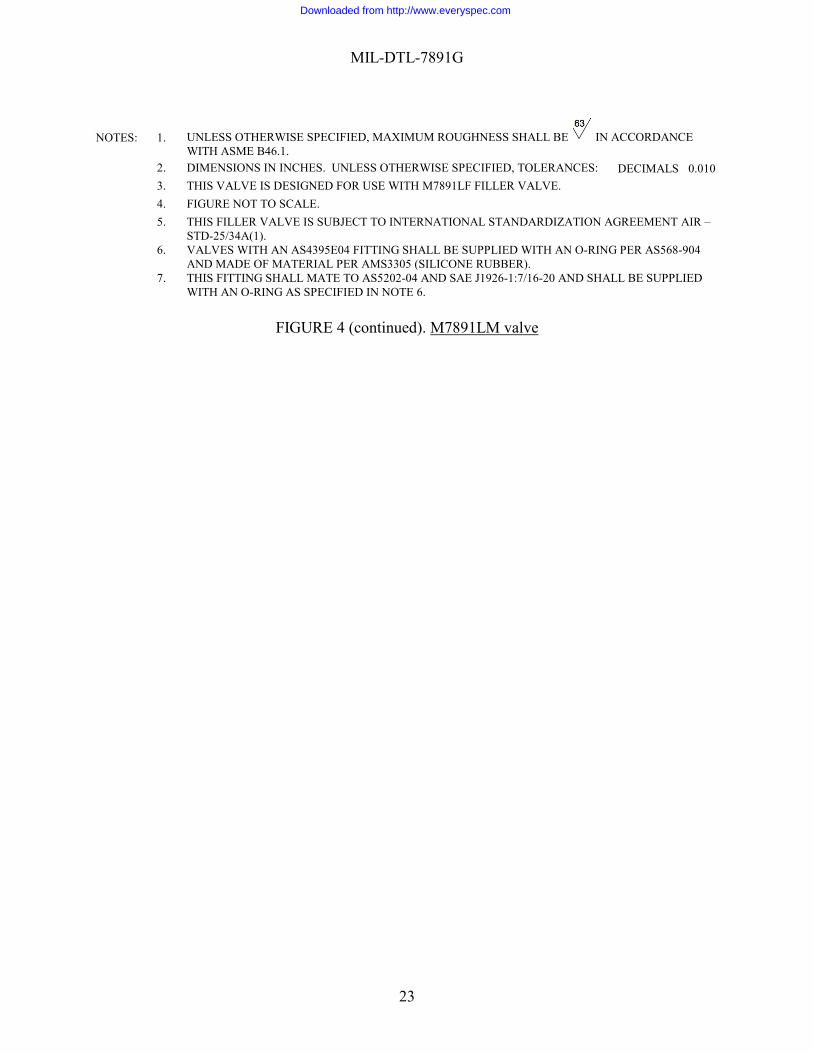
NOTES: 1. UNLESS OTHERWISE SPECIFIED, MAXIMUM ROUGHNESS SHALL BE IN ACCORDANCE WITH ASME B46.1.
2. DIMENSIONS IN INCHES. UNLESS OTHERWISE SPECIFIED, TOLERANCES: DECIMALS 0.010 3. THIS VALVE IS DESIGNED FOR USE WITH M7891LF FILLER VALVE. 4. FIGURE NOT TO SCALE. 5. THIS FILLER VALVE IS SUBJECT TO INTERNATIONAL STANDARDIZATION AGREEMENT AIR
STD-25/34A(1). 6. VALVES WITH AN AS4395E04 FITTING SHALL BE SUPPLIED WITH AN O-RING PER AS568-904
AND MADE OF MATERIAL PER AMS3305 (SILICONE RUBBER). 7. THIS FITTING SHALL MATE TO AS5202-04 AND SAE J1926-1:7/16-20 AND SHALL BE SUPPLIED
WITH AN O-RING AS SPECIFIED IN NOTE 6.
FIGURE 4 (continued). M7891LM valve
Downloaded from http://www.everyspec.com
MIL-DTL-7891G
24
PIN FITTING SIZE A B C ITEM M7891HM-1 MS 33677 0.125-27 1.000 0.391 0.437 VALVE, CAP & TETHER
M7891HM-2 AS 4395E03 (Note 6) 0.375-24 UNJF 3A 1.090 0.479 0.625 VALVE, CAP & TETHER
M7891HM-3 - - - - - CAP & TETHER
NOTES: 1. UNLESS OTHERWISE SPECIFIED, MAXIMUM ROUGHNESS SHALL BE IN ACCORDANCE WITH ASME B46.1.
3. THIS VALVE IS DESIGNED FOR USE WITH M7891HF FITTING. 4. FIGURE NOT TO SCALE.
5. MAXIMUM THREAD SURFACE ROUGHNESS SHALL BE IN ACCORDANCE WITH ASME B46.1.
6. VALVES WITH AN AS4395E04 FITTING SHALL BE SUPPLIED WITH AN O-RING PER AS568-904 AND MADE OF MATERIAL PER AMS3305 (SILICONE RUBBER).
FIGURE 5. M7891HM valve and cap
Downloaded from http://www.everyspec.com
MIL-DTL-7891G
25
PIN ITEM M7891HF-1 FITTING, CAP & TETHER M7891HF-2 CAP & TETHER
NOTES: 1. UNLESS OTHERWISE SPECIFIED, MAXIMUM ROUGHNESS SHALL BE IN ACCORDANCE WITH ASME B46.1.
2. THIS VALVE IS DESIGNED FOR USE WITH M7891HM VALVE. 3. FIGURE NOT TO SCALE.
4. HOUSING ROTATES AROUND TUBE, CONE, AND END FITTING ASSEMBLY.
5. MAXIMUM THREAD SURFACE ROUGHNESS SHALL BE IN ACCORDANCE WITH ASME B46.1. 6. AN 800-3 (BRASS) CONE MAY BE USED IN PLACE OF AN800N3 (MONEL) CONE.
FIGURE 6. M7891HF fitting
Downloaded from http://www.everyspec.com
MIL-DTL-7891G
26
Custodians: Preparing Activity: Air Force 71
Navy AS Army - AV
Air Force - 71
(Project 1660-2008-002)
Review Activities: Air Force 99 DLA -CC NOTE: The activities listed above were interested in this document as of the date of this document. Since organizations and responsibilities can change, you should verify the currency of the information above using the ASSIST Online database at http://assist.daps.mil/ .


![[NOT MEASUREMENT SENSITIVE] SUPERSEDING MIL-P-197Heveryspec.com/MIL-SPECS/MIL-SPECS-MIL-DTL/download.php?spec=… · [not measurement sensitive] mil-dtl-197j 9 july 2000 superseding](https://static.documents.pub/doc/80x56/5b80c51f7f8b9af7088e17c6/not-measurement-sensitive-superseding-mil-p-not-measurement-sensitive-mil-dtl-197j.jpg)


