Aircraft Type and Registration: De Havilland Canada DHC-8 Series 311, G-NVSB
No & Type of Engines: 2 Pratt & Whitney Canada PW123 turboprop engines
Year of Manufacture: �998
Date & Time (UTC): 9 August 2005 at 0830 hrs
Location: On departure from Manchester A�rport
Type of Flight: Publ�c Transport (Passenger)
Persons on Board: Crew - 4 Passengers - 33
Injuries: Crew - None Passengers - None
Nature of Damage: Damage to r�ght eng�ne and propeller assembly
Commander’s Licence: A�rl�ne Transport P�lot’s L�cence
Commander’s Age: 62 years
Commander’s Flying Experience: �5,735 hours (of wh�ch 3,634 were on type) Last 90 days - 205 hours Last 28 days - 8� hours
Information Source: AAIB F�eld Invest�gat�on
Synopsis
Shortly after takeoff from Manchester the No 2 (r�ght) eng�ne fa�led and subsequent attempts to feather the propeller were unsuccessful. The aircraft returned to Manchester where it made an uneventful landing. The No � propeller blade support bear�ng of the r�ght propeller assembly had fa�led catastroph�cally, result�ng in large imbalance loads through the engine. This led to the fracture of the Power Turb�ne (PT) shaft, and a consequent overspeed of the PTs, lead�ng to the loss of the PT blades and an exhaust baffle plate from the rear of the engine. The failure of the propeller to feather was due to a ball from the fa�led bear�ng becom�ng jammed between the propeller blade root and the propeller hub. The or�g�n of the bear�ng fa�lure was not determ�ned although metallurgic examination revealed that cracking
had been occurring for a period of time. Six days prior
to the �nc�dent, heavy v�brat�on was reported but, as
v�brat�on survey equ�pment was not ava�lable at the t�me,
the defect was deferred �n accordance w�th the a�rcraft
operator’s technical instruction. When vibration survey
equipment was fitted, it was set up incorrectly and a full
v�brat�on survey was not carr�ed out pr�or to the �nc�dent
flight. Two safety recommendations are made.
History of the flight
The aircraft was on a scheduled passenger flight
from Manchester to Aberdeen. Prior to the flight
the commander and co-p�lot had been �nformed by
the company operat�ons department that a propeller
vibration survey was required during the flight. The commander had flown the aircraft the previous day, dur�ng wh�ch he was due to take read�ngs us�ng a monitoring kit that had been fitted specifically for the measurement of reported propeller vibration. During this flight, the commander felt that the vibration levels peaked dur�ng propeller speeds of between 900 rpm and 1200 rpm and that this was worse than normal. However, the vibration monitoring equipment was not work�ng correctly so the commander was unable to take any meaningful readings.
The co-pilot was the pilot flying (PF) on the incident flight; the commander was the pilot not flying (PNF). After the eng�nes were started normal checks were carried out with no reported problems, except that dur�ng the de-�c�ng checks, a�rframe v�brat�on was felt with the propellers at 900 rpm. When the aircraft lined up on the runway, a check of the autofeather system was carried out, again with no problems. However, during the takeoff the commander felt the a�rframe v�brat�on aga�n and thought �t had worsened compared w�th the flight he had carried out the previous day. As the flaps were retracted the crew d�scussed the v�brat�on level and considered a possible return to Manchester.
In accordance w�th standard procedure, the autofeather system was deselected and eng�ne power was reduced, at wh�ch po�nt there was a ‘pop’ and a ‘bang’, heavy v�brat�on was felt and the aircraft yawed to the right. The PF noticed that the torque �nd�cator for eng�ne No 2 was show�ng 0% and therefore he called for the eng�ne shutdown dr�ll to be carried out. The PNF completed the shutdown drill but the propeller d�d not feather when the cond�t�on lever was selected to START & FEATHER. ALTERNATE FEATHER was selected, but the propeller would still not feather. The propeller speed indication remained at about 500 rpm for the remainder of the flight.
A MAYDAY call was made and ATC gave the crew a
priority visual circuit for an approach to runway 24R.
The flight crew briefed the cabin crew about the problem
and instructed them to prepare for an emergency landing.
At about four m�les from touchdown the land�ng gear
was selected down, but only the ma�n land�ng gears
�nd�cated as ‘down and locked’; the nose land�ng gear
indicated ‘unsafe’. The alternate landing gear release
was used, successfully, and the approach cont�nued
to an uneventful landing. The aircraft vacated the
runway and was met by the airfield Rescue and Fire
Fighting Service (RFFS), who reported that there were
signs of overheating on the left main gear wheels. A
precaut�onary evacuat�on of the passengers was carr�ed
out using the integral airstairs on the forward left door.
The co-p�lot had rema�ned as PF dur�ng the �nc�dent, as
the commander felt that there was not an appropr�ate
opportunity for him to have safely taken control.
On the day of the �nc�dent, a member of the publ�c had
been riding a horse in a field to the south of Manchester
a�rport, and had seen a “s�zzl�ng hot” object the s�ze and
shape of a d�nner plate fall from an a�rcraft and land
nearby. The time at which this object had fallen was
concurrent with the overflight of G-NVSB and it was
later confirmed that the object was a baffle from the rear
exhaust section of the aircraft’s No 2 engine.
Weather
The weather at the t�me was reported as be�ng good w�th
a w�nd of �50°/5 kt, v�s�b�l�ty 9 km and broken cloud at
8,800 ft.
Aircraft Description
General
The Dash 8-300 a�rcraft �s powered by two Pratt and
a four-bladed Hamilton Sundstrand constant speed propeller, wh�ch can be feathered and reversed. G-NVSB was fitted with Type 14SF-15 propeller blades.
Engine
The PW123 engine gas generator �s compr�sed of two spools. The first spool �s a s�ngle Low Pressure (LP) centr�fugal compressor wh�ch �s shaft driven by a single LP turbine. The second spool is a high pressure (HP) centrifugal compressor, also shaft driven, by a single HP turbine. Power is provided to the propeller, via a reduction gear box, by a two stage free PT located at the rear of the engine. This shaft rotates clockw�se and runs �nternally w�th�n the LP shaft, wh�ch �n turn rotates ant�clockw�se w�th�n the clockw�se rotating HP shaft. Each shaft is supported by various bearings throughout the engine.
The eng�ne conta�ns a wet sump o�l lubr�cat�on system, pressur�sed by a pump dr�ven by the accessory gear box (AGB). Scavenge pumps, also driven by the AGB, return used oil to the sump. An auxiliary oil tank is located within the reduction gearbox and this is kept full, be�ng replen�shed w�th pressur�sed o�l whenever the engine is running.
To the rear of the engine, aft of the PT stage, is an exhaust assembly, the centre of which contains a baffle plate.
Engine Control and Indication
Two eng�ne power levers control the eng�ne speed �n the forward power range, and propeller blade p�tch angle in idle and reverse ‘beta’ range. Two condition
levers, located to the r�ght of the eng�ne power levers, prov�de control over propeller speed between �,200 rpm (MAX) and 900 rpm (MIN), by alter�ng the propeller blade p�tch over a range of +26° to +86°. Moving the condition lever aft to START&FEATHER causes the propeller blade angle to be manually commanded �nto the feather setting. The full aft position is FUEL OFF, which cuts off fuel supply to the engine.
Eng�ne torque for each eng�ne �s �nd�cated as a percentage and is displayed to the flight crew on the centre instrument panel. The torque signal is taken from a sensor located on the front �nlet case of the eng�ne and th�s senses the passing of teeth on the PT torque shaft as it rotates. A s�m�lar set of teeth are mounted on an unloaded reference tube and �t �s the phase d�fference between the pass�ng of the teeth on the torque shaft and the reference tube wh�ch determines the torque output indication of the engine. The pass�ng frequency of the teeth on the torque shaft also determ�nes the PT speed (NPT).
The speed of each propeller is also indicated to the flight crew and �s generated by a speed sensor located w�th�n the reduction gear box.
The propeller assembly cons�sts of four propeller blades reta�ned w�th�n a hub, wh�ch conta�ns the blade p�tch change mechanism. Each blade is reta�ned and supported by bear�ngs wh�ch cons�st of a s�ngle p�ece outer race, a s�ngle or spl�t �nner race, and steel balls separated by a nylon cage. A nylon bear�ng race reta�ner r�ng holds the outer bear�ng race in position. Spring blade seals, kept �n place w�th a seal support r�ng and spacer, seal the blade to the hub and are reta�ned stat�cally by an aluminum retaining ring.
The propeller control un�t (PCU) uses h�gh pressure o�l suppl�ed from the eng�ne o�l system to control the propeller blades pitch angle. This is determined from propeller speed, eng�ne speed and cond�t�on lever position. The PCU controls the supply of oil to the p�tch change mechan�sm p�ston, wh�ch then dr�ves yokes connected to rollers on the bottom of each of the propeller blades. The fore and aft motion of the yokes �mparts a rotat�onal movement to each blade, thereby changing the pitch angle.
Propeller feathering
Propeller feathering on the DHC Dash-8-300 can be e�ther automat�c, when the system �s armed, or manually commanded by the flight crew. There is also an alternate feather system, to be used should e�ther the automat�c feather system not operate or there �s a loss of engine oil pressure.
Automat�c feather�ng �s only armed dur�ng takeoff and is disarmed by the crew once established in the climb. Should the eng�ne torque drop below 28% dur�ng takeoff or the �n�t�al cl�mb, the PCU �s commanded to move the propeller blades of the affected eng�ne �nto feather and the rema�n�ng eng�ne �s then commanded, v�a �ts eng�ne control unit (ECU), to increase power (up-trim).
The manual command to feather a propeller, wh�lst the eng�ne �s runn�ng, �s accompl�shed by select�on of the condition lever into START&FEATHER position but there is no associated ‘up-trim’ of the remaining engine.
An ‘alternate feather’ system �s prov�ded so that a propeller may be feathered, v�a the PCU, but us�ng the auxiliary oil supply and separate oil pump. This system �s des�gned so that �t can prov�de feather�ng o�l pressure to the PCU in the event of a loss of engine oil pressure. ‘Alternate feather’ �s actuated by a sw�tch on the centre console �n the cockp�t, and requ�res the eng�ne power lever to be in a position at, or greater than, flight idle and the condition lever to be below the MIN setting.
Figure 2
Cross sect�on of a typ�cal propeller blade to hub �nstallat�on
Data from the aircraft’s flight data recorder covering the incident flight is presented in Figures 3 and 4.
Aircraft examination
The a�rcraft was �nspected by the a�rcraft operator’s maintenance organisation. Externally, there was evidence of a significant oil loss from the No 2 engine
propeller hub w�th o�l sta�n�ng ev�dent on the outs�de of
the engine cowls. On their removal, and after further
�nspect�on of the propeller assembly, �t was revealed that
one of the propeller blade support bear�ngs had fa�led
catastrophically. The remains of the bearing inner race,
ball and ball race support cage had been reta�ned w�th�n
the propeller hub. All four propeller blades had remained
attached to the hub.
Figure 3
Salient FDR Parameters(Incident to G-NVSB on 9 August 2005)
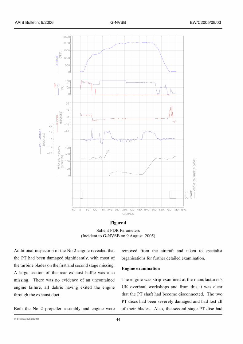
Add�t�onal �nspect�on of the No 2 eng�ne revealed that the PT had been damaged significantly, with most of the turbine blades on the first and second stage missing. A large section of the rear exhaust baffle was also missing. There was no evidence of an uncontained engine failure, all debris having exited the engine through the exhaust duct.
Both the No 2 propeller assembly and eng�ne were
removed from the a�rcraft and taken to spec�al�st
organisations for further detailed examination.
Engine examination
The engine was strip examined at the manufacturer’s UK overhaul workshops and from th�s �t was clear that the PT shaft had become disconnected. The two PT d�scs had been severely damaged and had lost all of their blades. Also, the second stage PT disc had
Figure 4
Salient FDR Parameters(Incident to G-NVSB on 9 August 2005)
come into contact with the exhaust duct and, in the
process, had ‘machined’ into the baffle plate, causing
it to depart from the rear of the engine. This disc
had then fr�ct�on welded �tself to the rema�ns of the
exhaust duct, Figure 5.
The PT shaft had fa�led just forward of the PT stages
and, on �ts removal, ev�dence of damage cons�stent w�th
a torsional failure became apparent, Figure 6. Associated
rubb�ng damage was present on the �nner sect�on of the
LP shaft. The HP and LP turbine discs were relatively
�ntact w�th some rubb�ng ev�dent on the t�ps of the blades;
add�t�onally, there were some l�ght marks ev�dent on the HP and LP centrifugal compressors where they had made contact with the engine caseing.
Propeller examination
The propeller assembly was strip examined at a specialist workshop. This revealed that the failed blade support bear�ng was that assoc�ated w�th propeller blade No 1. Blade Nos 2, 3 and 4 had been removed from the hub pr�or to sh�pp�ng and all appeared to be �n a sat�sfactory cond�t�on; the damage assoc�ated w�th blade No 1 precluded its immediate removal. Once
removed, �t was ev�dent that the �nner race, ball race and ball reta�ner of the blade support bear�ng had all been significantly damaged and were �n many p�eces, Figure 7. The outer race rema�ned �n one p�ece �n the hub, although it exhibited signs of
galling, brinelling and impact damage. The nylon bear�ng race reta�ner was also damaged and found �n two pieces.
Ev�dence was found that a ball had become trapped between the blade shank and the hub, w�th heavy w�tness marks cons�stent w�th the ball hav�ng moved w�th the rotat�on of the blade toward the feather p�tch pos�t�on, Figure 8. The relative positions of these marks indicated that the blade p�tch angle was 3�° when the damage occurred. It was evident that the ball had jammed the
propeller blade p�tch at th�s pos�t�on and, consequently, had prevented further movement of all the propeller blades �nto the feather (86° pitch) position. In addition, the drive roller at the base of the No 1 blade was bent.
No 2 engine propeller assembly history
In the or�g�nal bu�ld, the blade retent�on bear�ngs used in this hub assembly used a single piece inner race. A split inner race could have been retrofitted whenever the propeller assembly was overhauled or part�ally disassembled for any reason, if judged necessary.
Figure 7
Damaged components of the No � propeller blasé support bear�ng
Figure 8
The propeller p�tch change mechan�sm and the PCU were checked and found to be sat�sfactory
Smear from ball bearing becoming jammed between hub and shank
The c�rcumferent�al scor�ng on the �ns�de of the LP shaft and the tors�onal overload�ng of the PT was as a result of contact with each other. The fracture of the PT shaft occurred at its splined aft end and the fracture exhibited evidence of fatigue cracking, with the final failure due to torsional loading. Neither of the two shafts possessed any pre-existing defects and their material was confirmed as being to design specification.
No 1 propeller blade support bearing
Metallurgic examination of the remains of the No 1 blade retent�on bear�ng revealed that �ts �nner race had fa�led mainly due to overload. Due to the severe nature of the damage, �t was not poss�ble to determ�ne the root cause of the fa�lure; however, corros�on of the fracture surfaces �nd�cated that cracks had developed over a relat�vely long period of time prior to its final failure and break up. Some of these cracks had originated from brinelling of the �nner race surface, wh�ch was also ev�dent on the outer race, and was cons�stent w�th the balls str�k�ng, or hammering, the bearing race surface. The irregular
pattern of the br�nell�ng suggested that th�s damage had also been progressive over a period of time. The bearing material conformed to the original design specification.
Bearing life
The propeller blade support bear�ngs do not have a specified life and are considered to be ‘on condition’. Due to the�r locat�on, they cannot be �nspected �n-s�tu and can only be �nspected �f the propeller blade �s removed, wh�ch normally w�ll only occur dur�ng a workshop visit. The time this is likely to occur is during a major overhaul of the propeller assembly, follow�ng damage to a propeller blade or follow�ng a report of an overtorque on the propeller assembly.
Aircraft vibration history
The techn�cal log for the a�rcraft revealed that an entry had been made on 3 August 2005 for propeller v�brat�on and it stated:
‘Prop vibration felt throughout RPM 900 - 1200 particularly bad between 980 - 1080 RPM’
The action taken was:
‘Noted with thanks. Due nil test equipment @ MAN ADD1 P147 raised IAW TI D83-61-02’
Techn�cal Instruct�on (TI) D83-6�-02, �ssued �n December 2003 by the operator, allowed, at the d�scret�on of the eng�neer, the deferral of a reported propeller vibration defect for a maximum of 50 flying hours. There were no other entries relating to the propeller v�brat�on unt�l 6 August 2005 when the
Footnote
� ADD – Acceptable Deferred Defect, wh�ch �s a numbered reference to a reported defect that has been deferred for later rectification.
Bear�ng No �
Overhauled at �0,583 hours on 10.10.01 and fitted to G-NVSB with TSO of 1083.49 hours on 25.08.02. Failed at 16,714 hours. Single piece inner race.
propeller balance test equipment was fitted, with a reference to ADD P147. During the subsequent flight, �n wh�ch the propeller balance survey was carr�ed out, the results conta�ned a fault code on the equ�pment, indicating that it had been incorrectly set up. This problem was addressed and a request was made for an additional survey to be carried out on the next sector. However, despite the equipment being fitted, no record was found of any in-flight vibration survey being carried out. Overnight 8/9 August 2005, another request was made, us�ng the techn�cal log, for a v�brat�on survey to be carried out on the next flight. The incident occurred on the first flight following this request.
The commander of the incident flight had flown the a�rcraft on the prev�ous day and had attempted to carry out a v�brat�on survey, but found the v�brat�on mon�tor�ng equ�pment to be faulty; no record of th�s was found �n the technical log.
Vibration monitoring
G-NVSB was not equipped with any form of propeller v�brat�on �nd�cat�on or other mon�tor�ng equ�pment for use in normal operation. The aircraft maintenance manual (MM) prov�des deta�ls on how to conduct propeller vibration measurements on these aircraft. This requires the use of test equipment to be fitted to the a�rcraft to enable the v�brat�on levels from each propeller to be recorded. The MM specifies the use of the Chadwick-Helmuth CH-8500 series vibration analyzer. However, at the time of the incident, the operator of G-NVSB was using alternative equipment, and �ts assoc�ated operat�ng manual, �n l�eu of that g�ven in the aircraft MM.
The maintenance manual states:
‘Note: Propeller dynamic balancing cannot be successfully performed on the ground. Operate aircraft in stable air (nominally 10,000 ft altitude) with no icing conditions. Aircraft should be trimmed for straight and level flight…’
It also states:
‘Because of the propeller vibrations produced by both propellers are at the same frequency (same RPMs), one propeller may influence the reading obtained for the other propeller. Therefore an extra data collection flight (or two) may be necessary before an acceptable balance (0.15 IPS or less) is achieved’
The only l�m�t g�ven w�th regard to v�brat�on levels �s
that specified above, ie 0.15 inches per second (IPS).
The a�rcraft manufacturer does not prov�de v�brat�on
l�m�ts wh�ch would tr�gger �nvest�gat�on of the propeller
or engine prior to a further survey flight.
At the t�me of the �nc�dent, the operator conducted
propeller v�brat�on surveys on normal scheduled
passenger flights, with the flight crew expected to
operate the monitoring equipment to take the readings.
The Dash 8 Q400 series of aircraft is fitted with a
propeller v�brat�on and balance mon�tor�ng system wh�ch
is coupled to the active noise cancelling system.
There are permanent on-board propeller v�brat�on and
balance monitoring systems that can be fitted to the
DHC 8-311. These are not provided by the aircraft
manufacturer, but by other component manufacturers
and are certificated to be fitted to the aircraft by the issue
of an approved supplemental type certificate (STC).
Accord�ng to the propeller manufacturer, over at least
the last twenty years, they know of five previous
occurrences �n wh�ch the propeller blade support bear�ng
has failed. In each of these events the initial symptom
was v�brat�on, w�th a result�ng eng�ne shutdown or a
reduction in engine power. All propeller blades were
retained in the hub in these events.
Analysis
The fa�lure of the No 2 eng�ne, and subsequent fa�lure
of the propeller to feather at a critical stage of flight,
exposed the flight crew to a situation which they would
not normally experience and one for which they were
not trained. However, the prompt actions taken by
the flight crew enabled a safe return and landing. It
was fortunate that desp�te the propeller not be�ng fully
feathered, sufficient rudder authority was available to
maintain directional control.
The cause of the �nc�dent was due to a catastroph�c
fa�lure of the No � propeller blade support bear�ng,
forming part of the No 2 engine propeller assembly.
The bear�ng appears to have broken up just after takeoff
just as engine power was being reduced. The ‘pop’ and
‘bang’ reported by the flight crew was likely to have
been the propeller blade support bear�ng fa�lure and the
subsequent rapid engine failure; all damage identified
�n the eng�ne was cons�stent w�th be�ng a d�rect result
of the failure of this bearing.
Follow�ng the fa�lure, large out of balance loads would
have been generated wh�ch affected not only the
propeller assembly but also the eng�ne’s power dr�ve
system, in particular, the PT shaft. The out of balance
loads caused the PT shaft to ‘wh�p’ and come �n contact
w�th the �nner surface of the contra-rotat�ng LP shaft,
result�ng �n a large tors�onal load �n the PT shaft and �ts eventual fracture. This disconnected the two PT stages, wh�ch very qu�ckly oversped, mov�ng aft �n the process, and shedding their blades from the engine exhaust. The 2nd stage PT d�sc had also come �nto contact w�th, and welded itself to, the exhaust assembly, which removed enough material to allow the rear exhaust baffle plate to become detached.
The PT shaft fa�lure removed all torque to the propeller and produced the 0% torque indication in the cockpit. The subsequent shutdown of the eng�ne was successful, however, the feather�ng of the propeller could not be completed. A ball from the failed bearing prevented complete movement of the propeller blade �n p�tch, when �t had become jammed between the blade shank and the hub. This effectively locked the propeller pitch angle at 3�º, caus�ng the propeller assembly to w�ndm�ll at about 500 rpm.
The cause of the bearing failure was not determined. The bear�ng had completed �6,7�4 hours �n serv�ce so, �n�t�ally, �t was thought that �ts age was a contr�but�ng factor. However, the blade No 2 bearing of the same assembly had completed 24,737 hours and showed no signs of an impending failure. The propeller manufacturer has knowledge of only five previous �nstances of bear�ng fa�lures �n serv�ce and, as such, th�s failure is considered quite a rare occurrence. Therefore, �t �s unl�kely that the fa�lure was ‘t�me-�n-serv�ce’ related. It was also unlikely that the failure was due to an �nstallat�on problem as the propeller had been fitted within the hub and had apparently been operating sat�sfactor�ly for over 5,000 hours, of the four and had not been disturbed during that time. The brinelling damage to the bear�ng races �nd�cates that the balls had been free to move w�th�n the races, as the marks were generated by the balls striking the races. It is possible
that there had e�ther been a fa�lure of the ball cage,
or the reta�n�ng cl�p for the ball race had fractured or
become detached, as �t was not located �n the rema�ns
recovered from the propeller hub. It was also possible,
�n the manufacturer’s v�ew, that the lubr�cat�ng o�l
w�th�n the propeller hub could have been contam�nated
w�th hard part�cles, wh�ch may have �nduced fat�gue
crack�ng and prec�p�tated the �n�t�al fa�lure of the �nner
bearing race.
As the fa�lure was l�m�ted to only one bear�ng w�th�n
the propeller assembly, �t �s unl�kely that an overtorque
event had prec�p�tated the fa�lure, as th�s would
equally affect all the bearings. Similarly, there was
no external damage to the propeller blade or a report
of any prev�ous damage that could have �nduced loads
required to initiate the bearing failure.
Although, it was not possible to determine the exact
cause of the bear�ng fa�lure, �t appears there were
warn�ng s�gns (v�brat�on) of the �mpend�ng fa�lure that,
if heeded in time, might have prevented the failure.
Metallurgic examination has shown that cracks had
developed, and been in existence for some time, prior
to the break up of the �nner race and that some of these
cracks originated from brinelling marks. The reports
�n the techn�cal log �nd�cated that v�brat�on had been
evident during a flight on 3 August 2005, some six days
prior to the incident. It is considered likely that this
v�brat�on was due to the early stages of propeller blade
support bearing failure.
At the t�me of th�s �nc�dent, the operator allowed
propeller v�brat�on defects to be deferred, desp�te
hav�ng no method to quant�fy the sever�ty of the
vibration or its origin. This operator’s aircraft type is
not equ�pped w�th an on-board v�brat�on mon�tor�ng or
�nd�cat�on system, so the determ�nat�on of sever�ty of
any v�brat�on �s purely a subject�ve assessment by the crew. The only way to measure vibration is to fit test equipment and conduct a flight on which the vibration level can be ascertained. Indeed, it would appear that the �ntent�on of a deferral �s to allow the a�rcraft to cont�nue �n serv�ce unt�l v�brat�on test equ�pment becomes available.
In the case of G-NVSB, the raising of a deferred defect �n the techn�cal log, was due to the unava�lab�l�ty of test equipment. It was not until 6 August 2005, that the test equipment was finally fitted. Despite this, the subsequent measurements taken were unusable due to a fault in its set up. This included an attempt by the commander of the incident flight, the day before, dur�ng wh�ch he also found the survey equ�pment faulty. Finally, a request was made, via the technical log, for a survey flight. Unfortunately, the incident flight was the first flight following this request.
Had a full vibration survey been successfully carried out, �t �s not known whether the fa�led bear�ng would have been immediately identified. The maintenance manual procedure �s to, �n�t�ally rebalance the propeller, based on the survey �nformat�on, and to cont�nue to do so until the vibration drops to the specified acceptable limit of 0.15 IPS. There is no information in the ma�ntenance manual to gu�de the operator to look deeper �nto the propeller assembly for other poss�ble causes, or damage; �ndeed, there �s no upper l�m�t to the v�brat�on level at wh�ch �t �s deemed unacceptable to continue flight without a thorough examination of the assembly.
Therefore the following safety recommendation is made:
It �s recommended that Transport Canada requ�re the a�rcraft manufacturer, Bombard�er Aerospace, to amend the maintenance manual for the DHC Dash 8-300 a�rcraft w�th regard to propeller v�brat�on measurements and to prov�de �nstruct�ons when to �nvest�gate the propeller and/or eng�ne assembly for poss�ble �nternal damage, based on measured v�brat�on levels, and to provide specific vibration level limits at which detailed inspections are required.
In a response to th�s safety recommendat�on, Transport Canada stated the following:
‘Transport Canada agrees with the intent of this recommendation. If appropriate Instructions for Continued Airworthiness (ICA) or other operational limitations for procedures regarding significant or unusual vibration events were in place at the time of the initial event noted in the “Aircraft Vibration History” [page 47 �n th�s Bullet�n], the bearing failure and subsequent events may have been prevented.’
In response to th�s safety recommendat�on, the a�rcraft manufacturer have provided the following information:
‘We were recently informed by Hamilton Sundstrand that they are planning to incorporate a “Vibration Note” into their maintenance documentation. Bombardier Aerospace will review this note and make a similar change to our Aircraft Maintenance Manual (AMM). At present, there are two independent Supplemental Type Certificates (STCs) available to permantly install propeller vibration monitoring equipment in the Q100, 200 and 300 DHC-8 aircraft………
…..Reporting of abnormal vibrations in flight is very subjective. Flight crew experience and familiarity with the subject aircraft is an important criteria with identifying abnormal aircraft vibration. In our opinion, the investigation of a flight crew noted vibration scenario would highlight potential areas of concern including engine and propeller issues. The response to the reported inflight vibration will confirm either a propeller imbalance or direct maintenance to persue investigation elsewhere.’
As �t �s not poss�ble to conduct a mean�ngful v�brat�on survey w�th the a�rcraft on the ground, the a�rcraft has to be flown, but with the risk that an incipient defect may become critical during the flight. It has been a common pract�ce to conduct these v�brat�on surveys on revenue passenger carrying flights, using line pilots, who may not be fully conversant w�th the mon�tor�ng equipment. This practice comes with the attendant r�sk of a fa�lure occurr�ng, wh�ch may necess�tate an emergency, as was the case with G-NVSB. It also leads to the poss�b�l�ty of �ncorrect use of the mon�tor�ng equ�pment and �ncorrect read�ngs be�ng taken, requiring further survey flights. If a vibration problem has already been identified on an aircraft, it would seem more prudent to conduct the v�brat�on survey using crew members that are experienced in using the test equipment and to fly the aircraft without passengers.
Therefore the following safety recommendation is made:
Safety Recommendation 2006-068
It �s recommended that Transport Canada requ�re the a�rcraft manufacturer, Bombard�er Aerospace, to amend the DHC Dash 8-300 maintenance manual with regard
to propeller vibration monitoring flights, to ensure that v�brat�on surveys are only conducted on non-revenue flights by appropriately trained crews.
As a d�rect result of th�s �nc�dent, the operator now carr�es out all a�rborne checks of propeller v�brat�on levels us�ng AMM approved equ�pment wh�ch �s deployed only during dedicated non-revenue ‘function flights’.
In add�t�on, the a�rcraft manufacturer has stated that they support:
‘the fact that flight crews must be adequately trained and proficient in the use of the propeller balancing [v�brat�on measur�ng] equipment, prior to undertaking this task.’
However, they:
‘believe that mandating of this recommendation [2006-068] must remain at regulatory authority level. If it is decided that this task can be performed on a revenue flight, it is mandatory that it be performed during low workload periods (such as cruise flight), by an appropriately trained proficient crew.’